1
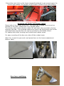
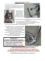
CAE Shifting Technology 45141 ESSEN Christian Au Leimkugelstrasse 3 45141 Essen Phone +49 201 8777 802 e-mail: [email protected] www.cae-racing.de Installation Manual CAE ULTRA-SHIFTER CAE ULTRA-SHIFTER VW Golf I VW 02M/J Getriebe Typ MQ200/250/350 Art No: 10004HD-02M/J The shifter is intended for Racing Cars without interior equipment. If center console is mounted, it must be dismounted or modified to achieve an acceptable space for the cables. The new unit should be mounted directly on to the floorboard, so part of the carpet must be removed. Before the assembly of the Balljoints lubricate the seat with good grease. After completing the shifter, secure the Ballstud with a cotter pin. All screws and nuts on the shifter must have Lock-Tite or anything that keeps the screws or nuts from coming loose. Never bend the controller cables! To avoid rust film, clean the steel parts with oil ever so often. To clean the Alu-parts use ethyl alcohol Remove Remove the original parts of the shifter completely Bodywork Extend the stock Hole in the frame triangle/frontboard to get enough space for the for both cables. The position of this holes is shown in the next picture Before drilling you must check if the cables have enough space. If not, change position of holes as far as necessary. Mounting the shifter and shifter cables Mount both of the cables at the unit. The cable has to stand out as much as possible of the case, inside there is no thread visible. The shorter cable is the selection cable (W) and has to be mounted in driving direction left side.. The mounted cables now have to be fed through the former extended body hole and the unit can be mounted on the Middle tunnel. For sealing the shifter housing use the delivered rubber stripe. For easy mounting of the big nuts, take off the rubber boots. After this, mount the pan-ends and press them on the levers (adjustment follows later) Gear lever modifying: 2 If not our leverkit 10017KIT was ordered, the existing gear lever have to be reworked. NOTE: The plastic lever can’t be reworked Cut of the vibration eleminator-weight from gear lever shown on the next picture: Drill out the stock bolts (8mm) on both levers and mount the delivered Ball pins: Remount both levers back to the gearbox also the cable bracket. Mount the cables and levers to the gearbox as shown: 3 Adjusting 5& 6 Speed Gearbox Pull the connector rod off >> Now Select the 3rd gear manually. The 3rd gear is the middle position. To select it, pull the gearshift-lever forwards or backwards. Now adjust the wanted middle position of the gearshift and adjust the lower spring stop under the unit with allen wrench. In middle position the gearshift should be slightly turned to the right. Push the connector rod back to the ball pin. For this adjust the connector rod (right/left thread) for pushing on without moving the lever. Now the 3rd /4th gear have to be shifted clearly. Now Select level 1 / 2 with gearshift and adjust the shown stop screw until the gears 1 and 2 can be selected well. Now select gear 5 with the gearshift and adjust the shown turn stop screw until the 5th gear can be selected clearly. Pull the reverse gear lock out mechanism and enter reverse gear. Adjust the shown stop screw until the rear gear can be selected clearly. Attention !! Protect shiftcables against thermic overheat by delivered blue heat resistant tube. Protected cables must not contact the exhaust system. After installation, check all the essential functions of the Shifter while driving and readjust if necessary. Wrong adjustment will destroy your gearbox If you experience any problems or questions, please contact us absolutely, we need YOUR feedback to improve our products CAE Shifting Technology wishes you a good trip 4