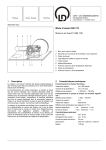
1
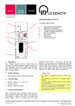
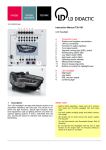
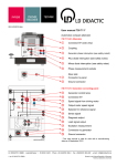
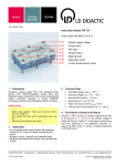
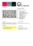
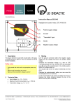
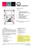
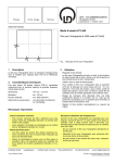
10/14-W2010-Wei Instruction Manual 739 660 EOBD/OBD2 Simulator 1 2 3 4 5 6 7 8 9 10 11 12 13 14 15 1 Description This "EOBD/OBD2 simulator" simulates data pertaining to exhaust gas. The potentiometer lets you alter the sensor data for the vehicle's speed, engine RPM, engine temperature, oxygen sensor voltage and mass air flow while driving. In addition, pressing a button can simulate the appearance of faults in the vehicle. This leads to the corresponding fault entries in the control unit and the illumination of the MIL (malfunction indicator lamp), which the tester can also cancel. So it is easy to generate fully reproducible faults without extensive manipulation of the vehicle. Safety notes - Before initial operation, make sure all ground connections are plugged in! - Use only safety bridging plugs and safety connection leads! - Be careful not to short-circuit the battery terminals. Fire hazard! 2 Battery + connection Oxygen sensor voltage adjuster Air mass adjuster Lambda voltage change-over switch, constant/periodic alternation between 0.1 and 1 V Engine temperature adjuster Fault reset Engine speed adjuster CAN bus High measurement socket CAN bus Low measurement socket Malfunction indicator lamp Fault setting Vehicle speed adjuster Diagnostic plug Connection for 12 V=/1 A AC adapter Battery - connection Scope of Supply EOBD/OBD2 simulator Additionally required Power supply (e.g. LD 738 026) Scan tool (e.g. 737 9803) 3 Technical Data Compatible with ISO 15765-4 Number of control units: 3 OBD modes: 1, 2, 3, 4, 7 and 9 Adjustable actual values: 5 (air mass, engine temperature, vehicle speed, engine RPM, oxygen sensor voltage) CAN interface: 11 bits, 500 kbit/s CAN bus Supply voltage: UB = +12 – +15 V= Instruction Manual 4 Page 2/2 Setup and Function Setup Link the diagnostic adapter to the 16-pin diagnostic plug (13). Function The system requires 12 VDC for operation. Connect an appropriate power adapter to sockets 1 and 15, or 14. 5 Operation Switch the power supply on. Note: The red and yellow LED's briefly light up in succession as a functional test. You can now read the relevant data. After pressing the button (11), you generate faults, and the MIL lights up. 6 OBD2/EOBD Diagnosis The diagnostic software can read the faults. Start the diagnostic software. When working with VCDS, after the program starts up, press the "OBD-II/EOBD" button: LD DIDACTIC GMBH Leyboldstrasse 1 D-50354 Huerth / Germany Phone +49 (0)2233 604-0 Fax +49 (0)2233 604-222 e-mail: [email protected] by LD Didactic GmbH Printed in the Federal Republic of Germany Technical alterations reserved