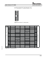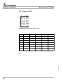
1
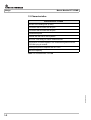
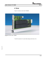
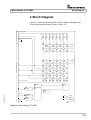
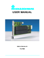
USER MANUAL
Matrix Module B
TS-PMB
User Manual
for ROHDE & SCHWARZ Matrix Module B TS-PMB
3rd Issue / 11.05 / GB 1153.5233.12
All rights, also translation into foreign languages, are reserved. No part of this manual is permitted
to be reproduced in any form (print, photocopy or any other method), also not for the preparation
of lectures, or processed, reproduced or made available using electronic systems without written
permission from ROHDE & SCHWARZ.
© The passing on to third parties and the reproduction of this documentation, utilisation and communication of its contents is not permitted unless specifically approved. Infringements will incur
claims for damages. All rights reserved in the case of the award of a patent or registration of a
design.
We draw to your attention that the names of software and hardware used in the Service Manual,
and the brand names of the respective companies are, in general, the subject of protection as
trademarks, or under proprietary rights, or patent law.
ROHDE & SCHWARZ GmbH & Co. KG
Corporate Headquarters
Mühldorfstr. 15
D-81671 München
Telephone:
Fax:
...49 (0)89/4129-13774
...49 (0)89/4129-13777
Printed in the Federal Republic of Germany. Errors excepted, subject to technical change without notice.
Safety Instructions
Attention!
Electrostatic
sensitive devices require
special care
Support Center
Telephone Europe:
+49 180 512 42 42
Telephone worldwide: +49 89 4129 13774
Fax:
+49 89 4129 13777
e-mail: [email protected]
If you have any technical queries about this Rohde &
Schwarz equipment, our Hotline at the Support Center of
Rohde & Schwarz Sales-GmbH will be glad to help.
Our team will discuss your queries and look for solutions to
your problems.
The Hotline is open Mondays to Fridays from 08.00 to 17.00
hrs.
For queries outside office hours, you can leave a message
or send a note via fax or email. We will then get back to you
as soon as possible.
Matrix Module B TS-PMB
Contents
Contents
1
1-1
1.1
General
1-1
1.2
Characteristics
1-2
2
View
2-1
3
Block Diagram
3-1
4
Layout
4-1
4.1
Mechanical Layout
4-1
4.2
Display Elements
4-2
Function Description
5-1
5.1
Signal Concept
5-1
5.2
Scalability
5-1
5.3
Noise Immunity
5-2
5.4
Relay Matrix
5-2
5.5
Interfaces
5-2
5.6
Power supply
5-3
5
6
7
3rd Issue 11.05
Usage
8
Commissioning
6-1
6.1
Installing the Plug-In Module
6-1
6.2
Initializing the Plug-In Module
6-1
6.3
Operation in the CompactTSVP TS-PCA3
6-2
Software
7-1
7.1
Driver Software
7-1
7.2
Softpanel
7-2
7.3
TS-PMB Program Example
7-3
Self-Test
8-1
8.1
LED Test:
8-1
8.2
Power-On Test
8-1
8.3
TSVP Self-Test
8-1
3
Contents
9
Matrix Module B TS-PMB
Interface description
9-1
9.1
Connector X10
9-1
9.2
Connector X20
9-3
9.3
Connector X1 (only Version 3.x)
9-5
9.4
Connector X30
9-6
10-1
3rd Issue 11.05
10 Specifications
4
Matrix Module B TS-PMB
Figures
Figures
View of the TS-PMB ...........................................................................2-1
Figure 3-1
Block Diagram TS-PMB.....................................................................3-1
Figure 3-2
Functional Block Diagram TS-PMB..................................................3-2
Figure 4-1
Layout of Connectors and LED's .....................................................4-1
Figure 7-1
Softpanel TS-PMB (example)............................................................7-2
Figure 9-1
Connector X10 (mating side) ............................................................9-1
Figure 9-2
Connector X20 (mating side) ............................................................9-3
Figure 9-3
Connector X1 (mating side) ..............................................................9-5
Figure 9-4
Connector X30 (mating side) ............................................................9-6
3rd Issue 11.05
Figure 2-1
5
Matrix Module B TS-PMB
3rd Issue 11.05
Figures
6
Matrix Module B TS-PMB
Tables
Tables
Characteristics TS-PMB ....................................................................1-2
Table 4-1
Connectors on the TS-PMB ..............................................................4-1
Table 4-2
Display Elements on the TS-PMB ....................................................4-2
Table 7-1
Driver Installation TS-PMB................................................................7-1
Table 8-1
Statements about the LED Test........................................................8-1
Table 9-1
X10 Pinning Schedule .......................................................................9-2
Table 9-2
X20 Pinning Schedule (Version 2.X) ................................................9-3
Table 9-3
X20 Pinning Schedule (Version 3.X) ................................................9-4
Table 9-4
X1 Pinning Schedule .........................................................................9-5
Table 9-5
X30 Pinning Schedule .......................................................................9-6
3rd Issue 11.05
Table 1-1
7
Matrix Module B TS-PMB
3rd Issue 11.05
Tables
8
Matrix Module B TS-PMB
Usage
1 Usage
1.1 General
The ROHDE & SCHWARZ Matrix Module B TS-PMB allows the universal interconnection of test points and measuring instruments. This can
be done locally or using the analog bus. The TS-PMB can be used in
the CompactTSVP and the PowerTSVP (TSVP = Test System Versatile Platform). Typical product test applications are in the fields of communications, automotive electronics and general industrial electronics,
especially for analog In-Circuit Testing with a large number of channels.
The TS-PMB is plugged into the front part of the TSVP chassis.
The front connector ends flush with the front panel of the TSVP chassis and is used for contacting the UUTs. An adapter frame can also be
used if necessary.
3rd Issue 11.05
At the rear, the TS-PMB is connected with connector X20 to the cPCI
backplane when used in the CompactTSVP or to the control backplane
when used in the PowerTSVP. Connector X30 is used to connect the
TS-PMB to the analog bus backplane. This connector can be used to
make connections with other plug-in modules (e.g. measuring modules) or external instruments.
1-1
Usage
Matrix Module B TS-PMB
1.2 Characteristics
Characteristics TS-PMB
Access to the analog bus (8-wire)
Full matrix with 4 buses with 90 pins
Full matrix with 8 buses with 45 pins
3 Instrument ports
Parallel test with two 4-wire systems
In-Circuit Test wiring for 6-wire measurements
Connection of control signals in the Powertest together with the
TS-PSM1 plug-in module.
Switchgear panel in adapters with no TSVP
Self-test capability
3rd Issue 11.05
Table 1-1 Characteristics TS-PMB
1-2
Matrix Module B TS-PMB
View
2 View
Figure 2-1 shows a view of the TS-PMB .
Figure 2-1 View of the TS-PMB
3rd Issue 11.05
The cPCI connector X1 is also fitted starting with Version V3.x.
2-1
Matrix Module B TS-PMB
3rd Issue 11.05
View
2-2
Matrix Module B TS-PMB
Block Diagram
3 Block Diagram
ABA2
ABB1
ABB2
ABC1
ABC2
ABD1
ABD2
LABA2
LABB1
LABB2
LABC1
LABC2
LABD1
LABD2
GND
ABA1
Analog Bus (AB)
LABA1
Analog Bus Connector X30
Figure 3-1 shows the block diagram of the TS-PMB. A simplified view
of the functional blocks can be seen in Figure 3-2 .
P1
P2
P3
P89
Extension Connector X20
P90
IL1
Front Connector X10
P4
IL2
IL3
Local Analog Bus (LAB)
Power Up
Test
SPI
Interface
LED
Control
uP,
Flash
Relay
Control
3rd Issue 11.05
GA0..GA5
Geographic
Addressing
CAN
Interface
GND
GND
GNDNO
GND
CHA-GND
Figure 3-1 Block Diagram TS-PMB
3-1
Block Diagram
Matrix Module B TS-PMB
3rd Issue 11.05
Figure 3-2 Functional Block Diagram TS-PMB
3-2
Matrix Module B TS-PMB
Layout
4 Layout
4.1 Mechanical Layout
The TS-PMB is designed as a long plug-in board for front mounting
in the TSVP chassis. The mounting depth is 300 mm, and the front panel is 4U in height.
Connector X20 is used to make the connections with the cPCI backplane/control backplane of the TSVP. Connector X30 connects the TSPMB with the analog bus backplane in the TSVP chassis. UUTs and
peripherals are connected using front connector X10.
Figure 4-1 Layout of Connectors and LED's
3rd Issue 11.05
Symbol
Use
X1
cPCI Connector (only Version V3.x)
X10
Front Connector
X20
Extension Connector
X30
Analog Bus Connector
Table 4-1 Connectors on the TS-PMB
4-1
Layout
Matrix Module B TS-PMB
4.2 Display Elements
(see Figure 4-1 )
The front panel of the TS-PMB contains three LEDs with the following
functions:
LED
Description
ERR
(red)
Error:
Lights up when a fault is detected on the TS-PMB in the
power-on test after the supply voltage is switched on.
COM
(yellow)
Communication:
Lights up briefly when the TS-PMB is accessed via the
interface.
Power
(green)
Power:
Lights up when all supply voltages are present.
Table 4-2 Display Elements on the TS-PMB
LED Test:
3rd Issue 11.05
When voltage is powered up all three LED's light up for around 1 second. This ensures that the 5 V supply is present and that the LED's and
power-on test are functioning.
4-2
Matrix Module B TS-PMB
Function Description
5 Function Description
5.1 Signal Concept
The TS-PMB allows the optional connection of measuring instruments
to pins on test products. Connections can be made locally within the
module or with other modules using the R&S analog bus. This means
that no constraints need to be allowed for when wiring test product
adapters because the measurement paths are created by software.
The ability to connect measuring instruments to the back of the TSVP
avoids cross-connections at the adapter interface. The unit's extreme
compactness makes it possible to accommodate measuring systems
with a number of PXI instruments and a switch panel with a large
number of pins in a single device (one-box solution), making is particularly suitable for in-circuit testing.
The ground can be connected to the front connector via the ground relay (GND - GNDNO).
5.2 Scalability
The TS-PMB has two switching matrices (4 x 45). These can also be
configured as 8 buses x 45 pins with external connection or 4 buses x
90 pins, e.g. using plug-in module TS-PSAM via the analog bus (see
Figure 3-2).
Three additional instrument inputs (IL1 ... IL3) can be used to connect
measuring instruments at the rear. Up to12 modules can be used in the
CompactTSVP.
3rd Issue 11.05
The switch panel can be divided into two 4-wire part buses for the parallel test. The number of pins can be increased to 16 modules with the
PowerTSVP.
5-1
Function Description
Matrix Module B TS-PMB
5.3 Noise Immunity
The signal concept with the analog bus remote from the Compact PCI
bus and the triggering via the CAN bus guarantee good signal quality.
Despite the unit's compact size, DC and AC voltages up 125 V (rms)
can be connected and passed to other modules.
5.4 Relay Matrix
The matrix is designed as a part matrix, i.e. each even I/O channel (e.g.
P2) can be switched to an even part bus (e.g. LABA2) and each odd
I/O channel (e.g. P1) can be switched to an off part bus (e.g. LABA1)
(see Section 3, Block Diagram). This does not apply to channels IL1 ...
IL3, which can be switched to all lines of the local analog bus.
Coupling relays separate the local analog bus lines (LAB) on the TSPMB from the bus lines on the analog bus backplane. The firmware automatically switches these relays selectively when at least one I/O
channel is switched to the corresponding local analog bus. When an
I/O channel is no longer switched to a bus, the corresponding coupling
relay is automatically opened. This function can be turned on or off at
any time. The coupling relays can also be switched manually.
5.5 Interfaces
(see Figure 3-2)
3rd Issue 11.05
The SPI interface (Serial Peripheral Interface) is used for communication with rear I/O modules. The TS-PMB is controlled via CAN interface
(Controller Area Network).
5-2
Matrix Module B TS-PMB
Function Description
5.6 Power supply
The TS-PMB is operated with a voltage of 5 V. The power supply is provided through connector X20 for Versions V1.x and V2.x. In Version
V3.x the power supply is provided via connector X20 or connector X1.
All versions of the TS-PMB can be operated in the CompactTSVP
TS-PCA3 and in the PowerTSVP TS-PWA3.
3rd Issue 11.05
Since the CompactTSVP TS-PCA3 no longer makes a 5-V power supply available on connector X20 starting with backplane Version V4.x ,
only TS-PMB modules of Version V3.x can be operated with this backplane version. TS-PMB modules of Version V2.x require a change to
TAZ 2.14 and a rear IO module TS-PRIO.
5-3
Matrix Module B TS-PMB
3rd Issue 11.05
Function Description
5-4
Matrix Module B TS-PMB
Commissioning
6 Commissioning
6.1 Installing the Plug-In Module
To install the plug-in module, proceed as follows:
•
Run down and power off the TSVP
•
Select a suitable front slot
•
Remove the front panel from the TSVP chassis by slackening off
the screws
WARNING!
Check the backplane connectors for bent pins! Any bent pins
must be straightened!
Failure to do this may permanently damage the backplane!
•
Insert the plug-in module using moderate pressure
•
The top snap pin on the module must locate in the right-hand and
the bottom pin in the left-hand hole on the TSVP chassis
WARNING!
Use both hands to guide the module and carefully plug it into the
backplane connectors
•
The module is correctly located when a distinct 'stop' can be felt
•
Tighten the top and bottom screws on the front panel of the plugin module
6.2 Initializing the Plug-In Module
3rd Issue 11.05
Once the system has been powered up, the TS-PMB is initialized. Signals GA0 ... GA5 on the cPCI bus are used for slot detection.
6-1
Commissioning
Matrix Module B TS-PMB
6.3 Operation in the CompactTSVP TS-PCA3
(starting with CompactTSVP TS-PCA3 with backplane version V4.x)
3rd Issue 11.05
Matrix modules B TS-PMB with change status V2.x (recognisable from
the lack of connector X1) require a hardware change to TAZ 2.14 and
a Rear IO Module TS-PRIO plugged in to operated in the CompactTSVP TS-PCA3 with backplane version V4.x (starting with serial
number 100109). The 5-V power supply and CAN bus are supplied via
the TS-PRIO.
6-2
Matrix Module B TS-PMB
Software
7 Software
7.1 Driver Software
A LabWindows CVI driver is provided for the TS-PMB . This driver satisfies the IVI Switch specification. The driver is part of the ROHDE &
SCHWARZ GTSL software. All the functions of the driver are described
fully in the on-line help.
The following software modules are installed during driver installation:
Module
Path
Remarks
rspmb.dll
<GTSL Directory>\Bin
Driver
rspmb.hlp
<GTSL Directory>\Bin
Help file
rspmb.fp
<GTSL Directory>\Bin
LabWindows CVI Function Panel file,
Function Panels for CVI development environment
rspmb.sub
<GTSL Directory>\Bin
LabWindows CVI attribute file This files is
needed by some „Function Panels“.
rspmb.lib
<GTSL Directory>\Lib
Import library
rspmb.h
<GTSL Directory>\Include
Header file for the driver
Table 7-1 Driver Installation TS-PMB
NOTE:
3rd Issue 11.05
The IVI and VISA libraries of National Instruments are needed to
run the driver.
7-1
Software
Matrix Module B TS-PMB
7.2 Softpanel
The software package of the TS-PMB includes a softpanel (see example in Figure 7-1). The softpanel enables the user to execute the functions of the TS-PMB listed in the menu with on-screen mouse clicks.
3rd Issue 11.05
Figure 7-1 Softpanel TS-PMB (example)
7-2
Matrix Module B TS-PMB
Software
7.3 TS-PMB Program Example
/*
Connection between ABa1 and ABb1 with TS-PMB in Slot 12
The coding rules of a GTSL software like
allocating and locking the resource, or error handling
are not considered in this example.
It´s just to show the function calls to get the connection.
*/
/*
rspmb ivi-driver header file
*/
#include "rspmb.h"
static ViStatus
s_status;
main()
{
/*
Creates a new IVI instrument driver and optionally sets the initial
state of the session attributes
"CAN0::0::1::12": CAN board 0, Bus Controller 0, Frame 1, Slot 12
*/
s_status = rspmb_InitWithOptions ("CAN0::0::1::12", VI_TRUE, VI_TRUE,
"", & handle);
/*
This function sets/opens automatically the bus coupling relays
(local analog bus to analog bus) if a path is created/closed.
3rd Issue 11.05
*/
s_status = rspmb_SetAttributeViBoolean (handle, "",
RSPMB_ATTR_CR_AUTO, VI_TRUE);
/*
This function creates a path between channel ABa1 and P1.
The driver calculates the shortest path between the two channels.
*/
s_status = rspmb_Connect (handle, "ABa1", "P1");
s_status = rspmb_Connect (handle, "ABb1", "P1");
/*
Connection between ABa1 and ABb1 exists.
*/
/*
Opens the path between Channel ABa1 and LABa1.
7-3
Software
Matrix Module B TS-PMB
*/
s_status = rspmb_Disconnect (handle, "ABa1", "P1");
s_status = rspmb_Disconnect (handle, "ABb1", "P1");
s_status = rspmb_close (handle);
3rd Issue 11.05
}
7-4
Matrix Module B TS-PMB
Self-Test
8 Self-Test
The TS-PMB has a built-in self-test capability. The following tests are
possible:
•
LED Test:
•
Power-on test
•
TSVP Self-Test
8.1 LED Test:
After power-on, all three LED's light up for around one second to indicate that the 5 V supply is present, all LED's are working and the poweron test was successful. The following statements can be made about
the different LED statuses:
LED
Description
One LED does
not light up
Hardware problem on the module
No LED's light
up
No +5V supply
Table 8-1 Statements about the LED Test
8.2 Power-On Test
The power-on test runs at the same time as the LED test. The red LED
lights up if a fault is found on the module. This is just a test of the cPCI
interface and the firmware of the TS-PMB .
8.3 TSVP Self-Test
3rd Issue 11.05
The TSVP self-test runs an in-depth test on the module and generates
a detailed log.
8-1
Self-Test
Matrix Module B TS-PMB
The TS-PSAM modules is used as a measuring unit of R&S modules
in the TSVP. The correct operation of the modules is ensured by measurements on the analog bus.
NOTE:
3rd Issue 11.05
You will find information about starting the self-test and on the
sequence of necessary steps in the Service Manual.
8-2
Matrix Module B TS-PMB
Interface description
9 Interface description
9.1 Connector X10
1
32
A BC
3rd Issue 11.05
Figure 9-1 Connector X10 (mating side)
9-1
Matrix Module B TS-PMB
Pin
A
B
C
1
P1
P33
P65
2
P2
P34
P66
3
P3
P35
P67
4
P4
P36
P68
5
P5
P37
P69
6
P6
P38
P70
7
P7
P39
P71
8
P8
P40
P72
9
P9
P41
P73
10
P10
P42
P74
11
P11
P43
P75
12
P12
P44
P76
13
P13
P45
P77
14
P14
P46
P78
15
P15
P47
P79
16
P16
P48
P80
17
P17
P49
P81
18
P18
P50
P82
19
P19
P51
P83
20
P20
P52
P84
21
P21
p53
P85
22
P22
P54
P86
23
P23
P55
P87
24
P24
P56
P88
25
P25
P57
P89
26
P26
P58
P90
27
P27
P59
GNDNO
28
P28
P60
GNDNO
29
P29
P61
GNDNO
30
P30
P62
GND
31
P31
P63
GND
32
P32
P64
CHA-GND
Table 9-1 X10 Pinning Schedule
Note:
Signal CHA-GND (chassis GND) is connected to the front panel of theTS-PMB .
9-2
3rd Issue 11.05
Interface description
Matrix Module B TS-PMB
Interface description
9.2 Connector X20
22
F E D C BAZ
Figure 9-2 Connector X20 (mating side)
NC = not connected, NP = not populated
Pin
22
21
20
19
18
17
16
15
14
13
12
11
10
9
8
7
6
5
4
3
2
1
Pin
F
E
D
C
B
A
GA0
GA1
GA2
GA3
GA4
PXI_LBR3
PXI_LBR2
PXI_LBR1
GA5
PXI_LBR0
PXI_LBL1
GND
PXI_LBL0
AUX1
AUX2
AUX1
AUX2
PXI_LBL3
GND
PXI_LBL2
PXI_TRIG6
GND/NC *1)
PXI_TRIG5
PXI_TRIG4
PXI_TRIG3
PXI_CLK10
AUX4
AUX3
GND
PXI_TRIG2
PXI_TRIG7
GND
AUX5
PXI_TRIG0
PXI_TRIG1
+5V
+5V
AUX6
GND
Z
X20
NC
NC
NC
NC
NP
LABA1
NP
LABC1
NP
LABD1
NC
IL1
NC
NP
LABB1
NC
IL3
NC
NC
LABA2
LABC2
NC
IL2
NC
NC
NC
LABB2
LABD2
NC
NC
NC
NC
NC
F
RSA0
RRST#
+12V
GND
RSDO
+12V
RSDI
RSA1
+5V
RSCLK
+5V
CAN_L
CAN_H
GND
RCS#
E
D
C
B
A
C
O
N
N
E
C
T
O
R
Z
3rd Issue 11.05
Rear IO
Rear IO incompatible PXI
PXI signals
R&S Rear IO control (SPI)
GA3..0 at GND or N.C.
GA5..4 at jumper field, GA5 only TS-PWA3
High Voltage, incompatible PXI
*1)
N.C. only in V2.14 (special requirement for use in TS-PCA3 backplane V4.x,
additionally rear-IO-module TS-PRIO required)
Table 9-2 X20 Pinning Schedule (Version 2.X)
9-3
Interface description
Pin
22
21
20
19
18
17
16
15
14
13
12
11
10
9
8
7
6
5
4
3
2
1
Pin
F
Matrix Module B TS-PMB
E
D
C
B
A
GA0
GA1
GA2
GA3
GA4
Z
GA5
GND
AUX1
AUX1
AUX2
GND
-12V
PXI_TRIG6
GND / CAN_EN in V3.0
PXI_TRIG4
PXI_TRIG3
GND
PXI_TRIG2
GND
PXI_TRIG0
PXI_TRIG1
+5V
GND
PXI_TRIG5
PXI_CLK10
PXI_TRIG7
AUX2
X20
NC
NC
NC
NC
NP
LABA1
NP
NC
LABD1
NC
IL3
NC
LABA2
LABC2
NC
NC
NP
NP
LABB1
NC
NC
LABC1
IL1
IL2
NC
LABB2
LABD2
NC
NC
NC
NC
NC
RSA0
F
NC
C
O
N
N
E
C
T
O
R
RRST#
GND
RSDO
+12V
RSDI
RSA1
+5V
CAN_L
CAN_H
GND
RSCLK
RCS#
E
D
C
B
A
Z
3rd Issue 11.05
Table 9-3 X20 Pinning Schedule (Version 3.X)
9-4
Matrix Module B TS-PMB
Interface description
9.3 Connector X1 (only Version 3.x)
25
F E D C BAZ
3rd Issue 11.05
Figure 9-3 Connector X1 (mating side)
Pin
25
24
23
22
21
20
19
18
17
16
15
12..14
11
10
9
8
7
6
5
4
3
2
1
Pin
F
GND
GND
GND
GND
GND
GND
GND
GND
GND
GND
GND
GND
GND
GND
GND
GND
GND
GND
GND
GND
GND
GND
F
E
D
C
B
+5V_IN2
A
Z
+5V_IN2
+5V_IN2
+5V_IN2
GND
X1
GND
GND
GND
GND
C
O
N
N
E
C
T
O
R
GND
GND
GND
GND
GND
GND
GND
GND
GND
GND
+5V_IN1
+5V_IN1
+5V_IN1
+12V
E
D
C
-12V
+5V_IN1
B
A
Z
Table 9-4 X1 Pinning Schedule
9-5
Interface description
Matrix Module B TS-PMB
9.4 Connector X30
Figure 9-4 Connector X30 (mating side)
Pin
7
E
D
IL2_x
6
5
A
IL1_x
ABC1
ABA1
ABB1
ABC2
2
1
B
GND
4
3
C
ABB2
ABA2
ABD2
ABD1
Table 9-5 X30 Pinning Schedule
Note:
3rd Issue 11.05
IL1_x = IL1 of the slot
9-6
Matrix Module B TS-PMB
Specifications
10 Specifications
NOTE:
In the event of any discrepancies between data in this manual
and the technical data in the data sheet, the data sheet takes
precedence.
Interfaces
Control Bus
CAN 2.0b (1 Mbit/s)
UUT connector (front panel)
DIN 41612, 96 pins
Rear I/O connector
cPCI, 110 pins
Input Characteristics
Max. voltage DC/AC
125 V / 125 V rms
Max. current DC/AC
1 A / 1 A rms
Max. switching capacity
10 W / 10 VA
Switching time (incl. bounce)
(all data carry and switched, resistive load)
0.5 ms typ.
Path resistance (typ.)
<1 Ohm
3rd Issue 11.05
GND Relay
Max. voltage DC/AC
125 V / 125 V rms
Max. current (switched)
2 A / 2 A rms
Max. switching capacity
(resistive load)
60 W / 60 VA
Switching Configurations
Analog buses
8
Pins
90
Measurement lines
3
10-1
Specifications
Matrix Module B TS-PMB
configurable as
Dual Matrix
Single Matrix
Single Matrix
4 buses with 45 pins
4 buses with 90 pins
8 buses with 45 pins
Modes
local or global
Instrument inputs
to all 8 buses
GND switching relay
1
Transmission Characteristics
Max. Frequency
(3 dB bandwidth, 50 Ohm)
>3 MHz
≥10 MHz
Crosstalk
(channel-to-channel, 50 Ohm, typ.)
at 100 kHz
at 1 MHz
at 10 MHz
≤ -50 dB
≤ -23 dB
≤ -15 dB
EMC
according to EMC Directive 89/336/EEC and Standard
EN61326
Safety
CE, EN61010 Part 1
Shock
40 g, MIL-STD-810, MIL-T-28800D, class 3 and class 5
Sinusoidal Vibration
5 Hz to 55 Hz
55 Hz to 150 Hz
2 g, MIL-T-28800D, class 5
0.5 g, MIL-T-28800D, class 5
Noise
10 Hz to 300 Hz
1.2 g
Humidity
+25°C/+40°C, 95% humidity
General Data
10-2
Dimensions
316 x 174 x 20 mm
Weight
740 g
Nominal temperature range
+5°C to +40°C
Operating temperature range
0 to +50°C
3rd Issue 11.05
Environmental conditions
Matrix Module B TS-PMB
Specifications
Storage temperature range
-40°C to +70°C
Current consumption
21 W max.
Order number
Matrix Module B TS-PMB
1143.0039.02
Software
3rd Issue 11.05
GTSL basic software, CVI driver
10-3