1
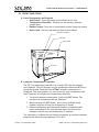
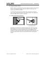
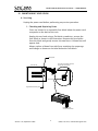
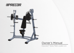
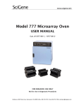
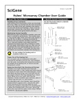
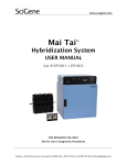
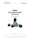
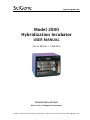
www.scigene.com Model 2000 Hybridization Incubator USER MANUAL Cat. #1040-50-1, 1040-50-2 FOR RESEARCH USE ONLY Not for Use in Diagnostic Procedures SciGene • 306 Potrero Ave, Sunnyvale, CA 94085 USA • 408-733-7337 • Fax 408-733-7336 • [email protected] Model 2000 Hybridization Incubator — USER MANUAL Serial Number The following serial number identifies the specific instrument you have purchased and must be referenced when requesting service. A copy is affixed to the instrument. Technical Service: (408) 733-7337, [email protected] Warranty SciGene warrants that the rotating oven described in this manual shall be free of defects in materials and workmanship for a period of 12 months from date of delivery. This warranty does not cover removable rotators or accessories including hybridization tubes. In the event of a defect during the warranty period, SciGene’s limit of liability will be to provide replacement parts at no charge or, at its sole discretion, replace the product. The foregoing warranty is void in the event the unit was abused or modified or used in a manner inconsistent with its intended purpose. SciGene makes no other warranty, expressed or implied including warranties of merchantability and fitness for a particular purpose. In no event shall SciGene be liable for any direct, indirect, special, incidental or consequential damages or for any damages resulting from loss arising out of or in connection with the sale, use or performance of the product. Copyright Copyright ©2004-2008 SciGene Corporation. All rights reserved. SciGene is a trademark of SciGene Corporation, Sunnyvale, CA. All other trademarks used in this manual are the property of their respective owners. Version 1.0, September 2007 1 (408) 733-7337, [email protected] Model 2000 Hybridization Incubator — USER MANUAL Table of Contents I. SAFETY NOTICES ........................................................................................................ 3 A. Warnings .....................................................................................................3 B. Cautions......................................................................................................3 C. Lifting and Moving the Unit .........................................................................3 II. UNPACKING AND SETTING UP YOUR OVEN ................................................... 4 A. Removing the Unit from the Carton .............................................................4 B. Parts Provided .............................................................................................4 C. Installation ..................................................................................................4 III. USING YOUR OVEN .................................................................................................... 5 A. Oven Components and Controls ..................................................................5 B. Using the Temperature Controller................................................................5 C. Calibrating the Temperature Controller .......................................................6 D. Using the Rotator Switch..............................................................................7 E. Loading and Removing Rotators ..................................................................7 IV. MAINTAINING YOUR OVEN .................................................................................... 8 V. A. Servicing .....................................................................................................8 B. Cleaning ......................................................................................................9 TROUBLESHOOTING................................................................................................10 VI. SPECIFICATIONS .......................................................................................................10 VII. TUBES, ROTATORS AND ACCESSORIES ..........................................................10 Version 1.0, September 2007 2 (408) 733-7337, [email protected] Model 2000 Hybridization Incubator — USER MANUAL I. SAFETY NOTICES A. Warnings Failure to comply with the following warnings that are affixed to the product can lead to possible personal injury or death. B. Cautions Failure to comply with the following cautionary statement affixed to the product may lead to possible personal injury. Items heated in the oven should be handled with heat protective gloves. Open all closed vessels heated in the oven with the opening pointed away from you to avoid contact with heated aerosols. C. Lifting and Moving the Unit The rotating oven you have purchased weighs approximately 35 lbs (16 kg). Use caution when lifting the unit to protect you and others from personal injury. Version 1.0, September 2007 3 (408) 733-7337, [email protected] Model 2000 Hybridization Incubator — USER MANUAL II. UNPACKING AND SETTING UP YOUR OVEN A. Removing the Unit from the Carton Open the shipping carton and remove the foam inserts from the top of the unit. Lift the unit from the shipping carton and place it on the bench. Carefully inspect the unit for damage. If there is evidence of damage, do not discard the shipping materials since they may be needed to return the unit. B. Parts Provided The items provided with the Model 2000 Hybridization Incubator are generally shipped in two boxes as follows: Large o o o o o Box (20” x 18” x 17”) Rotating Oven Power Cord User Manual Tube Gripper Standard 4/8 tube rotator Small Box (15” x 15” x 6”) o Stainless Steel Drip Pan (SciGene Cat. #1040-20-1) o One – 35 x 300 mm Hybridization Tube with Screw Cap Please verify that all items are received and are in good condition. C. Installation 1. Placement Place the unit on a stable, level surface within a few feet of the power source. Avoid locating it below a shelf where solutions are stored. A spill may enter the electrical compartment through the vent holes on the top of the unit and cause damage. Ensure there is adequate clearance along the front and right side of the oven to open the door completely. There should be a minimum clearance of 3 inches along the top and back panels for air circulation. 2. Removing Tie Wraps from Tube Rotator The oven is delivered with the tube rotator located inside the chamber. The rotator is fastened at each end with tie wraps. Carefully cut and remove the tie wraps using scissors or utility knife. 3. Connecting the Power Plug the power cord provided into the back of the unit and then to a properly grounded outlet. Use only the power cord provided. 4. Powering On Turn ON using the switch on the front of the oven. Version 1.0, September 2007 4 (408) 733-7337, [email protected] Model 2000 Hybridization Incubator — USER MANUAL III. USING YOUR OVEN A. Oven Components and Controls • Heat Switch -Turns ON power to the heater in the unit. • Temperature Controller - Used to set and observe chamber temperature • Rotator Switch -Turns on or momentarily moves (jogs) the rotator • Door Latch - Secures and seals the door to the cabinet Temperature Controller Heat Switch Rotator Switch SciGene WATLOW SD31 ON ROTATOR MODEL 2000 MICRO HYBRIDIZATION INCUBATOR ON OFF JOG Door Latch B. Using the Temperature Controller The SD-31 temperature controller has a single LED read out and four push buttons. The LED displays the set temperature when the SET key is pressed and held. Otherwise the ACTUAL chamber temperature is displayed. The push buttons are used to set the oven temperature and when required, to calibrate the temperature controller. 1. To set the chamber temperature, hold in the SET button. The previous set temperature will be displayed. 2. While pressing the SET button, press the up or down arrow buttons until the desired set temperature is shown. 3. Release the buttons and the actual chamber temperature will again be displayed. The unit will now adjust the heat of the chamber until the new set temperature is attained. The controller is calibrated at the factory to provide an accurate chamber temperature when operated between 35 to 99°C. Version 1.0, September 2007 5 (408) 733-7337, [email protected] Model 2000 Hybridization Incubator — USER MANUAL C. Calibrating the Temperature Controller The SD-31 temperature controller comes calibrated from the factory to provide accurate oven temperatures from 35 to 99°C. The temperature controller will require calibration only if: • When checking the oven temperature with a calibrated digital thermometer, the oven temperature differs by more than one degree (1°C) from the actual temperature shown on the controller display. An NIST calibrated digital thermometer (sold separately, SciGene Cat. #1051-52-0) is required to calibrate the unit. Follow these steps to adjust the controller to achieve accurate temperatures. 1. Set the temperature on the controller to 65°C and allow the temperature in the unit to stabilize. 2. Using the cable provided with the digital thermometer (SciGene Cat. #1051-52-0), plug one end into the blue receptacle found on the back panel of the unit and the other into the digital thermometer. 3. Turn on the thermometer using the ON/OFF button on the keypad. The temperature of the chamber will be displayed. 4. On the temperature controller, press the infinity key for three seconds until “OPEn” appears. 5. Press the down arrow four times until “CAL” appears. 6. Press and hold the set key. The existing offset value between the controller and digital thermometer is displayed. 7. Calculate the difference in the temperature shown on the controller and the digital thermometer; e.g. the controller displays 65°C and the digital thermometer displays 63.5°C, the difference is 1.5°C. 8. Press and hold the SET key and use the up and down arrows to enter the offset value calculated in Step #7. For example, if the controller displays a temperature that is 1.5°C higher than the digital thermometer, adjust the offset value to minus 1.5 (-1.5) of the current offset. 9. Press the Infinity Key (∞) to exit calibration. The chamber temperature is now calibrated for the set temperature you selected. Repeat the calibration process starting at Step 1 for the highest temperature for the range of temperatures you will be using. Version 1.0, September 2007 6 (408) 733-7337, [email protected] Model 2000 Hybridization Incubator — USER MANUAL D. Using the Rotator Switch Rotator motion is controlled using a three-position switch on the front of the unit. To engage the rotator, press the switch in at the top. The rotator moves at a fixed 6 RPM. To momentarily move (jog) the rotator when mounting or removing tubes, press and hold the switch in the down position. The rotator will move at 6 RPM until the switch is released. E. Loading and Removing Rotators Place end of shaft on left bearing Insert shaft ball with alignment pin into right bearing All rotators are loaded and removed using the same two-step process. When loading, first insert the end of the shaft that ends in a ball joint with alignment pin into the slotted bearing on the right wall of the chamber. The left end of the shaft is then placed into the bearing on the left side of the chamber. Reverse this procedure when removing the rotator. Version 1.0, September 2007 7 (408) 733-7337, [email protected] Model 2000 Hybridization Incubator — USER MANUAL IV. MAINTAINING YOUR OVEN A. Servicing Unplug the power cord before performing any service procedure. 1. Checking and Replacing Fuses Fuses are located in a removable fuse block below the power cord receptacle on the back of the unit. Unplug the cord and using a flat blade screwdriver, remove the fuse block as shown in the illustration. Remove the fuse holder from the block and gently remove the two fuses. A blown fuse will appear dark. Always replace a blown fuse with fuses matching the amperage and voltage as shown on the label below the fuse block. Main power Use small screwdriver behind tab to open fuse block Back of unit Fuse block Digital thermometer jack Push clip up to release fuse holder Version 1.0, September 2007 8 (408) 733-7337, [email protected] Model 2000 Hybridization Incubator — USER MANUAL 2. Replacing the Temperature Controller If the actual temperature reported on the controller is erratic after calibration, the temperature controller may need to be replaced. Please contact the SciGene Technical Service Department ([email protected]) for assistance in troubleshooting. If needed, replacement controllers are available (SciGene Cat. #RP600-0146-02). 3. Rotator Drive System The rotator drive system is designed to provide trouble-free operation for many years and does not require routine maintenance. However, components of the drive system that fail due to normal wear and tear over long-term usage can be easily replaced. Contact SciGene’s Technical Service Department ([email protected]) to obtain replacement parts and perform these repairs. B. Cleaning • • • Clean the exterior and interior surfaces using a mild, detergentbased spray cleaner and wipe with a soft cloth. Under no circumstances should solutions be allowed to enter the electronics package through the ventilation slots on the top of the unit. Do not use abrasive cleansers or scouring pads that can scratch the stainless steel. Version 1.0, September 2007 9 (408) 733-7337, [email protected] Model 2000 Hybridization Incubator — USER MANUAL V. TROUBLESHOOTING Symptom Rotator does not turn after closing door Temperature is erratic Cause Rotator control is in the off position Thermal controller is defective Solution Press switch at top. Replace controller VI. SPECIFICATIONS Electrical (Oven Unit) Cat. #1040-50-1 Cat. #1040-50-2 Dimensions Interior Chamber Exterior 115/120V AC; 50/60 Hz; 350W 220/240V AC; 50/60 Hz; 350W 14W 36W 16W 42W x x x x 8D x 13H inches 19D x 21H cm 14D x 13H inches 35D x 33H cm Weight Net 35 lbs (16kg) Gross 45 lbs (20kg) Includes shipping carton Performance and Controls Temperature Range Ambient +5°C to 99°C Temperature Regulation ± 0.2°C Heat up Time >5°C per minute Temperature Controller Digital PID, single loop Temperature Display Actual or Set single LED Digital Thermometer Output Thermocouple Temperature Range Ambient +5°C to 99°C Temperature Regulation ± 0.2°C VII. TUBES, ROTATORS AND ACCESSORIES Cat. # 1040-01-0 1040-02-0 1040-51-1 1051-52-0 Description Hybridization tube, 35x30mm with screw cap Hybridization tube, 35x150mm with screw cap Rotator for 4 large or 8 small hybridization tubes Handheld digital thermometer. Includes cable and NIST certificate. UoM Each Each Each Each Version 1.0, September 2007 10 (408) 733-7337, [email protected]