1
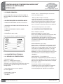
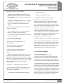
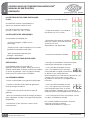
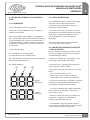
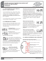
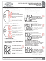
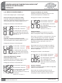
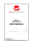
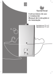
MICROCOM®
I Controlador de Temperatura
Manual de Instruções
CONTROLADOR DE TEMPERATURA MICROCOM®
MANUAL DE INSTRUÇÕES
ÍNDICE
1 INTRODUÇÂO
1.1 1.2 1.3 1.3.1 1.3.2 1.3.3 1.3.4 Funções Principais Especificações do Controlador Características Técnicas
Medição da Temperatura
Controle da temperatura
Saída de Potência
Outras funções
Pg. 2
Pg. 2
Pg. 2
Pg. 2
Pg. 2
Pg. 3
Pg. 3
2 OPERAÇÃO
2.1 2.2 2.3 2.4 2.5 2.5.1 2.5.2 2.5.3 2.5.4 2.5.5 2.5.6 2.6
2.6.1 2.6.2 Requisitos para Instalação e Operação Considerações de Segurança
Instruções de Instalação
Operação inicial
Modo de operação do controlador Descrição
Tela de Repouso
Modo de operação “Click & Rotate” Procedimento de travamento do botão “Click & Rotate”
Descrição dos Alarmes
Menu de interface do operador
Menu Principal
Menu de configuração 1
Menu de Configuração 2
Pg. 4
Pg. 4
Pg. 4
Pg. 4
Pg. 5
Pg. 5
Pg. 5
Pg. 5
Pg. 6
Pg. 6
Pg. 6
Pg. 7
Pg. 8
Pg. 9
3 Solução de Problemas
3.1 Solução de problemas
3.1.1 Tabela de Falhas
Pg. 11
Pg. 11
4 Garantia
4.1
Garantia Pg. 12
5 Contato
5.1 5.2 www.incoe.com
Serviço Global Escritórios Globais
Pg. 14
Pg. 15
©INCOE® CORPORATION 3/2010
Pg. 1
CONTROLADOR DE TEMPERATURA MICROCOM®
MANUAL DE INSTRUÇÕES
INTRODUÇÃO
1
1.1 FUNÇÃO PRINCIPAL:
O controlador de temperatura MICROCOM® foi
desenvolvido para controlar sistemas de câmara
quente.
1.2 ESPECIFICAÇÕES DO CONTROLADOR:
• TENSÃO DE ENTRADA: 230 VAC monofásico
• VARIAÇÃO DA TENSÃO DE ENTRADA: 207 VAC
até 253 VAC.
• POTÊNCIA MAXIMA DE SAIDA: 3600W.
(15 Amps).
• FREQUÊNCIA: 60hz / 50hz.
Uma etiqueta fixada no gabinete indicando:
1.3 CARACTERÍSTICAS TÉCNICAS:
1.3.1 MEDIÇÃO DA TEMPERATURA:
• Termopares tipo J
(leitura “J” no display) ou tipo K
(leitura “nl” no display), isolados ou
aterrados, com compensação automática de junta
fria (seleção do tipo de termopar no menu de
configuração).
• Intervalo de Leituras, 83 ms @ 60 Hz
ou 10 ms @ 50hz.
•Escala °F ou °C (selecionável pelo usuário no
menu de configuração)
• Detecção de termopar invertido
(não envia tensão para a resistência, saída 0%).
• Detecção automática de termopar aberto,
troca automaticamente para modo manual mantendo o ultimo percentual de potencia enviado
para a resistência (ajustável através do software).
• Alarmes de temperatura alta e baixa
1.3.2 CONTROLE DA TEMPERATURA:
São 2 modos de controle:
MODO AUTOMATICO (closed loop):
Esta é uma unidade automática de controle (PID).
O controlador monitora continuamente o
comportamento da resistência à qual está conectado. O controlador adapta sua saída de potencia
à resistência automaticamente, definindo os
parâmetros P.I.D.
MODO MANUAL (open loop):
Neste modo, o controlador envia o percentual de
potência salvo na memória como padrão para o
modo manual (valor padrão: 20%). Note que este
valor pode ser modificado somente na tela de
repouso. Quando o controlador esta em modo
MANUAL, os alarmes de temperatura alta e baixa
não estão ativos. O mesmo vale para a função
“SoftStart”.
FASE DE INICIO (“Fase SoftStart”):
Esta função foi projetada para prevenir falhas no
inicio à frio e prolongar a vida útil das resistências.
Ela elimina o choque térmico durante a transição
de frio para quente.
Esta função também remove qualquer
umidade que possa estar contida na resistência
através aplicação de baixa potencia ou pelo
aumento progressivo aplicada na resistência.
• Precisão de +/- 0.5% na
faixa de 32 to 932 °F
(0 - 500°C).
Pg. 2
© INCOE® CORPORATION 3/2010
www.incoe.com
CONTROLADOR DE TEMPERATURA MICROCOM®
MANUAL DE INSTRUÇÕES
INTRODUÇÂO
Existem 2 tipos de “Fase SoftStart”.
• Duração da Rampa: Aquecimento com
potência máxima limitada a 15% pelo período
de 5 minutos ou até a temperatura máxima de
212°F (100°C).
• VARIAÇÂO DA RAMPA: Aplica uma variação
de temperatura expressa em °F / min. ° (ou °C /
min. ) até a temperatura selecionada pelo
usuário.
Os dois tipos de rampa podem ser ativados nas
seguintes condições:
• Se a unidade estiver em modo automático
durante a seqüência de inicio de uso.
• Caso o usuário alterne do modo manual para
o modo automático.
1
• Sistema anti arco.
• Detecção de TRIAC em curto.
• Problemas na Resistência ou carga.
• Problemas na Resistência ou carga:
detecção automática pela medição da corrente.
Detecção determinada na seguinte condição:
Caso a corrente medida seja 0 e o sistema esteja
enviando corrente. O controlador mostra a mensagem “Otr” (Resistência ou TRIAC aberto)
• Detecção automática TRIAC em curto:
a detecção é determinada pela seguinte condição:
Caso a medição da corrente seja diferente de 0 e
o controlador não esteja enviando potencia (% de
potencia=0). O controlador então mostra a
mensagem ”Str” (TRIAC em curto).
1.3.3 SAIDA DE POTÊNCIA:
• Detecção automática de variação da Resistência:
• Saída de tensão via TRIAC de 15 A
(BTA24 800V).
Após um período de estabilização de 120 segundos na temperatura selecionada, o sistema efetua
uma medição e salva o valor da resistência (em
Watts). O controlador mostra um alarme
(Mensagem “Hra”) caso ocorra uma variação de
pelo menos 20% em relação ao valor salvo.
• Dupla proteção de sobrecarga via
fusível (Ref.: FA15 ou ABC-15).
• Proteção contra variação de tensão
(Chave de proteção calibrada para
275V).
• Modos de variação do Angulo de fase ou “zero
crossing” (selecionável pelo usuário no modo
de configuração). Esta escolha é valida somente
durante a fase de controle. Durante a fase “SoftStart”, o controlador permanece em modo “ângulo
de fase” independentemente do modo
selecionado.
• Precisão: +/- 1% da temperatura nominal.
• Segurança de carga: Rele comandado por software. O rele corta a tensão para a resistência
nas seguintes condições:
• Controlador desligado pelo botão ON/OFF
www.incoe.com
1.3.4 OUTRAS FUNÇÕES:
• Correção de voltagem
(Patente INCOE® 6,107,610 - USA):
o sistema utiliza um segundo circuito fechado
de controle, o qual mantém a tensão aplicada à
resistência caso ocorra uma variação na linha. O
sistema está ativo para voltagens de ate 190 VAC.
• Pino de detecção Anti Arco: O controlador pode
detectar automaticamente a presença de um pino
“Anti Arco” no conector do gabinete. Quando este
pino é detectado, o sistema é ativado e permite
cortar a alimentação do TRIAC, assim como, cortar
o rele de proteção, quando o controlador é removido do gabinete. O tempo de resposta para isso e
menor que 20 µsec. Caso o pino não seja detectado, o sistema simplesmente não é ativado.
©INCOE® CORPORATION 3/2010
Pg. 3
CONTROLADOR DE TEMPERATURA MICROCOM®
MANUAL DE INSTRUÇÕES
OPERAÇÃO
2
2.1 PRÉ-REQUISITOS PARA INSTALAÇAÕ
E USO:
• O tipo de controlador (World).
O modulo de controle é projetado para
operar em ambiente industrial seco.
Faixa de temperatura de trabalho:
de 14°F a +158°F ou -10°C a +70°C.
• O tipo de termopar e a unidade de
temperatura (F ou C) usada.
2.2 REQUISITOS DE SEGURANÇA:
O controlador é protegido por:
• Fusíveis protegem o TRIAC contra
sobrecarga.
• A freqüência da fonte de energia da
fábrica e o status da função anti-arco
(sistema anti-arco
detectado ou não detectado).
• Proteção contra sobre voltagem caso a alimentação do controlador exceda 275V.
• Rele de proteção projetada para
proteger a Resistência.
• A versão do software instalado.
2.3 INSTRUÇÕES PARA INSTALAÇÃO:
INSTALACAO:
O controlador pode ser instalado em
gabinetes industriais padrão. Antes de instalar o
modulo controlador, certifique-se de que o modulo
se ajuste ao gabinete. Caso haja alguma dúvida,
favor entrar em contato com a INCOE®.
2.4 OPERAÇÃO INICIAL
• Instale o controlador num gabinete apropriado.
• Conecte o cabo de alimentação do gabinete à
fonte de energia da fábrica.
• Confira toda a fiação de entrada e saída do
gabinete.
• Uma vez conectado à fonte de energia da fábrica,
ligue o gabinete usando s chave geral do disjuntor
do gabinete.
• Inicialmente, a tela mostrará o status como
mostrado aqui:
Pg. 4
© INCOE® CORPORATION 3/2010
• Para ligar o controlador, mantenha o botão
rotativo pressionado por 3 segundos.
• Caso a tela do controlador mostre
“otc”, isso significa que o termopar
está quebrado ou ligado incorretamente. Neste caso o controlador não
libera voltagem para a Resistência (Exceto se o parâmetro “otc” esteja com o valor “ON”).
O problema necessita ser corrigido antes de
continuar.
• Caso a tela do controlador mostre
“rtc”, isso significa que o termopar
está invertido. Neste caso, o controlador não libera voltagem para a resistência. O
problema precisa ser corrigido antes de continuar.
• Caso a temperatura inicial seja inferior a 212°F
ou 100°C, o SoftStart é ativado.
Em caso de problemas durante o inicio da
operação, consulte o capitulo
“Solucao de Plroblemas” pagina 11
www.incoe.com
CONTROLADOR DE TEMPERATURA MICROCOM®
MANUAL DE INSTRUÇÕES
OPERAÇÃO
2.5 MODO DE OPERAÇÃO DO CONTROLADOR:
2.5.1 DESCRIÇÃO:
Este controlador consiste no seguinte:
Um botão “CLICK & ROTATE” para entrada de
dados e visualização.
Duas telas (Displays) de 3 dígitos (7 segmentos +
DP), o mostrador superior é vermelho (usado para
mostrar temperaturas, alarmes e parâmetros), o
mostrador inferior é verde (usado para mostrar a
temperatura programada e os vários valores dos
parâmetros).
2.5.2 TELA EM REPOUSO
Em modo de operação normal, o mostrador
superior mostra a temperatura atual,
enquanto o mostrador inferior mostra a
temperatura programada.
Caso ocorra uma falha ou alarme, isso será
mostrado no mostrador superior. As funções
“ON / Off” e “Aumentar / Reduzir” são as
únicas disponíveis na tela de repouso
(Standby).
Os 3 indicadores (LED) serão mostrados
apenas no mostrador superior.
3 Sinais de LED (DP): 2.5.3 MODO DE OPERAÇÃO DO BOTÃO
“CLICK & ROTATE”:
#1 : Auto/Manual, quando ligado,
o controlador esta em modo manual
Um único botão é usado para realizar varias
tarefas. Este botão processa varias funções
como detalhadas abaixo:
#2 : Indicador de taxa de aquecimento (mostrador
do percentual de potencia).
• Pressionar o botão por 3 segundos = Liga
ou Desliga o controlador (ON / OFF)
#3 : Modo SoftStart.
• Pressionar por 5 segundos para destravar,
caso esteja em modo travado.
#1
#2
#3
2
• Um duplo clique permite acessar ou sair do
menu.
Obs.: Da tela de repouso: um
duplo clique entra no menu principal,
outro duplo clique sai do menu principal.
Dígitos
Superiores
Dígitos
inferiores
• Pressionar o botão por 2 segundos = permite
selecionar um parâmetro (Parâmetro ficara
piscando) e a modificação do mesmo.
• Caso um parâmetro tenha sido modificado,
outro clique de 2 segundos é necessário
para salvar o valor.
• Aumentar / Diminuir (Girar para direita ou
esquerda) = modifica os parâmetros e
navega pelos diferentes menus.
• O controlador volta ao modo de repouso
caso o botão “Click & Rotate” permaneça sem
nenhuma operação por 5 segundos.
www.incoe.com
©INCOE® CORPORATION 3/2010
Pg. 5
CONTROLADOR DE TEMPERATURA MICROCOM®
MANUAL DE INSTRUÇÕES
OPERAÇÃO
2
2.5.4 PROCEDIMENTO PARA TRAVAR O
BOTÃO “CLICK & ROTATE”:
Caso o parâmetro “LOC” esteja com o valor
“ON” (no menu de configuração 2, pagina 9),
o botão travará automaticamente após 30
segundos de inatividade. Para destravar
temporariamente o botão, pressione o botão
por 5 segundos.
Caso o botão esteja travado e não pressionado,
será mostrada a mensagem “LOC”.
2.5.5 DESCRIÇÃO DE ALARMES:
Alarmes e falhas são mostrados apenas na tela
de repouso (Standby), tanto de maneira fixa ou
alternada com o valor da temperatura, como
mostrado abaixo:
Termopar aberto:
• Esta falha é mostrada de forma
continua na tela de repouso.
Termopar Inverso:
• Esta falha é mostrada de forma
continua na tela de repouso
Resistência Desconectada:
• Esta falha é mostrada de forma
alternada com a temperatura. Uma
resistência aberta é detectada
automaticamente por medição
de corrente. Caso a corrente medida seja 0 e o
percentual de potencia seja maior que 0, isso é
detectado como uma falha da resistência.
Falha de curto no TRIAC:
• Esta falha é mostrada
de forma alternada com
a temperatura. Um TRIAC
em curto é detectado
automaticamente caso a corrente medida seja
diferente de 0 e o percentual de potencia
seja =0.
Pg. 6
© INCOE® CORPORATION 3/2010
Variação da potencia da resistência:
• Esta falha é mostrada de forma
alternada com a temperatura. A
detecção automática de variação
da potencia nominal da resistência. Depois de 120
segundos de atingida a estabilidade do controle da
temperatura (temperatura +/- 3 °F / °C da temperatura
programada), o sistema mantém a potencia nominal
na memória e ativa um alarme caso ocorra uma
variação superior a 20% em relação a potencia
nominal.
Alarme de temperatura Alta:
• Esta falha e mostrada de forma
alternada com a temperatura.
Este alarme é mostrado quando a
temperatura estiver mais alta do que a temperatura
programada + o valor do parâmetro “HIGH”
(Ajustável no menu de configuração 1,
pagina 8).
Alarme de temperatura Baixa
• Esta falha e mostrada de forma
alternada com a temperatura. Este
alarme e mostrado quando a temperatura esta mais
baixa do que a temperatura programada. O valor do
parâmetro “LOW”
(ajustável no menu de configuração 1, pagina 8).
2.5.6 MENU DE INTERFACE COM O OPERADOR:
Visão geral da organização do Menu.
Menu Principal (Duplo clique para entrar ou sair).
Seleção do modo de controle
Mostrador de percentual de
potencia aplicada
Mostrador da potencia instalada da
resistência
Mostrador da medição de corrente
Seleção do menu de configuração
(Pressione 2 segundos para modificar,
rotacione para selecionar 1 ou 2,
pressione por 2 segundos novamente para confirmar).
www.incoe.com
CONTROLADOR DE TEMPERATURA MICROCOM®
MANUAL DE INSTRUÇÕES
OPERAÇÃO
Mostrador do percentual de potencia aplicado a
Resistência:
Em modo manual, o valor no mostrador
corresponde ao percentual programado
manualmente.
Navegação via botão “Click & Rotate”:
CFG 1 Menu (Duplo clique para sair).
Selecionar Alarme High
(temperatura alta)
Selecionar Alarme Low
(Temperatura baixa)
Selecionar Temperatura Máxima
de trabalho
Selecionar temperatura mínima
de trabalho
Se mostrador “Aumentar”
Se mostrador “Diminuir”
Se “Selecionado” (Pressione
por 2 segundos): Sem efeito.
Valor em %.
Selecionar tempo de rampa
Selecionar variação da rampa
Mostrador de Potencia Instalada:
Navegação via botão “Click & Rotate”:
CFG 2 Menu (Duplo clique para sair).
2
Se mostrador “Aumentar”
Seleção da unidade de
temperatura
Se mostrador “Diminuir”
Se “Selecionado” (Pressione
por 2 segundos): Sem efeito.
Valor em Watts.
Seleção do tipo de termopar
Seleção do tipo de saída
Modo de operação em caso de
falha do termopar
Mostrador de Corrente:
Navegação via botão “Click & Rotate”:
Parâmetros de inicialização do
controlador
Trava do controlador habilitada
Estado do controlador em
reinicio
Se mostrador “Aumentar”
Se mostrador “Diminuir”
Se “Selecionado” (Pressione
por 2 segundos): Sem efeito.
Valor em Amperes.
2.6 MENU PRINCIPAL:
O menu principal é como segue:
Seleção do Menu de Configuração:
Seleção do modo de controle AUTO ou MANUAL
(AUTO por padrão):
Selecionando parâmetros no menu de
configuração (caso a configuração selecionada
não corresponda com nenhum menu, então
nada acontece com a validação).
Navegação via botão “Click & Rotate”:
Se mostrador “Aumentar”
Se mostrador “Diminuir”
Se “Selecionado” (Pressione
por 2 segundos): Será possível
modificar o valor do parâmetro
e escolher AUTO ou Manual.
Confirme a escolha
pressionando novamente por 2
segundos.
www.incoe.com
Navegação via botão “Click & Rotate”:
Se mostrador “Aumentar”
Se mostrador “Diminuir”
Se “Selecionado” (Pressione
por 2 segundos): Será possível
modificar o valor do parâmetro
e escolher 1 ou 2. Confirme
a escolha pressionando
novamente por 2 segundos.
©INCOE® CORPORATION 3/2010
Pg. 7
CONTROLADOR DE TEMPERATURA MICROCOM®
MANUAL DE INSTRUÇÕES
OPERAÇÂO
2
2.6.1 MENU DE CONFIGURAÇÂO 1:
Temperatura Mínima de Trabalho:
Parâmetro ajustável usado para limitar o valor
mínimo da temperatura. (Padrão 0°C)
O menu de configuração 1 e como segue:
Selecionar Alarme de Temperatura Alta:
O correto ajuste deste parâmetro permite
determinar o desvio máximo da temperatura para
acionamento do alarme (Valor padrão: 5°F/°C)
Navegação via botão “Click & Rotate”:
Se mostrador “Aumentar”
Se mostrador “Diminuir”
Navegação via botão “Click & Rotate”:
Se mostrador “Aumentar”
Se mostrador “Diminuir”
Se “Selecionado” (Pressione
por 2 segundos): Será possível
modificar o valor do parâmetro.
Valor em °F / °C
Esta rampa e ativada se a temperatura, durante
o inicio da operação é mais baixa que 212°F
(100°C). O controlador irá manter a potencia
de aquecimento em 15% durante o período
definido pelo operador (de 0 a 99 min.)
(Padrão 5 min).
Navegação via botão “Click & Rotate”:
Se mostrador “Diminuir”
Se “Selecionado” (Pressione
por 2 segundos): Será possível
modificar o valor do parâmetro.
Valor em °F / °C
Temperatura Máxima de Trabalho
Selecionável pelo Usuário:
Parâmetro ajustável usado para limitar o valor
Maximo da temperatura. (Padrão 500°C)
Se mostrador “Diminuir”
Se “Selecionado” (Pressione
por 2 segundos): Será
possível modificar o valor do
parâmetro.
Valor em °F ou em °C
Pg. 8
© INCOE® CORPORATION 3/2010
Este tempo será salvo na memória e usado em
todos os inícios de operação. Nota: O tempo de
rampa não pode ser modificado ou cancelado
durante a operação.
Navegação via botão “Click & Rotate”:
Se mostrador “Aumentar”
Se mostrador “Diminuir”
Se “Selecionado” (Pressione
por 2 segundos): Será
possível modificar o valor do
parâmetro. Valor mostrado em
minutos.
Navegação via botão “Click & Rotate”:
Se mostrador “Aumentar”
Se “Selecionado” (Pressione
por 2 segundos):
Será possível modificar o valor
do parâmetro.
Valor em °F ou em °C
Tempo de Rampa:
Parâmetro ajustável que permite ao usuário
definir o tempo de rampa da função Softstart.
Low alarm:
O correto ajuste deste parâmetro permite
determinar o desvio mínimo da temperatura para
acionamento do alarme (Valor padrão: 5°F/°C).
Se mostrador “Aumentar”
Variação da Rampa:
Parâmetro ajustável usado para definir o Segundo
modo da função Softstart.
Este modo será ativado quando o valor do
parâmetro for diferente de 0. Este parâmetro é a
variação da rampa. (Padrão: 0°F ou 0°C/min.).
www.incoe.com
CONTROLADOR DE TEMPERATURA MICROCOM®
MANUAL DE INSTRUÇÕES
OPERAÇÂO
Tipo do termopar:
Este parâmetro permite a seleção do tipo
termopar usado. Termopares tipo J ou tipo K
(mostrado como “nl”). O termopar padrão é do
tipo J.
A cada minuto, a temperatura será aumentada um
certo numero de graus (0 a 99°F/min. ou °C/min.),
e o percentual de potencia nominal não e limitado.
Quando a temperatura atinge o programado,
a rampa esta completa. Esta duração depende
da variação entre a temperatura programada e
a temperatura atual e da variação por minuto
programada.
Navegação via botão “Click & Rotate”:
Se mostrador “Aumentar”
Enquanto a rampa esta operando, é possível
modificar a temperatura programada, o que
permite ajustes quando a temperatura estiver
abaixo ou acima da programada.
Se “Selecionado” (Pressione
por 2 segundos): Será
possível modificar o valor do
parâmetro.
Termopar J / Termopar K
(mostrado como “nl”).
Navegação via botão “Click & Rotate”:
Se mostrador “Diminuir”
Se mostrador “Diminuir”
Exemplo:
Temperatura inicial = 30°C, temperatura
programada = 300°C, Variação da rampa = 30°C/min.
A rampa durará 9 minutos,
porque (300-30)/30=9 degraus de 30°C.
Se mostrador “Aumentar”
2
Se “Selecionado” (Pressione
por 2 segundos): Será possível
modificar o valor do parâmetro.
Valor em °F/min ou °C/min.
Selecionar o tipo de saída:
Este parâmetro permite selecionar o tipo de
saída de potencia, Ângulo de fase (PhA) ou “Zero
Crossing” (0Cr). Esta seleção é valida apenas
durante a fase de controle. Durante a fase de
SoftStart, o controlador trabalha em modo de
ângulo de fase.
Navegação via botão “Click & Rotate”:
Se mostrador “Aumentar”
2.6.2 MENU DE CONFIGURAÇÔ 2:
Se mostrador “Diminuir”
O menu de configuração 2 é como segue:
Se “Selecionado” (Pressione
por 2 segundos): Será
possível modificar o valor do
parâmetro. Valor em Ângulo
de Fase (PhA) ou em zero
crossing (0Cr).
Unidade de Temperatura:
Este parâmetro permite a seleção da unidade de
temperatura, em °C ou °F.
Navegação via botão “Click & Rotate”:
Se mostrador “Aumentar”
Se mostrador “Diminuir”
Se “Selecionado” (Pressione
por 2 segundos): Será possível
modificar o valor do parâmetro.
Valor em °F ou °C.
www.incoe.com
Modo de operação em falha do termopar:
O percentual de potencia é salvo
na memória durante a fase de controle,
quando estabilizado.
(temperatura estável +/- 3° da temperatura
programada, por pelo menos 2 minutos).
©INCOE® CORPORATION 3/2010
Pg. 9
CONTROLADOR DE TEMPERATURA MICROCOM®
MANUAL DE INSTRUÇÕES
OPERAÇÂO
2
Navegação via botão “Click & Rotate”:
Caso o parâmetro esteja selecionado como
“OFF”, o controlador mostra um alarme “otc”
e não aplica nenhuma voltagem à Resistência
quando uma falha do termopar ocorre.
Se mostrador “Aumentar”
Se mostrador “Diminuir”
Caso o parâmetro esteja selecionado para
“ON”, quando ocorre uma falha do termopar,
o controlador muda automaticamente para
modo MANUAL, modifica o percentual
manual para o percentual salvo e aplica este
percentual de potencia na resistência.
Se “Selecionado” (Pressione
por 2 segundos): Será
possível modificar o valor do
parâmetro.
Navegação via botão “Click & Rotate”:
Se mostrador “Aumentar”
Se mostrador “Diminuir”
Se “Selecionado” (Pressione
por 2 segundos): Será
possível modificar o valor do
parâmetro.
Estado do Controlador em re-inicio:
Este parâmetro permite a seleção do estado do
controlador quando a chave geral e ligada, ou a
energia restabelecida. Caso o parâmetro estiver
programado para “OFF” e a fonte de energia for
desligada, o controlador irá reiniciar em modo
“OFF” quando a energia for restabelecida.
Parâmetros de inicialização do controlador:
Este parâmetro permite que todos os parâmetros
de fábrica sejam restaurados.
Caso o parâmetro esteja programado para “ON” e
a fonte de energia for desligada, o controlador
reiniciará em modo “ON” quando a energia
for restabelecida. Caso o parâmetro esteja
programado para “AII” e a fonte de energia for
desligada, o controlador irá reiniciar no modo em
que estava antes do desligamento da energia.
Navegação via botão “Click & Rotate”:
Navegação via botão “Click & Rotate”:
Se mostrador “Aumentar”
Se mostrador “Aumentar”
Se mostrador “Diminuir”
Se mostrador “Diminuir”
Se “Selecionado” (Pressione
por 2 segundos):
Será possível modificar o valor
do parâmetro.
Trava do controlador:
Este parâmetro permite habilitar ou desabilitar
a trava do controlador. Por padrão, este
parâmetro esta programado para OFF. Caso esteja
programado para ON, o botão “Click and Rotate”
trava toda vez que fica inativo por 30 segundos.
Para destravar temporariamente o botão, basta
pressionar o botão por 5 segundos.
Pg. 10
© INCOE® CORPORATION 3/2010
Se “Selecionado” (Pressione
por 2 segundos): Será
possível modificar o valor do
parâmetro.
Valores do parâmetro: OFF, ON
ou AII (Como seja).
www.incoe.com
CONTROLADOR DE TEMPERATURA MICROCOM®
MANUAL DE INSTRUÇÕES
Solução de Problemas
3
Falha
Efeitos /
Ferramentas
Mostrador
Proteções
Soluções
Termopar aberto
Temperatura
Diminui.
A tela de repouso
mostra continuamente a
mensagem “otc”.
Comando doTRIAC
Desconecta e
para o aquecimento.
Teste o termopar com um
micro, troque para modo
manual.
Termopar
“Mordido”
Superaquecimento.
A tela de repouso mostra a
mensagem “LoA” alternadamente com a temperatura
Conserte o cabo ou
troque para modo manual
caso não possua tempo.
Termopar
Invertido
Temperatura
Diminui.
A tela de repouso mostra
permanentemente a
mensagem “rtc”.
Confira as conexões
elétricas,
Troque para modo
manual.
Variações de
Temperatura
A temperatura atual
não estabiliza.
A tela de repouso mostra a
mensagem “LoA” ou “HiA”
alternadamente com a
temperatura.
Material com problema.
Resistência
Desconectada
Temperatura
diminui.
Resistência
parcialmente
desconectada
Molde com problema.
Verifique as conexões
Troque o cartucho.
Umidade muito alta:
seque a Resistência
e, se necessário, troque-a
A tela de repouso mostra a
mensagem “LoA” alternadamente com a temperatura.
A temperatura atual cai no
display.
Resistência
Aterrada
A tela de repouso mostra a
mensagem “Otr” alternadamente com a temperatura. O
valor da temperatura diminui.
Troque o fusível de 16 A
Comando do TRIAC
desconecta e
para o aquecimento,
fusível de 16 A queima.
Resistência
Umidade muito alta:
seque o cartucho
e, se necessário, troque-o.
TRIAC em curto
Resistência
superaquece.
A tela de repouso mostra a
mensagem “Str” alternadamente com a temperatura. A
temperatura aumentara sem
controle inclusive em modo
Manual.
Queima de fusível
de 16 A na zona
com falha
A Resistência localizada no molde não
aquece
A tela de repouso mostra a
mensagem “Otr” alternadamente com a temperatura.
A temperatura programada
diminui.
Troque o fusível problemático.
A tela de repouso mostra a
mensagem “HiA” alternadamente com a temperatura.
Verifique o percentual de
potencia usado,
Se for 99,9%, Maximo do
controlador,
então o termopar esta
em curto ou a resistência
esta com problemas de
conexão elétrica.
Controlador
aquecendo sem
controle
TRIAC em curto
TRIAC desconecta e para
o aquecimento.
Envie o controlador para
a INCOE para reparo.
Verifique toda a fiação e a
resistência ôhmica das
resistências.
O controlador não
acende quando o
gabinete e ligado.
www.incoe.com
Sem aquecimento
Sem mensagens.
Sem saída de potencia.
Confira os fusíveis
localizados na placa de
circuito do controlador.
©INCOE® CORPORATION 3/2010
Pg. 11
4
CONTROLADOR DE TEMPERATURA MICROCOM®
MANUAL DE INSTRUÇÕES
Garantia
INCOE® Corporation – GENERAL TERMS AND CONDITIONS OF SALE
1 Applicable Law and Jurisdiction
These general terms and conditions apply to all proposals and quotations submitted by Seller, to all
purchase orders received by Seller, and to all goods and services sold by Seller, except as otherwise specifically provided in a document signed by Seller. This sale or any sale resulting herefrom
consists only of these terms and conditions and those in other documents which are referred to
herein or are attached hereto or in a document subsequently signed by Seller and referencing this
transaction (all of which constitute the “Agreement“). THE AGREEMENT SHALL BE GOVERNED,
CONSTRUED AND ENFORCED UNDER THE LAW OF THE STATE OF MICHIGAN INCLUDING
THE UNIFORM COMMERCIAL CODE IN FORCE ON THE INITIAL DATE OF THE AGREEMENT
(“UCC“), EXCEPT AS PROVIDED HEREIN. The U.N. Convention on the International Sales of
Goods shall not apply. Any services to be provided hereunder, whether or not they are otherwise
ancillary to and part of a sale of goods (as separate units), shall be considered ancillary to a sale of
goods and the UCC shall apply to all goods and services to be provided hereunder (“Goods“). THE
COURTS OF MICHIGAN SHALL HAVE EXCLUSIVE JURISDICTION OVER THE PARTIES AND
THE CLAIMS ARISING UNDER OR RELATED TO THE AGREEMENT. The parties stipulate to the
convenience of Michigan courts in general, and Oakland Circuit Court in particular, as to all litigation.
Any declaration of unenforceability of a provision shall be as narrow as possible and shall not affect
the enforceability of the other provisions.
2 Formation, Integration and Modification
A. The Agreement supersedes all previous quotations and agreements pertaining to the Goods.
Delivery to Seller of the Buyer‘s acceptance of a Seller’s quotation (according to its terms), Seller‘s
actions in reliance on Buyer‘s oral acceptance of a written or oral quotation, or Buyer‘s receipt of
the Goods, will constitute a binding contract under the terms of the Agreement. The Agreement is
subject to Seller‘s revocation or cancellation without liability until it is approved by Seller at its home
office. Notice of such approval may be furnished to the Buyer in the form of an acknowledgment,
shipment, or other form of express approval.
B. An order submitted by Buyer orally or in a purchase order or other writing (whether or not it
contains terms or conditions modifying, adding to, repugnant to, or inconsistent with these Terms
and Conditions), may be accepted, approved or filled by Seller, but any resulting contract and the
liabilities or obligations of Seller shall be determined solely by the Agreement, and (unless the Seller
otherwise advises Buyer in writing) notice is hereby given that Seller objects to any such terms or
conditions in Buyer‘s purchase order or other writing. Seller shall not be deemed to have in any way
enlarged or modified its liabilities or obligations under the Agreement by filling such order or by failing
to further object to Buyer‘s terms or conditions.
C. The Agreement is a final, complete and exclusive statement of the Agreement of the parties. THE
SELLER IS WILLING TO NEGOTIATE WRITTEN CHANGES TO THESE TERMS AND CONDITIONS,
BUT RESERVES THE RIGHT TO MAKE AN ADJUSTMENT IN THE PRICE OF THE GOODS. No
modifications, limitations, waivers or discharge of the Agreement or any of its terms shall bind Seller
unless in writing and signed by Seller‘s authorized employee at its home office. Notwithstanding
anything to the contrary in this Agreement, no modifications, limitation, waiver or discharge of any
provision of the Agreement shall affect the Buyer‘s liabilities to Seller accrued prior thereto. Seller may correct unilaterally any mathematical and typographical errors in the Agreement. Typed
provisions of the Agreement take precedence over printed provisions. A course of performance,
course of dealing, or customs in the trade shall not constitute a modification or waiver by Seller of
any right by Seller.
D. The Agreement is only for the benefit of the parties, except all disclaimers and limitations applicable to Seller shall be for the benefit of Seller‘s agents, employees, contractors, and suppliers.
If any provisions are determined to apply to third parties, all other provisions including limitations,
waivers, and disclaimers shall also apply.
3 Prices, Payment and Risk of Loss
A. Prices contained in Seller‘s published price lists, if any, are subject to change without notice.
Prices contained in individual written quotations or proposals are firm only for a period of thirty (30)
days from the date of the quotation after which Buyer should inquire of Seller as to their validity
and request a written confirmation or revision. Prices do not include taxes and Buyer shall pay all
applicable sales or other taxes levied with respect to Goods (and replacements) and the Agreement,
unless exempt therefrom. All prices are in United States dollars. Buyer shall pay all government
fees levied on the installation and inspection of the Goods. Buyer shall pay upon receipt all invoices
rendered by Seller for any such items Seller may pay and for the Goods.
B. This Agreement is for a shipment contract and the Goods shall be delivered F.O.B. Seller‘s dock.
Whether or not Seller prepays shipping charges, risk of loss passes to Buyer upon tender of the
Goods to a carrier. Seller‘s breach of the Agreement shall not affect the passing of the risk of loss
to Buyer notwithstanding any provision of law to the contrary.
C. Seller may unilaterally increase prices to cover increased costs (plus reasonable overhead and
profit) of design, materials, and manufacturing required by changes requested by Buyer after the
date of any quotation.
D. All amounts not paid to Seller when due shall incur a carrying charge of 1.5% per month to the
extent allowed by law and otherwise at the highest written contract rate allowed by law.
E. All amounts due on installation or other event which requires the action or cooperation of Buyer
which Buyer fails to supply timely shall become due upon such failure.
4 Delivery
Shipping dates are estimates based on Seller‘s present engineering and manufacturing capacity
and scheduling, and may be revised by Seller upon receipt or scheduling of Buyer‘s order. All
shipping dates are approximate and shall be computed from the date of entry of the order on
Seller‘s books. All shipping dates are further subject to Seller‘s prompt receipt from Buyer of a
written purchase order or acceptance, letter of credit, down payment, and other conditions as
specified in the Agreement, and of all drawings, information and approvals necessary to provide
Goods and to grant any credit proposed in the Agreement.
Pg. 12
© INCOE® CORPORATION 3/2010
5 Delay of Shipment or Performance Excused for Various Reasons
A. If shipment of any item or other performance by Seller is delayed at the request of or due to
the fault of Buyer, Seller may at its option hold the item at the place of manufacture at the risk
and expense of the Buyer from the time it is ready for shipment. In the event of any such delay
in shipment, full and final payment for an item shall be due and payable thirty (30) days after the
Buyer is notified that the item is ready for shipment. If the Seller is unwilling to accommodate
the Buyer by holding such item, the Buyer shall accept shipment immediately.
B. Dates for Seller‘s performance are estimates only. In addition, the Seller shall not be in default
because of its delay or failure to deliver or perform resulting, in whole or in part, from: (i) any
foreign or domestic embargoes, seizures, acts of God, insurrections, war, or the adoption or
enactment of any law, ordinance, regulation, ruling or order, or (ii) the lack of usual means or
transportation, fires, floods, explosions, strikes or any other accidents, contingencies, or events,
at the Seller‘s or its supplier‘s plant or elsewhere (whether or not beyond the Seller‘s control)
which directly or indirectly interfere with, or render substantially more burdensome, Seller‘s
production, delivery, or performance.
6 Inspection, Testing and Rejection
A. If the Agreement expressly provides for Buyer‘s inspection and/or acceptance of the Goods,
Seller‘s standard test procedures conducted by Seller‘s representative shall be the criteria for
inspection and/or acceptance, unless other specific procedures have been specified in the
Agreement.
B. All drawings, specifications, technical documentation, samples, prototypes and Goods shall
be deemed approved and/or accepted by Buyer if Buyer does not provide a written objection
and/or rejection within seven (7) days of receipt or other reasonable time established by Seller.
Any objection and/or rejection by the Buyer must be in writing and state with specificity all
defects and non-conformities upon which Buyer will rely to support its rejection. ALL DEFECTS
AND NON-CONFORMITIES WHICH ARE NOT SO SPECIFIED ARE WAIVED.
7 Installation and Start Up
All Goods shall be assembled and installed by and at the expense of the Buyer. Seller may
furnish, upon request and without additional cost or liability to Seller, written instructions for
installing, maintaining, and operating the Goods. At Buyer‘s request and cost, Seller may
furnish personnel and equipment to assist in the installation and/or start up of the Goods.
Buyer shall pay Seller its prevailing per diem rates for such personnel and equipment plus
reasonable transportation, food, lodging and other travel expenses. Buyer shall have competent
supervisory, maintenance and operating personnel present when Seller‘s personnel are performing
such services.
8 Software License
The Seller grants the Buyer, for its internal use only, a non-exclusive perpetual license (“License“) of
all user manuals, software programs, firmware, and storage media (“Software“) provided by the
Seller in conjunction with the Goods with which the Software is provided, for the sole purpose
of the operation of the Goods. This License terminates automatically if Buyer is in default of
its obligations. The Software may be provided in machine readable object code only. Licensee
may make and keep one copy of the object code, if provided by Seller, for backup purposes.
When making a copy, the Buyer shall reproduce all Seller‘s copyright or patent notices in all
forms originally included in the Software. Buyer shall not make any effort to obtain or reproduce
the Software‘s source code. Title and all ownership rights to the Software remain with Seller,
its licensors, or its suppliers. The Software is the proprietary information and trade secret of
the Seller or its licensors, whether or not any portion thereof is or may be validly copyrighted or
patented. The License may not be assigned nor transferred by Buyer except as a part of a transfer
of the Goods with-out the written consent of Seller which may be withheld. The Software is
provided for the Buyer‘s internal use only and the Buyer shall maintain the confidential nature
of the Software and related materials and protect them against disclosure or improper use.
Buyer shall pay all taxes based on the Software or use of the Software, however designated or
levied, except those based on Seller‘s net income. All disclaimers and limitations applicable to
the Goods apply to the License.
9 General Express Warranties
A. Seller warrants to Buyer only, that Goods (or portions thereof manufactured by Seller) shall be
free from manufacturing defects in materials and workmanship which are discovered within the
warranty period, subject to the disclaimers and limitations of the Agreement. This is not a warranty of performance, but a limited warranty as to the condition of the Goods at the beginning
of the warranty period. The warranty period, measured from date of shipment by Seller, shall
be: one year for hot runner systems and components (other than heaters and thermocouples);
three years for defects causing leakage for DFQ bushings; three years for cast (pro-rated) and
DF heaters; one year pro-rated for screen pacs, fast cycle bushings, and KX heaters; six months
for thermocouples; two years for temperature and valve gate controllers (reduced to six months
for electronic components); one year for quick mold change products; and 90 days for all other
Goods. The percentage of the replacement cost shall be reduced by three percent for each full
month from 90 days after the date of shipment for the cast heater warranty and by 50% and
75% at the end of six and nine months, respectively, after shipment for the screen pac, fast
cycle bushings, and KX heater warranty. Because the Goods may be subject to a wide variety
of use, installation, maintenance and cleaning, the warranty is only against such defects and not
against any other failures such as, but not limited to, those due to wear and tear, and normal
maintenance and perishable items are excluded from this warranty against defects.
B. Seller warrants to Buyer that the Goods will be as described in the Agreement in all material
respects, subject to the limitations stated herein and Seller‘s published and internal standards;
however, Seller retains the right to change the dimensions, composition, design, performance,
color and appearance of the Goods without liability if, in its judgment, the change is non material.
Seller may, in its discretion, also rely on any generally accepted industry standards.
C. Seller‘s warranties shall apply only if the Goods: (i) have been installed, maintained, and
used in conformity with instructions furnished by Seller from time to time, if any; (ii) have been
subjected to normal use for the purpose for which Goods were designed;
www.incoe.com
CONTROLADOR DE TEMPERATURA MICROCOM®
MANUAL DE INSTRUÇÕES
Garantia
4
INCOE® Corporation – GENERAL TERMS AND CONDITIONS OF SALE
(iii) have not been subjected to misuse, negligence, or accident; and, (iv) have not been
altered or repaired by persons other than Seller in any respect which, in the judgment of
Seller, adversely affects the condition or operation of the Goods.
10 Patent Express Warranties
Seller shall defend and indemnify Buyer from any claim which asserts that the Goods
or their inherent methods of operation, intrinsically, infringe any United States patent,
except as to a claim based on Buyer‘s use of the Goods as a step in an overall process
or as an element in an overall combination. Seller‘s obligation shall not apply to a claim
based on Goods or portions thereof specified, designed, or manufactured by Buyer.
Buyer shall notify Seller promptly of any assertions of patent infringement and provide
Seller with assistance and information requested by Seller, or Seller shall have no further
obligation to defend or indemnify. Seller shall defend with its counsel or other counsel
of its choice and shall have the sole right, without consultation with Buyer, to take all
action Seller deems appropriate to prosecute or settle such claims. Seller‘s exclusive
obligation to indemnify as to Goods declared to infringe is limited to the acquisition of
a license, the replacement of Goods with non-infringing goods, the modification of the
Goods so that they are non-infringing, or the return of the purchase price and shipping
costs in exchange for the Goods, as Seller may elect. This section states the Seller‘s
entire and exclusive obligation regarding patent infringement.
11 Disclaimer and Limitation of Express Warranties
There are no express warranties other than those contained in the Agreement. Any
representations as to performance and other matters, except as contained in the
Agreement, were for illustrative purposes only and do not constitute a warranty. Whether or
not the Goods are to be used exclusively by Buyer, there shall be no third party beneficiaries
to the express warranties contained herein. Seller does not warrant any portion of the
Goods not manufactured by or not furnished by Seller (whether or not specified by Buyer),
but Seller shall assign to Buyer upon request all assignable warranties of Seller‘s suppliers related to such Goods. All descriptions, shipping specifications and illustrations of the Goods
or the Seller and its quality and other systems and capabilities in catalogues, brochures and
price lists or otherwise provided by the Seller are intended for general guidance only and
the Seller is not responsible for any errors or omissions therein or for any loss or damage
resulting from reliance on them. Seller does not warrant that it or the Goods are in compliance with any entity, organization or industry standards, guidelines, or procedures unless
specifically contained in the Agreement.
12 Remedy and Limitation of Seller‘s Liability
A. Defective or non-conforming Goods discovered and returned during the warranty
period shall be repaired, or replaced by Seller without any additional charge and shipped
to Buyer, FOB Seller‘s plant, for reinstallation by Buyer at its cost, subject to the terms
hereof. The warranty obligation of Seller is limited to the repair or replacement at Seller‘s
plant of any part of the Goods which Buyer shall, within the warranty period, return to
Seller, with transportation charges prepaid by Buyer, and which Seller shall determine
upon examination to be defective or not in conformity with the express warranties contained herein. In lieu of repair or replacement, if Seller elects, Seller may, upon return of
such Goods and making a determination of non conformity or defect, keep the Goods and
refund the purchase price. Buyer‘s remedies shall be limited (even in the event of Seller‘s
default of its warranty obligations) exclusively to those provided in this section. UNDER
NO CIRCUMSTANCES SHALL SELLER BE LIABLE FOR CONSEQUENTIAL OR INCIDENTAL DAMAGES. Buyer waives any causes of action or theories of liability including,
but not limited to, those arising under contract, tort, strict liability, product liability, statutes,
or otherwise, except as specifically provided by the UCC as modified and limited herein.
The replacement or repair of Goods by the Seller does not give rise to any new warranty
except the warranty period provided for herein shall be extended by the length of any
period from the date the defective or non conforming Goods are received by the Seller
until the date repaired or replacement Goods are delivered to Buyer.
B. Buyer must contact Seller requesting warranty coverage plus a return authorization
number and other instructions for the return of Goods to Seller or other instructions. If
requested by Seller, Buyer shall issue a new purchase order or amendment to Seller for
replacement parts, subject to Seller issuing a credit memo if Buyer’s claim for warranty
coverage is approved. Buyer must comply with Seller’s return instructions (including
return of the Goods) within 30 days or the claim shall be deemed conclusively to have
been abandoned. Buyer is responsible for properly tagging, identifying, and packing
returned Goods. Goods returned without compliance with the above procedures shall
be returned to the sender at sender’s cost.
13 Disclaimer of Implied Warranties
THE SELLER DISCLAIMS ALL IMPLIED WARRANTIES (OTHER THAN GOOD TITLE) INCLUDING BUT NOT LIMITED TO THOSE OF FIT¬NESS FOR A PARTICULAR PURPOSE, MERCHANTABILITY, AND NON-INFRINGEMENT. Seller does not warrant the Goods
will comply with the requirements of any safety or environmental code or regulation of
any federal, state, municipality or other jurisdiction beyond the specific express warranties in this Agreement.
14 Parts, Service and Training Performed by Seller
All warranty and non-warranty parts, inspection, labor, service, software, and training,
if any, provided by the Seller or its agents and contractors (including those provided
under purchase orders subsequent to the Agreement) related to the Goods are subject
to all limitations and disclaimers of warranties and remedies provided in the Agreement.
The Seller may have access to the Goods during or after installation of the Goods. The
Seller is not under any duty to inspect the Goods for any defects or any improper use or
modification of the Goods nor to correct or advise the Buyer of any such condition, use
or modification, which is observed. Any notification which may be given is voluntary and
subject to all limitations and disclaimers in the Agreement.
www.incoe.com
15 User‘s Responsibility for Safety
It is Buyer‘s or other user‘s responsibility to provide all proper dies, devices, tools, training, and other means that may be necessary to effectively protect all personnel from
serious bodily injury which otherwise may result from the method of particular installation, use, operation, or service of the Goods. Manuals furnished by Seller; ANSI Safety
Standards; EPA, OSHA and similar state regulations; and other sources should be used
by Buyer to insure the safe use of the Goods. If Buyer fails to comply with the obligations
set forth in this section, Buyer shall indemnify and save Seller harmless from any liability
or obligation incurred by Seller to persons injured directly or indirectly in connection with
the operation of the Goods and all warranties of Seller shall become automatically void.
16 Indemnification
Buyer shall indemnify the Seller from any and all third party claims, damages, and expenses (including reasonable attorney fees) under theories of tort, product liability, negligence (ordinary or gross), warranty, contract, statute, or otherwise arising out of the
use, storage, sale, processing or other disposition of the Goods, supplies or materials
used in connection with the Goods, or parts manufactured with the Goods, if the action
or inaction of the Buyer or its employees, customers or agents, or the Buyer‘s design
specifications, were a material or proximate cause of injuries or damages giving rise to
claims against the Seller.
17 Consequential, Incidental, and Other Damages
BUYER AND THIRD PARTIES SHALL NOT BE ENTITLED TO ANY CONSEQUENTIAL,
PUNITIVE, EXEMPLARY, OR INCIDENTAL DAMAGES, AS DEFINED IN THE UCC OR
OTHERWISE. This limitation shall be enforced regardless of whether Seller has
defaulted in its warranty or other obligations. Any legal inability to limit or restrict
the right of the Buyer or a third party to such damages shall not affect the right of Seller
to indemnification hereunder, and under no circumstance shall Buyer recover more than
the purchase price.
18 Security Interest, Power of Attorney
In addition to any security interest granted by the UCC, the Buyer hereby grants a security interest to the Seller in all Goods and documents related thereto and proceeds
and products therefrom to secure all obligations of the Buyer to the Seller, whether or not
arising under the Agreement. Buyer shall sign financing statements evidencing the security
interest as reasonably requested by Seller, or Seller may file a copy of the Agreement or
portion thereof as a financing statement. Buyer grants Seller an irrevocable power of attorney
to sign Buyer‘s name to a financing statement if necessary or convenient to perfect Seller‘s
security interest. In case of a default by Buyer, Seller may peaceably enter the premises
of the Buyer and others to repossess or render inoperable all Goods in which it has a
security interest.
19 Proprietary Information
A. Buyer acknowledges that any information disclosed to Seller has not and will not be
confidential or a trade secret unless clearly and conspicuously noted on the disclosure,
or in some other writing delivered to Seller at or prior to the time of the disclosure.
Otherwise, Seller shall be under no obligation to refrain from using in its business any
information, manufacturing processes or unpatented disclosures which may pass to it
from Buyer in the performance of the Agreement
B. All proposals, plans and other information furnished by the Seller in bidding, negotiating
and performing the Agreement, are confidential and the property of Seller and shall not
be shown or disclosed to any other bidder, and shall not be shown or disclosed to any
third party or used by Buyer except as may be necessary for the selection or use of the
Goods.
C. Any invention or other information developed by Seller in the performance of the
Agreement shall remain the property of Seller.
20 United States Government Regulations
The Buyer shall not engage in any transaction with respect to the Goods which violates
any statute or regulation of the United States of America.
21 Certifications
Seller certifies that any Goods produced in the United States shall be produced in compliance with all applicable requirements of Sections 6, 7 and 12 of the U.S. Fair Labor
Standards Act, and of the regulations and orders of the U.S. Department of Labor issued under Section 14 thereof. No other certifications or waivers regarding payments to
Seller‘s suppliers or laborers are required.
22 Time for Bringing Action
Any proceeding by the Buyer for breach of the Agreement or any other right against
Seller arising from or in connection with the payment cannot be filed nor maintained
unless: (i) it is commenced within one (1) year after the cause for action has accrued;
(ii) Buyer has given timely written notice to Seller of its claim as provided herein; and (iii)
Buyer deposits the unpaid portion of the purchase price with the tribunal pending final
adjudication. An action shall accrue no later than shipment of the Goods.
#330439 (2/21/01)
©INCOE® CORPORATION 3/2010
Pg.13
CONTROLADOR DE TEMPERATURA MICROCOM®
MANUAL DE INSTRUÇÕES
5
SERVIÇO GLOBAL
5.1 SERVIÇO GLOBAL:
Em caso de problemas ou para qualquer outra
informação, use as informações de contato abaixo,
ou visite www.incoe.com.
INCOE® North America
INCOE® Singapore
suporte técnico
T: + 1 (248) 556-7790
F: + 1 (248) 556-7799
E: [email protected]
vendas &
INCOE® Europe
INCOE® China | Dongguan
vendas &
vendas &
suporte técnico
T: + 49 (0) 6074-8907-0
F: + 49 (0) 6074-8907-310
E: [email protected]
INCOE® China | Shanghai
vendas &
suporte técnico
T: + 86 (21) 5818-6300
F: + 86 (21) 5818-6303
E: [email protected]
suporte técnico
T: + 65 (6) 515-5300
F: + 65 (6) 861-1163
E: [email protected]
suporte técnico
T: + 86 (769) 8535-5881
F: + 86 (769) 8542-2998
E: [email protected]
Estes produtos são cobertos por uma ou
mais das seguintes patentes: USA 5,269,677;
5,660,369; Canada 2,062,903; Germany 4028660;
4324275; Japan 2,093,613; e outra patentes internacionais pendentes.
© INCOE Corporation 3/2010
INCOE South America
®
vendas &
suporte técnico
T: + 55 (11) 4538-2445
F: + 55 (11) 4524-5690
E: [email protected]
Copias em format PDF deste manual estão
disponíveis para download em nosso website:
www.incoe.com/manuals
INCOE® Hong Kong
vendas &
Pg.14
suporte técnico
T: + 852 2790-8840
F: + 852 2790-8411
E: [email protected]
© INCOE® CORPORATION 3/2010
www.incoe.com
CONTROLADOR DE TEMPERATURA MICROCOM®
MANUAL DE INSTRUÇÕES
Escritórios Globais
INCOE® North America
INCOE® Corporation
1740 East Maple Road
Troy, Michigan 48083
USA
centrale
T: + 1 (248) 616-0220
F: + 1 (248) 616-0225
E: [email protected]
vendas T: + 1 (248) 556-7770
F: + 1 (248) 616-0227
E: [email protected]
suporte técnico T: + 1 (248) 556-7790
F: + 1 (248) 556-7799
E: [email protected]
INCOE® Europe
INCOE® International Europe
Carl-Zeiss-Straße 47
D-63322 Rödermark
Germany
vendas e suporte
T: + 49 (0) 6074-8907-0
F: + 49 (0) 6074-8907-310
E: [email protected]
INCOE® China | Shanghai
INCOE® Hotrunners (Shanghai) Co., Ltd.
399 Xuanzhong Road, Building 16
Nanhui Industrial Park
Shanghai 201314
China
vendas e suporte
T: + 86 (21) 5818-6300
F: + 86 (21) 5818-6303
E: [email protected]
5
INCOE® Hong Kong
INCOE® (H.K.) Ltd.
1205 Leader Industrial Centre
57-59 Au Pui Wan Street
Fo Tan, Shatin, N.T.
Hong Kong
vendas e suporte
T: + 852 2790-8840
F: + 852 2790-8411
E: [email protected]
INCOE® Singapore
INCOE® Singapore Pte Ltd.
8, Boon Lay Way #03-02
TradeHub 21
609964 Singapore
Singapore
vendas e suporte
T: + 65 (6) 515-5300
F: + 65 (6) 861-1163
E: [email protected]
INCOE® China | Dongguan
INCOE® International Inc.
Room B, 5/F, Hao Yun Building
2nd Huan Road
Changan Town, Dongguan
Guangdong, China
vendas e suporte
T: + 86 (769) 8535-5881
F: + 86 (769) 8542-2998
E: [email protected]
INCOE® South America
INCOE® International Brasil, Ltda.
Rua Eugenio Ulhano, 335
Jardim Virginia
Itatiba, SP 13257-480
Brasil
vendas e suporte
T: + 55 (11) 4538-2445
F: + 55 (11) 4524-5690
E: [email protected]
14
www.incoe.com
©INCOE® CORPORATION 3/2010
Pg.15
CONTROLADOR DE TEMPERATURA MICROCOM®
MANUAL DE INSTRUÇÕES
NOTES
Pg. 16
© INCOE® CORPORATION 3/2010
www.incoe.com
www.incoe.com
© INCOE® CORPORATION 3/2010