1
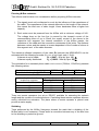
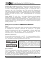
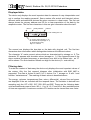
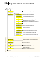
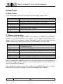
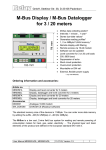
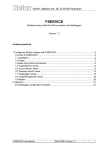
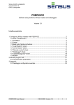
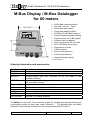
GmbH, Stettiner Str. 38, D-33106 Paderborn
M-Bus Display / M-Bus Datalogger
for 60 meters
166 mm
112 mm
190 mm
PC
Modem
•
•
•
•
•
•
•
•
•
•
•
•
•
M-Bus data collecting station*
Intervals: 1minute .. 1year*
Stores due-date values*
Generates reading profiles*
512KByte FLASH data memory *
Remote display with data filtering
Remote acces via 10-Bit modem
Software can be updated
Level converter for 60 unit loads
300..9600 baud, bit recovery
Suppression of echo
Collision detect
Short circuit protection
•
Overcurrent detection
•
Integrated power supply
* only with MR004DL
Ordering information and accessories:
Article. no.
MR004C
MR04W
MR004FA
MR004DL
Art.no. suffixes
-US
Accessories
KA003
MOD001
SW_DOKOM
Level converter for 60 unit loads in housing for DIN rail
Level converter for 60 unit loads in wall mountable housing
Remote display and level converter for 60 unit loads in wall
mountable housing
Remote display, data logger and level converter for 60 unit loads in
wall mountable housing
Version for mains supply of 110VAC
Power cable (2m) with german plug (Schuko)
Analogue 10-Bit modem
DOKOM CS (reading software)
The M-Bus is a low cost, 2-wire field bus system for reading and remotely powering of
consumption meters for heat, gas, water, electricity … The physical layer and basic
elements of the protocol are defined in the european standard EN 1434-3.
User manual MR004DL/FA
07.03.02, Version 1.2
1
GmbH, Stettiner Str. 38, D-33106 Paderborn
Table of contents:
1 Installation and startup................................................................................................. 3
2 Description of the M-Bus Level Converter ................................................................... 6
3 Description of the M-Bus Display................................................................................. 8
4 Keyboard operation of MR004FA/MR004DL ............................................................... 9
5 Remote control with commands................................................................................. 14
6 Additional functions of the Datalogger ....................................................................... 14
7 PC-Software FService ............................................................................................... 15
8 Addendum ................................................................................................................. 16
Firmware Version : 1.9 and higher
This manual describes the M-Bus Display (MR004FA) and the M-Bus Datalogger
(MR004DL). Both devices can be operated as a transparent level converter and as a
remote display with keyboard or by remote control. The datalogger adds the possibility
to automatically read all the meters in the network and store the data into the internal
FLASH memory.
Standards:
The Level Converter (MR004W), the M-Bus Display (MR004FA) and the M-Bus
Datalogger (MR004DL) follow these standards:
M-Bus:
Emmission:
Immission:
EN1434-3
DIN EN50081-1, EN 55022 class B, EN 60555
DIN EN50082-2, ENV 50140, ENV 50204, EN 61000-4-4
Subject to change without notice. We will not be liable to you for any damages made by use of the
described hardware and software.
© 2002 by Relay GmbH
2
07.03.02, Version 1.2
User manual MR004DL/FA
GmbH, Stettiner Str. 38, D-33106 Paderborn
1 Installation and startup
Drill pattern:
Connectors:
Fuse
Sicherung
Power Slave Max Short
PC
GND TX RX S+ SRS232 (PC) RS485
MODEM
M+ M- M+ M- M+ MM-Bus
N L
RS232:
GND
TX
RX
Ground potential of the interface
Data line for reception (transmit of PC)
Data line for transmission (receive of PC)
RS485:
S+, S-
Terminals for RS-485 interface (observe polarity)
M-Bus:
M+, M-
M-Bus terminals (3 pairs). M-Bus devices are wired polarity
independent in parallel to the same line. The signs +, - mark only
the different bus lines.
Power:
N, L
Earth for symmetry of bus and surge diverting
Terminals for power supply (230V AC or 110VAC for –US version),
polarity independent
User manual MR004DL/FA
07.03.02, Version 1.2
3
GmbH, Stettiner Str. 38, D-33106 Paderborn
LED signals:
Power (green):
Slave (yellow):
Max (yellow):
Short (red):
Power supply is O.K.
M-Bus slave is transmitting
Maximum current exceeded
Over current (short circuit)
RS232 interface:
The M-Bus can be accessed via an RS232C interface. The signals TXD, RXD and GND
(PC notations) are wired to terminals and to both DB9 connectors at the housing. The
upper DB9 socket (female) is designed for a PC and the lower DB9 plug (male) for a
modem. Only one of these three connectors can be used simultaneously. You can
attach a 1:1 serial cable to PC or the modem cable to modem. The modem must be
configured before it is connected (see addendum: “Modem configuration”).
Pinning of DB9 connectors:
Pin
Socket
Plug
Usage socket
Usage plug
2
RXD
TXD
Transmit to PC
Receive from modem
3
TXD
RXD
Receive from PC
Transmit to modem
4
-
DTR
Unused
Always active
5
GND
GND
Ground potential
Ground potential
7
RTS
CTS
Handshake unused
Always active
8
CTS
RTS
Always active
Handshake unused
Pin 1, 6 and 9 are not connected
RS485 interface:
The PW60 normally activates the receive mode on the RS485. On reception of data
from the M-Bus slaves it switches to transmit mode (RS485 transmitter active). About
37ms after the last received data bit (0) the receive mode is re-entered. The RS485
interface of the PW60 is not addressable. There is an internal line termination of 1kΩ
inside the PW60. A stronger line termination of 120Ω can be obtained by connecting a
resistor of 130Ω between the terminals S+ and S-.
Simultaneous use of interfaces:
In case of a local readout using the keyboard of the remote display or during an
automatical readout the RS485 and RS232 interfaces do not have access to the M-Bus.
These functions and the contemporary use of the RS485 and RS232 interfaces can
produce temporary disturbances in communication.
Exchange of the fuse:
Over voltages on the power supply input may cause the fuse to blow. Please switch off
or disconnect the mains power (danger of life) before inserting a new fuse (type 5x20
250V 0,16A slow blow / 5x20 110V 0,25A slow blow for –US version). The fuse is
removed by pulling the fuse holder. You can use a screw driver to open the fuse holder.
4
07.03.02, Version 1.2
User manual MR004DL/FA
GmbH, Stettiner Str. 38, D-33106 Paderborn
Hints for installation:
•
•
•
•
•
•
•
•
Write down the individual ID no. of the meters in the flats / real estates
Configure the meters or puls adaptors
Configure the M-Bus Display / Datalogger (using keyboard or with the service
software FService on a Laptop or via Modem)
Log in with the PasscodeB (predefined to: 00001767)
Setup baud rates, search mode .. in the menu „Display config.“
Start search for installed meters with „List of slaves - AutomaticSearch“
Check the list of slaves for missing meters, you can evtl. add slaves manually
Change the predefined passcodes (at least passcode B)
Trouble shooting:
•
No LED is on:
Check power supply and fuse.
•
Red LED is on:
Check the M-Bus wiring for short circuits and ground loops. Defective slaves can
also produce an overcurrent. The source for the short circuit can be found easier by
removing some bus segments from the M-Bus terminals.
•
Yellow LED (Max) is staticly on:
The bus current has exceeded the nominally allowed current. Check the number of
connected meters. You can connect 60 meters specified with 1 unit load (1.5mA),
but only 30 meters specified with 2 unit loads (3mA). Are there defective slaves or
open cable ends lying in the earth of building-plots?
•
One or more meters are not detected in automatic search procedure:
Retry automatic search. Check baud rate and address of this meter. You can add
the meter manually to the list of slaves and perform then a single readout of this
meter.
•
No reply from meter:
Check baudrate and address of this meter. Check the bus extension: The bus
voltage at any slave must be >24V. Temporarily remove other bus segment.
•
„Status: Error“:
MR004DL/FA in waiting status (inactive): Press ↓ and C keys simultaneously to view
the list of errors. Please note the error codes and then delete the error codes by
pressing the → key. The most important error codes can be decoded using the table
in the addendum.
•
Wrong Passcode
Please do the following steps, if you have forgotten the passcode:
Do the actions which are described in “Status: Error” and then press the → key
again. Please write down the 16 digit string (display config) and send it together with
the firmware version no. and serial no. by email to [email protected]. We will send
you a working passcode.
User manual MR004DL/FA
07.03.02, Version 1.2
5
GmbH, Stettiner Str. 38, D-33106 Paderborn
2 Description of the M-Bus Level Converter
Functionality:
The RS232C and RS485 interface signals are directly connected to the M-Bus all the
time besides during the operation via keyboard, the remote access using the command
menu and the automatic readout. External connected controllers (laptop, building
control systems ..) can use the device during the inactivity as a level converter for the
physical layer of the M-Bus. The software of the controller must provide the
communication protocols of the connected meters. The members of the W60 family are
able to supply up to 60 slaves (unit loads) with power.
Technical data
Supply:
Voltage:
230VAC, 50Hz, 25W respective
110VAC, 50Hz, 25W (-US version)
Environment:
Operating temperature:
Storage temperature:
Humidity:
0..+45°C
-10..+60°C
10..70% (non condensing)
Housing:
Dimensions:
Protective class:
Material / colour:
W x H x L = 166 x 190 x 112 (mm)
IP53 (cable glands must be closed)
PS / light-grey (similar to RAL 7035)
Weight:
1,3kg
M-Bus specifications
Parameter
min.
Max. no. of unit loads (slaves)
typ.
unit
15
Ω
60
Internal resistance
Bus voltage mark = log. 1 (@ 0mA)
max.
38,5
39,0
39,5
V
Voltage drop for space = log. 0
12
12,5
13
V
Warning current level (Max LED)
90
100
110
mA
Level for over current interruption (Short LED)
130
140
160
mA
Level for bit detection from slave
7
mA
Level for collision detect
30
mA
1 unit load = 1.5mA
The device transmits a break signal (space) for minimum 50ms after a collision and for
minimum 100ms after a short circuit.
6
07.03.02, Version 1.2
User manual MR004DL/FA
GmbH, Stettiner Str. 38, D-33106 Paderborn
Planning M-Bus networks:
Two effects must be taken into consideration before projecting M-Bus networks:
1. The signals must not be distorted to much by the influence of the capacitance of
the cable. The capacitance of the network depends on the length of the network,
this means the total sum of cable length. Lower baudrates allow a higher bus
capacity.
2. Each meter must be powered from the M-Bus with a minimum voltage of 24V.
The voltage drop on the bus line is caused by the transmit current of the
communicating slave of up to 20mA, the supply current of the slaves in the
respective bus segment, the internal resistance of the M-Bus master, the
resistance of the cable and the connection resistances of the joints. The distance
between a slave and the master is inverse dependent of the number of slaves in
this segment and of the cable diameter.
The maximum allowed resistance of the cable RL between the MR004DL/FA can be
estimated with the following formulas (N = no. of unit load, each 1.5mA):
N slaves at end of cable:
RL = (9467 - 15 x n) / (n + 14) Ω
N slaves equally distributed:
RL = (18933 - 30 x n) / (n + 28) Ω
The calculation for a standard phone cable JYSTY nx2x0.8 (75Ω/km, 150nF/km) presents
the following values:
Baudrate
Max. total cable length (@150nF/km):
No. of unit loads in the
respective segment
1
10
30
60
9600 Baud
1 km
2400 Baud
4 km
300 Baud
12 km
Max. distance to the meter (@75Ω/km)
Equally distributed slaves at end of cable
8,4 km
8,4 km
6,5 km
5,2 km
4,1 km
2,7 km
2,6 km
1,5 km
There are remote repeaters (our art.no. DR007) available for extending the network
length and the number of connected slaves. Cascading these remote repeaters allows a
nearly unlimited bus extension. The place where a remote repeater is placed must
provide a mains supply.
Shielding
Tests performed by the M-Bus Usergroup showed the result that a shielding of the
M-Bus cable is not necessary. Please avoid a connection between any of the bus lines
to the shielding or protective ground.
User manual MR004DL/FA
07.03.02, Version 1.2
7
GmbH, Stettiner Str. 38, D-33106 Paderborn
3 Description of the M-Bus Display
Functionality
The M-Bus Display allows reading the meters using the keyboard and viewing the
consumption values on the LCD. The reading personell is then able to get the data of
many meters from one central location without the need to enter all the flats and without
further technical equipment (laptop..). Additionally the device offers a so-called
command mode for remote readout of meters using a standard modem (10-bit). The MBus software Dokom CS and FService support this command mode.
Installation
After login with a passcode (predefined as 00001767) the operator gets access to the
menu system, which is described later. It is important to generate the list of meters for
readout of data. The automatical search for installed meters will be much faster, if the
user reduces the search options in search mode or search baudrates (e.g. searching
with 300 baud is very slow). These options can be selected in the menu „Display
config.“ You should also change passcode B to prevent other persons from changing
the setup and passcodes.
Error messages
An exceed of the maximum allowed current and short circuit are signalled with LEDs
under the terminal lid compartment and also on the LCD. If there are problems with
interpretation of the M-Bus data the display shows „Status: Error“. The “list of errors“ is
shown on the LCD after simultaneously pressing the ↓ and C keys in the inactive state.
Please note the error codes and then delete the error codes by pressing the → key. The
most important error codes can be decoded using the table in the addendum. On restart
after power fail the error list is also deleted.
Passcode protection
The M-Bus Display distinguishes between 3 passcode modes and 2 passcode levels:
The operator is requested to enter a passcode after pressing any key in the standard
mode (mode A). In this mode the passcode A (reader´s passcode) gives only low level
access limited to readout functions. The caretaker or tenant can read single meters by
selection from the list of slaves or all meters from the network. It is not possible to
change the list of slaves or other options of the M-Bus Display here.
The login with the passcode B instead of passcode A gives access to the complete
menu. On delivery the predefined value for passcode A is 00000000 and for passcode
B is 00001767. This allows a simple login to level A by just pressing the E-key. We
strongly recommend to change passcode B to avoid manipulation by unauthorized
persons. You can setup the passcode from the menus „Display config. – New passcode
A” and “Display config. – New passcode B”.
8
07.03.02, Version 1.2
User manual MR004DL/FA
GmbH, Stettiner Str. 38, D-33106 Paderborn
Access by ID: The M-Bus Display support a different setup of the passcode mode from
the menu „Display config. – Passcode mode“. If this mode is activated, the user (tenant)
can make a readout limited to his own meter(s). After first key-press the tenant is
requested to type in the ID (identification no.) of the required slave. Afterwards this
single meter is read and its data displayed. Please note that only meters which support
secondary addressing are readable in this mode. The access to the menu is additionally
possible in this mode after input of the ID 00000000 and login with the described
passcodes.
Access by Adr: This mode allows a direct readout of meters using their primary
addresses without any login procedure. This mode is similar to “Access by ID”. The
primary address for global readout 254 is used by default. So by just pressing the E key
you can read a meter if it’s there is only one meter connected. The cursor keys allow
editing the address. You can leave the input mask and step to the passcode request by
pressing 3-times the → key .
4 Keyboard operation of MR004FA/MR004DL
Basics:
Besides the control using Fservice the device includes 4 keys and a backlighted display
for comfortable, local access to all functions. The buttons give a very precise,
mechanical feedback and each input is acknowledged by an acoustic signal (beep).
Execution of menu entries and input of numbers are described later. The device
automatically returns to inactive state after some minutes with no input.
Selection of a menu entry:
An arrow marks the active menu entry on the LCD. The arrow is moved down with the ↓
key and up with the → key. Pressing the E button executes the current, selected menu
entry. The C button cancels the input and exits from the menu.
↓ key
After input of passcode and confirming with the E key the main
menu is activated. You can see always two entries of this
menu. The first displayed lines are “Readout of all” and “Single
readout”. By pushing the ↓ button the LCD scrolls to the next
part of the menu. In this example the line “Single readout” will
then be marked with the arrow. This submenu would be entered
with the E key.
Input of numbers:
The ↓ button increments the number of the active position by one. After the 0 ist restarts
with the 9 again. The → key moves the cursor to the next position on the right. The
active position is blinking. After pressing → at the most right digit the cursor moves to
the most left digit. The E button ends and acknowledges the input regardless of the
current position. You can cancel the input with the C key.
User manual MR004DL/FA
07.03.02, Version 1.2
9
GmbH, Stettiner Str. 38, D-33106 Paderborn
Displayed data:
The device only displays the most important data for reasons of easy interpretation and
not to confuse the reading personell. Some meters offer actual and historical values,
different tariffs and additional devices like pulse counters in a heat meter. The first row
always shows the primary address and ID for a clear association of the data to the
respective meter. The first two characters in this row give information about the tariff.
tariff no.
primary address
meter ID
counter reading with unit
A: current value (storage no. 0)
B: due-date value (storage no. 1)
E: value with error flag
digit: no. of device
The second row displays the due-date or the data with physical unit. The first two
characters show information which distinguishes between the different values:
The character “A” marks current values which are characterized by storage no. 0. The
character “B” appears with due-date values (storage no. 1). If the respond frame of the
slave contains activated temporary or permanent error bist in the Status byte , an “E”
will be shown. The first character follows one digit for the device (0 = main device).
Filtering data:
To make the readout of data easy the device only displays the most important values of
the meters. Only the first respond telegram after initialization with SND_NKE is
supported. The data is limited to tariff 0 to 3, device 0 to 7, storage no. 0 and 1 and
function “instantaneous”. The marking of these values is described above.
The energy, volumes, temperatures (flow, return, differential), volume flow and power
are displayed if the are included with the respond frame. The limitation is derived from
accepting only the VIF´s $00 ..$1F, $58..$63 and $6E. These are the following basic
units and additional power of tens: Wh, J, l, kg, W, l/h °C and HCA. Also available points
of time are supported. A maximum number of 30 entries can be viewed from one meter.
10
07.03.02, Version 1.2
User manual MR004DL/FA
GmbH, Stettiner Str. 38, D-33106 Paderborn
Menu structure:
Status report:
OK:
overload:
max.load:
error:
MB Display V1.9
Status: OK
Device ready for work
Nominal bus current exceeded
Bus off while over current
Error occured in data interpretation
Passcode B allows access to all functions
Passcode A allows access limited to these functions:
Passcode request *
* The tenant has no access to the menus in the modes "Access via
ID" / "Access via Adr". He is requested to input a meter ID / Adr
instead of a passcode.
Readout of all
Single readout
List of slaves
The meter data of all devices are read and displayed
on the LCD based on the list of slaves.
After selecting a meter from the list of slaves this slave
will be read and the consumption values will be displayed.
Show/edit list
AutomaticSearch
Add slave
Remove slaves
Sort slave list
Shows the list of slaves. Allows editing of:
Primary address, ID and baudrate
Automatic generation of the list of slaves by a search
for ID / primary address with several baudrates
Append a meter to the list of slaves
Remove a meter from the list of slaves
Selectable option for sorting the list of slaves:
primary address, ID, no sorting
Page 2
Page 2
User manual MR004DL/FA
07.03.02, Version 1.2
11
GmbH, Stettiner Str. 38, D-33106 Paderborn
Page 1
Page 1
ID of location
Shows the ID of location (description)
Display config.
Highest baudr.
Highest baudrate for automatic search
Lowest baudrate
Lowest baudrate for automatic search
Search mode
Selects search mode: Adr+ID,only Adr, only ID
Passcode mode
Selects passcode mode:
Standard: requests passcode on startup
Access by ID/Adr: requests ID/address for single read
New passcode A
Change of passcode A (reader)
New passcode B
Change of passcode B (global access)
Modem mode
Setup of modem mode
Testfunctions
Testfunctions for production (passcode protected)
SND_NKE mode
Activate / deactivate initialize with SND_NKE
MWh_cbm mode
Activate / deacivate preferred display in MWh / cbm
These menus are only available with MR00xDL:
Clock&Calendar
Data collector
12
Display and edit date + time. Press E-key for editing.
Format: DD.MM.YYYY
Setting up readout interval and start time.
Format: DD.MM.YYYY
Read and store
Manually starts a readout and storage of all meters
according to the list of slaves
Data exchange
Display of stored data:
First select a timepoint from the list. Then all data of
this point of time are shown on the LCD.
07.03.02, Version 1.2
User manual MR004DL/FA
GmbH, Stettiner Str. 38, D-33106 Paderborn
Description of the most important menus
Readout of all:
This entry reads all meters according to the list of slaves and displays their data. For
each meter its baud rate and primary or secondary address is used for communication.
Single readout:
The readout of single meters also uses information from the list of slaves. The submenu
shows the list with the information of position, primary address and ID. The meter will be
read after moving the cursor to the desired position and pressing the E button.
Automatical generation of the list of slaves:
The automatical search for installed meters with generation of the list of slaves is
started from the menu entry “List of slaves – AutomaticSearch” with the E key. The C
button cancels the current part of search and jumps to the next search step. Especially
searching with 300 baud takes much time. You should select just the needed baudrates
from the menu “Display config. – Highest baudrate / Lowest baudrate” to avoid
unnecessary long search times. It is also possible to limit the serch to primary or
secondary addressing using the menu “Display config. – Search mode”. At the end or
the search the display shows the number of detected meters. You should check the
entries of the list of slaves from the menu “List of slaves- Show/edit list”.
Editing the list of slaves:
The entries in the list of slaves can also be edited by the user using the menu “List of
slaves – Show/edit list”. Move the cursor to the desired position and start the edit mode
with the E key. You can change the chars with the ↓ button and step to the next position
with the → button. The E key confirms and the C key cancels editing. The changes
affect only the list of slaves, but not the meter options itself. Editing entries is useful if a
meter has been exchanged. It is also possible to add new meters from the meu “List of
slaves – Add slave” or to delete single meters from the submenu “– Remove slaves”.
Setting up baud rates:
On delivery the M-Bus Display / Datalogger is confiured to search with all supported
baudrates: 300, 2400 and 9600 bd. You can accelerate the search procedure by limiting
the search baudrates with “Display config. – Highest baudrate” and “ Lowest baudrate” .
Implemented elements of protocol and data types
The device includes no meter-specific interpretation, but accepts all meters with a MBus telegram according to the documentation of the M-Bus Usergroup and the
European standard EN1434-3, which fulfill the following demands:
• Variable data structure (mode 1) or fixed data structure (mode 1 or mode 2)
• Number formats: Integer (8bit, 16bit, 24bit, 32bit, 48bit, 64bit)
Real (32bit)
BCD (2digit, 4 digit, 6digit, 8digit, 12 digit, 16digit)
User manual MR004DL/FA
07.03.02, Version 1.2
13
GmbH, Stettiner Str. 38, D-33106 Paderborn
5 Remote control with commands
Function
In the inactive state the MR004FA and MR004DL work like simple level converter. The
signals of the RS232C and RS485 interfaces are converted to M-Bus signals and vice
versa. The CPU watches the data transmission and reacts on certain control frames.
Following a successful login command the device switches itself from level converter
mode to command mode. Then the device can be controlled using the RS232C
interface directly with a PC or via modem. This command mode includes reading single
meters, downloading alll stored data, configuration and even an update of the software.
The document “W60CMxxE.DOC” (xx = version) describes all commands for
development of adapted readout software. The following documentation describes our
software Fservice for configuration and remote control of MR004DL and MR004FA.
Operation with modem
The M-Bus protocol uses an 11-bit format with very critical timing requirements. The
modems which are nowadays available on the market don´t support this format.
Therefore we offer a special solution called “M-Bus modem” for use with any level
converter and also with MR004DL/FA in level converter mode.
In spite of this the command mode makes use of standard modems with 10-bit format.
There are two programs which support communication to MR004DL/FA using
commands: FService and Dokom CS (under preparation).
6 Additional functions of the Datalogger
Functionality
The Datalogger MR004DL software offers a scheduler for time-triggered readout and
storage of M-Bus data. The scheduler distinguishes between two modes:
a) Readout in fixed periods from one minute to one week
b) Readout at fixed points of time (e.g. at end of each month)
On automatic readout the Datalogger reads all meters which are included in the list of
slaves. The first respond telegram after a SND_NKE + REQ_UD2 is stored together
with the readout time into the FLASH memory.
Selecting readout time
The readout time can be selected using the keyboard and LCD or by remote access
with a PC or via a modem. The following selections are possible via keyboard:
• 1, 2, 3 , 5, 10, 15, 20, 30 minutes interval
• 1, 2, 3, 4, 6, 12 hours interval
• once per day, once per week, twice per week, once per month
• 4 times per year, 2 times per year and once per year
• 0 times per year = logging function deactivated
14
07.03.02, Version 1.2
User manual MR004DL/FA
GmbH, Stettiner Str. 38, D-33106 Paderborn
Calculation of storage capacity
The size of the data memory is 512Kbyte. Versions with 1 MByte, 2MByte or 4Mbyte
are under prparation. Worst case the M-Bus frame can be 261 bytes long, but mostly
the telegrams are much shorter. A typical heat meter for example transmits 79 bytes.
Water meters and pulse adaptors often use even shorter frames. A length field and a
point of time is additionally stored with the M-Bus frame. This adds 12 Bytes. In our
example 60 heat meters with 79 bytes M-Bus frame + 12 bytes occupy 5462 bytes
inside the FLASH for every readout. The FLASH is organized as a ring memory with 8
blocks of 64kB (65536 bytes) or in total 512kB. If the current block is full, the next block
will be erased completely. So it could happen that only 7 block are full with data. In this
example there is enough memory to store minimum 7 x 65536 / 5462 = 83 readouts.The
practice shows that usualy there are often installations with less meters and shorter MBus telegrams.
Download of stored data
The contents of the data memory can be downloaded in command mode using a direct
or a modem connection with FService or Dokom CS.
The most current readouts are also available via keyboard and LCD. The menu “Data
exchange” shows a list with the last 25 readout times. You can scroll through the
different points of time and select one with the E button. Then the data of all meters for
this readout is displayed in the same manner as with “Readout of all”.
7 PC-Software FService
The devices can be operated via keyboard without software or as simple level
converters with any M-Bus software. The software FService offers a comfortable access
to and control of the Datalogger and M-Bus Display. The software can work locally with
a PC or remotely via a modem.
The software is described in a special document delivered with Fservice.
User manual MR004DL/FA
07.03.02, Version 1.2
15
GmbH, Stettiner Str. 38, D-33106 Paderborn
8 Addendum
8.1 Error Codes
The following table shows the error codes. See “Error fixing – Status: Error”:
Code
$00
$01
$11
$18, $19, $1C
$20
$30, $31, $32, $33
$51,$52
$61, $62
Error
No error
RAM error (please send the device to us for repair)
EEPROM write problem
EEPROM read problem
Problem with communication to real time clock
Problem with FLASH memory
Problem with data in real time clock
Problem with YModem transmit , Xmodem reception
8.1 Modem Configuration
You must configure the modem before it is connected to MR004FA or MR004DL.
Please use a terminal software of your choice, e.g. the Windows HyperTerminal and
connect the PC to the modem. Choose 9600 baud, 8 data bits, no parity and one
stopbit. Then input the following commands, each activated by the “Enter” key:
Command
AT
AT&F
AT&D3
ATS0=1
AT\Q0 or AT&K0
AT\J0
AT&W0
AT&W1
Function
for baudrate detection
load factory settings
resets modem after DTR signal off
modem answers a call after one ring
deactivate hardware and software handshake
no adaption of the serial baudrate to line speed
stores the settings into profile 0
stores the settings into profile 1
These commands are examples, which will work with several, but not all modems on
the market. Please study the manual of your individual modem to find out whether you
need to use modified commands.
After configuration please connect the modem to the MR004FA/DL using the cable
delivered with the modem and plug it into the DSUB labelled with “MODEM”.
16
07.03.02, Version 1.2
User manual MR004DL/FA