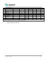
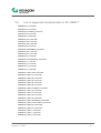
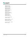
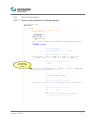
1
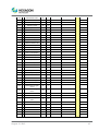
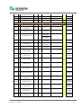
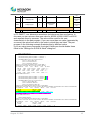
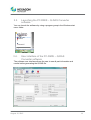
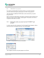
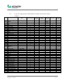
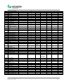
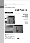
USER AND INSTALLATION MANUAL PC-DMIS – Q-DAS Converter Version 4.xxxx.y49 Hexagon Metrology GmbH Siegmund-Hiepe-Str. 2-12 35578 Wetzlar, Germany 12. August 2015 Table of Contents 1. General information .......................................................................................... 3 1.1. Software objectives .................................................................................. 3 1.2. Software requirements ............................................................................. 3 1.3. Software warranty and support ................................................................ 3 1.4. PC-DMIS comparison with PC-DMIS – Q-DAS Converter – Compatibility table 4 1.5. 2. 3. Other information ..................................................................................... 4 Installation instructions .................................................................................... 6 2.1. Scope of supply ....................................................................................... 6 2.2. Installation ................................................................................................ 6 2.3. Uninstalling the software .......................................................................... 7 How to use the software ................................................................................... 8 3.1. Language setting...................................................................................... 8 3.2. Creating the measurement program in PC-DMIS™ ................................. 8 3.3. Launching the PC-DMIS – Q-DAS Converter software .......................... 14 3.4. User interface of the PC-DMIS – Q-DAS Converter software ................ 14 3.5. Configuration of the converter ................................................................ 15 3.6. ONLINE Conversion............................................................................... 29 3.7. List of supported Q-DAS® K-fields and their data origin ........................ 32 3.8. List of supported characteristics in PC-DMIS™...................................... 35 3.9. Some Examples ..................................................................................... 37 Note: In spite of all our efforts, we cannot guarantee that the documentation is completely free of errors. We welcome any constructive comments and suggestions. We would like to express our special thanks to Q-DAS for the close co-operation during the development of this converter. We would also like to thank all of our customers who provided us with strong support with tests and suggestions during development. Q-DAS Gesellschaft für Datenverarbeitung und Systemtechnik mbH Eisleber Straße 2 D-69469 Weinheim Germany August 12, 2015 2 1. General information 1.1. Software objectives This software has been specially designed to allow generation of Q-DAS ASCII data under the software PC-DMIS software package, Version 2012. This converter allows manual conversion (OFFLINE) or automatic conversion (ONLINE) of the measurements results. It can be started by an external command from the measurement program during its execution. 1.2. Software requirements The software has been developed for the Windows 7 operating system. No software tests have been conducted with other operating systems. If you are using Windows XP and you have installed this software, we assume no warranty for the full functionality of the software. The tests of compatibility of the data generated with qs-STAT were conducted with version qs-STAT Millennium. However, in accordance with Q-DAS®, the format may also be used for older versions. The relevant PC-DMIS version must be installed on the same computer in order to be able to use the converter. 1.3. Software warranty and support Please refer to the current license.txt file for further information in the installation folder of the software. This will be displayed during installation and must be accepted. Any contrary agreements must be defined in writing and can only be entered into with the software manufacturer. Agreements with intermediaries are invalid. August 12, 2015 3 1.4. 1.5. PC-DMIS comparison with PC-DMIS – Q-DAS Converter – Compatibility table PC-DMIS Version PC-DMIS – Q-DAS Converter Version 2010 MR3 4.2010.3xx 2011 4.2011.0xx 2011 MR1 4.2012.1xx 2012 4.2012.0xx 2012 MR1 4.2012.1xx 2013 4.2013.0xx 2013 MR1 4.2013.1xx 2014 4.2014.0xx 2014.1 4.2014.1xx 2015.0 4.2015.01xx Other information The offered license refers to information associated with the computer hardware and can only be transferred once per calendar year to another computer. We therefore recommend that the license request is sent from the computer that will actually be used with the converter. You will need a new license file if you are planning to upgrade (which will result in a change of the main software version). No new license is required in case of minor revisions. Software maintenance will be subject to a software maintenance contract entered into in conjunction with the PC-DMIS license. August 12, 2015 4 Please observe the terms and conditions of the license agreement that appears during the installation. August 12, 2015 5 2. Installation instructions 2.1. Scope of supply The software is available for download on the ftp Server of Hexagon Metrology GmbH at: http://ftp.hexmet.de/PC-DMIS/PC-DMIS_Q-DAS_Converter 2.2. Installation Please perform the following steps to download the software on your PC-DMIS computer: • Verify the PC-DMIS version you are currently using on this computer. • Unpack the WinZip archive on your PC-DMIS computer. • Start the “Setup.exe” file to install the software. Please follow the instructions of the setup process carefully. • Start PC-DMIS and open any measurement program you want. • Start PC-DMIS – Q-DAS Converter by using the Windows start group associated with it. Converter will automatically check if a license file exists. If not, the following dialog with a license request will appear: • You can select the user interface language by using the “Language/Sprache” menu option. Enter the company name and production site. You will have the choice between a demo license and a purchased (unlimited) license. Simply check mark the required license type. • After selecting a purchased license a field with your order number will appear. Please enter the PC-DMIS portlock number here. After having done this you can save your license request with the <Create file> button. August 12, 2015 6 • You must enter the portlock number of the PC-DMIS Portlock into the “PC-DMIS Portlock No. (TAG)” field. You can find this number as a sticker on the portlock. It can also be recalled under the PC-DMIS Help About PC-DMIS... menu option. • Now send your license request to [email protected] • Within 24 hours, a license file will be sent to the email address from which the request was sent. • Upon receipt, copy this license file into the directory where converter is installed. • Now the software is ready for use. • Should you have any technical questions please contact our PC-DMIS Hotline under the phone number: +49 6441 -207 -207 2.3. Uninstalling the software Use the appropriate routine in the program folder to uninstall the software. August 12, 2015 7 3. How to use the software 3.1. Language setting The software is available in the following languages: • • • • English French Czech Portuguese • • • • German Italian Spanish Hungarian Please contact your supplier if you need a different language. The language can be selected using the File – Language menu option. Also the axes names are defined in conjunction with the language setting (applies to axes names that are compatible with version 1). 3.2. Creating the measurement program in PC-DMIS™ • Create your measurement as usual through the PC-DMIS Software. Please note the following if you are creating dimensions for evaluation: The output option must be set to “STATS” or “BOTH”. Only then will converter include dimensions in the statistical evaluation. • If a dimension is not marked while the data is imported into the converter, it will be characterized by the attribute 255 or 256 in the Q-DAS file. This means that the dimension will not be included for statistical evaluation. • Depending on the start up option of the converter (/i or /a) the export will start automatically or must be confirmed again in the main converter window. For further information please refer to chapter 3.7 of this manual. This is most important if you wish to add events (K-fields) to dimensions. K-fields can be prompted through trace field commands in PC-DMIS. Trace fields are added in PC-DMIS with the Statistics command Trace field option. Paste The K-field to be prompted is entered into the Name field. As default, “No Display” is set in the options. There are several ways to fill the created trace field with content now. Use a comment to recall settings. An input command is used to pass them to the trace field. Another option is to use assignments. August 12, 2015 8 • Trace fields are supported for the following K-fields. DFD Key /0 Field name Length Type Catalog based Customer description Remark DFX Value / Additional data K0005 /0 Events 255 A K0006 Batch number 14 A K0007 Cavity number 5 I X K0008 Inspector name 5 I X K0009 Text 255 A K0010 Machine number 5 I X K0012 Gage number 5 I X K0014 Part ID 40 A K0015 Purpose of the inspection 5 I K0016 Production code 30 A K0017 Tool number 30 A K0053 Order 20 A K0054 30 A K0055 30 A K0056 30 A K0057 30 A K0058 30 A K0059 30 A K0060 30 A K0061 10 I X K0062 10 I X K0063 10 I X “#” must precede value Defined field contents DFX Part data K1001 Part number 30 A K1002 Part description 80 A K1003 Part descvription short 20 A K1004 Part update status 20 A K1005 Product 40 A K1007 Part number Abbreviation 20 A K1008 Part type 20 A K1009 Part code 20 A K1014 Part ID 20 A K1021 Manufacturer number 20 A DFD August 12, 2015 9 K1022 Manufacturer name 80 A K1031 Material number 20 A K1032 Material description 40 A K1041 Drawing number 30 A K1042 Drawing Amendment 20 A K1052 Contractor name 40 A K1053 Order 40 A K1061 Client Number Text 20 A K1062 Client Description 40 A K1072 Supplier Description 40 A K1081 Machine Number Text 24 A K1082 Machine Description 40 A K1083 Machine number 10 I K1085 Machine location 40 A K1086 Work Cycle Operation 40 A K1087 Operation Description 40 A K1100 Plant Sector 40 A K1101 Department 40 A K1102 Workshop 40 A K1103 Cost centre 40 A K1104 Shift 20 A K1201 Test facility Number Text 24 A K1202 Test Facility Description 40 A K1203 Reason for test 80 A K1206 Test location 40 A K1210 Measurement type 5 I K1222 Inspector name 40 A K1231 Measurement program number 20 A K1232 Measurement program version 20 A K1302 Test batch 40 A K1303 Plant name 40 A K1343 Test Plan Development Date 20 D K1344 Test Plan Developer 40 A K1802 User field content 1 255 A K1812 User field content 2 255 A K1822 User field content 3 255 A K1832 User field content 4 255 A K1842 User field content 5 255 A August 12, 2015 10 K1852 User field content 6 255 A K1860 User field description 7 50 A K1862 User field content 7 255 A K1900 Remark 255 A Dimensional data K2001 Characteristic Number 20 A K2003 Characteristic Abbreviation 20 A K2004 Characteristic type 1 I Defined field contents Modules AS/PC/PV K2005 X Characteristic class 1 I Defined field contents K2006 X Control item 1 I Defined field contents K2007 X Control Type 1 I Defined field contents K2015 X Tool wear type (Trend) 1 I Defined field contents K2093 Processing status 80 A Only for all characterist ics K2095 Element Code 40 A Only for all characterist ics K2096 Element Index 20 A K2097 Element Text 50 A K2203 Car body mode 1 I K2216 Master Serial Number 20 A Only for all characterist ics K2311 Production Type Text (Operation) 20 A Only for all characterist ics K2320 Contract number 20 A Only for all characterist ics K2401 Gage number 40 A Only for all characterist ics K2402 Gage description 80 A Only for all characterist ics Process capability establishment 1 I K2434 X August 12, 2015 DFD Only for all characterist ics Only for all characterist ics 0=off 1=on Yes=1 / No=0 Only for all characterist ics Only for all characterist 11 ics K8500 Subgroup size 5 I K8501 Subgroup type 3 I Only for all characterist ics Defined Field contents Only for all characterist ics Additional Trace fields FileName String for file name 255 A In PC-DMIS™, one dimension sometimes includes more than one feature. In this case you can set more than one value for K2005, K2006, K2007 or K2015 and separate them by commas. The value will be used for the next characteristic in the part program. If you use more than one value (separated by a comma) the values are used in the order in which they are listed. The part program in the following example illustrates this by different colors. If you are using trace commands for single K-fields you should disable these fields in the “Settings for Q-DAS K-fields” dialog box. DISPLAYPRECISION/3 TRACEFIELD/NO_DISPLAY,LIMIT=1 ; K2005/0 : 3 TRACEFIELD/NO_DISPLAY,LIMIT=1 ; K2006/0 : 1 COMMENT/REPT,LOC1 / X-Axis for Hole 204 ,LOC1 / Y-Axis for Hole 204 ,LOC1 / Z-Axis for Hole 204 ,LOC1 / Diameter for Hole 204 DIM LOC1= LOCATION OF CIRCLE CIR1 UNITS=MM ,$ GRAPH=OFF TEXT=OFF MULT=10.00 OUTPUT=BOTH AX NOMINAL +TOL -TOL MEAS DEV OUTTOL X 203.199 0.000 0.000 203.199 0.000 0.000 ----#---Y 76.200 0.000 0.000 76.200 0.000 0.000 ----#---Z 0.000 0.000 0.000 0.000 0.000 0.000 ----#---D 25.400 0.000 0.000 25.400 0.000 0.000 ----#---END OF DIMENSION LOC1 TRACEFIELD/NO_DISPLAY,LIMIT=15 ; K2005 : 2,2,2,2 TRACEFIELD/NO_DISPLAY,LIMIT=15 ; K2006 : 0,0,1,1 TRACEFIELD/NO_DISPLAY,LIMIT=15 ; K2007: 0,0,1,1 COMMENT/REPT,LOC2 / X-Axis for Hole 204 ,LOC2 / Y-Axis for Hole 204 ,LOC2 / Diameter for Hole 204 ,LOC2 / True Position for Hole 204 DIM LOC2= TRUE POSITION OF CIRCLE CIR1 UNITS=MM ,$ GRAPH=OFF TEXT=OFF MULT=10.00 OUTPUT=BOTH DEV PERPEN CENTERLINE=OFF DISPLAY=DIAMETER AX NOMINAL +TOL -TOL BONUS MEAS DEV OUTTOL X 203.199 203.199 0.000 Y 76.200 76.200 0.000 DF 25.400 0.000 0.000 0.000 25.400 0.000 0.000 ----#---TP MMC 0.000 0.000 0.000 0.000 ----#---END OF DIMENSION LOC2 DISPLAYPRECISION/4 DIM LOC3= TRUE POSITION OF CIRCLE CIR1 UNITS=MM ,$ GRAPH=OFF TEXT=OFF MULT=10.00 OUTPUT=BOTH DEV PERPEN CENTERLINE=OFF DISPLAY=DIAMETER AX NOMINAL +TOL -TOL BONUS MEAS DEV OUTTOL X 203.1990 203.1991 0.0001 Y 76.2000 76.2000 0.0000 DF 25.4000 0.0000 0.0000 0.0000 25.4001 0.0001 0.0001 ------ August 12, 2015 12 TP MMC 0.0000 END OF DIMENSION LOC3 0.0000 0.0002 0.0002 ------ You can insert a comment (report type) at the start of each dimension. This comment is then saved in the Q-DAS® key field K2900. It cannot be changed during the program runtime. August 12, 2015 13 3.3. Launching the PC-DMIS – Q-DAS Converter software You can launch the software by using a program group in the Windows start menu folder. 3.4. User interface of the PC-DMIS – Q-DAS Converter software The software user interface allows the user to see all part information and results before generating the Q-DAS file. August 12, 2015 14 3.5. Configuration of the converter In order to configure the converter for the relevant environmental conditions and requirements of the application, all settings in the “Setup” menu must be checked carefully. 3.5.1. Setup In this dialog you can choose the directory to which your Q-DAS® files are to be saved. The following options are available: File path for Q-DAS ASCII files • Save files in the PC-DMIS™ part program folder By check marking this option the software will save the Q-DAS® files in the same folder as the PC-DMIS™ part program. August 12, 2015 15 • Select an individual folder This option allows the selection of an individual folder during each part program execution. The operator will then be prompted in the main converter window to select a folder. • Save files in the default folder By check marking this option, the directory selected here as default folder will be used for all Q-DAS® files. • It is also possible to define a specific folder in the respective PC-DMIS™ part program. Please refer to chapter 3.8 for further details. • You can create a backup copy of the ASCII file on your local computer by check marking the “Create backup file in directory {Application}\TempData\Save” option. This is done once a file copy has been saved in the destination directory. Q-DAS ASCII File Name You can define the file name convention to be used for Q-DAS ASCII files in the “Q-DAS ASCII File Name” section. Part Name, Revision Number and Serial Number are the values which are available in the header of the part program. The string from the trace field Trace’FileName’ is read in from the part program. Date and time are based on the system time during the file conversion. The selected separator will be inserted between each of the selected values. If you don’t want to use date and time, you will have to use the 4 digits counter. If you fail to do so, the software may overwrite the old files. August 12, 2015 16 The “GM file name rules” option uses the following file name format: {string from Trace Field “FileName”}_MMDDhhmmss DD: Day MM: Month hh: Hour mm: Minute ss: Second Program Settings Use the “Program Settings” section to configure the software in the best way for your application. • Multi-line comments Comments can be used to add explanations for each dimension (socalled “characteristics” in Q-DAS). Each comment is associated to a specific dimension. Some rules must be observed in the PC-DMIS™ program to achieve this effect. Whether a comment is taken into account or not by converter depends on the type of comment and its position in the part program. The comment must be of the report type. The comment must directly precede the dimension. Multi-line comments may contain up to 20 lines. If more than 20 lines are used, they will be ignored. Depending on the status of the “Multi-line comments” checkbox, multi-line comments will be interpreted differently. August 12, 2015 17 Please see the following two examples for a more detailed explanation: Example 1: COMMENT/REPT,Comment for X-Axis ,Comment for Y-Axis ,Comment for Z-Axis ,Comment for D-Axis MOVE/CLEARPLANE DIM 1= LOCATION OF CIRCLE KREIS1 UNITS=IN ,$ GRAPH=OFF TEXT=OFF MULT=10.00 OUTPUT=BOTH AX NOMINAL +TOL -TOL MEAS MAX MIN DEV This comment will not be used, because the MOVE/CLEARPLANE command was placed between the comment and the dimension. Example 2: COMMENT/REPT,Comment for X-Axis ,Comment for Y-Axis ,Comment for Z-Axis ,Comment for the D-Axis DIM 1= LOCATION OF CIRCLE KREIS1 UNITS=IN ,$ GRAPH=OFF TEXT=OFF MULT=10.00 OUTPUT=BOTH AX NOMINAL +TOL -TOL MEAS MAX MIN DEV This comment will be used, because there is no command between the comment and the dimension. Note: August 12, 2015 Only “Trace field” and “Display Precision” commands can be placed between the comment and the dimension. 18 If “Multi-line comments” is enabled, you will get the following result: Dimension 1.X 1.Y 1.Z 1.D Comment Comment for X-Axis Comment for Y-Axis Comment for Z-Axis Comment for D-Axis If “Multi-line comments” is disabled, the same command will be interpreted as follows: Dimension 1.X 1.Y 1.Z 1.D Comment Comment for X-Axis / Comment for Y-Axis / Comment for Z-Axis / Comment for D-Axis Comment for X-Axis / Comment for Y-Axis / Comment for Z-Axis / Comment for D-Axis Comment for X-Axis / Comment for Y-Axis / Comment for Z-Axis / Comment for D-Axis Comment for X-Axis / Comment for Y-Axis / Comment for Z-Axis / Comment for D-Axis • Check for existing CFG files If this function is enabled, the converter will search for saved settings for the additional Q-DAS data, depending on the program name. Part name and part amendment status are used for the identification of programs. • Use Q-DAS Position Calculation If this function is enabled, the converter will use the Q-DAS® fields K2008, K2030 und K2031 for position dimensions. If this structure is used, ordinates are assigned to their respective positions. The position value is calculated by qs-STAT®. However, this program allows only for a maximum of two ordinates for the positional calculations. • Depending on the result, use different subfolders If this function is enabled, the converter will create the following subfolder in the destination directory: o o o FirstParts PartOK PartOOT Results from parts which are being measured for the first time will be saved in the FirstParts subfolder (regardless of the result). The files in this folder will be used for process analyses. Converter will save a copy of the Q-DAS® file in the PartOK subfolder, if all values are within tolerance. This should be the group of finished parts (for delivery). A copy of the Q-DAS® files will be saved in the PartOOT subfolder, if one or more values are out of tolerance. The files will be a source of information for rectification work, if required. August 12, 2015 19 If a component is measured a second time, it must be marked as a reworked part. The Additional Q-DAS® Data dialog box is used for these settings. The data will not be saved in the FirstParts subfolder, because reworked parts are not allowed to influence the process evaluation. • PC-DMIS™ - Q-DAS Konverter V. 1 Axis Designations This function must be enabled, if the K-fields K2001 and K2002 (characteristic number and characteristic name) have to use compatible values for Converter version 1. In this case you have also to select the appropriate language in the File – Language menu. The difference is that the current software adopts the axis designations from PC-DMIS™ whereas the old converter version assigned names to the respective axes. • Use default values for Additional Q-DAS® data If this function is enabled, all part programs will use the same settings for the additional Q-DAS® data. However, the default values have to be saved once. The entry Q-DAS® Data dialog box is used for this setting. • Minimize converter window during execution By enabling this function, the converter window is minimized during the ONLINE process. • Attribute The attribute in the Q-DAS® format is used to declare measurement values as valid or invalid. The converter will assign attributes depending on the marker status in the PC-DMIS™ part program (marked: Valid (0); not marked: Invalid (255 or 256)). Please refer to your Q-DAS® documentation for further details on the difference between value 255 and 256. • Q-DAS File structure The converter can create Q-DAS ASCII files in the following formats: o o DFQ DFD and DFX Important: August 12, 2015 If you want to use Q-DAS Monitoring Software, DFD and DFX formats must be enabled. 20 • Lower and upper plausibility limit A factor is entered here. This factor, the tolerance values and the nominal value are used to calculate the value for K2130 and K2131: K2130 = Nominal value + lower tolerance * lower factor K2131 = Nominal value + upper tolerance * upper factor Note: • The default value is “0”. Fixed number of decimal places If this radio button is enabled, the K-field will use always the set value (regardless of the part program settings). Ok Stores the values in the registry of the computer (HKEY_LOCAL_MACHINE \ SOFTWARE \ DEAGERMANY \ PCDQDAS \ Settings) and closes the dialog. Cancel Closes the dialog without saving the values. Export Settings Saves the settings in an external file (OutputFile_Settings.cfg) in the installation folder of the software. This file can be used for the configuration of a second computer or if you need to work with different settings. Import Settings Imports the settings saved in the external file (OutputFile_Settings.cfg). Advanced Settings Opens a dialog with the aid of which you can configure the software for your qs-STAT package. August 12, 2015 21 Please always contact your statistical expert before changing these settings. Use the “Script for ftp upload” section to address a vbs file, which can be transferred by the Q-DAS data file from the defined destination directory through ftp upload after it has been generated. August 12, 2015 22 3.5.2. Q-DAS Monitoring Use this dialog to select a folder in which converter will store the files for QDAS® Monitoring. Converter will use this folder to create an individual subfolder for each part program. It will save a DFD file (00000001.dfd) for each part program and a DFX file (00000001.dfx … 00009999.dfx) for each execution. The converter always uses the first available number for the DFX file, so that gaps are also filled. 3.5.3. Q-DAS Settings Depending on the customer specific application, Q-DAS® uses K-fields descriptions which differ from the standard data format. You can use this dialog to adopt some K-fields standard values to your user interface. This will not change or affect the data format. The Export Settings button will save the current values in the QDAS_Settings.cfg file in the installation folder of the software. The OK button will save the settings in the registry of your computer and exit the dialog. August 12, 2015 23 3.5.4. Setup for Q-DAS K-fields You can use this dialog to define which K-fields shall be enabled in the user interface. All K-fields for which you want to use Trace commands in your part program must be disabled. The OK button will save the settings in the registry of your computer and exit the “Offline conversion” dialog. Launch the converter as described in point 3.3 after executing the part program. August 12, 2015 24 In order to start the offline conversion, click on the <Offline> button. After having received all values from the part program, converter will open the following dialog: You can use this dialog to define the additional Q-DAS® data. All values which are defined here will be applied to all characteristics. You can also mark a part as a reworked part in this dialog (Reworked part). This is onlynecessary if the “Depending on result, use different subfolders” function has been enabled in the Setup window. Otherwise this option is disabled. Note: The process parameter will be configured in another dialog box. It will be opened by clicking on the ... button to the right of the parameter. August 12, 2015 25 The first step in this dialog is to select the catalog that is used. Second, you select the process parameter. By doing so, all available process parameter values will be displayed. Select the desired value and add your selection with the arrow button to the list of selected process parameters. Now select the next value. Use the button to delete the complete list or only a selected value in the list. Use the Save Data for program button to save the current settings of this dialog for the current part program. The converter can then provide these settings for the next measurement cycle with this part program. IMPORTANT: The customized Q-DAS Catalog file must be copied into the Catalogs subfolder in the installation folder of the software. The name of the Catalogs file must be MyCatalog.dfd. Version 2.1.1 or higher includes a registry setting (CatalogPathName) that can indicate the path and file name of the catalog file. From version 2.3.1 onwards the destination directory for the local catalog files can be defined by using the “ValueFilePath” registry entry. The Catalogs subfolder can also be used to store valid values for the K-fields K1209, K2320, K2401 und K2402. The respective files are named K1209.dat, K2320.dat, K2401.dat and K2402.dat. These files can be edited with a standard editor. August 12, 2015 26 Check characteristics before export All characteristics are now displayed in the Characteristic data section. The characteristic currently displayed can be selected from the list. After importing, all characteristics are automatically check marked in the list. The same must be the case after the export into the Q-DAS® format. Before you export the data, you can check which values are within tolerance. The Uncheck all values, Check OOT values, Check all values and Check OK values are available for this test. August 12, 2015 27 You can use the Add Data for actual characteristic to open a dialog in which you can add events for the actual characteristic. This “Used catalog” list is only a filter for the “Events” list. If you add an event to an individual characteristic, the catalog reference will always be set to the main catalog. Now you can create Q-DAS ASCII data with the ASCII Export button. August 12, 2015 28 3.6. ONLINE Conversion If you want to use the Online Conversion function, you need to start the converter before launching the part program, but after having opened it. The Input dialog for additional Q-DAS data can be closed while your part is being executed. When converting the data online, the software receives the data simultaneously with the execution of the PC-DMIS™ part program. This saves a lot of time in comparison with offline conversion. 3.6.1. Starting the online converter from the PC-DMIS™ part program In order to start the online conversion from the respective part program, add an external execution command at the top of your part program. PC-DMIS™ dialog boxes for external commands. The complete command in the part program is as follows: August 12, 2015 29 EXTERNERBEFEHL/KEINE_ANZEIGE, NO_WAIT ; C:\PROGRAMME\PC-DMIS – Q-DAS CONVERTER\PCDQDAS.EXE /a Please note, that a blank space must be left between .exe and /. Parameter “/A” is used to trigger the conversion automatically. The export of data requires a manual confirmation and enables the operator to add events to individual characteristics even after the data has been transferred to the converter. Parameter “/I” can be used for systems that are to be operated without operator input. The data export is performed automatically. The Additional Data dialog will not be closed until the data has been saved once for the appropriate program. Converter will call up the saved settings for later use. Use the “No Display” and “No Wait” options to optimize the system performance. 3.6.2. Offline conversion started out of the PC-DMIS™ part program If the conversion should be started automatically after the part program execution is completed, the external command needs to be placed at the end of the part program (at least after the last dimension command). Parameter “/O“ starts the conversion automatically after the part program execution is completed. 3.6.3. Additional conversion possibilities out of the part program If the Q-DAS ASCII data should show always the deviation (each nominal value will be 0) this can be realized with the „AUDI PBMS Converter“. Here for the following parameters can be used: Parameter “/IA“ is the same function as /I, but the AUDI PBMS Converter will be started after the Q-DAS ASCII file was created. Parameter “/AA is the same function as /A, but the AUDI PBMS Converter will be started after the Q-DAS ASCII file was created. Parameter “/OA is the same function as /O, but the AUDI PBMS Converter will be started after the Q-DAS ASCII file was created. August 12, 2015 30 3.6.4. Definition of a second parameter A second parameter can be set. It will override the defined destination directory for the Q-DAS® ASCII files. Example: You want to write the Q-DAS ASCII files of the current part program into the C:\QDAS_DATA folder. This folder doesn’t correspond to the default converter settings. The command in the part program for this is as follows: EXTERNALCOMMAND/NO_DISPLAY, NO_WAIT ; C:\PROGRAMME\PC-DMIS – Q-DAS CONVERTER\PCDQDAS.EXE /a /C:\QDAS_DATA Always use “/” as separator for command line arguments. Try not to use blanks in the folder name. August 12, 2015 31 3.7. Key List of supported Q-DAS® K-fields and their data origin Field name PC-DMIS Header data PC-DMIS Trace Field command K0001 Measured value K0002 Attribute K0004 K0005 K0006 K0007 K0008 K0009 K0010 K0011 K0012 K0014 K0015 K0016 K0017 K0053 K0054 K0055 K0056 K0057 K0058 K0059 K0060 K0061 K0062 K0063 K0100 K1001 K1002 K1003 K1004 K1007 K1005 K1008 K1009 K1010 K1011 K1014 K1021 K1022 K1031 K1032 K1041 K1042 K1052 K1053 K1061 K1062 K1072 K1081 K1082 K1083 K1085 August 12, 2015 Other PCDMIS commands PC-DMIS dimension command Converter Input dialog Converter created automaticall y X Marker on/off Time Event Batch number Cavity number Inspector name Text Machine number Process parameter Gage number Part ID Reason for test Production code Tool number Order Total No. of characteristics in file Part number Part Description Part Short Description Part Amendment status Part number Abbreviation Product Part type Part code Control item Variant Part ID Manufacturer number Manufacturer name Material number Material description Drawing number Drawing Amendment Contractor name Order Client Number Text Client Description Supplier Description Machine Number Text Machine Description Machine number Machine location PCD comment command X X X X X X X X X X X X X X X X X X X X X X X X X X X X X X X X Serial No. PART NAME VERSION NO. X X X X X X X X X X X X X X X X X X X X X X X X X X X X 32 K1086 K1087 K1100 K1101 K1102 K1103 K1104 K1201 K1202 K1203 K1206 K1209 K1210 K1222 K1231 K1344 K1802 K1812 K1822 K1832 K1842 K1852 K1860 Work Cycle Operation Operation Description Plant Sector Department Workshop Cost centre Shift Test Facility Number Test Facility Description Reason for test Test location Inspection type Measurement type Inspector name Measurement program number Measurement program version Test batch Plant Test Plan Development Date Test Plan Developer User field content 1 User field content 2 User field content 3 User field content 4 User field content 5 User field content 6 User field description 7 K1862 K1900 K2001 K2002 User field content 7 Remark Characteristic Number Characteristic description K1232 K1302 K1303 K1343 K2003 Characteristic Abbreviation K2004 Characteristic type K2005 Characteristic class K2006 Control item K2007 Control Type K2008 Group type K2009 Measured quantity K2015 Tool wear type (Trend) K2022 Decimal places K2030 K2031 K2060 K2061 K2093 K2095 K2096 K2097 K2101 K2110 K2111 K2112 K2113 K2120 K2121 K2130 Group number Group Element Number Events catalog Process parameter catalog Processing Status Element Code Element Index Element Text Nominal value Lower Specification Limit Upper Specification Limit Lower Allowance Upper Allowance Boundary type (lower) Boundary type (upper) Lower Plausibility Limit August 12, 2015 X X X X X X X X X X X X X X X X X X X X X X X X X X X X X X X X X Type: Protocol** Ser. No.* X X X X X X X X X (X) X Display precision or from PCDMIS registry X X always 0 always 0 X X X X X X X X X X X X 33 K2131 Upper Plausibility Limit K2142 Unit K2203 Car body mode K2216 Master Serial Number K2311 Production Type Text (Operation) K2320 Contract Number K2401 Gage number K2402 Gage description K2404 Gage resolution K2434 Process capability establishment K2900 Remark X X X X X POSITIVREP ORTING X X X X X X X X X X Type: Report K8500 Subgroup size X K8501 Subgroup type X * Function available only with registry entry: DimensionNumber = -1 (default value is 0) ** Function only available with registry entry: DimensionName = -1 (default value is 0) Total of supported K-fields: 124 August 12, 2015 34 3.8. List of supported characteristics in PC-DMIS™ DIMENSION_A_LOCATION DIMENSION_D_LOCATION DIMENSION_FLATNESS_LOCATION DIMENSION_H_LOCATION DIMENSION_L_LOCATION DIMENSION_PA_LOCATION DIMENSION_PD_LOCATION DIMENSION_PR_LOCATION DIMENSION_R_LOCATION DIMENSION_ROUNDNESS_LOCATION DIMENSION_RS_LOCATION DIMENSION_RT_LOCATION DIMENSION_S_LOCATION DIMENSION_STRAIGHTNESS_LOCATION DIMENSION_T_LOCATION DIMENSION_X_LOCATION DIMENSION_Y_LOCATION DIMENSION_Z_LOCATION DIMENSION_TRUE_DIAM_LOCATION DIMENSION_TRUE_D1_LOCATION DIMENSION_TRUE_D2_LOCATION DIMENSION_TRUE_D3_LOCATION DIMENSION_TRUE_DD_LOCATION DIMENSION_TRUE_DF_LOCATION DIMENSION_TRUE_FLATNESS_LOCATION DIMENSION_TRUE_LD_LOCATION DIMENSION_TRUE_LF_LOCATION DIMENSION_TRUE_PA_LOCATION DIMENSION_TRUE_PR_LOCATION DIMENSION_TRUE_ROUNDNESS_LOCATION DIMENSION_TRUE_STRAIGHTNESS_LOCATION DIMENSION_TRUE_WD_LOCATION DIMENSION_TRUE_WF_LOCATION DIMENSION_TRUE_X_LOCATION DIMENSION_TRUE_Y_LOCATION DIMENSION_TRUE_Z_LOCATION August 12, 2015 35 DIMENSION_2D_ANGLE DIMENSION_2D_DISTANCE DIMENSION_3D_ANGLE DIMENSION_3D_DISTANCE DIMENSION_ANGULARITY DIMENSION_COAXIALITY DIMENSION_CONCENTRICITY DIMENSION_FLATNESS DIMENSION_KEYIN DIMENSION_PARALLELISM DIMENSION_PERPENDICULARITY DIMENSION_PROFILE DIMENSION_ROUNDNESS DIMENSION_RUNOUT DIMENSION_STRAIGHTNESS New types from version 3.5 onwards: DIMENSION_SYMMETRY New types from PC-DMIS™ 3.7 onwards: DIMENSION_PROFILE_LINE DIMENSION_PROFILE_SURFACE New types from PC-DMIS™ 4.0 onwards: Feature Control Frames August 12, 2015 36 3.9. Some Examples 3.9.1. How to use converter in a loop program: Start Q-DAS Converter within the loop August 12, 2015 37 Close Q-DAS Converter with the Trace QDAS "E" command 3.9.2. Sample code for an attribute characteristic in the part program: ASSIGN/YES_STRING=GETSETTING("LangStr(YES)") TRACEFIELD/NO_DISPLAY,LIMIT=15 ; K2001 : AMM1 C1 =COMMENT/YESNO,NO,FULLDISPLAY=NO,AUTO. CONTINUE=NO, Please check characteristic manually. Is the characteristic OK? Characteristic is OK: Please confirm with <Yes> Characteristic not OK: Please confirm with <No> IF/C1.INPUT==YES_STRING ASSIGN/OOTCHECK=1 END_IF/ ELSE/ ASSIGN/OOTCHECK=0 END_ELSE/ TRACEFIELD/NO_DISPLAY,LIMIT=1 ; K2004 : OOTCHECK August 12, 2015 38