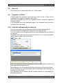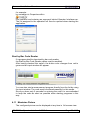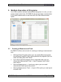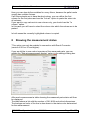
1
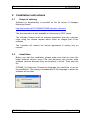
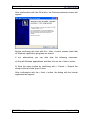
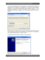
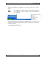
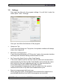
User and Installation Manual PC-DMIS – Operator Interface Version 2.2010.X.X © 2009 -2012 Hexagon Metrology GmbH – Germany User and Installation Manual Table of Contents 1 General information................................................................................. 4 1.1 Software objectives .......................................................................... 4 1.2 Software requirements ..................................................................... 4 1.3 License agreement, warranty and support ....................................... 4 1.4 License structure.............................................................................. 7 1.5 Pricing .............................................................................................. 7 2 Installation instructions ............................................................................ 8 2.1 Scope of delivery ............................................................................. 8 2.2 Installation ........................................................................................ 8 2.3 De-installation of software .............................................................. 13 3 Software configuration .......................................................................... 14 3.1 Language settings.......................................................................... 14 3.2 Settings .......................................................................................... 15 4 Single Execution of Programs ............................................................... 19 4.1 Launching Measurement Programs ............................................... 19 4.2 Setting Up the Startup Interface ..................................................... 19 4.3 Defining the Picture Size on a Grid ................................................ 20 4.4 Blocking of list programs. ............................................................... 20 4.5 Closing a program automatically after execution ........................... 20 4.6 Saving and loading a list ................................................................ 20 4.7 Importing a List (GUI)..................................................................... 20 4.8 New List ......................................................................................... 21 4.9 Program List Filter.......................................................................... 21 4.10 Load list automatically on start-up .............................................. 21 Start by Bar Code Reader ........................................................................ 22 4.11 Maximize Picture ........................................................................ 22 4.12 Aborting a Measurement ............................................................ 23 5 Multiple Execution of Programs ............................................................ 24 5.1 Creating a Measurement Task ....................................................... 24 5.2 Saving a Measurement Task ......................................................... 25 5.3 Locking Programs in the List .......................................................... 25 5.4 Assigning a picture to a group........................................................ 25 5.5 Setting up a quickstart list .............................................................. 26 5.6 Delete Programs from List ............................................................. 27 5.7 Sending a counter value to the PP................................................. 27 5.8 Sending a counter value to the PP................................................. 27 6 "Pallet run" of programs ........................................................................ 27 6.1 Menu option "Create PP configuration file" .................................... 29 7 Sending values to user defined variables into the program................... 31 8 Showing the measurement status ......................................................... 33 9 Administrator and Operator Mode ......................................................... 34 10 Information ........................................................................................ 36 10.1 About PC-DMIS OI ..................................................................... 36 10.2 License Information .................................................................... 36 11 Thank you .......................................................................................... 37 PC-DMIS – Operator Interface 2.2010.0.x Page 2 of 37 User and Installation Manual Note: In spite of all our efforts, we cannot guarantee that the documentation is completely free of errors. We welcome any constructive comments and suggestions. PC-DMIS – Operator Interface 2.2010.0.x Page 3 of 37 User and Installation Manual 1 General information 1.1 Software objectives This software was developed in order to provide a more friendly operator interface for the flow of program execution. Programs can be launched by mouse click or by using a bar code reader. 1.2 Software requirements Developed for the operating system: Windows XP (SP 3, Netframework4). Windows 7 (Netframework4). The software was not tested using other operating systems. Prerequisite for meaningful use of the software is the installation of PCDMIS, Version 2009 on the same computer. 1.3 License agreement, warranty and support PLEASE READ THE FOLLOWING TERMS AND CONDITIONS CAREFULLY BEFORE INSTALLING AND/OR USING THIS HEXAGONMETROLOGY GMBH SOFTWARE PRODUCT. BY INSTALLING THIS SOFTWARE ON YOUR COMPUTER, YOU ARE EXPRESSLY ACCEPTING THESE CONDITIONS. IF YOU DO NOT AGREE WITH THEM OR DO NOT UNDERSTAND THEM, YOU SHOULD RETURN THIS PRODUCT BEFORE INSTALLING IT. THIS LICENSE AGREEMENT IS THE COMPREHENSIVE AND EXCLUSIVE AGREEMENT BETWEEN THE USER AND HEXAGON METROLOGY GMBH. IT REPLACES ANY OTHER PROPOSAL OR PRIOR AGREEMENT IN WRITTEN OR OTHER FORM WITH RESPECT TO THIS SOFTWARE. Hexagon Metrology GmbH supplies this software and authorizes its application to the respective user only. Hexagon Metrology GmbH confirms that the software will operate substantially in accordance with the user manual. The user takes all responsibility for using this software to obtain the results intended by the user and for the application of the results obtained by this software. PC-DMIS – Operator Interface 2.2010.0.x Page 4 of 37 User and Installation Manual DEFINITION The term "this software" means all files supplied on the storage medium or as download or all copies, modified or otherwise derived from them, or any parts thereof. LICENSE This license agreement governs all possible releases, revisions or enhancements of this software. This software may be installed on one computer and may be copied once for backup purposes. This software may be transferred to a third party as part of a machine sale which includes the software license provided that the user does not retain copies thereof. The receiving party must accept the terms and conditions of this license and all copies not transferred to the same party must be destroyed. Transfers of ownership must be accompanied by written notification to Hexagon Metrology GmbH. The user is not entitled to decompile the software or otherwise adapt or modify the software. ANY ATTEMPTS OF THIS KIND OR THE UNAUTHORIZED TRANSFER OF THE SOFTWARE LICENSE WILL BE SUBJECT TO PROSECUTION. VALIDITY This license is effective until it is legally or automatically terminated. This license can be terminated by destroying all copies completely. It will also be terminated upon the violation of any part of this agreement by the user. The user agrees to destroy all copies completely upon expiration of license. WARRANTY WITH THE EXEPTION OF SPECIAL AGREEMENTS, THIS SOFTWARE IS PROVIDED “AS SEEN“, WITHOUT WARRANTY OF ANY KIND. HEXAGON METROLOGY GMBH DOES NOT GUARANTEE THAT THE SOFTWARE IS PROVIDED FREE OF DEFECTS. THE ONLY OBLIGATION HEXAGON METROLOGY GMBH HAS WITH RESPECT TO THIS LICENSE IS THE REFUND OF THE PRICE PAID FOR THE SOFTWARE LICENSE. IN NO EVENT IS HEXAGON METROLOGY GMBH OR ITS AUTHORIZED PARTNERS AND RESELLERS LIABLE FOR ANY CONSEQUENTIAL OR INCIDENTAL DAMAGES, INDIRECT LOSS, SPECIAL LOSS, LOSS OF PROFITS; LOSS OF BUSINESS, LOSS OF CONTRACTS, LOSS OF USE, ANTICIPATED SAVINGS OR LOSS OF DATA. Nothing in this license shall limit the liability of Hexagon Metrology GmbH for death or personal injury caused by negligence. SOFTWARE MAINTENANCE POLICY PC-DMIS – Operator Interface 2.2010.0.x Page 5 of 37 User and Installation Manual Hexagon Metrology GmbH or its authorized partners agree to provide a software maintenance agreement (SMA) including technical hotline support free of charge for a period of one year. Upon expiration of this period upgrades will be offered at a discount of 14% off the actual list price. NOTIFICATIONS All notifications to Hexagon Metrology GmbH in connection with this agreement shall be addressed to: Hexagon Metrology GmbH Siegmund – Hiepe – Straße 2-12 D-35578 Wetzlar or any other address agreed in writing. GOVERNING LAW This license shall be governed and construed in accordance with the substantive law of Germany. The court of Wetzlar (Germany) shall have jurisdiction. PC-DMIS – Operator Interface 2.2010.0.x Page 6 of 37 User and Installation Manual 1.4 License structure Hexagon Metrology GmbH provides the following license structure: Type of license Description Demo license License to try the software. This license is a free one-off offer License for 1 PC-DMIS dongle. Transferable to another PC with PC-DMIS dongle. License for three PC dongles in a separate plant or one business division within the plant. Transferable to another PC with PC-DMIS dongle. As per agreement. Single-user license Factory license Group license 1.5 License Availability maximum 3 months unlimited unlimited unlimited Pricing Please ask your PC-DMIS™ software supplier for the latest applicable prices. PC-DMIS – Operator Interface 2.2010.0.x Page 7 of 37 User and Installation Manual 2 2.1 Installation instructions Scope of delivery Software for downloading is provided on the ftp server of Hexagon Metrology GmbH. http://ftp.hexmet.de/PC-DMIS/PCDMIS Operator Interface/ The documentation is also available on this server in PDF format. The software license must be ordered separately from the customer order using the license request which forms an integral part of the software. The customer will receive the license agreement in writing only on request. 2.2 Installation Before you start the installation, please make sure that you have the latest software version (even CDs just delivered may contain older software versions because they are products in stock). Then start the file. PCDMIS_OI_Setup.exe. Choose the language you would like to use for the installation. This setting is independent of the language in which the software will run later. PC-DMIS – Operator Interface 2.2010.0.x Page 8 of 37 User and Installation Manual After confirmation with the OK button, the following welcome screen will appear: Before confirming this view with the < Next > button, please check that all Windows application programs are closed. If not, alternatively you can also take the following measures: a) Stop all Windows applications and then click on the < Next > button. b) Stop the setup routine by confirming with < Cancel >. Repeat the setup routine at a later point in time. After confirmation with the < Next > button, the dialog with the license agreement will appear. PC-DMIS – Operator Interface 2.2010.0.x Page 9 of 37 User and Installation Manual The license agreement is displayed in English and in German. Please read the agreement. If you do not comply with this agreement, abort the software installation at this point by clicking the < Cancel > button. Contact your software supplier. All agreements that differ from this must be defined in writing and must be signed by both parties. Accept the license agreement by confirming the option “I accept the license agreement”. Now you can continue the installation with the < Next > button. PC-DMIS – Operator Interface 2.2010.0.x Page 10 of 37 User and Installation Manual You can select which files will be taken into consideration during the installation in this dialog. The installation of all files is recommended. However, if the software had already been installed earlier, it is not absolutely necessary to install the character font for symbols or the sample files. After your selection, you can continue with the < Next > button. Please select the desired directory for the software installation here. Now all the settings required for the installation are complete. The installation can now be started with the < Install > button. A progress bar indicates the progress of the installation. PC-DMIS – Operator Interface 2.2010.0.x Page 11 of 37 User and Installation Manual When the installation is complete, you can close it with the < Finish > button. Note: The installation routine creates a link on the desktop of your computer as well as a folder in the program group of your computer. After having started the software, the license status is checked. If no license is found, a dialog opens automatically to assist you in creating a license request file LicenseRequestForPCDOI.dat PC-DMIS – Operator Interface 2.2010.0.x Page 12 of 37 User and Installation Manual Please send this file to the email address indicated by us: [email protected] You will receive a license file at the transmitted email address. This may take several days because the process is not fully automated. The license file is usually transmitted as a WinZip archive. If this is a problem for you, please note this in the email with your license request. Upon receipt of the license file, it must be unpacked into the directory where the converter is installed. 2.3 De-installation of software Generally, a software update or upgrade does not require any prior deinstallation. Should a software de-installation be desired at a later point in time, it may be run by calling up the uninstall routine in the start group. The manual deletion of folders may be necessary because there may be files in the installation directory which were not created by the converter installation program. In any case, you must execute the un-install routine first. The un-install routine does not remove registry entries, therefore, the existing settings can be used when re-installing the software. PC-DMIS – Operator Interface 2.2010.0.x Page 13 of 37 User and Installation Manual 3 Software configuration Before the software is used for the first time, it must be adapted to your environment. This first step requires administrator rights. 3.1 Language settings After the software has been installed and the license on your computer has been enabled, the language can now be selected. After the software has been started, the language can be selected under the "File" menu option. Select your desired language here. If a language is desired and is not available for selection, please contact the software supplier or manufacturer. PC-DMIS – Operator Interface 2.2010.0.x Page 14 of 37 User and Installation Manual 3.2 Settings Now open the dialog for the program settings. You will find it under the menu option Tools – Settings. Here you can define the behavior of the program. • Always on Top If you check the Always on Top option, the operator interface will always stay in the foreground. • Minimize on PP Execution If you check the Minimize on PP Execution" option, the operator interface will always be minimized during measurement run time. • Set Focus after Each Cycle on Bar Code Reader If the cursor shall be set into the bar code box after each measurement task launched by the Start by Bar Code Reader option which will re-arm this function for the next measurement task, you can check the Set Focus after Each Cycle on Bar Code Reader option. If you have started a measurement task by mouse click, the operator interface will be set on top after each measurement cycle. • Execute measurement with local copy When using this option, the program to be started will be copied into a pre-definable directory from which the programs are launched. PC-DMIS – Operator Interface 2.2010.0.x Page 15 of 37 User and Installation Manual You should use this option if the same measurement program is to be launched on multiple machines within one network. The Set Directory Path option specifies the target directory for the copy. After the measurement cycle, the copy will be removed from the directory • Global settings (Read/Write) You can use this option when you have multiple machines which are supposed to apply the OI with the same settings. Global settings will be saved and read in a pre-selected folder. The administrator must specify (or change, if necessary) the settings only once when this option is applied. After the settings are changed, all other machines will apply the new settings when restarted. To prevent others from changing the Global Settings, we recommend protecting this option with a password. This ensures that only the desired changes are saved globally. PC-DMIS – Operator Interface 2.2010.0.x Page 16 of 37 User and Installation Manual • Writing a Log File for Part Programs If a list of the programs started shall be created, you can check this option. The log file contains the date and time, start mode, user name as well as the program or status of program execution. The log file is an ASCII file ( PP.log ) and can be found in the directory to which PC-DMIS OI is installed. You can specify a variable time with delay time when starting the program with bar code scanner. You can use this variable for reading in 2 or more codes. If you don't set the value higher, you have only 2 seconds to enter or scan a complete code before the measurement cycle is started. • Bar Code freely Selectable The Bar Code freely Selectable option is a setting reserved to the administrator. If it is enabled and a password has been assigned for the settings, any operator can check or uncheck the Start by Bar Code Reader option at any time. If this option is not enabled, the saved setting of this option will be activated which can only be changed by the administrator. • Always confirm programs started with bar code reader. After enabling the function, the user will have to confirm each program step of the measuring job if it has been started with bar code reader. This setting is only enabled if the application has been locked by the administrator. • Show Picture when Starting by Bar Code Reader After having checked this option, the picture assigned to a program will be shown when starting the program. The length of time it is displayed for can be specified under Length of Display Time. • Disabling manual selection of part programs. The system administrator may decide only to allow programs which have been set-up on the OI user interface to be started. PC-DMIS – Operator Interface 2.2010.0.x Page 17 of 37 User and Installation Manual This function disables all possibilities of manual measurement program selection. This setting is only enabled if the application has been locked by the administrator. • Set Directory Path The Set Directory Path option specifies the main directory for lists. If a user likes to save or load a list or a measurement task, PC-DMIS OI offers the Specified Folder by default. However, it is also possible to select another folder. If no directory folder has been specified, the last folder selected will be proposed with the next operation. • Delete Directory Path You can delete the pre-defined path with the Delete Directory Path option. • Color – Multiple Execution The colors of the program listings can be defined in Color – Multiple Execution area of the Multiple Execution registry. The text color of the program list is defined by Marked and Unmarked entries. While performing the measuring task the background color is controlled by the entries Measurement completed and Measurement in Progress. PC-DMIS – Operator Interface 2.2010.0.x Page 18 of 37 User and Installation Manual • PC-DMIS on Program Execution If the PC-DMIS on Program Execution, Hidden option is enabled, PCDMIS will be not visible as long as PC-DMIS OI remains open. If this option is not enabled, the saved setting of this option will be activated which can only be changed by the administrator. • Save copy of the program after run. After activation of the function, the copy is made after run a pp. The copy will be created in the part program directory, or in a variable path, if the function “Variable main path” was checked. It’s also possible to created subfolders (program name, year, month, day…) in the same directory. The copy is saved under the name "Date__Time____CopyOf_Partprogramname.PRG. • List of processes If additional software is started within the program, and the program can only be closed once the software is also closed (such as QDAS or result converter), it can also be installed in the list of processes. After having opened the current list with Show / Edit, you can add new processes to be monitored. To add a new entry, right-click on the desired line and select the process you wish to add. 4 Single Execution of Programs 4.1 Launching Measurement Programs PC-DMIS allows the execution of programs in single mode by accessing the File menu -> Start Program option and selecting the measurement program to be executed. You start the program previously configured in the program list with a mouse click on the picture button or in the Start by Bar Code Reader mode, where the measurement cycle is launched by bar code reader. Also a program started by bar code reader must be configured. Note! 4.2 The buttons for starting the program manually are disabled in the Bar Code Mode. Setting Up the Startup Interface Programs must first be configured if you like working with the grid interface. The configuration of programs is quite easy. You only have to right-click on the line you want to allocate in the Program column of the grid and to select the program. PC-DMIS – Operator Interface 2.2010.0.x Page 19 of 37 User and Installation Manual After having selected a program, you can assign pictures and codes. Any changes in the list can be done in the same way. You must only right-click on the cell for modification. Only an administrator is allowed to modify settings. When a program in a list must be created between existing programs, you must insert another line. It happens with a double click on the lines title area. Then, a program can be newly created. 4.3 Defining the Picture Size on a Grid You can change the size of the picture included in the list at any time. Drag the picture column with the mouse to the desired width, the height will be adjusted to a 3:2 ratio (W:H). 4.4 Blocking of list programs. To block a program in the list. You have to click the row in the grid, and then press the F3 function key. You must use the F3 Again, to end lock the program. The function can be used only in administrator mode. 4.5 Closing a program automatically after execution You may not always want a program to close automatically after it has been executed. If you want a program to close automatically, click on the "Close part programs automatically after execution" option. If this option is disabled, the program will remain open until it is closed manually or another program is launched. 4.6 Saving and loading a list The installed program lists can be saved under any name with the "List > "Save as …“ option and loaded with the "List -> Load“ option. 4.7 Importing a List (GUI) The List -> Import (GUI) menu option allows the import of additional older lists. PC-DMIS – Operator Interface 2.2010.0.x Page 20 of 37 User and Installation Manual 4.8 New List The current list is cleared with the List -> New option. 4.9 Program List Filter If the program list becomes very long from time to time, a filter can be configured by using the Program Filter option. Only those programs will then be displayed which include the specified character string. If all programs are to be displayed again, the character string must be deleted in the Filter area. 4.10 Load list automatically on start-up The user can load a list by argument-selection when starting the OI. This is possible by assigning an argument to the desired list. You can create a list of arguments which can subsequently be recalled on request. Arguments and links are set-up with the “Set up, list of start commands” option, which is part of the List menu. Enter the argument into the command column in the setup window and then right-click to select the list. On completion, the list will be written by confirming via the Apply button. When creating a list, the latest status will be displayed when starting this function from the menu. The operations thus created can be recalled through an automation or Windows operation, PC-DMIS – Operator Interface 2.2010.0.x Page 21 of 37 User and Installation Manual for example: by navigating to Properties within this operation and entering an argument behind Operator Interface.exe. The list assigned to the operation will then be opened when starting the application. Start by Bar Code Reader If a program shall be launched by bar code reader, the Start by Bar Code Reader option must be enabled. After having checked this option, the button color changes from red to green and an input window will appear. You can also start a measurement program directly from the list by using the input window. The code must be entered manually for this scope. Since you have only 2 seconds for entering the code it is recommended to keep the code as short as possible when starting programs in this way. 4.11 Maximize Picture The configured picture can be displayed at any time in full-screen view. PC-DMIS – Operator Interface 2.2010.0.x Page 22 of 37 User and Installation Manual To do this, right-click on the border of the cell which contains the picture. Another click with the right or left mouse button closes the window again. 4.12 Aborting a Measurement When the operator interface is used in the operator mode and the program is aborted it will be be closed. In the administrator mode you will also be prompted if the program shall be closed again. PC-DMIS – Operator Interface 2.2010.0.x Page 23 of 37 User and Installation Manual 5 Multiple Execution of Programs If you like to perform several measurement programs in a row, you can create a task control lists. PC-DMIS OI will process them consecutively. A list based measurement is launched with the Start Measurement option. 5.1 Creating a Measurement Task PC-DMIS OI offers various tools for creating or loading a measurement task: • With the Select Program button you can recall different programs from different locations. After having selected all programs you can close this dialog box with Cancel. • If you like to load all programs from a selected folder you can choose the Measurement Task -> Load Programs from Folder" menu option. • With the Measurement -> Load menu option you can recall measurement tasks previously saved. • With the Measurement Task -> Import (GUI) option you can import old pallet lists. PC-DMIS – Operator Interface 2.2010.0.x Page 24 of 37 User and Installation Manual 5.2 Saving a Measurement Task It the measurement task is a recurring listing, the measurement task should be recorded. In this way, the operator can always recall and use the recorded files. After having selected the Measurement Task -> Save As menu option you must decide, if you like to save only the programs highlighted in the list or all programs. Use the OK button to confirm your selection. Then you can select the list name and location. 5.3 Locking Programs in the List If you wish to cancel the measurement for a program within one measurement task it can be locked with the right-hand side button of the grid. The line will then be displayed in another color (see chapter 3.2). 5.4 Assigning a picture to a group If you are working with groups and saving them as lists, you can assign a picture to each group which then will be displayed in the main window of this group when activated. Simply right-click on the picture to zoom it in. PC-DMIS – Operator Interface 2.2010.0.x Page 25 of 37 User and Installation Manual 5.5 Setting up a quickstart list Very often clients wish to access saved groups by using a picture or by mouse-click. Pre-requisite for this function is the creation of a list. The quickstart list is enabled with the "Multiple run" option. Creating such a list is comparable with setting up a list in the single run area. The only exception is that you first have to create the "Saved list". If you create a saved list, the picture saved with the selected list will be shown. Right-click on the picture if you want to edit and alter it. The picture will only be changed in the quickstart list; the entry in the saved list will remain unchanged. Click on the picture line if you wish to recall a list created in this manner. You can also assign a bar code to a group you have created in the list. The bar code reader can then load the group with this code. A list can be loaded by pressing the hot key F1, then the code is read with a scanner and the list is loaded. PC-DMIS – Operator Interface 2.2010.0.x Page 26 of 37 User and Installation Manual 5.6 Delete Programs from List Programs can be removed from a measurement task by highlighting the whole line. 5.7 Sending a counter value to the PP If you want to use the counter value from the list in the program, use the "Send counter value to the program" function. If you checkmark this option, each time you start the program, it will search for a variable, and, when found, will assign the current value from the table to the variable. For this purpose, a variable definition called “CURRUN” must be entered into the program. ASSIGN/CURRUN=1 5.8 Sending a counter value to the PP If you want to send comments out of the application into the measurement program you can use the "Send a comment to the PP" option. If you checkmark this option, each time you start the program, it will search for a variable, and, when found, will assign the current value from the table to the variable. For this purpose, a variable definition called "CURCOMMENT” must be entered into the program. ASSIGN/CURCOMMENT=“TESTTEXT“ 6 "Pallet run" of programs Those who want to execute a program within a fixture pattern (such as offset 4x in X direction around a'mm 100) know how demanding such a task can be for programmers. The task is further complicated if offsets are carried out in a second direction and if different values are sent into the program with every single run, and, for example, if one part of the program is not to be measured. To keep such a task as simple as possible we have developed the "pallet run" dialog for the "Operator Interface" which can meet the requirements of all tasks listed above. Pre-requisites for a fully functioning pallet run are: PC-DMIS – Operator Interface 2.2010.0.x Page 27 of 37 User and Installation Manual - The order of alignment defining the offset direction must be set on top of the measurement program. It must be followed by the command MODUS-CNC. The first features for CNC features within the program must be programmed after this command. Before executing the created measurement task the selected program will be copied. A structure will then automatically be written into the copied program which allows a variable execution of the measurement task. This structure will be inserted directly behind the command MODE/CNC. You can select an external alignment as offset datum. If no datum has been selected, PC-DMIS OI will use the last alignment preceding the MODE/CNC command for the offsets and transfer it to an HA alignment, which then will be transfered to the first alignment after the MODE/CNC command. If you choose an external alignment for calculating the offsets, the calculation will be based only on the origin of the original alignment. The part direction on the fixturing results from the alignment coming directly before the MODE/CNC command. If an external alignment is used, the name of the file in which the alignment was saved must be identical with the name of the alignment. After having started the measurement run, values are sent to variables definable in the software as well as to fixed variables, which define the offsets of the fixturings. ASSIGN/VX=0 ASSIGN/VY=0 ASSIGN/VZ=0 ASSIGN/CURRUN=1 Offset in X to datum Offset in Y to datum Offset in Z to datum Current fixturing After having carried out a measurement with enabled "PP Save Copy" option, PC-DMIS OI will create the name of the copy consisting of: - date and time - information about direction and (rounded) values of offsets - Fixture number - information about current position with (rounded) offset values - program name If a measurement task is aborted it can be continued, starting from the last fixture. For this purpose, the user must enter the current position at PC-DMIS – Operator Interface 2.2010.0.x Page 28 of 37 User and Installation Manual which it is to be measured into the area "Current run" of the main window (see sketch for number). The number of parts to be measured is defined in the "Number of parts" area. If you don't enter your settings in this area, entries will be calculated automatically from the following parameters: - "Number of offsets" in fixture direction - "Number of offsets" in row direction - "Current run" Offsets numbers and sizes can be entered into the fields "Number" and "Distance" (Offset). The offsets can be defined in X, Y and Z directions. If you want to define the offset direction, click on the letter of the axis letter until the desired axis pairing is reached. First set up the main direction (direction of fixtures). After having set up the X axis for example, you can select Y or Z as secondary direction (direction of rows) only. If the main direction is Y, then X or Z and so on. Directions will be run in the following order: from first to last fixture of the main direction (first row) -> from last to first fixture of the main direction (second row) ... and so on. (shortest paths, see sketch). 6.1 Menu option "Create PP configuration file" As described above, PC-DMIS OI allows the definition of areas and variables in every program. The desired program must first be selected in the OI, because all variables are assigned individually and separately to every program. PC-DMIS – Operator Interface 2.2010.0.x Page 29 of 37 User and Installation Manual After having selected the program, it is shown in the main window and you can access the configuration menu with "File“ -> "Create PP configuration file". With this menu you can define variables and areas, which are then populated with values by the program control. The column: "List of variables" is used to declare variables populated with pre-defined values by the user. "List of areas in the PP" is used to declare the areas used in the program. The applicaton will then display an area declared in such a manner with a check box through which an area can be enabled and thus released for measurement. However, this is only possible if these areas are part of the measurement program. If you want to adopt data from an already defined program you can use the "Import data" option. With the "Delete PP file" option you can remove an existing variable assignment. Example for programming an area: PC-DMIS – Operator Interface 2.2010.0.x Page 30 of 37 User and Installation Manual If the variable "PRINT" is declared in the "List of variables" column, this area is shown on the OI and the program is executed based on the decisions. If the box is enabled, the value 1 is sent to the program variable "PRINT“. Thus, the PRINT area is executed in the program. IF/PRINTING==1 PRINT/REPORT,EXEC MODE=END,$ TO_FILE=OFF,AUTO=1,$ TO_PRINTER=OFF,$ TO_DMIS_REPORT=OFF,FILE_OPTION=OVERWRITE,FILENAME=,$ REPORT_THEORETICALS=NONE,REPORT_FEATURE_WITH_DIMENSIONS= NO,$ PREVIOUS_RUNS=DELETE_INSTANCES END_IF/ If you want to send various values to program variables, these must be declared prior to their execution. After this, they will be sent to the program when the measurement task is carried out. 7 Sending values to user defined variables into the program If you wish to send values to user defined variables you must enable the desired area in the settings dialog box. PC-DMIS – Operator Interface 2.2010.0.x Page 31 of 37 User and Installation Manual After this, you can individually enter settings for each single area. If you want to enter variables by query, a related dialog box is shown after starting the program. Single and multiple mode: The multiple mode requires the entry of values by the user after each program launch from the list. It is therefore not possible to display an input form for the run as a whole (as for the pallet run), because each program can have individual variable declarations. Pallet mode: PC-DMIS – Operator Interface 2.2010.0.x Page 32 of 37 User and Installation Manual Here you can also define variables for every fixture, because the pallet mode usually has multiple fixtures. If all fixture places are to have identical values, you can define the first column for the first place and use the "Into all" option to paste the value into all columns. If you want to copy values into one column only, you should use the "In column" option. In this case you will have to select the column into which the values are to be pasted. In both cases the currently highlighted column is copied. 8 Showing the measurement status *This option can only be enabled in connection with Result Converter (version 4.201x.x.21 and higher). If you would like to see a short overview of the measured parts, you can enable the "Status(measurement) display“ option in the settings dialog box. After each measurement a table showing the measured parts status will then be displayed. The table shows a list with the number of OK, NOK and critical dimensions. The background color of the line is also drawn in the status color determined for the measurement. PC-DMIS – Operator Interface 2.2010.0.x Page 33 of 37 User and Installation Manual The dimension output file is opened by double-clicking on the program name column. In case of an output combination of the Complete and OOT values, the correction file will also be opened when you double-click on the NOK column. 9 Administrator and Operator Mode There are two ways for using PC-DMIS: • Administrator Mode (access to all settings). • Operator Mode (The operator is only allowed to do selected modifications, but the access to basic application settings such as the modification of lists is denied.) A password must be assigned for enabling the operator mode. You do this by selecting the Tools -> Safety menu option. PC-DMIS OI will switch into the operator mode after the password has been entered and repeated. The background color of the menu bar is set to water green in the administrator mode which gives a quick overview to which mode is currently enabled. PC-DMIS – Operator Interface 2.2010.0.x Page 34 of 37 User and Installation Manual The color changes to grey in the operator mode. PC-DMIS – Operator Interface 2.2010.0.x Page 35 of 37 User and Installation Manual 10 10.1 Information About PC-DMIS OI Key information on PC-DMIS OI is to be found under About -> About PCDMIS OI. 10.2 License Information By selecting the About -> License Information menu option the License menu is recalled that contains all key information on the licenses. If you like to order a new license the dialog box for requesting a new license can be accessed directly from this menu. The license request must be created using the dongle with which the software is used. PC-DMIS – Operator Interface 2.2010.0.x Page 36 of 37 User and Installation Manual 11 Thank you Hexagon Metrology GmbH would like to thank you for your interest in this product. We will continue to implement proposals for improvement resulting from practical experience with our software products. We would especially like to express our thanks to those customers who have supported us with their proposals and tips during the creation of this product – and who still are giving us their continued support. PC-DMIS – Operator Interface 2.2010.0.x Page 37 of 37