1
User Manual
PC-DMIS – Q-DAS Converter Version 2.3.x
Copyright 2002-2010 Hexagon Metrology GmbH - Germany
User Manual
Contents
1.
General information .......................................................................................... 3
1.1. Software objectives ...................................................................................... 3
1.2. Software requirements ................................................................................. 3
1.3. Software warranty and support..................................................................... 3
2. Installation instructions .................................................................................... 4
2.1. Shipping contents......................................................................................... 4
2.2. Installation .................................................................................................... 4
2.3. Uninstalling the software .............................................................................. 4
3. Using the software ............................................................................................ 5
3.1. Language setting.......................................................................................... 5
3.2. Creating the measurement program in PC-DMIS......................................... 5
3.3. Launching the PC-DMIS – Q-DAS Converter software ................................ 9
3.4. User interface of the PC-DMIS – Q-DAS Converter software ...................... 9
3.5. Configuration of the converter .................................................................... 10
3.6. Offline conversion....................................................................................... 16
3.7. ONLINE conversion.................................................................................... 19
3.8. Execute the converter from the PC-DMIS part program............................. 19
3.9. List of supported Q-DAS K fields................................................................ 21
3.10.
List of supported dimension types in PC-DMIS™ ................................... 23
Note:
Despite every effort, we are unable to fully preclude the possibility of errors in the
documentation. We will be pleased to receive any hints or suggestions you may have.
We would like to express our special thanks to the Q-DAS company for their excellent
cooperation during development of this converter. We would also like to thank all our
customers who provided us with very good support with test and information during
development.
Q-DAS
Gesellschaft für Datenverarbeitung und Systemtechnik mbH
Eisleber Strasse 2
D-69469 Weinheim
Germany
PC-DMIS – Q-DAS Converter Version 2.3.x
Page 2 of 23
User Manual
1. General information
1.1. Software objectives
This software has been developed to allow generation of qs-STAT data under
the PC-DMIS software package, Version 3.5 and higher.
The converter allows manual conversion (OFFLINE) or automatic conversion
from the part program (ONLINE).
1.2. Software requirements
The software has been developed for the Windows NT 4.0, Windows 2000 and
Windows XP operating systems. No software tests have been conducted with
other operating systems.
The tests of compatibility of the data generated with qs-STAT were conducted
with version qs-STAT Millennium. However, in accordance with Q-DAS®, the
format may also be used for less recent versions.
PC-DMIS Version 3.5 or higher must be installed on the same computer in
order to be able to use the software practically.
1.3. Software warranty and support
See current license.txt file in the installation folder of the software.
PC-DMIS – Q-DAS Converter Version 2.3.x
Page 3 of 23
User Manual
2. Installation instructions
2.1. Shipping contents
The software is available for download on the DEA – Brown & Sharpe GmbH ftpServer.
ftp://ftp.dea3d.de/DEA-Addon/PC-DMIS-Q-DAS_Converter_Version_2
or
http://ftp.dea3d.de/DEA-Addon/PC-DMIS-Q-DAS_Converter_Version_2
2.2. Installation
To install the software execute the setup .exe file. Please follow the commands
of the setup routine carefully.
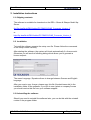
After starting the software, the system will check automatically if a license exist.
Otherwise you will see the following dialog which allows you to generate a
license request:
The menu Language / Sprache allows to change between German and English
language.
After you receive your license please copy this file (KundenLizenz.dat) in the
installation folder of the software. If you like to use a plant or company license
you should receive this file from your software supplier.
2.3. Uninstalling the software
Should you need to uninstall the software later, you can do this with the uninstall
routine in the program folder.
PC-DMIS – Q-DAS Converter Version 2.3.x
Page 4 of 23
User Manual
3. Using the software
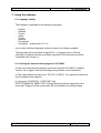
3.1. Language setting
The Software is available in the following languages:
-
English
German
French
Italian
Czech
Spanish
Portuguese
Hungarian (starting from 2.3.11)
If you need a different language, please contact your software supplier.
The language can be selected using the File – Language menu. With the
selection you decide also the axis letters (specially if the converter should be
compatible with Version 1).
3.2. Creating the measurement program in PC-DMIS
Create your measurement program as normal using the PC-DMIS software,
Version 3.5 or higher. Note the following during creation of the evaluation:
a) The output option must be set to “STATS” or “BOTH” for evaluations which are
to be included in the statistics.
b) Command “STATS/ON” , STATS/OFF and
STATS/TRANSFER ,DIRECTORY={Target directory} will be supported, if the
check box “Support of Stat commands” will be activated in the Setup dialog.
PC-DMIS – Q-DAS Converter Version 2.3.x
Page 5 of 23
User Manual
If this check is activated, the converter will not read dimensions or other
commands before the STATS/ON command is included in the part program.
The STATS/OFF command will be something like a pause command, you can
activate the data transfer to the converter with the STATS/ON command again.
All commands between STATS/OFF and STATS/ON will not be read from the
converter.
The STATS/TRANSFER command will allows you to define a target directory in
the part program. This target directory will override the converter default settings.
The command will also close the Online process. Depending on the start up
option (/i or /a) the export of the Q-DAS ASCII file will start automatically (/i) or
not (/a).
PC-DMIS – Q-DAS Converter Version 2.3.x
Page 6 of 23
User Manual
c) Trace fields are supported for the following K-fields:
Key
/0
Description
Length Type catalog basedt Customer description
DFD
DFX
Remarks
Values / add. Data
K0006
Batch number
14
A
K0007
Cavity number
5
I
X
"#" must be used
K0008
Operator name
X
K0009
Text
K0010
Machine number
K0012
Gage number
K0053
Order
K1021
Manufacturer No.
20
A
DFD
K1022
Manufacturer name
80
A
DFD
K1031
Material number
20
A
DFD
K1032
Material description
40
A
DFD
K1041
Drawing number
30
A
DFD
K1042
Drawing Amendment
20
A
DFD
K1052
Contractor Name
40
A
DFD
K1053
Order
40
A
DFD
5
I
255
A
5
I
X
5
I
X
20
A
DFX
Parts data
Characteristics data
K2001
Characteristic number
20
A
K2005
X
Characteristics class
1
I
K2006
X
Controll item
1
I
K2320
Contract number
20
A
K2401
Gage number
40
A
K2402
Gage description
80
A
255
A
Module
AS/PC/PV
definierte
Feldinhalte
definierte
Feldinhalte
DFD
only for all
characteristics
only for all
characteristics
only for all
characteristics
Additional Trace fields
FileName
String for file name
In PC-DMIS™ one dimension includes sometimes more then one characteristic.
Then you can use for K2005 or K2006 more then one value separated by
comma. The value is used for the next characteristic in the part program. If you
use more then one value (separated by comma) then each value is for the next
characteristic. In the following example program you can see this by the different
colors.
If you use the Trace commands, you should disable the Keys in the user
interface using the Setup for Q-DAS Keys.
PC-DMIS – Q-DAS Converter Version 2.3.x
Page 7 of 23
User Manual
DISPLAYPRECISION/3
TRACEFIELD/NO_DISPLAY,LIMIT=1 ; K2005/0 : 3
TRACEFIELD/NO_DISPLAY,LIMIT=1 ; K2006/0 : 1
COMMENT/REPT,LOC1 / X-Axis for Hole 204
,LOC1 / Y-Axis for Hole 204
,LOC1 / Z-Axis for Hole 204
,LOC1 / Diameter for Hole 204
DIM LOC1= LOCATION OF CIRCLE CIR1 UNITS=MM ,$
GRAPH=OFF TEXT=OFF MULT=10.00 OUTPUT=BOTH
AX NOMINAL +TOL
-TOL
MEAS
DEV
OUTTOL
X 203.199 0.000 0.000 203.199 0.000 0.000 ----#---Y 76.200 0.000 0.000 76.200 0.000 0.000 ----#---Z
0.000 0.000 0.000 0.000 0.000 0.000 ----#---D 25.400 0.000 0.000 25.400 0.000 0.000 ----#---END OF DIMENSION LOC1
TRACEFIELD/NO_DISPLAY,LIMIT=15 ; K2005 : 2,2,2,2
TRACEFIELD/NO_DISPLAY,LIMIT=15 ; K2006 : 0,0,1,1
COMMENT/REPT,LOC2 / X-Axis for Hole 204
,LOC2 / Y-Axis for Hole 204
,LOC2 / Diameter for Hole 204
,LO C2 / True Position for Hole 204
DIM LOC2= TRUE POSITION OF CIRCLE CIR1 UNITS=MM ,$
GRAPH=OFF TEXT=OFF MULT=10.00 OUTPUT=BOTH DEV PERPEN CENTERLINE=OFF DISPLAY=DIAMETER
AX NOMINAL +TOL
-TOL
BONUS
MEAS
DEV
OUTTOL
X 203.199
203.199
0.000
Y
76.200
76.200
0.000
DF 25.400 0.000 0.000 0.000 25.400 0.000 0.000 ----#---TP
MMC
0.000
0.000
0.000
0.000 ----#---END OF DIMENSION LOC2
DISPLAYPRECISION/4
DIM LOC3= TRUE POSITION OF CIRCLE CIR1 UNITS=MM ,$
GRAPH=OFF TEXT=OFF MULT=10.00 OUTPUT=BOTH DEV PERPEN CENTERLINE=OFF DISPLAY=DIAMETER
AX NOMINAL +TOL
-TOL
BONUS
MEAS
DEV
OUTTOL
X 203.1990
203.1991 0.0001
Y 76.2000
76.2000 0.0000
DF 25.4000 0.0000 0.0000 0.0000 25.4001 0.0001 0.0001 -------->
TP
MMC 0.0000
0.0000
0.0002 0.0002 -------->
END OF DIMENSION LOC3
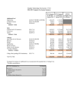
d) You can insert a report comment in front of each dimension. This comment is
then saved in Q-DAS key field K2900. It cannot be changed during the runtime.
Then save your measurement program without quitting the program.
PC-DMIS – Q-DAS Converter Version 2.3.x
Page 8 of 23
User Manual
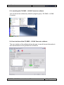
3.3. Launching the PC-DMIS – Q-DAS Converter software
You can launch the software by default in program group \ PC-DMIS – Q-DAS
Converter.
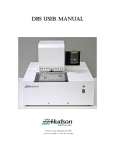
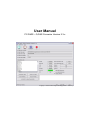
3.4. User interface of the PC-DMIS – Q-DAS Converter software
The user interface of the software allows the user to see all his part information’s
and results before he will generate the Q-DAS file.
PC-DMIS – Q-DAS Converter Version 2.3.x
Page 9 of 23
User Manual
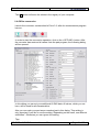
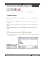
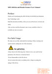
3.5. Configuration of the converter
In order to match the converter to the relevant requirements of the application,
launch menu item “Setup” in the “Preferences” menu.
In this dialog, you can choose the directory to which your Q-DAS files are to be
saved.
The following options are possible:
•
Use PC-DMIS Part Program Folder
If you select this option, the software will save the Q-DAS ASCII files in the
same folder as the PC-DMIS part program.
•
Select an individual Folder during each execution
During each part program execution, the operator can select a folder,
where the software will save the Q-DAS ASCII files.
•
Use Default folder
If this option is used, you need to select the default folder in this dialog.
There is also a possibility to use a specific folder name from the command line in
the PC-DMIS part program (see chapter 3.8).
In the “Q-DAS ASCII File Name” frame you can configure the file name, which
will be used for the Q-DAS ASCII file. Part Name, Revision Number and Serial
Number are values which are offered from the PC-DMIS part program header.
Date and Time are used from the computer system during the file will be
generated. The selected separator will be used between each of the other
PC-DMIS – Q-DAS Converter Version 2.3.x
Page 10 of 23
User Manual
settings. If you didn’t use the Date and Time setting, you need to use the 4 digits
counter, otherwise the software will override the old file.
The GM file name rules will create the following file name format:
{string from Trace field ‘FileName’}_MMDDhhmmss.dfd
or
MMDDhhmmss.dfd
In the “Program Settings” frame are some settings, which allows the operator to
configure the software in the best way for his application.
•
Multi Line Comments
Comments can be used as additional explanation of the individual
characteristics. The respective comment is firmly bound to a characteristic.
In order to be able to reach this, some rules in the PC-DMIS Program must
be considered.
Whether a comment is used or not, is dependent on the type of the
comment and the position in the measuring program.
•
•
•
The comment must be a protocol comment
The comment must stand directly before the dimension.
Comments of several lines are considered up to 20 lines. If more
than 20 lines were used, the remaining lines are ignored.
Dependent on the status of the check box you will receive different
interpretations of PC-DMIS protocol comments with several lines.
Around this to describe in detail you find in the following two examples:
Example 1:
COMMENT/REPT,Comment for X-Axis
,Comment for Y-Axis
,Comment for Z-Axis
,Comment for D-Axis
MOVE/CLEARPLANE
DIM 1= LOCATION OF CIRCLE KREIS1 UNITS=IN ,$
GRAPH=OFF TEXT=OFF MULT=10.00 OUTPUT=BOTH
AX NOMINAL +TOL
-TOL
MEAS
MAX
MIN
DEV
X
1.000
0.004 -0.004
1.000
1.441
0.559
0.000 ----#---Y
1.000
0.004 -0.004
1.000
1.441
0.559
0.000 ----#---Z
0.000
0.004 -0.004
0.000 -0.079 -0.157
0.000 ----#---D
1.000
0.008 -0.008
1.000
1.000
1.000
0.000 ----#---END OF DIMENSION 1
PC-DMIS – Q-DAS Converter Version 2.3.x
Page 11 of 23
User Manual
This comment is not used, since MOVE/CLEARPLANE stands a command
between the comment and the characteristic.
Example 2:
COMMENT/REPT,Comment for X-Axis
,Comment for Y-Axis
,Comment for Z-Axis
,Comment for the D-Axis
DIM 1= LOCATION OF CIRCLE KREIS1 UNITS=IN ,$
GRAPH=OFF TEXT=OFF MULT=10.00 OUTPUT=BOTH
AX NOMINAL +TOL
-TOL
MEAS
MAX
MIN
DEV
X
1.000
0.004 -0.004
1.000
1.441
0.559
0.000 ----#---Y
1.000
0.004 -0.004
1.000
1.441
0.559
0.000 ----#---Z
0.000
0.004 -0.004
0.000 -0.079 -0.157
0.000 ----#---D
1.000
0.008 -0.008
1.000
1.000
1.000
0.000 ----#---END OF DIMENSION 1
The comment is used, since no command between the comment and the
characteristic will be placed. Only Trace commands and decimal precision
commands can be placed between the comment command and the
dimension command.
If Multi Line Comments will be active, you will get the following result:
Dimension
1.X
1.Y
1.Z
1.D
Comment
Comment for X-Axis
Comment for Y-Axis
Comment for Z-Axis
Comment for D-Axis
If Multi Line Comments will be not active, the following interpretation will be used:
Dimension
1.X
1.Y
1.Z
1.D
Comment
Comment for X-Axis / Comment for Y-Axis / Comment for Z-Axis / Comment for D-Axis
Comment for X-Axis / Comment for Y-Axis / Comment for Z-Axis / Comment for D-Axis
Comment for X-Axis / Comment for Y-Axis / Comment for Z-Axis / Comment for D-Axis
Comment for X-Axis / Comment for Y-Axis / Comment for Z-Axis / Comment for D-Axis
•
Check for existing CFG File
If this setting is used, the converter check, depending of the name of
the part program an the revision number, if a CFG file exists. In this
CFG File the operator can save the last settings of the additional QDAS data.
•
Use Q-DAS Position Calculation
If this check box is marked, the Converter will use K2008, K2030
and K2031 for Position dimensions. If this structure is used, Q-DAS
knows, which ordinates are used for which dimension. The
calculation of the true position value will be done from qs-STAT®
PC-DMIS – Q-DAS Converter Version 2.3.x
Page 12 of 23
User Manual
•
Depending on the result, use different subfolders
If this setting is active, the converter will build the following subfolder
in the target folder:
a) FirstParts
b) PartOK
c) PartOOT
Results from parts, which are measured the first time, will be saved
in the FirstPart folder (independent off the result).
In the PartOK folder the software will save a copy of the Q-DAS
ASCII files, if all values are in tolerance. This should be the group of
parts, which are delivered.
In the PartOOT folder the converter will save a copy of the Q-DAS
ASCII files, if one or more values are out of tolerance.
If you measured a part a second time, you should mark it as a
reworked part. The Q-DAS ASCII files will be saved (depending on
the result) only in the PartOK or PartOOT folder.
•
Use Q-DAS Converter V. 1 Axis Designations
If this option is checked the Converter will use compatible values for
K2001 against the Version 1.x.x
•
Use default values for Q-DAS data
If this option is checked, the converter offers the same settings for
the add. Q-DAS data for all part programs. The defaults have to be
saved one time in the dialog.
•
Minimize the dialogue during execution
This setting allows the operator to decide, if the dialogue will be
minimized during the execution.
•
Attribute
If a dimension is not marked in the PC-DMIS part program, the
converter will set the Attribute (K0002) to 255 or 256. The meaning
of this values you can find in your Q-DAS documentation. If the
dimension command is marked, the converter will use the value 0.
•
Q-DAS File structure
The converter can create Q-DAS ASCII files in the following formats:
a) DFQ
b) DFD and DFX
IMPORTANT: If you like to use Q-DAS Monitoring software, you
must use DFD and DFX.
OK
Store the values in the registry of your computer
(HKEY_LOCAL_MACHINE \ SOFTWARE \
DEAGERMANY \ PCDQDAS \ Settings) and close the
dialog.
PC-DMIS – Q-DAS Converter Version 2.3.x
Page 13 of 23
User Manual
Cancel
Cancel will close the dialog without saving the values.
Export Settings This button will save the settings in an external file
(OutputFile_Settings.cfg) in the installation folder of
the software. This file can be used for the
configuration of a second systems or if you need to
work with different settings.
Import Settings This button will import the OutputFile_Settings.cfg file.
Advanced Settings This button will open a dialog for special settings to
fit the converter with your qs-STAT package.
Please contact your statistical expert before changing this parameters.
Output file settings for Q-DAS Monitoring
In this dialog you can define a folder, where the converter will store the files for
the Q-DAS Monitoring software. Inside of the selected folder the converter will
create an individual subfolder for each part program. For each part program the
converter will save one DFD file (00000001.dfd) and for each execution a DFX
file (00000001.dfx … 00009999.dfx). The converter will use the first free number
for the DFX file.
PC-DMIS – Q-DAS Converter Version 2.3.x
Page 14 of 23
User Manual
Q-DAS Settings
Depending on the customers application Q-DAS often use some K-Fields with a
different description as the standard. In this dialog you can fit the converter
interface with the used descriptions in qs-STAT®.
The button Export Settings will save the values in the file QDAS_Settings.cfg in
the installation folder of the converter software. The OK button will save the
values in the registry of your computer.
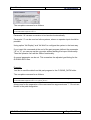
Setup für Q-DAS Keys
In this dialog you can configure, which K-Fields should be used by the operator.
If the check is active, the K-Field is enabled in the operator interface, otherwise
the Field is disabled.
You must disable all K-Fields for which you like to use TRACE commands in your
part program.
PC-DMIS – Q-DAS Converter Version 2.3.x
Page 15 of 23
User Manual
The OK button will save the values in the registry of your computer.
3.6. Offline conversion
Launch the converter, as described in Point 3.3, after the measurement program
has run.
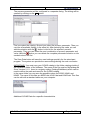
In order to start the conversion operation, click on the <OFFLINE> button. After
the converter has received all values from the part program, the following dialog
will be opened:
In this dialog you can set your additional Q-DAS data. All values, which you set
here, will be used for all characteristics.
Also you can mark your part as an reworked part in this dialog. This setting is
only important if you like to use the setting “Depending on the result, use different
subfolders”. Otherwise you can ignore this setting.
Tipp:
PC-DMIS – Q-DAS Converter Version 2.3.x
Page 16 of 23
User Manual
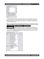
The process parameter will be configured in a separate dialog. The dialog will be
opened by clicking on the ... button.
First you select the catalog. Second you select the process parameter. Then you
can see all available Values in the value list. After selecting the value you can
add the selection with the
button in the list for the selected process
parameter. Then you can select the next combination of process parameter and
value. With the
button you can delete the complete parameter selection or the
marked value in the list.
The Save Data button will save the used settings specially for the actual part
program. The system can provide the same settings during the next conversion.
IMPORTAND: You must copy your Q-DAS catalog in the folder catalogs inside of
the installation folder of the software. The name of the file must be MyCatalog.dfd
Since Version 2.1.2. there is a registry setting (CatalogPathName) which can be
used to define the path and name for the Q-DAS catalog.
In the same folder you can save the possible values for K2320, K2401 and
K2402. The name of this files are K2320.dat, K2401.dat and K2402.dat. This files
can be edit with a standard editor on your computer.
Additional Q-DAS Data for a specific characteristics
PC-DMIS – Q-DAS Converter Version 2.3.x
Page 17 of 23
User Manual
In the PC-DMIS Data frame all imported values are now displayed. The actual
displayed value can be selected in the list box. After the import process all check
boxes in this list are active. This should be also if you export the values later in
the Q-DAS ASCII format.
Before you export the Data in the Q-DAS ASCII format, you can figure out, which
values are inside of the tolerance and which not. For this you can use the buttons
Uncheck all Values , Check OOT Values , Check all Values and
Check OK Values. With the button Add. Data for actual Characteristic you can
add Events for the actual characteristic. Also you can decide, if this characteristic
is a control item (K2006). The used catalog is only a filter for the list. If you add
an event to an individual characteristic, this characteristic will be set to the main
catalog in the Q-DAS ASCII file.
PC-DMIS – Q-DAS Converter Version 2.3.x
Page 18 of 23
User Manual
Before you finally export the Q-DAS data, you have to use the Check all Values
button. Since Version 2.1.2. this will be done automatically.
Now you can export the Q-DAS ASCII data with the ASCII Export button.
3.7. ONLINE conversion
If you like to use the Online functionality of the converter, you need to start the
converter before you execute the part program but after you have opened the
part program.
The Input dialog for Q-DAS data can be closed during runtime of your part
program.
During runtime of the part program the converter receive the Values from PCDMIS.
This process save a lot off time, which is needed, if you receive the values
Offline.
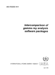
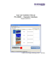
3.8. Execute the converter from the PC-DMIS part program
In order to perform the conversion ONLINE, add an external command in the top
of your part program.
PC-DMIS™ dialogs for external commands
PC-DMIS – Q-DAS Converter Version 2.3.x
Page 19 of 23
User Manual
The complete command is as follows:
EXTERNALCOMMAND/NO_DISPLAY, NO_WAIT ; C:\PROGRAMME\PC-DMIS - Q-DAS
CONVERTER\PCDQDAS.EXE /A
Parameter “/A“ causes conversion to be launched automatically.
Parameter “/I” can be used on Inline systems, where no operator input should be
possible.
Using option “No Display” and “No Wait” to configure the system in the best way.
If you insert this command at the end of the part program (without the parameter
“/A” or “/I”) you can pop up the converter without starting the import functionality.
Then the operator can use the Offline functionality.
A second parameter can be set. This overwrites the adjusted goal listing for the
Q-DAS® ASCII files.
Example:
You like to send the data from this part program to the C:\QDAS_DATA folder.
The complete command is as follows:
EXTERNALCOMMAND/NO_DISPLAY, NO_WAIT ; C:\PROGRAMME\PC-DMIS - Q-DAS
CONVERTER\PCDQDAS.EXE /A /C:\QDAS_DATA
Always use for the separation of the command line arguments one "/". Do not use
blanks in the path designation.
PC-DMIS – Q-DAS Converter Version 2.3.x
Page 20 of 23
User Manual
3.9. List of supported Q-DAS K fields
Key
K0001
K0002
K0004
K0005
K0006
K0007
K0008
K0009
K0010
K0011
K0012
K0053
K0100
K1001
K1002
K1004
K1007
K1010
K1011
K1021
K1022
K1031
K1032
K1041
K1042
K1052
K1053
K1101
K1203
K1209
K1303
K1900
K2001
K2002
K2005
K2006
K2008
K2022
K2030
K2031
K2060
K2061
K2101
K2110
K2111
K2112
K2113
K2120
K2121
Field
Measured value
Attribute
Time
Event
Batch number
Cavity number
Operator name
Text
Machine number
Process parameter
Gage number
Order
Total no. of characteristics in file
Part number
Part description
Part amendment status
Abbreviation part number
Control item
Variant
Manufacturer No.
Manufacturer name
Material number
Material description
Drawing number
Drawing Amendment
Contractor Name
Contract
Department
Reason for test
Inspection type
Plant
Remark (automatically used)
Characteristic number
Characteristic description
Characteristics class
Control item
Characteristics group type
Decimal places
Group number
Group element number
Events catalog
Process parameter catalog
Nominal value
Lower specification limit
Upper specification limit
Lower allowance
Upper allowance
Lower natural boundary
Upper natural boundary
PC-DMIS – Q-DAS Converter Version 2.3.x
Page 21 of 23
User Manual
Key
K2142
K2320
K2401
K2402
K2404
K2900
Field
Unit
Contract number
Gage number
Gage description
Gage Resolution
Remark
Total number of K fields: 55
PC-DMIS – Q-DAS Converter Version 2.3.x
Page 22 of 23
User Manual
3.10.
List of supported dimension types in PC-DMIS™
DIMENSION_A_LOCATION
DIMENSION_D_LOCATION
DIMENSION_FLATNESS_LOCATION
DIMENSION_H_LOCATION
DIMENSION_L_LOCATION
DIMENSION_PA_LOCATION
DIMENSION_PD_LOCATION
DIMENSION_PR_LOCATION
DIMENSION_R_LOCATION
DIMENSION_ROUNDNESS_LOCATION
DIMENSION_RS_LOCATION
DIMENSION_RT_LOCATION
DIMENSION_S_LOCATION
DIMENSION_STRAIGHTNESS_LOCATION
DIMENSION_T_LOCATION
DIMENSION_X_LOCATION
DIMENSION_Y_LOCATION
DIMENSION_Z_LOCATION
DIMENSION_TRUE_DIAM_LOCATION
DIMENSION_TRUE_D1_LOCATION
DIMENSION_TRUE_D2_LOCATION
DIMENSION_TRUE_D3_LOCATION
DIMENSION_TRUE_DD_LOCATION
DIMENSION_TRUE_DF_LOCATION
DIMENSION_TRUE_FLATNESS_LOCATION
DIMENSION_TRUE_LD_LOCATION
DIMENSION_TRUE_LF_LOCATION
DIMENSION_TRUE_PA_LOCATION
DIMENSION_TRUE_PR_LOCATION
DIMENSION_TRUE_ROUNDNESS_LOCATION
DIMENSION_TRUE_STRAIGHTNESS_LOCATION
DIMENSION_TRUE_WD_LOCATION
DIMENSION_TRUE_WF_LOCATION
DIMENSION_TRUE_X_LOCATION
DIMENSION_TRUE_Y_LOCATION
DIMENSION_TRUE_Z_LOCATION
DIMENSION_2D_ANGLE
DIMENSION_2D_DISTANCE
DIMENSION_3D_ANGLE
DIMENSION_3D_DISTANCE
DIMENSION_ANGULARITY
DIMENSION_COAXIALITY
DIMENSION_CONCENTRICITY
DIMENSION_FLATNESS
DIMENSION_KEYIN
DIMENSION_PARALLELISM
DIMENSION_PERPENDICULARITY
DIMENSION_PROFILE
DIMENSION_ROUNDNESS
DIMENSION_RUNOUT
DIMENSION_STRAIGHTNESS
DIMENSION_SYMMETRY
PC-DMIS – Q-DAS Converter Version 2.3.x
Page 23 of 23