1
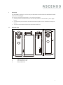
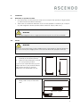
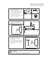
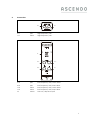
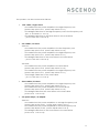
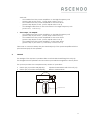
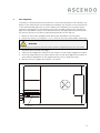
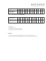
SYSTEM F
USER’S MANUAL
Inhalt
1.
Overview ............................................................................................................................... 3
1.1 General View ....................................................................................................................... 3
1.2 Application ........................................................................................................................... 4
1.3 Safety Warning .................................................................................................................... 4
1.4 Operating modes ............................................................................................................... 4
1.5 Technical Data .................................................................................................................... 5
2. Installation .................................................................................................................................. 6
2.1 Demands on speaker location......................................................................................... 6
2.2 Set-Up .................................................................................................................................... 6
3 Transport ..................................................................................................................................... 8
4. Connection ................................................................................................................................ 9
5. TOS-Unit ..................................................................................................................................... 11
6. Time Alignment ....................................................................................................................... 12
7. Cleaning ................................................................................................................................... 13
ASCENDO GMBH
HÖLDERLINWEG 6
73257 KÖNGEN
GERMANY
Phone:
Fax:
0049 (0) 7024 9288 84
0049 (0) 7024 9288 64
MAIL:
[email protected]
www.ascendo.de
2
1.
Overview
The ASCENDO System F is a four-way Loudspeaker constructed with ASCENDO's SASB
and TOS Technologies.
The strictly modular design leads to several advantages.
perfect phase reconstruction at the actual position of the listener by time alignment.
·
consequently mechanical and electrical decoupled: more details and transparency.
·
very low resonance between loudspeaker and floor.
General View
1
118
2
8,3
111
1.1
·
29
1
High Frequency Unit
2
Low Frequency Unit
3
Base (optional)
3
44
3
1.2
Application
The ASCENDO Loudspeaker System F is intended for use in small to mid-size rooms (<
100 m³).
You can use the System F with amplifiers in the power range of 10 W to 370 W.
1.3
Safety Warning
Warning
This Loudspeaker can produce high sound-levels. This may damage your ears permanently!
1.4
Operating modes
You can use the System F in a single-amp setup (one power amplifier for high- and
low-frequency unit) or in a bi-amp setup (one power amplifier for the low-frequencyunit, one for the high-frequency unit) or in a tri-amp setup (one power amplifier for
the low-frequency-chassis, one for the middle-frequency chassis, one for the highfrequency unit). You even have the possibility to use a tri-a,ping method. Then cable
each of the three stereo amplifiers directly with tweeter, mid and low frequency drier
If your setup is single-amping you must bridge the high- and low-frequency unit with
a high quality speaker cable. If you use bi-wiring you must bridge high- and mid driver accordingly.
The quality of the speakercables and bridges matters: please use high grade cabling
for best sonic performance.
4
1.5
Technical Data
Principle
Four Way SASB-Technology (TOS active)
Three Way SASB-Technology (TOS off)
Dimensions (W/H/D)
29 / 109 / 44 cm, with base 29 / 116 / 44 cm
Weight
48 kg
Power
370 Watt Programm (Min.)
Impedance
6 Ohm
Sensivity
88 dB/1W/m
Frequency Response
31 Hz (-3dB) – 34 kHz
High Frequency Unit
28 mm textile dome tweeter, SD-Caps
Mid Frequency Unit
18 cm woofer with NRSC membrane
Inner Driver
22,5 cm woofer with NRSC membrane
TOS Driver
magneto-static tweeter
TOS Unit
switch-able (TOS driver – dipole On/Off)
Terminals
Si / Bi / Tri-Wiring
Finish
piano lacquering black, rosewood
Manufacturer Warranty
10 years
System F Base
Dimensions (W/H/D)
29 / 6,3 / 44 cm (without spikes)
Weight
8 kg
Finish
piano lacquer black, rosewood
Manufacturer Warranty
10 years
Technical data subject to change
5
2.
Installation
2.1
Demands on speaker location
·
Use the System F in closed rooms only. Do not expose the speaker to high humidity, direct water and direct sunbeam.
·
Take care of a minimum distance of 2 m of the speaker to monitors (TV, computer) and magnetic devices (audio/video-cassettes, floppy-disks, etc.).
WARNING
The speaker might produce a slight permanent imprint on soft floor material!
2.2
Set-Up
WARNING
Don’t try to set-up System F with a single person. The weight of the low frequency
unit is too heavy for a single person. You need at least two people for set-up!
1.
Place the low-frequency unit (2)
carefully at the desired place.
2.
Adjust the low-frequency unit (2)
for your specific position.
If you use the optional base (3), then
adjust this first to your preferred listening position and set-up the lowfrequency unit afterwards on top.
3.
Move the Nut-Stone (4) inside the
rail (5) until it stops to the back
side.
(4) nut-stone (4) rail
6
4.
Place the high-frequency module
(1) carefully on top of the lowfrequency module(2)
5.
Adjust the high-frequency module (1) in flush with the back of
the low-frequency module.
The four feet of the highfrequency module (6) should also
in flush with the edges.
6.
(6)
Insert the long fixing screw (7) into
the hole of the high-frequency
unit (8) and the thread of the nutstone(4)
(7)fixing screw
(8) hole
7.
Tighten the screw (7) carefully
with the allen wrench (9).
8.
Adjust the time alignment (s.
Chapter 6)
9.
Connect the high-frequency unit,
the outer-driver and the innerdriver to your power amplifier (s.
Chapter 4)
(9)allen wrench
close
open
(7)fixing screw
WARNING
Never lift or carry the System F on the high frequency unit!
7
3
Transport
WARNING
Don’t try to move or transport the System F! The weight affords at least two persons!
1. Switch off the power amplifiers and disconnect all cables of the
System F.
2. Pull off the high-frequency (1) unit from the low-frequency unit (3). Lay it on a soft
dry cloth. Take care not to touch the diaphragm of the tweeter.
3. Lift the low-frequency unit from the stand and the upper back-spike. Take care
not to touch the diaphragm of the woofer.
4. Place the low-frequency unit (3) at its new position.
8
4.
Connection
10.1
10.1
plus
high-frequency unit
11.1
minus
high-frequency unit
11.1
12
10.2
11.2
10.3
11.1
10.2
plus
low-frequency unit/ outer driver
10.3
plus
low-frequency unit/ inner driver
11.2
minus
low-frequency unit/ outer driver
11.3
minus
low-frequency unit/ inner driver
12
switch
TOS-unit / dipole On/Off
9
The speaker can be connected as follows:
·
One cable / single-wired:
-
One cable from the power amplifier to the high-frequency unit
(power amp plus to10.1, power amp minus to11.1)
-
One bridge cable from to the high-frequency unit to low-frequency unit
(10.1 to 10.3 and 11.1 to11.3)
One bridge cable from to the inner driver to the outer driver
( 10.2 to 10.3 and 11.2 to11.3)
-
·
Two cables / bi-wired:
Version1:
-
One cable from the power amplifier to the low-frequency unit
(power amp plus to10.3, power amp minus to11.3)
-
One cable from the power amplifier to the high-frequency unit
(power amp plus to10.1, power amp minus to11.1)
-
One bridge cable from to the outer driver to the inner driver
( 10.2 to 10.3 and 11.2 to11.3)
Version2:
·
-
One cable from the power amplifier to the inner driver
(power amp plus to10.3, power amp minus to11.3)
-
One cable from the power amplifier to the high-frequency unit
(power amp plus to10.1, power amp minus to11.1)
-
One bridge cable from to the outer driver
( 10.1 to 10.2 and 11.1 to11.2)
Three cables/ tri-wired:
-
·
One cable from the power amplifier to the high-frequency unit
(power amp plus to10.1, power amp minus to11.1)
One cable from the power amplifier to the outer drivver
(power amp plus to10.2, power amp minus to11.2)
One bridge cable from the outer driver to the inner driver
(10.2 to10.3, 11.2 to11.3)
Two power amps / bi-amped:
Version1:
-
One cable from the power amplifier A to the high-frequency unit
(power amp A plus to10.1, power amp A minus to11.1)
One cable from the power amplifier B to the low-frequency unit
(power amp B plus to10.3, power amp B minus to11.3)
One bridge cable from to the outer driver to the inner driver
(10.2 to10.3, 11.2 to11.3)
10
Version2:
-
·
One cable from the power amplifier A to the high-frequency unit
(power amp A plus to10.1, power amp A minus to11.1)
One cable from the power amplifier B to the inner driver
(power amp B plus to10.3, power amp B minus to11.3)
One bridge cable from to the outer driver to the high frequency unit
(10.2 to10.1, 11.2 to11.1)
Three amps / tri-amped:
-
One cable from the power amplifier A to the high-frequency unit
(power amp A plus to10.1, power amp A minus to11.1)
One cable from the power amplifier B to the outer driver
(power amp B plus to10.2, power amp B minus to11.2)
One cable from the power amplifier C to the inner driver
(power amp C plus to10.3, power amp C minus to11.3)
Take care to connect always the plus terminal (red) of the power amplifier with the
plus terminal (red) of the speaker!
5.
TOS-Unit
The design of the System F speaker utilizes a switch-able back firing TOS-Unit (13)
This integrated unit optimizes and smoothens spectral inhomogeneous decay times.
The system provides two complementary modes of operation:
·
Switch (12) in position AN (dipole):
Dipole characteristic with TOS unit (13)
·
Switch (12) in position AUS (dipole):
BASYC characteristic
(13) TOS unit
11
6.
Time Alignment
To achieve a perfect phase reconstruction, at the actual position of the listener, the
delays of the transducers must be adjusted carefully. The position of the tweeter has
to be mechanically adjusted, so that a plane wave will leave the speaker system
exactly in the direction to the listener's ear. This is possible owing to the specific design of the ASCENDO Systems. The displacement of the high frequency Unit ensures
the correct phase in over-floor positions between 80 cm and 150 cm.
1. Switch off the power amplifiers and disconnect all cables of the System F
2. Unbolt the screw (7) for approx. ca. 1.5 rounds. Use the packed allen wrench(9).
WARNING
By applying too many rounds the screw unlocks completely from the nut-stone!
3. Measure the over-floor ear height.
4. Take the time alignment value from the chart 1/ chart 2 (Time-Alignment-Value).
5. Move the high-frequency until the back side is at the time-alignment position of
the scale(13). Slightly lift up the high-frequency unit (1) while moving it.
6. Bolt the screw (1) again with approx. 1.5 rounds.
(13)Scale
12
Ear height (Ohr)
in cm
80
85
90
95
100
105
110
115
120
125
130
135
140
145
150
Time-AlignmentValue/Scale (13)
without base
5.7
6.0
6.4
6.7
7.0
7.4
7.7
8.1
8.4
8.7
9.1
9.4
9.7
10.1
10.4
Table 1: Time-Alignment-Value without base
Ear height (Ohr)
in cm
80
85
90
95
100
105
110
115
120
125
130
135
140
145
150
Time-AlignmentValue/Scale (13) with
base
5.2
5.5
5.9
6.2
6.6
6.9
7.2
7.6
7.9
8.3
8.6
8.9
9.3
9.6
10.0
Table 2: Time-Alignment-Value with base
Presumptions:
1. Coplanar Set-up
2. Adjustment to the listening position
3. Zero-phase of the electronic chain
7.
Cleaning
Clean the enclosure of the ASCENDO System F with a dry and soft cloth.
Don’t use water or other chemicals. Don’t touch the tweeter and the woofer.
13