1
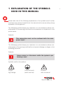
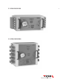
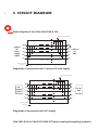
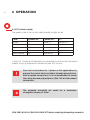
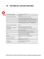
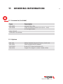
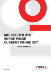
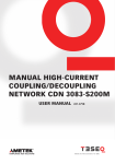
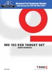
1
CDN 3083-B100 &
CDN 3083-B200 EFT /
BURST COUPLING /
DECOUPLING NETWORKS
USER MANUAL
601-336C
CDN 3083-B100 &
CDN 3083-B200 EFT /
BURST COUPLING /
DECOUPLING NETWORKS
USER MANUAL
CDN 3083-B100 & CDN 3083-B200 EFT/burst coupling/decoupling networks
CONTENTS
1
Explanation of the symbols used in this manual 5
2
Safety advice
6
2.1 Safety measures
7
3Introduction
8
4Installation
10
4.1 Installation of an EUT power switch
10
4.2 Leakage current
11
4.3 EUT supply protection
11
5
Circuit diagram
12
6Operation
14
6.1 EUT power supply
14
6.1.1 Earth connection
15
6.2 Test rig
15
6.3 Operation of the instruments
16
7Accessories
17
7.1 Connectors for reduced current application INA 163 (max. 32 A) (optional)17
7.2 Pulse measurement adapter INA 3243 (optional)
17
7.3 Burst / EFT Pulse Verification Kit CAS 3025 (optional)
18
7.4 Isolated allen Key INA 3005 (included)
18
7.5 EFT cable INA 3008 (included)
19
7.6 Single SHV plug INA 6546 (optional)
19
8Maintenance
20
9Warranty
21
10 Technical specifications 22
11 Ordering information
23
11.1 Accessories (included)
23
11.2Options
23
12 Declaration of conformity (CE)
24
13Addresses
26
1 EXPLANATION OF THE SYMBOLS
USED IN THIS MANUAL
Please take note of the following explanations of the symbols used in order
toachievetheoptimumbenefitfromthismanualandtoensuresafetyduring
operation of the equipment.
The following symbol draws your attention to a circumstance where nonobservation of the warning could lead to inconvenience or impairment in the
performance.
Example:
This connection must not be confused with the main
power input!
The following symbol draws your attention to a circumstance where nonobservation of the warning could lead to component damage or danger to the
operating personnel.
Example:
Never connect or disconnect while the system is performing a test!
Symbols used on the product:
Danger
high voltage
Protective earth
(earth terminal)
Attention
refer to manual
5
6
2 SAFETY ADVICE
ThecouplingdecouplingnetworksCDN3083-B100andCDN3083-B200are
intended for use with burst generators like Teseq’s NSG 3025, NSG 2025,
Modula, NSG 3040 and NSG 3060 series. These CDNs handle high voltage test
pulses and AC / DC EUT supply voltages.
Improper or careless handling can be fatal!
Switch off EUT power supply before starting any manipulations on the screw terminals!
These operating instructions form an integral part of the equipment and must
be available to the operating personnel at all times. All the safety instructions
and advice notes are to be observed.
Keepingresponsibilitytotheinstructionsandrecommendationsthatfollowis
imperative.
The safety advice referring to the generator also applies when using the instrumentstogetherwiththeCDN3083-B100&B200.
Neither Teseq AG, Switzerland nor any of the associated sales organisations accept
any responsibility for personal injury or for material or consequential damage that
may result from irresponsible or negligent operation of this equipment.
The coupling devices are built in conformity with the IEC 61010-1:2001 safety
standard and provide all the amenities for safe and reliable operation.
CDN 3083-B100 & CDN 3083-B200 EFT/burst coupling/decoupling networks
2.1 Safety measures
These operating instructions form an integral part of the instrument and must
be studied carefully before putting the device into use. They must be available
at all times to the operating personnel.
The instrument must only be used by trained personnel.
Persons fitted with a heart pacemaker must not operate the instrument and
should not be in the vicinity of the test rig when pulses are triggered.
Arrange the working area in compliance with appropriate safety standards.
Connect the additional earth plug on the mains supply
input side first!
The test rig must provide adequate insulation protection up to max. pulse voltage
level of the generator (up to 8.8 kV). Particular care should be given to the connections between the CDN 3083-B100 & 200 and the equipment under test (EUT).
The pulse voltage must not be able to find its way to unearthed metal objects
in the event of the EUT failing.
Never leave the instrument unattended when it is connected.
Do not open the instrument.
Long term and high-current tests need to be kept under observation.
The displayed temperature on the CDN 3083-B100 & 200
must not exceed 70°C.
However the temperature at the screwed terminals may
be higher, this as a result of contact resistance between
cable and terminal.
7
8
3INTRODUCTION
High frequency pulse signals can result in cross-talk between conductors
running in parallel even over short distances. This behaviour is taken into
account in the latest and currently valid edition of the EFT / burst standard
EN / IEC 61000-4-4 (2012).
Only the single coupling mode of «all conductors together against reference
ground» is called for in interference immunity testing with fast transients. The
units allow for test pulses of up to 8.8 kV.
The CDN 3083-B100 and the CDN 3083-B200 are designed to be used with an
EUT supply in AC mode up to 690 V (line to line). DC voltage can be taken up
to 1000 VDC.
The CDN 3083-B100 & B200 are 3-phase burst pulse coupling networks for
large EUT currents. Although designed for continuous duty at up to 100 and
200 A per phase, the units can be subjected to considerably higher currents
for short durations.
As a result, high inrush currents or pulse-shaped peak currents can be handled
with ease. The current limitation is largely a matter of thermal loading and
ambient temperature. A built-in thermometer enables the heating effect to be
monitored.
The type of construction, inside a metal housing for use directly on the ground
reference plane, ensures excellent HF earthing. The EUT supply connections
take the form of generously dimensioned screw terminals.
The coupling network CDN 3083-B100 & B200 serves to inject fast transients
(burst) up to 8.8 kV (5 / 50 ns – 50 Ω) into the supply to the device under test.
CDN 3083-B100 & CDN 3083-B200 EFT/burst coupling/decoupling networks
3.1 CDN 3083-B100
3.2 CDN 3083-B200
9
10
4INSTALLATION
The instruments conform to the safety requirements, but with an increased
leakage current given by the decoupling filter.
Operation without a protective earth connection is forbidden!
Operate the equipment only in dry and clean surroundings. Any condensation
that occurs must be allowed to evaporate before putting the equipment into
operation. Do not exceed the permissible ambient temperature or humidity
given in the IEC specification.
Only handle the test rig or the device being tested when
the EUT power supply is switched off and the generator‘s
test sequence has been halted or aborted.
4.1 Installation of an EUT power switch
It is recommended to connect the CDN 3083-B100 & B200 through a properly
rated power switch device, which should be located close to the test setup. In
order to ensure an easy and quick acces to the EUT power, the switch should
be clearly and visibly labelled as a device for «EUT power on / off» switching.
The inhouse power distribution needs to be equipped with a proper circuit
breaker and an emergency off button as per IEC 61010-1.
CDN 3083-B100 & CDN 3083-B200 EFT/burst coupling/decoupling networks
The test setup should only be accessible to trained
persons.
4.2 Leakage current
Local installation regulations must be respected to ensure the safe flow of
leakage currents.
Use only nationally approved connectors and accessory items.
Ensure that a reliable return path for the interference current is provided
between the EUT and the coupling network. The reference ground plane and
the earth connections to the instruments as described in the relevant test
standards serve this purpose well.
4.3 EUT supply protection
Dimensioning of EUT supply and rating of fuse protection (AC or DC), must
conform with National prescriptions and EUT requirements. An inappropriate
arrangement, mounting, cabling and / or handling of the device under test or
the protective elements can make the protective features that are incorporated
in the concept of the device worthless.
11
12
5 CIRCUIT DIAGRAM
Block diagram of the CDN 3083-B100 & 200
Signal from test generator
Cc
PE'
PE
3-phase
AC
mains
supply
input
Cc
N'
N
Cc
L1'
L1
Cc
L2'
L2
3-phase
to
EUT
Cc
L3'
L3
> 100 µH
Reference ground
connector
Ferrites
Decoupling section
Cc = 33 nF
Coupling section
Diagramm of connection with 3-phase AC main supply
Signal from test generator
Cc
PE'
PE
DC
supply
input
Cc
N'
N
Cc
L1'
L1
DC to
EUT
Cc
L2'
L2
Cc
L3'
L3
> 100 µH
Reference ground
connector
Ferrites
Decoupling section
Cc = 33 nF
Coupling section
Diagramm of connection with DC supply
CDN 3083-B100 & CDN 3083-B200 EFT/burst coupling/decoupling networks
Signal from test generator
13
Cc
1-phase
AC
main
supply
PE'
PE
Cc
N'
N
Cc
L1'
L1
Cc
L2'
L2
Cc
L3'
L3
> 100 µH
Reference ground
connector
Decoupling section
Ferrites
Cc = 33 nF
Coupling section
Diagramm of connection with 1-phase AC main supply
1-phase
to EUT
14
6OPERATION
6.1 EUT power supply
The power is fed in via a 5-core cable usually brought out as:
Color
3-phase AC
1-phase AC*
DC*
brown
L1
phase (L)
positive (+)
black
L2
black
L3
blue
N
neutral (N)
negative (-)
green / yellow
PE
ground (PE)
PE
* Note: For 1-phase or DC application it is possible to use the input channels in
parallel, thus it is possible to increase the max. EUT current.
Care has to be taken for 1-phase or DC application to
prevent the risk of electrical shock through unused channels (screwed connectors). It is recommended to screw
the safety banana plug adapters (INA 163) on the unused
connectors.
The screwed terminals are made for a maximum
strengthen torque of 8 Nm.
CDN 3083-B100 & CDN 3083-B200 EFT/burst coupling/decoupling networks
15
6.1.1 Earth connection
The earth connection lug on the power supply input serves to ensure a good
connection to the protective earth on the test rig.
6.2 Test rig
Every test rig must be planned carefully. All the instrumentation should be
readily accessible and rigidly positioned.
The preceding safety measures are to be observed. The
test object may only be handled when the instruments
and mains are switched off.
The whole test setup should be supplied from the same
mains connection in order to prevent an uncontrolled
flow of pulse current in other parts of the system. Installation in a Faraday cage ensures that non-associated
items and equipment are not disrupted by pulses radiated from the cabling or the device under test. Connections to the EUT must be of low impedance and be made
with high contact pressure otherwise welding or arcing
might occur at the contact points.
AC mains cable
L= 0.5 m
Mains
supply
16
EFT generator
CDN 3083-B100 or B200
EUT
Isolating
support
(10 cm)
Connection to
ground reference plane
Protective earth on
ground reference plane
Ground
reference plane
to protective
ground
Non conductive table
Example of a system configuration with the NSG 3040.
Please refer to IEC 61000-4-4 and respective product standards for the various
test setups.
6.3 Operation of the instruments
It is assumed that the test rig has been set up in accordance with the preceding
notes and that the device to be tested has been connected taking the relevant
safety measures into account.
Only handle the test rig or the device being tested when
the EUT power supply is switched off and the generator‘s
test sequence has been halted or aborted.
It is possible to overstress the CDN 3083-B100 & B200 for a certain time.
However, attention has to be given to the heat control placed on the CDN
3083-B100 or B200.
The displayed temperature on the CDN 3083-B100 & 200
must not exceed 70°C.
However the temperature at the screwed terminals may
be higher, this as a result of contact resistance between
cable and terminal.
CDN 3083-B100 & CDN 3083-B200 EFT/burst coupling/decoupling networks
7ACCESSORIES
7.1 Connectors for reduced current application INA 163
(max. 32 A) (optional)
In case, an EUT needs to be exchanged frequently, the optional safety banana
plug set INA 163 gives the possibility to connect the EUT in an easy and safe way.
With this option the max. current consumption of the EUT must not exceed 32 A.
INA 163 safety banana plug adapter set
7.2 Pulse measurement adapter INA 3243 (optional)
The measurement adapter INA 3241 is necessary to measure the Burst / EFT
pulse at output terminals.
INA 3243 measuring adapter
17
18
The measurement or the verification of the CDN has to
be done with a switched off and disconnected power
supply.
Pulses can then be observed at the output connectors by means of an oscilloscope.
7.3 Burst / EFT Pulse Verification Kit CAS 3025 (optional)
To fulfil the EN / IEC 61000-4-4 standard recommendation, each line needs to
be measured separately, terminated with 50 Ω. For this purpose the terminator / attenuator INA 265A (which is part of the CAS 3025 calibration set) is
recommended.
7.4 Isolated allen Key INA 3005 (included)
CDN 3083-B100 & CDN 3083-B200 EFT/burst coupling/decoupling networks
7.5 EFT Cable INA 3008 (included)
7.6 Single SHV plug INA 6546 (optional)
Single SHV plug for custom made cables to connect with any EFT generator.
19
20
8MAINTENANCE
Maintenance is limited to cleaning and eventually removal of any foreign particles or objects from the contact surfaces since such matter can adversely
affect the test parameters. The housing can be cleaned with a moist cloth with
optionaly just a trace of liquid detergent.
Other solvents are not permitted.
The thermometer can be removed and may be replaced in case of damage. It
can be pulled out of his fixture by hand.
The CDN 3083-B100 & B200 are fully potted, so there are no serviceable parts
internally.
CDN 3083-B100 & CDN 3083-B200 EFT/burst coupling/decoupling networks
9WARRANTY
Teseq grants a warranty of 24 months against material and manufacturing
defects. Excepted from this warranty are damages incurred during transportation, damages caused through use of the equipment for unforeseen purposes
and the effects of excessive physical force.
21
22
10 TECHNICAL SPECIFICATIONS
EUT (supply) voltage:
EUT current (AC or DC): 690 VAC, line-to-line
1000 VDC
≥100 A continuous (for – B100)
and >200 A continuous (for –B200)
The maximum permissible current is given by
the heat dissipated in the coupler. As the temperature is monitored, heavy overloads until
the temperature reaches 70°C are possible.
Burst pulse peak voltage: Terminals:
Temperature monitoring: Grounding:
Size:
Weight:
EFT / burst connector:
Temperatur range:
Humidity:
Air pressure:
8800 V
Screw terminals, rated for 200 A
Bimetal-thermometer 0 to +120° C
4 mm combined banana and screw terminal
(safety grounding).
Via housing bottom plate and brackets
(HF ground to test setup ground-plane)
410 x 170 x 190 mm (-B100)
430 x 310 x 190 mm (-B200)
5 kg (-B100), 11 kg ( - B200) approx.
SHV
Operation at +10 to +40° C
Storage at -10 to +60° C
30 to 78% (non condensing)
860 to 1060 hPa
CDN 3083-B100 & CDN 3083-B200 EFT/burst coupling/decoupling networks
11 ORDERING INFORMATION
11.1 Accessories (included)
TypeDescription
INA 3005
Isolated Allen Key
INA 3008
Coax connection cable 0,8 m (SHV – SHV)
to burst generator
User manual
Calibration certificate
11.2 Options
INA 163
INA 3243 CAS 3025 INA 6546 Safety banana plug set (10 pcs.), 6 to 4 mm
Pulse measurement adapter
Burst / EFT Pulse Verification Kit
Single SHV plug for custom made cables
23
24
12 DECLARATION OF CONFORMITY (CE)
CDN 3083-B100 & CDN 3083-B200 EFT/burst coupling/decoupling networks
25
Headquarters
Teseq AG
4542 Luterbach, Switzerland
T + 41 32 681 40 40
F + 41 32 681 40 48
sales @ teseq.com
www.teseq.com
Manufacturer
Teseq AG
4542 Luterbach, Switzerland
T + 41 32 681 40 40
F + 41 32 681 40 48
sales @ teseq.com
China
Teseq Company Limited
T + 86 10 8460 8080
F + 86 10 8460 8078
chinasales @ teseq.com
France
Teseq Sarl
T + 33 1 39 47 42 21
F + 33 1 39 47 40 92
francesales @ teseq.com
Germany
Teseq GmbH
T + 49 30 5659 8835
F + 49 30 5659 8834
desales @ teseq.com
Japan
Teseq K.K.
T + 81 3 5725 9460
F + 81 3 5725 9461
japansales @t eseq.com
Singapore
Teseq Pte Ltd.
T + 65 6846 2488
F + 65 6841 4282
singaporesales @ teseq.com
Switzerland
Teseq AG
T + 41 32 681 40 50
F + 41 32 681 40 48
sales @ teseq.com
Taiwan
Teseq Ltd.
T + 886 2 2917 8080
F + 886 2 2917 2626
taiwansales @ teseq.com
UK
Teseq Ltd.
T + 44 845 074 0660
F + 44 845 074 0656
uksales @ teseq.com
USA
Teseq Inc.
T + 1 732 417 0501
F + 1 732 417 0511
Toll free +1 888 417 0501
usasales @ teseq.com
© July 2014 Teseq®
Specifications subject to change without
notice. All trademarks recognized. Teseq® is
an ISO-registered company. Its products are
designed and manufactured under the strict
quality and environmental requirements of
the ISO 9001. This document has been careTo find your local partner within fully checked. However, Teseq® does not
Teseq®’s global network, please go to assume any liability for errors, inaccuraciewww.teseq.com
sor changes due to technicaldevelopments.