1
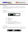
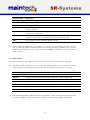
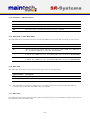
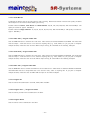
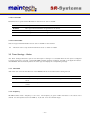
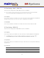
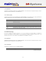
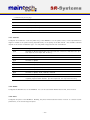
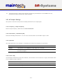
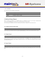
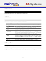
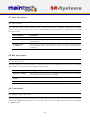
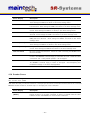
MidiMod Firmware
User’s Manual
Contents
0 Definition
3.2.21 LCN number . . . . . . . . . .
Tuner Settings – Basics . . . . . . . .
3.3.1 TX Enable . . . . . . . . . . .
3.3.2 Frequency . . . . . . . . . . .
3.4 Tuner Settings – DVB-T / DVB-T Div
3.4.1 Frequency . . . . . . . . . . .
3.4.2 Bandwidth . . . . . . . . . . .
3.5 Tuner Settings – DVB-S/-S2 . . . . .
3.5.1 Frequency . . . . . . . . . . .
3.5.2 Symbolrate . . . . . . . . . .
3.5.3 LNC Power . . . . . . . . . .
3.5.4 LNC 22kHz Tone . . . . . . .
3.6 Tuner Settings – DVB-C . . . . . . .
3.6.1 Frequency . . . . . . . . . . .
3.6.2 Symbolrate . . . . . . . . . .
3.6.3 Constellation . . . . . . . . . .
3.7 Modulator Settings . . . . . . . . . .
3.7.1 Mode . . . . . . . . . . . . .
3.7.2 PSI / PSI Settings . . . . . .
3.7.3 BISS / BISS Settings . . . . .
3.8 DVB-S Settings . . . . . . . . . . . .
3.8.1 Symbolrate . . . . . . . . . .
3.8.2 Coderate (FEC) . . . . . . . .
3.9 DVB-S2 Settings . . . . . . . . . . .
3.9.1 Symbolrate . . . . . . . . . .
3.9.2 Constellation . . . . . . . . . .
3.9.3 Coderate . . . . . . . . . . . .
3.9.4 Rolloff . . . . . . . . . . . . .
3.9.5 Pilots . . . . . . . . . . . . .
3.10 DVB-C Settings . . . . . . . . . . . .
3.10.1 Symbolrate . . . . . . . . . .
3.10.2 Constellation . . . . . . . . . .
3.11 DVB-T Settings . . . . . . . . . . . .
3.11.1 Coderate (FEC) . . . . . . . .
3.11.2 Constellation . . . . . . . . . .
4
3.3
1 Frontpanel
1.1 Status Screen . . . . . . . . . . . . . .
1.2 Configuration Menu . . . . . . . . . . .
4
4
5
2 Controlling the MidiMod via the RS232
2.1 Establishing a Connection . . . . . . . .
2.2 Changing Settings . . . . . . . . . . . .
5
5
6
3 Menu Structure
3.1 IN x / Input Settings . . . . . . . . . .
3.1.1 Mode / Input Mode . . . . . . .
3.1.2 PSI Tables . . . . . . . . . . . .
3.2 Encoder / Encoder Settings . . . . . . .
3.2.1 System Bitrate . . . . . . . . .
3.2.2 Video Input . . . . . . . . . . .
3.2.3 Video Format . . . . . . . . . .
3.2.4 Resolution / Video Resolution .
3.2.5 GOP Mode / Video GOP Mode
3.2.6 Video AGC . . . . . . . . . . . .
3.2.7 Video Gain . . . . . . . . . . . .
3.2.8 Audio Input . . . . . . . . . . .
3.2.9 Audio Channel . . . . . . . . . .
3.2.10 Audio Volume . . . . . . . . . .
3.2.11 Audio Mode . . . . . . . . . . .
3.2.12 Samplerate / Audio Samplerate
3.2.13 Audio Bitrate . . . . . . . . . .
3.2.14 Video PID / Program Video PID
3.2.15 Audio PID / Program Audio PID
3.2.16 PMT PID / Program PMT PID
3.2.17 Program ID . . . . . . . . . . .
3.2.18 Program Prov. / Program Provider
3.2.19 Program Name . . . . . . . . .
3.2.20 LCN mode . . . . . . . . . . . .
6
6
6
8
8
8
8
9
10
10
10
10
11
11
11
11
11
12
12
12
12
12
12
12
13
–1–
.
.
.
.
.
.
.
.
.
.
.
.
.
.
.
.
.
.
.
.
.
.
.
.
.
.
.
.
.
.
.
.
.
.
.
13
13
13
13
14
14
14
14
14
14
14
15
15
15
15
15
15
16
16
17
17
18
18
18
18
18
19
19
19
20
20
20
20
20
21
3.11.3 Guard Interval . . . . . . . . . .
3.11.4 Bandwidth . . . . . . . . . . . .
3.12 HF Output Settings . . . . . . . . . . .
3.12.1 Frequency / Output Frequency .
3.12.2 Attenuation / Attenuation (HF)
3.12.3 Spectrum . . . . . . . . . . . .
3.12.4 Carrier Only . . . . . . . . . . .
3.12.5 TX Enable . . . . . . . . . . . .
21
21
22
22
22
22
22
23
4 Verbose Status Report
4.1 Product/Version Information . . . . . .
4.2 Global Status . . . . . . . . . . . . . .
23
23
23
4.3
4.4
4.5
4.6
4.7
4.8
4.9
4.10
4.11
4.12
Input Status . . .
Output Status . .
PSI Status . . . .
TS Input Status .
Input Port Status
ASI Input Status .
Tuner Status . . .
Encoder Status .
System . . . . . .
Modulator Status
5 Status Codes
–2–
.
.
.
.
.
.
.
.
.
.
.
.
.
.
.
.
.
.
.
.
.
.
.
.
.
.
.
.
.
.
.
.
.
.
.
.
.
.
.
.
.
.
.
.
.
.
.
.
.
.
.
.
.
.
.
.
.
.
.
.
.
.
.
.
.
.
.
.
.
.
.
.
.
.
.
.
.
.
.
.
.
.
.
.
.
.
.
.
.
.
.
.
.
.
.
.
.
.
.
.
.
.
.
.
.
.
.
.
.
.
.
.
.
.
.
.
.
.
.
.
23
24
24
24
25
25
25
26
27
27
27
2010-11-18
11:42
The information in this manual was compiled with care and to our best knowledge; nevertheless there are probably
some errors left in this document. We do not take legal or any other responsibility for the correctness of any
information.
We are happy to receive your feedback. If you found an error or think that something should be explained in greater
detail, don’t hesitate to contact us.
This document is protected by copyright law. All trademarks are owned by their respective owners.
maintech GmbH
Otto-Hahn-Straße 15
D-97204 H¨
ochberg
Germany
Phone +49 (931) 40 70 6 90
Fax +49 (931) 40 70 6 53
Web http://www.maintech.de
EMail [email protected]
–3–
0 Definition
The SR-Systems MidiMod is a universal, software defined radio platform suitable for a wide range of modulation
schemes. For professional use, maintech provides firmware for the following modulation standards: DVB-T, DVB-S,
DVB-S2, DVB-C and ATSC. MidiMod uses a direct I/Q modulation approach, which allows for a wide frequency
range while maintaining a low component count.
1 Frontpanel
The MidiMod can be controlled via an optional LCD/keypad unit connected to the frontpanel connector. The
frontpanel consists of a LC Display, several LEDs and buttons.
¶
·
¸
¹
º
»
J
∗
N
ok
H
÷
I
F
Figure 1: Frontpanel display and button arrangement
¶
·
¸
¹
º
»
Power LED
RF Status LED
Encoder / Tuner Status LED
FPGA Status LED
Encoder Status LED
ON-AIR LED
F
ok
N H
J I
∗
÷
Enter and exit the menu, abort data entries
Edit the current menu item and commit the changes
Browse menu categories, change character while editing an item
Browse menu items within a category, move cursor while editing an item
Switch display backlight on and off
Press and hold for several seconds to disable modulator output
1.1 Status Screen
Under normal conditions, the frontpanel display shows the MidiMod status screen. On this screen, the first line
shows the product name, which can be slightly different from the example shown here. The second line shows the
current status code. See the MidiMod Status Codes in section 5 on page 27 for a list of possible messages and their
meaning.
Figure 2: MidiMod status screen without and with error message
–4–
1.2 Configuration Menu
F button enters the configuration menu.
Whenever you see the status screen on the frontpanel display, pushing the N and H buttons. The J and
The menu items are grouped in various categories. To select a category, use the I buttons will browse the items within the selected category. Use the N and H buttons again to select a different
category. See MidiMod Menu Structure on page 6 for a list of all available categories and menu items. Press the
ok button to edit the menu item currently displayed. Press the F button to exit the menu and return to the splash
screen.
Figure 3: Category and menu item selection
ok button, the value can be changed with the J and I buttons. If the
After selecting an item for editing with the J and I buttons move the
item does not represent a distinct set of options but a number or a text string, the N and H change the character under the cursor. Use the ok button to save the changes and press the
cursor and F button to revert the modifications and return to the item selection.
Figure 4: Editing an item with distinct options and a string item
2 Controlling the MidiMod via the RS232
All configuration options that are available on the frontpanel can also be modified via the RS232 interface on the
MidiMod PCB. Please refer to the MidiMod hardware datasheet1 for the pinout.
2.1 Establishing a Connection
The RS232 interface can be used with standard terminal software, e.g. HyperTerminal (included with some versions
of the Windows operating system), Putty2 or any other VT100 compatible terminal software. Set your PC serial port
to 115200 Baud, eight bits per character, no parity, one stopbit (115k2-8N1) and disable any flow control.
When powering up your MidiMod, you should see a boot message similar to this example:
DVB Midimod Firmware V0.2
(c) 2009-2010 maintech GmbH
FPGA firmware v005 successfully uploaded
SI570 XTAL: 114309326 Hz
OnBoard REF: SI570
OnBoard VCO: ADF4350
1
2
REF: 100000000 Hz
MidiMod hardware datasheet: http://www.maintech.de/DS2MO/
Download Putty at http://www.chiark.greenend.org.uk/˜sgtatham/putty/download.html
–5–
OnBoard Gain: I/Q
Real HF output range (on-boad upconverter):
* 68750 - 2300000 kHz
2.2 Changing Settings
After the boot process is complete, the MidiMod displays its main menu, which also can be re-displayed by pressing
Enter in the terminal software.
MidiMod Mainmenu
1) show status
2) HF Output Settings
3) Modulator
4) Input1
5) Input2
> _
The contents of the main menu depend on the connected transport stream source – a tuner will need other settings
than the MPEG2 encoder.
A menu option is selected by entering its number followed by pressing Enter .
3 Menu Structure
3.1 IN x / Input Settings
The options in the Input Settings category tell the MidiMod what kind of device is connected to the TS input
connectors and how the transport stream is configured. For devices like the MPEG2 encoder, it also enables uploading
of the required firmware image.
3.1.1 Mode / Input Mode
This menu item tells the MidiMod what kind of device is connected to the TS input connector.
–6–
Selected Value
Description
MPEG Encoder
The MidiMod will configure and control an SR-Systems MPEG2 encoder module connected to the TS input port
Tuner
The MidiMod will configure and control an SR-Systems tuner module (NIM). Supported
tuner modules are:
• DVB-S tuner (Datasheet: http://www.maintech.de/DSNS1)
• STV0297 DVB-C tuner (Datasheet: http://www.maintech.de/DSNC1)
• DiBcom
3000
DVB-T
tuner
(diversity
or
single)
(Datasheet:
http://www.maintech.de/DSNTD or http://www.maintech.de/DSNT1)
• NXT6000 DVB-T tuner
The MidiMod will also control SR-Systems intelligent tuner modules. Intelligent tuner
modules can be used standalone and be configured via display or serial port. When they
are connected to a MidiMod, the MidiMod will control the tuner module, and the tuner’s
local settings are disabled. Plase note that for this feature the NIM’s firmware version
must be 0.28 or later. Supported intelligent tuner modules are:
• ATSC tuner (Datasheet: http://www.maintech.de/DSIA1)
• DiBcom 7000 (Datasheet: http://www.maintech.de/DSIT1)
• DVB-S/S2 tuner (Datasheet: http://www.maintech.de/DSIS2)
The MidiMod automatically detects the connected tuner type.
ASI
The MidiMod will control an SR-Systems ASI input module (ASI-In) on the TS input
port.
generate clk
A transport stream is expected on the TS input port. The MidiMod will generate the TS
clock with a clock rate configured in the menu item Input x. The data will be latched
on rising clock edge.
• Clockrate: Sets the clock rate. Valid values are between 10 and 100000 kbps.
• PSI Tables: See the section 3.1.2 about PSI Tables on page 8 for the relevant
parameters.
continued on next page...
–7–
...continued from previous page
Selected Value
Description
external clk
A transport stream is expected on the TS input port. The MidiMod will expect a TS
clock from the connected device. The data will be latched on rising clock edge. See the
section 3.1.2 about PSI Tables on page 8 for the relevant parameters. Use this setting
when connecting one of the following devices:
• MiniMux or MidiMux multiplexer
(See the maintech application note http://www.maintech.de/ANCHM for information on how to chain multiplexers.)
• legacy 4-TS multiplexer
3.1.2 PSI Tables
This option is only available when Input Mode is set to Tuner, to ASI, to generate clk or to external clk.
Selected Value
Description
pass
PSI Tables are not blocked.
block
PSI Tables are blocked.
3.2 Encoder / Encoder Settings
The following menu items are subitems of the Input x Settings submenu Encoder. They are only available if the
Input Mode is set to MPEG encoder and an encoder is physically connected.
3.2.1 System Bitrate
Set the encoder’s system bit rate (audio, video and tables) to the given value. The modulator does not check if your
configured system bitrate fits into the bandwidth provided by the configured modulation settings. The user has to
make sure that the system bitrate is at least 3% below the modulation bitrate. Please enter a bitrate value based
on 188-byte-packets in kBit/s with possible values between 1000 kBit/s and 20000 kBit/s. If the given value is too
low, the encoding process will stop at the first buffer overflow.
3.2.2 Video Input
This selects the used hardware input for the video signal.
–8–
Selected Value
Description
disabled
Do not encode a video signal. The stream will be announced as radio service.
CVBS
Encode signal from the encoder’s CVBS input.
YC
Encode signal from the encoder’s Y/C (S-Video) input.
YCbCr
Encode YCbCr signal from the encoder’s external video connector. Pin 10 is Y, pin 12
is Cb, Pin 14 is Cr.
RGB
Encode RGB video signal from the encoder’s external video connector. Pin 10 is green,
pin 12 is blue, pin 14 is red.
SCART
Encode RGBS (RGB with external sync) video signal from the encoder’s external video
connector. Pin 8 is sync, pin 10 is green, pin 12 is blue, pin 14 is red.
SDI
Encode signal from the attachable SDI input board.
+ YCbCr, RGB and SCART are only available if a newer encoder board with TVP video decoderchip is connected. Older encoders with SAA video decoder only support CVBS and Y/C. See the
MPEG encoder datasheet at http://www.maintech.de/DSENC for information about the external
video connector.
3.2.3 Video Format
The Video Format menu item configures the encoder to the format that is used on the input signal.
+ The Video Format configuration is not available when SDI is selected on an encoder with a new SDI
input extension board. The SDI extension board will autodetect the video format in that case.
Selected Value
Description
PAL
Standard PAL television signal
PAL-60
The video signal is interpreted as PAL-60 (PAL with 60 Hz and 525 lines)
PAL-M-60
The video signal is interpreted as PAL-M (PAL with 60 Hz and 525 lines)
PAL-N
The video signal is interpreted as PAL-60 (PAL with 60 Hz and 525 lines)
NTSC
The video signal is interpreted as NTSC
NTSC-4.43
NTSC with color carrier at 4.43 MHz
SECAM
The video signal is interpreted as SECAM
+ PAL-60, PAL-M, PAL-N and NTSC-4.43 are only available if a newer encoder with TVP video decoder
is connected. Older encoders with SAA video decoder only support PAL, NTSC and SECAM.
–9–
3.2.4 Resolution / Video Resolution
Selected Value
Description
D1
The video image is encoded with full resolution: 720x576
HD1
The video image is encoded with half resolution: 360x576
CIF
The video image is encoded with quarter resolution: 360x288
3.2.5 GOP Mode / Video GOP Mode
The GOP Mode menu item defines how the encoder uses different frame types while encoding the video stream.
Selected Value
Description
I
Each GOP consists only of I-frames
IP
The encoder uses one I-frame and then only P-frames inside a GOP. For a GOP size of
ten, the resulting GOP will look like this: IPPPPPPPPP.
IBP
The encoder uses an I-frame at the beginning of the GOP and encodes the rest in B and
P frames. For a GOP size of ten, the resulting GOP will look like this: IBPBPBPBPB.
IBBP
The encoder uses an I-frame at the beginning of each GOP and encodes the rest in B and
P frames. For a GOP size of ten, the resulting GOP will look like this: IBBPBBPBBP.
3.2.6 Video AGC
The Video AGC menu item controls the automatic gain control of the video input.
Selected Value
Description
disabled
The video gain is set manually using the Video Gain setting.
enabled
The automatic gain control of the video input is active.
+ The video AGC and video gain settings are not available for older encoders with SAA video ADC. If
the input is set to SDI, the video AGC is also not available.
3.2.7 Video Gain
The Video Gain menu item controls the video gain if the automatic gain control is disabled. Possible values are from
0 to 300 where 148 is the default value.
– 10 –
3.2.8 Audio Input
This menu item decides if audio is encoded and transmitted. For video-only mode, set this to disabled.
Selected Value
Description
disabled
No audio data is encoded and transmitted.
analog
Audio is encoded from the encoder’s analog inputs.
SDI
Audio is extracted and encoded from the attached SDI input port.
3.2.9 Audio Channel
This menu item selects the audio channels for de-embedding from SDI. It is only available when a SDI input module
with support for embedded audio is connected to the TS input port.
Possible values are: 1.12, 1.34, 2.12, 2.34, 3.12, 3.34, 4.12 and 4.34.
3.2.10 Audio Volume
The Audio Volume menu item lets the user attenuate the received SDI audio signal before encoding. It is only
available when a SDI input module with support for embedded audio is connected to the TS input port. Possible
values are in the range 0 dB to -60 dB.
3.2.11 Audio Mode
Configures the audio channel mode for the encoded audio data.
Selected Value
Description
Stereo
The audio from the left and right input is encoded as stereo signal.
Joint Stereo
Stereo encoding with better quality but less stereo channel separation.
Dual Channel
The signal from the left and right input is encoded as two separate mono channels.
Single Channel
The audio is encoded as single mono channel.
3.2.12 Samplerate / Audio Samplerate
Configures the sample rate for analog audio input.
Possible values are: 32 kHz, 44.1 kHz, 48 kHz.
– 11 –
3.2.13 Audio Bitrate
Configures the bitrate that the encoder uses for audio encoding. More bitrate results in better audio quality. Possible
values depend on the selected Audio Mode (see 3.2.11).
Possible values for Stereo, Joint Stereo and Dual Channel: 64, 96, 112, 128, 160, 192, 224 and 256 kBit/s. CD
quality is reached at approx. 224 kBit/s.
Possible values for Single Channel: 32, 48, 56, 64, 80, 96, 112, 128, 160 and 192 kBit/s. CD quality is reached at
approx. 160 kBit/s.
3.2.14 Video PID / Program Video PID
Sets the DVB PID used to transmit the video data. Valid values are between 0x0020 and 0x1FFE. The video PID
must be unique – make sure that it is not used for anything else (e.g. audio, PMT, etc.) If you plan to multiplex
multiple streams, make sure that the video PID is unique among all other PIDs in the resulting multiplex.
3.2.15 Audio PID / Program Audio PID
Sets the DVB PID used to transmit the audio data. Valid values are between 0x0020 and 0x1FFE. The audio PID
must be unique – make sure that it is not used for anything else (e.g. video, PMT, etc.) If you plan to multiplex
multiple streams, make sure that the audio PID is unique among all other PIDs in the resulting multiplex.
3.2.16 PMT PID / Program PMT PID
Sets the DVB PID used to transmit the PMT for the encoded service. Valid values are between 0x0020 and 0x1FFE.
The PMT PID must be a unique PID that is not used for video, audio or anything else. If you plan to multiplex
multiple streams, make sure that the PMT PID is unique in the whole multiplex.
3.2.17 Program ID
Sets the service ID transmitted in the PAT, PMT, NIT and SDT.
3.2.18 Program Prov. / Program Provider
Sets the service provider name transmitted in the SDT.
3.2.19 Program Name
Sets the service name transmitted in the SDT.
– 12 –
3.2.20 LCN mode
Determines if a Logical Channel Number for this service is sent in the NIT.
Selected Value
Description
disabled
No Logical Channel Number is signalled for the service.
visible
The Logical Channel Number is signalled as visible channel.
hidden
The Logical Channel Number is signalled as hidden command.
3.2.21 LCN number
Sets the Logical Channel Number that is sent in the NIT for this channel.
+ This menu item is only shown if LCN mode is set to visible or hidden.
3.3 Tuner Settings – Basics
The Tuner Settings submenu is part of the menu Input x Settings. It is available when the TS input is configured
to Tuner mode (see 3.1.1) and a compatible NIM (network interface module) is attached to the physical interface.
The MidiMod will automatically detect the tuner type and display the corresponding settings.
3.3.1 TX Enable
This menu item controls the behaviour of the MidiMod when the attached tuner loses signal lock.
Selected Value
Description
Always
The MidiMod always transmits – even when no valid signal is received by the attached
tuner.
On Tuner Lock
The MidiMod only starts transmission when the attached tuner is locked to a valid
carrier.
3.3.2 Frequency
All NIM modules need a frequency to tune onto. The frequency is given in kHz and refers to the center of the
channel. See the specific sections for DVB-T, -S/S2 and -C for the allowed ranges.
– 13 –
3.4 Tuner Settings – DVB-T / DVB-T Div
These menu items are displayed when a DVB-T NIM is attached to the MidiMod.
+ FEC, constellation setting and guard interval are automatically detected from the TPS bits embedded
into the carrier. Only frequency and bandwidth need to be set to receive a signal.
3.4.1 Frequency
Set the reception frequency for the DVB-T tuner in kHz. Valid values are between 145000 kHz and 858000 kHz.
The DVB-T frequency refers to the center of the channel – independently of the bandwidth.
3.4.2 Bandwidth
Set the reception bandwidth for the DVB-T tuner in MHz. Valid values are between 1 MHz and 8 MHz.
3.5 Tuner Settings – DVB-S/-S2
These menu items are displayed when a DVB-S NIM is attached to the MidiMod.
3.5.1 Frequency
Set the reception frequency for the DVB-S tuner in kHz. Valid values are between 950000 kHz and 2150000 kHz.
+ The MidiMod does not account for the LOF of an LNB that you might use. If you use an LNB to
receive the DVB-S signal, you need to calculate the IF and set the frequency to that value.
3.5.2 Symbolrate
Set the reception symbol rate for the DVB-S tuner in kSym/s. Valid values are in the range between 1000 kSym/s
and 45000 ksym/s.
3.5.3 LNC Power
Selected Value
Description
Off
The DVB-S tuner does not supply power to the HF input.
13V
The DVB-S tuner supplies 13V to the HF input.
18V
The DVB-S tuner supplies 18V to the HF input.
– 14 –
+ The supply of 13 or 18V to the HF input works only if you have connected an additional 24V power
supply to your DVB-S tuner. The NIM does not contain a step-up regulator.
3.5.4 LNC 22kHz Tone
Selected Value
Description
Off
The DVB-S tuner does not apply 22kHz to the LNC power supply.
On
The DVB-S tuner applies 22kHz signal tone to the LNC power supply.
+ The 22kHz tone works only if you have connected an additional 24V power supply to your DVB-S
tuner and if you have selected 13V or 18V as LNC power.
3.6 Tuner Settings – DVB-C
These menu items are displayed when a DVB-C NIM is attached to the MidiMod.
3.6.1 Frequency
Set the reception frequency for the DVB-C tuner in kHz. Valid values are between 85000 kHz and 860000 kHz.
3.6.2 Symbolrate
Set the reception symbol rate for the DVB-C tuner in kSym/s. Valid values are in the range between 1000 kSym/s
and 45000 ksym/s.
3.6.3 Constellation
Set the reception constellation for the DVB-C tuner.
Possible values are: QAM16, QAM32, QAM64, QAM128 and QAM256.
3.7 Modulator Settings
The options in this menu item select all needed parameters for the modulation. Depending on the selected MidiMod
type, different menu items for the modulation are available. See the general settings below, and then the special
settings for each modulation type of the Midimod.
– 15 –
3.7.1 Mode
This menu item decides which TS from which TS input port is modulated on the output port.
Selected Value
Description
1-only
Only data from TS input port 1 are modulated.
2-only
Only data from TS input port 2 are modulated.
multiplex
The MidiMod multiplexes data from input port 1 and 2.
1-over-2
The MidiMod modulates data from input port 1; if no TS is found on input port 1, the
MidiMod modulates data from input port 2.
2-over-1
The MidiMod modulates data from input port 2; if no TS is found on input port 2, the
MidiMod modulates data from input port 1.
3.7.2 PSI / PSI Settings
The MidiMod has a built-in PSI table generator which generates ETSI EN 300 468 compliant PSI and SI tables for
up to two connected MPEG encoders or – in extended mode – for an arbitrary number of external services.
The configuration for the extended mode is created with the help of our maintech Mux Configurator3 and uploaded
to the MidiMod via XModem.
PSI Tables / PSI Table Generator
Selected Value
Description
disabled
The table generator in the MidiMux is disabled.
simple
The simple table generator, which generates tables for the encoders directly connected
to the MidiMux, is enabled.
extended
The extended table generator, which is configured with the help of the maintech Mux
Configurator, is enabled.
Stream ID
Set the transport stream ID that is transmitted in PAT, NIT and SDT for the encoded services.
Network ID
Set the network ID that is transmitted in the NIT for the encoded services.
Repetition
Set the PSI table repetition time in ms. Valid values are between 25 ms and 500 ms. Setting the repetition rate to
250 ms results in the complete set of PSI tables being transmitted 4 times per second.
Network Name
Set the network name that is transmitted in the NIT for the encoded services.
Upload PSI tables
3
See http://www.maintech.de/en/support/information/ for the actual MuxConfigurator
– 16 –
+ This menu item is only available if the extended table generator is enabled. It is also only accessible
via the serial RS232 port.
Select this menu item to upload a binary configuration file generated by the maintech MUX configurator. After
selection, you need to send the file via XModem.
3.7.3 BISS / BISS Settings
This menu item is only available if your MidiMod features BISS encryption. It enables you to select the following
output modes:
Selected Value
Description
Out Mode
Decides about the encryption mode. Possible options are CSA, BISS and BISS-E encryption. In every mode, there is a menu item Discard Packet. You are able to choose
between none and only crypted:
• Discard Packet: none: all TS packets are passed to the modulator. TS packets
that are already encrypted are NOT encrypted again by the modulator.
• Discard Packet: only crypted: encrypted packets that are fed into the TS input of
the modulator are discarded. Unencrypted packets are encrypted by the modulator
before they are transmitted.
CSA
Encryption mode is CSA. You are able to decide about the following parameters:
• Discard Packet: none / only crypted
• CSA Key: xxxxxxxxxxxxxxxx
BISS
Encryption mode is BISS. You are able to decide about the following parameters:
• Discard Packet: none / only crypted
• BISS Key: invisible / xxxxxxxxxxxx
BISS-E
Encryption mode is BISS-E. You are able to decide about the following parameters:
• Discard Packet: none / only crypted
• BISS Key: invisible / xxxxxxxxxxxxxxxx
• Private Key: invisible / xxxxxxxxxxxxxx
3.8 DVB-S Settings
The following menu items are subitems of the Modulator menu item DVB-S Settings. They are only available if your
MidiMod provides DVB-S modulation.
– 17 –
3.8.1 Symbolrate
Configures the modulation symbol rate of a DVB-S MidiMod. The entered value is interpreted as kSym/s. Enter a
symbol rate between 1000 kSym/s and 45000 kSym/s.
3.8.2 Coderate (FEC)
Configures the modulation code rate (FEC rate) of a DVB-S MidiMod. For the perfect value, a little experimentation
might be needed as the optimal setting depends heavily on the quality of the RF channel.
Selected Value
Description
1/2
Highest FEC code rate, best error correction, lowest data rate. (For each input bit, two
output bits are sent.)
2/3
Use for channels with some minor problems
3/4
Good choice for reliable connections with good SNR.
5/6
Intermediate setting for very good links.
7/8
Lowest FEC rate, worst error correction capability, highest usable datarate. (For seven
input bits, eight output bits are sent).
3.9 DVB-S2 Settings
If you have a MidiMod for DVB-S2 modulation, you can choose between the standards DVB-S and DVB-S2 in
the menu item Modulator, submenu DVB-S2. For the parameters for DVB-S modulation, please see above. The
following menu items are only available if your MidiMod provides DVB-S2 modulation.
3.9.1 Symbolrate
Configures the modulation symbol rate of a DVB-S2 MidiMod. The entered value is interpreted as kSym/s. Enter a
symbol rate between 1000 kSym/s and 32000 kSym/s.
3.9.2 Constellation
Configures the constellation type of the DVB-S2 MidiMod.
Selected Value
Description
continued on next page...
– 18 –
...continued from previous page
Selected Value
Description
QPSK
Most reliable operation
8-PSK
Better data rate, compatible with consumer receivers
16-APSK
Only compatible with professional receivers
32-APSK
Only compatible with professional receivers
3.9.3 Coderate
Configures the modulation code rate (FEC rate) of the MidiMod. For the perfect value, a little experimentation
might be needed as the optimal setting depends heavily on the quality of the RF channel. The available coderates
depend on the chosen constellation type - not every FEC is supported in each constellation.
Selected Value
Description
1/4
Available for QPSK. Highest FEC code rate, best error correction, lowest data rate. (For
each input bit, four output bits are sent.)
1/3
Available for QPSK.
2/5
Available for QPSK.
1/2
Available for QPSK.
3/5
Available for QPSK, 8PSK.
2/3
Available for QPSK, 8PSK, 16APSK.
3/4
Available for QPSK, 8PSK, 16APSK, 32APSK.
4/5
Available for QPSK, 16APSK, 32APSK.
5/6
Available for QPSK, 8PSK, 16APSK, 32APSK.
8/9
Available for QPSK, 8PSK, 16APSK, 32APSK.
9/10
Available for QPSK, 8PSK, 16APSK, 32APSK. Lowest FEC rate, worst error correction
capability, highest usable datarate. (For nine input bits, ten output bits are sent).
3.9.4 Rolloff
Configures the Rolloff Factor of the MidiMod. You can choose between Rollloff Factor 0.20, 0.25 and 0.35.
3.9.5 Pilots
Configures the pilots of the MidiMod. Enabling the pilots will decrease the bitrate in favour of a better receiver
performance, it the receiver supports pilots.
– 19 –
3.10 DVB-C Settings
The following menu items are subitems of the Modulator menu item DVB-C Settings. They are only available if your
MidiMod provides DVB-C modulation.
3.10.1 Symbolrate
Configures the modulation symbol rate of a DVB-C MidiMod. The entered value is interpreted as kSym/s. Enter a
symbol rate between 1000 kSym/s and 7000 kSym/s.
3.10.2 Constellation
Configures the QAM modulation constellation of a DVB-C MidiMod.
Selected Value
Description
QAM16
4 bits per symbol, most robust transmission, lowest useable data rate
QAM32
5 bits per symbol
QAM64
6 bits per symbol
QAM128
7 bits per symbol
QAM256
8 bits per symbol, least robust transmission, highest usable data rate
3.11 DVB-T Settings
The following menu items are subitems of the Modulator menu item DVB-T Settings. They are only available if your
MidiMod provides DVB-T modulation. Using the TPS bits of the pilot carriers, the DVB-T parameters are included
into the modulated signal. Any DVB-T receiver can lock onto any DVB-T signal without exact knowledge of the
configuration – only the bandwidth setting needs to be known on the receiving side.
3.11.1 Coderate (FEC)
Configures the modulation code rate (FEC rate) of a DVB-T MidiMod. For the perfect value, a little experimentation
might be needed as the optimal setting depends heavily on the quality of the RF channel.
Selected Value
Description
1/2
Highest FEC code rate, best error correction, lowest data rate. (For each input bit, two
output bits are sent.)
continued on next page...
– 20 –
...continued from previous page
Selected Value
Description
2/3
Use for channels with some minor problems
3/4
Good choice for reliable connections with good SNR.
5/6
Intermediate setting for very good links.
7/8
Lowest FEC rate, worst error correction capability, highest usable datarate. (For seven
input bits, eight output bits are sent).
3.11.2 Constellation
Configures the modulated constellation of data carriers inside the COFDM DVB-T signal.
Selected Value
Description
QPSK
2 bits per symbol, most robust transmission, lowest data rate
QAM16
4 bits per symbol, used by most commercial broadcasters
QAM64
6 bits per symbol, very delicate signal, highest data rate
3.11.3 Guard Interval
Configures the guard interval of the DVB-T signal. The guard interval is a gap between OFDM symbols, which is
filled with a repetition of the last symbol to help the receiver compensate the effects of multipath propagation.
Selected Value
Description
1/4
Longest guard interval, lowest usable bitrate, best protection against multipath propagation.
1/8
...
1/16
...
1/32
Shortest guard interval, highest usable bitrate, least protection against multipath propagation.
3.11.4 Bandwidth
Configures the bandwidth of the DVB-T signal. Contrary to all other transmission parameters, the bandwidth can not
be automatically detected by the receiver. Most countries use fixed bandwidths in specific ranges of the RF spectrum
– you should obey these guidelines as many consumer receivers cannot be switched to a different bandwidth than
the default one.
Standardised values are 6MHz, 7MHz and 8MHz. SR-Systems tuners also support 5 MHz as a low-bandwidth mode.
The MidiMod can be configured from 1MHz to 8MHz in 1MHz steps.
– 21 –
+ The negative impact of phase noise and jitter introduced by the VCO/PLL on the MidiMod and any
external upconverters increases with lower bandwidth.
3.12 HF Output Settings
The options in this menu item provide all needed parameters for the output signal.
3.12.1 Frequency / Output Frequency
Sets the output frequency. Valid values are 10000-10000000kHz.
3.12.2 Attenuation / Attenuation (HF)
Selects the HF Output Attenuation. You can choose values between 0 and 36 dB in steps of 3 dB.
3.12.3 Spectrum
The output spectrum can be inverted to compensate for inversion introduced by an upconverter.
Selected Value
Description
normal
The spectrum of the MidiMod’s output signal is not inverted.
inverse
The spectrum of the MidiMod’s output signal is inverted, e.g. the lowest frequency
becomes the highest.
3.12.4 Carrier Only
To allow simple measurements and power calibration, the modulation can be reduced to a single, unmodulated carrier
on the configured output frequency.
Selected Value
Description
no
Carrier only mode is disabled; the MidiMod outputs the final modulated signal.
yes
Only a single carrier with maximum amplitude is output.
– 22 –
3.12.5 TX Enable
This menu item is the modulator master switch.
Selected Value
Description
disable
modulation output is disabled
enable
modulation output is enabled
4 Verbose Status Report
When controlling the MidiMod via the RS232 serial port as described in section 2, you can get a verbose status
report from the MidiMod by choosing option 1 (Show Status) in the main menu.
The meanings of the different lines in the verbose status reports are explained in the sections below.
4.1 Product/Version Information
DVB Midimod CPU V0.2 FPGA 005
This line gives you information about the product (DVB MidiMod), the CPU and the FPGA software versions.
4.2 Global Status
Current Status: running
This line gives you information about the current global status of the MidiMod. The status message shown here is
the same as shown on the frontpanel display. Detailed information on the possible status messages and their meaning
can be found in section 5.
4.3 Input Status
Input: 1:ON 2:OFF
This status line tells you which of the TS Input Ports are currently active and forwarding their data to the TS output
port.
– 23 –
4.4 Output Status
Output: 1:ON 2:OFF
This status line tells you which of the Output Ports are currently active.
4.5 PSI Status
Basic PSI Generator Active
This line shows the status of the built-in multiplexer’s table generator.
Status Display
Description
PSI Generator
disabled
The multiplexer’s PSI Generator was disabled. The multiplexer will not generate
any PSI or SI tables.
Basic PSI Generator
active
The multiplexer’s Basic PSI Generator is active. The multiplexer will generate
PAT, SDT, NIT and PMTs for the connected MPEG-2 encoders.
Custom PSI/Filter
active
The multiplexer’s Extended PSI Generator is active and a custom tableset and/or
PID filter was uploaded and is now active.
Custom PSI/Filter
incompatible
The custom tableset / PID filter you have uploaded is incompatible with this
MidiMod’s firmware. Please use the latest version of the maintech Mux Configurator (see http://www.maintech.de/en/support/information/ ) to generate the
.mbn-File and update the multiplexer firmware to the latest version.
Custom PSI/Filter
empty
The multiplexer’s Extended PSI Generator is active but no custom tableset and/or
PID filter was uploaded. Use the maintech Mux Configurator to set up a custom
table set and/or PID filter. Export this configuration as a .mbn file and upload
this file to the MidiMod.
Custom PSI/Filter
error (...)
The multiplexer’s Extended PSI Generator is active and an error occured while
executing the custom table set or filter program. Please ask for support.
4.6 TS Input Status
TSI1: external clock
TSI1: 0kbps (0.0%stuffing)
This status line tells you about the status of each TS Input Port. The current TS bitrate and the percentage of
stuffing packets are shown. Use this status display to check if a signal is present on the TS Input Port.
– 24 –
4.7 Input Port Status
IN1: external clock
IN2: input disabled
This status line tells you about the status of each TS input port that is set to disabled, external clock or generate
clock. If the port is set to tuner, ASI, TTX or encoder, different status lines which are explained in the following
sections are shown.
Status Display
Description
input disabled
The TS input port has been disabled.
external clock
The TS input port has been configured to receive TS clock and data from an
external device.
generate clock
(... kBit/s)
The TS input port has been configured to provide TS clock to and receive data
from an external device. The TS clock is set up to receive the specified bitrate
on the port.
4.8 ASI Input Status
IN1: ASI In HW Error
IN2: ASI In V34 locked
This status line tells you about the status of a TS input port that is set to ASI and the status of the connected ASI
input module. It is only shown if a TS input port is set to ASI.
Status Display
Description
ASI In V... locked
The TS input is ok and locked to a ASI signal. The firmware version of the ASI
input module is shown in the status message.
ASI In V... not
locked
The TS input is ok but not locked to a ASI signal.
ASI In HW Error
The ASI input module was not detected or is faulty.
4.9 Tuner Status
IN1: [MB86A15] tuner locked
IN2: [DIB3000 4-Way] tuner error
This status line tells you about the status of a TS input port that is set to tuner and the status of the connected
tuner module (NIM). It is shown only if a TS input port is set to tuner. The type of the detected tuner is displayed
in square brackets.
– 25 –
Status Display
Description
MB86A15 DVB-S
A Fujitsu MB86A15 DVB-S tuner (SR-Systems DVB-S NIM) has been detected.
Tuner settings for DVB-S are shown in the Tuner Settings menu.
STV0297 DVB-C
A ST Microelectronics STV0297 DVB-C tuner (SR-Systems DVB-C NIM) has
been detected. Tuner settings for DVB-C are shown in the Tuner Settings menu.
NXT6000 DVB-T
A NextWave NXT6000 DVB-T tuner (SR-Systems DVB-T NIM) has been detected. Tuner settings for DVB-T are shown in the Tuner Settings menu.
DIB3000 DVB-T
A single DibCom DIB3000 DVB-T tuner (SR-Systems DVB-T NIM) has been
detected. Tuner settings for DVB-T are shown in the Tuner Settings menu.
2x DIB3000
A DibCom DIB3000 dual diversity DVB-T tuner (SR-Systems DVB-T diversity
NIM) has been detected. Tuner settings for DVB-T are shown in the Tuner
Settings menu.
NIMV3 (DVB-T)
A DibCom DIB7000 DVB-T tuner (SR-Systems DVB-T NIM) has been detected.
Tuner settings for DVB-T are shown in the Tuner Settings menu.
NIMV3 (DVB-S2)
A Fujitsu MB86A15 DVB-S2 tuner (SR-Systems DVB-S2 NIM) has been detected. Tuner settings for DVB-S2 are shown in the Tuner Settings menu.
tuner not found
No tuner module was detected. Check the cable connecting the MidiMod and
the tuner module.
tuner error
A tuner module was detected, but a fatal error occured while controlling the tuner
module. The MidiMod continues trying to reinitialize the tuner. Check the cable
connections and – if the problem persists – ask for support.
tuner not locked
A tuner module was detected and configured, but it could not lock to a signal.
The MidiMox continues trying to retune to the signal. Check frequency and
modulation settings in the Tuner Settings Menu.
tuner locked
A tuner module was detected, configured and locked to a signal.
4.10 Encoder Status
IN1: encoder running
IN2: encoder error (BOOT)
This status line tells you about the status of a TS input port that is set to Encoder and the status of the connected
MPEG-2 encoder module. It is shown only it a TS input port is set to Encoder.
Status Display
Description
encoder error
(BOOT)
The MPEG-2 encoder on the TS Input Port could not be booted. This could
happen if there is no encoder connected, if there is a problem with the cable
between encoder and MidiMod or if the encoder is defective.
continued on next page...
– 26 –
...continued from previous page
Status Display
Description
encoder error (...)
The MPEG-2 encoder on the TS input port was started but an error occured
during configuration. The abbreviations in the round brackets indicate what part
of counfiguration failed. Possible values are VID, AUD, BR and PID.
encoder running
The MPEG-2 encoder on the TS input port is running.
4.11 System
SYSTEM: ONAIR
This status line tells you if the Modulator is on air or not.
4.12 Modulator Status
MOD: 38153 kbps (99.9% stuffing)
This status line tells you about the transport stream on the modulator output. The total bitrate and the percentage
of stuffing packets are shown.
5 Status Codes
Possible status codes that are reported by the MidiMod on its frontpanel and on the RS232 user interface:
Status Display
Description
The MidiMod firmware is booting and initializing the hardware. This state is
reported only for a short time during powerup.
The MidiMod is loading the FPGA responsible for the modulation. This state is
reported only for a short time during powerup and when changing the modulation
type.
The MidiMod is uploading firmware to an MPEG encoder connected to a TS input
port. This state is reported for a short time during powerup and after changing
the TS input mode to MPEG Encoder.
Loading the FPGA failed. This status probably indicates a hardware failure. Please
ask for support.
continued on next page...
– 27 –
...continued from previous page
Status Display
Description
The TS input mode of TS input port x is set to encoder, but a MPEG encoder
was not detected or an error occurred while starting the encoder. Please make sure
that your encoder is connected properly or try a different encoder if you suspect a
hardware problem.
The TS input mode of TS input port x is set to tuner, but a tuner was not detected
or an error occurred while configuring the tuner. Please make sure that your tuner
is connected properly or try a different tuner if you suspect a hardware problem.
The TS input mode is set to tuner, a tuner was detected, but is not locked to a
signal. Check if your tuner settings are correct and make sure that the tuner gets
a good signal.
The PLL of the modulation DAC is not locked. This status probably indicates a
hardware failure. Please ask for support.
The PLL of the modulation frequency VCO is not locked. This happens if the
MidiMod is configured to a frequency that is not in the specified frequency range
for your model. See MidiMod frequency ranges on page 22 for a list of MidiMod
models and their supported frequency ranges.
The upconverter connected to the upconverter control port could not be initialized,
reported an error or is incompatible. Look at the boot messages on the RS232 port
for details.
The upconverter connected to the upconverter control port is not locked. Make
sure that the MidiMod is configured for a output frequency in the range specified
for your specific upconverter.
When an upconverter is connected to the upconverter control port, you have to set
the desired output frequency for this upconverter in the MidiMod. Do not configure
your MidiMod to an intermediate frequency - the MidiMod automatically selects
the right IF for the connected upconverter.
The MidiMod is working.
The MidiMod is ready and running, but modulation is disabled. Enable modulation
if you wish to transmit a signal.
The MidiMod is transmitting.
The MidiMod is in an unknown state. This indicates a severe hardware or software
error. Power-cycle your MidiMod and, if the problem persists, ask for support.
– 28 –