1
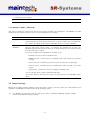
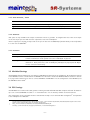
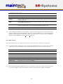
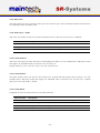
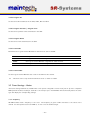
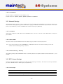
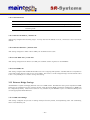
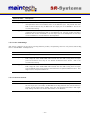
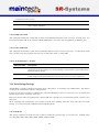
MiniMux Firmware
User’s Manual
Contents
0 Definition
4
1 Frontpanel
1.1 Status Screen . . . . . . . . . . . . . .
1.2 Configuration Menu . . . . . . . . . . .
4
4
5
2 Controlling the MiniMux via the RS232
2.1 Establishing a Connection . . . . . . . .
2.2 Changing Settings . . . . . . . . . . . .
5
5
6
3 Menu Structure
3.1 Port Configuration . . . . . . . . . . . .
3.1.1 TS x Input Mode / TS x Mode .
3.1.2 Multiplexer Mode / MUX mode
3.2 Output Settings . . . . . . . . . . . . .
3.2.1 Clock direction / Clock . . . . .
3.2.2 Clockrate . . . . . . . . . . . .
3.2.3 Framesize . . . . . . . . . . . .
3.3 MiniMod Settings . . . . . . . . . . . .
3.4 PSI Settings . . . . . . . . . . . . . . .
3.4.1 PSI Table Generator / PSI Tables
3.4.2 Stream ID . . . . . . . . . . . .
3.4.3 Network ID . . . . . . . . . . .
3.4.4 Repetition . . . . . . . . . . . .
3.4.5 Network Name . . . . . . . . . .
3.4.6 Upload PSI tables . . . . . . . .
3.5 TS In Settings . . . . . . . . . . . . . .
3.5.1 Clockrate . . . . . . . . . . . .
3.5.2 PSI Tables . . . . . . . . . . . .
3.6 Encoder Settings / TTX Settings . . . .
3.6.1 System Bitrate . . . . . . . . .
3.6.2 Video Input . . . . . . . . . . .
3.6.3 Video Format . . . . . . . . . .
3.6.4 Video Resolution / Resolution .
3.6.5 Video GOP Mode / GOP Mode
6
6
6
8
8
8
9
9
9
9
10
10
10
10
10
10
10
11
11
11
11
11
12
13
13
3.6.6 Video GOP Size / GOP Size . .
3.6.7 Video AGC . . . . . . . . . . . .
3.6.8 Video Gain . . . . . . . . . . . .
3.6.9 Audio Input / Audio . . . . . .
3.6.10 Audio Channel . . . . . . . . . .
3.6.11 Audio Volume . . . . . . . . . .
3.6.12 Audio Mode . . . . . . . . . . .
3.6.13 Audio Samplerate / Samplerate
3.6.14 Audio Bitrate / Bitrate . . . . .
3.6.15 Program Video PID / Video PID
3.6.16 Program Audio PID / Audio PID
3.6.17 Program PMT PID / PMT PID
3.6.18 Teletext PID . . . . . . . . . . .
3.6.19 Program ID . . . . . . . . . . .
3.6.20 Program Provider / Program Prov.
3.6.21 Program Name . . . . . . . . .
3.6.22 LCN mode . . . . . . . . . . . .
3.6.23 LCN number . . . . . . . . . . .
3.7 Tuner Settings – Basics . . . . . . . . .
3.7.1 Frequency . . . . . . . . . . . .
3.7.2 PSI Tables . . . . . . . . . . . .
3.8 Tuner Settings – DVB-T . . . . . . . .
3.8.1 Frequency . . . . . . . . . . . .
3.8.2 Bandwidth . . . . . . . . . . . .
3.9 Tuner Settings – DVB-S . . . . . . . . .
3.9.1 Frequency . . . . . . . . . . . .
3.9.2 Symbolrate . . . . . . . . . . .
3.9.3 LNC Power . . . . . . . . . . .
3.9.4 LNC 22kHz Tone . . . . . . . .
3.10 Tuner Settings – DVB-C . . . . . . . .
3.10.1 Frequency . . . . . . . . . . . .
3.10.2 Symbolrate . . . . . . . . . . .
3.10.3 Constellation . . . . . . . . . . .
3.11 Network Settings . . . . . . . . . . . .
3.11.1 IP Address . . . . . . . . . . . .
–1–
13
13
14
14
14
14
14
15
15
15
15
15
15
16
16
16
16
16
16
16
17
17
17
17
17
17
18
18
18
18
18
18
19
19
19
3.11.2 Subnet Mask . . . . . . . . . .
3.11.3 Default Gateway / Gateway . . .
3.12 RTP Output Settings . . . . . . . . . .
3.12.1 RTP Output . . . . . . . . . . .
3.12.2 SDP Announce . . . . . . . . .
3.12.3 Remote IP Address / Remote IP
3.12.4 Remote UDP Port / Remote Port
3.12.5 Local UDP Port / Local Port . .
3.12.6 RTP SSRC ID . . . . . . . . . .
3.13 Ethernet Bridge Settings . . . . . . . .
3.13.1 DVB⇒ETH Bridge . . . . . . .
3.13.2 ETH⇒DVB Bridge . . . . . . .
3.13.3 ETH Flow Control . . . . . . . .
3.13.4 DVB⇒ETH PID . . . . . . . . .
3.13.5 ETH⇒DVB PID . . . . . . . . .
3.13.6 TS Passthrough / TS Pass . . .
3.14 Serial Bridge Settings . . . . . . . . . .
3.14.1 Baudrate . . . . . . . . . . . . .
3.14.2 Injection . . . . . . . . . . . . .
3.14.3 Extraction . . . . . . . . . . . .
3.14.4 Injection PID . . . . . . . . . .
3.14.5 Extraction Port . . . . . . . . .
3.14.6 Extraction PID . . . . . . . . .
19
19
19
19
20
20
20
20
20
20
20
21
21
22
22
22
22
22
23
23
4 Verbose Status Report
4.1 Product/Version Information
4.2 Global Status . . . . . . . .
4.3 Input Status . . . . . . . . .
4.4 Input Port Status . . . . . .
4.5 ASI Input Status . . . . . . .
4.6 Tuner Status . . . . . . . . .
4.7 Encoder Status . . . . . . .
4.8 Output Status . . . . . . . .
4.9 MiniMod Status . . . . . . .
4.10 PSI Status . . . . . . . . . .
4.11 Ethernet Link Status . . . .
4.12 RTP Output Status . . . . .
–2–
.
.
.
.
.
.
.
.
.
.
.
.
.
.
.
.
.
.
.
.
.
.
.
.
.
.
.
.
.
.
.
.
.
.
.
.
.
.
.
.
.
.
.
.
.
.
.
.
.
.
.
.
.
.
.
.
.
.
.
.
.
.
.
.
.
.
.
.
.
.
.
.
23
23
24
24
24
24
24
25
25
26
27
27
28
28
29
29
5 Status Codes
30
6 MiniMod Remote Control
30
2010-08-25
12:16
The information in this manual was compiled with care and to our best knowledge; nevertheless there are probably
some errors left in this document. We do not take legal or any other responsibility for the correctness of any
information.
We are happy to receive your feedback. If you found an error or think that something should be explained in greater
detail, don’t hesitate to contact us.
This document is protected by copyright law. All trademarks are owned by their respective owners.
maintech GmbH
Otto-Hahn-Straße 15
D-97204 H¨
ochberg
Germany
Phone +49 (931) 40 70 6 90
Fax +49 (931) 40 70 6 53
Web http://www.maintech.de
EMail [email protected]
–3–
0 Definition
The SR-Systems MiniMux is a small, efficient two-port DVB transport stream multiplexer with optional Ethernet
output. The firmware provided by maintech allows the control of other SR-Systems components like NIMs, ASI
in/out and the MiniMod.
1 Frontpanel
The MiniMux can be controlled via an optional LCD/keypad unit connected to the frontpanel connector. The
frontpanel consists of a LC Display, several LEDs and buttons.
¶
·
¸
¹
º
»
J
∗
N
ok
H
÷
I
F
Figure 1: Frontpanel display and button arrangement
¶
·
¸
¹
º
»
Power LED
Input 1 Status LED
Input 2 Status LED
FPGA Status LED
Output Device Status LED
MiniMod ON-AIR LED
F
ok
N H
J I
∗
÷
Enter and exit the menu, abort data entries
Edit the current menu item and commit the changes
Browse menu categories, change character while editing an item
Browse menu items within a category, move cursor while editing an item
Switch display backlight on and off
not used
1.1 Status Screen
Under normal conditions, the frontpanel display shows the MiniMux status screen. On this screen, the first line
shows the product name, which can be slightly different from the example shown here. The second line shows the
current status code. See the MiniMux Status Codes in section 5 on page 30 for a list of possible messages and their
meaning.
Figure 2: MiniMux status screen without and with error message
–4–
1.2 Configuration Menu
F button enters the configuration menu.
Whenever you see the status screen on the frontpanel display, pushing the N and H buttons. The J and
The menu items are grouped in various categories. To select a category, use the I buttons will browse the items within the selected category. Use the N and H buttons again to select a different
category. See MiniMux Menu Structure in section 3 on page 6 for a list of all available categories and menu items.
ok button to edit the menu item currently displayed. Press the F button to exit the menu and return to
Press the the status screen.
Figure 3: Category and menu item selection
ok button, the value can be changed with the J and I buttons. If the
After selecting an item for editing with the J and I buttons move the
item does not represent a distinct set of options but a number or a text string, the N and H change the character under the cursor. Use the ok button to save the changes and press the
cursor and F button to revert the modifications and return to the item selection.
Figure 4: Editing an item with distinct options and a string item
2 Controlling the MiniMux via the RS232
All configuration options that are available on the frontpanel can also be modified via the RS232 interface on the
MiniMux PCB. Please refer to the MiniMux hardware datasheet1 for the pinout.
2.1 Establishing a Connection
The RS232 interface can be used with standard terminal software, e.g. HyperTerminal (included with some versions
of the Windows operating system), Putty2 or any other VT100 compatible terminal software. Set your PC serial port
to 115200 Baud, eight bits per character, no parity, one stopbit (115k2-8N1) and disable any flow control.
When powering up your MiniMux, you should see a boot message similar to this example:
DVB Minimux Firmware V6.30
(c) 2008-2009 maintech GmbH
FPGA firmware v022 successfully uploaded
[ETH] MAC:no IP:no RTPOut:no
1
2
MiniMux hardware datasheet: http://www.maintech.de/fileadmin/Datasheets/DVB-MiniMux-v2.8 Datasheet-v1.1 en.pdf
Download Putty at http://www.chiark.greenend.org.uk/˜sgtatham/putty/download.html
–5–
2.2 Changing Settings
After the boot process is complete, the MiniMux displays its main menu, which also can be re-displayed by pressing
Enter in the terminal software.
Minimux Mainmenu
1) show status
2) Port configuration
3) Output Settings
4) PSI Settings
5) Serial Bridge Settings
6) CSA/BISS Settings
> _
The contents of the main menu depend on the connected transport stream sources and other settings – a tuner will
need other settings than the MPEG2 encoder.
A menu option is selected by entering its number followed by pressing Enter .
3 Menu Structure
3.1 Port Configuration
3.1.1 TS x Input Mode / TS x Mode
This menu item tells the MiniMux, what kind of devices are connected to the TS input connectors. The item appears
once for each of the two TS input ports.
–6–
Selected Value
Description
disabled
The MiniMux will not use the TS input port
MPEG Encoder
The MiniMux will configure and control an SR-Systems MPEG2 encoder module connected to the TS input port
Tuner
The MiniMux will configure and control an SR-Systems tuner module (NIM). Supported
tuner modules are:
• DVB-S tuner (Datasheet: http://www.maintech.de/DSNS1)
• STV0297 DVB-C tuner (Datasheet: http://www.maintech.de/DSNC1)
• DiBcom
3000
DVB-T
tuner
(diversity
or
single)
(Datasheet:
http://www.maintech.de/DSNTD or http://www.maintech.de/DSNT1)
• NXT6000 DVB-T tuner
With firmware version 6.34 or later, the MiniMux will also control SR-Systems intelligent
tuner modules. Intelligent tuner modules can be used standalone and be configured via
display or serial port. When they are connected to a MiniMux with firmware version
6.34 or later, the MiniMux will control the tuner module, and the tuner’s local settings
are disabled. Plase note that for this feature the NIM’s firmware version must be 0.28
or later. Supported intelligent tuner modules are:
• ATSC tuner (Datasheet: http://www.maintech.de/DSIA1)
• DiBcom 7000 (Datasheet: http://www.maintech.de/DSIT1)
• DVB-S/S2 tuner (Datasheet: http://www.maintech.de/DSIS2)
The MiniMux automatically detects the connected tuner type.
ASI
The MiniMux will control an SR-Systems ASI input module (ASI-In) on the TS input
port.
TTX
The MiniMux will configure and control an SR-Systems MPEG2 encoder with TeleText
inserter connected to the TS input port.
generate clk
A transport stream is expected on the TS input port. The MiniMux will generate the
TS clock with a clock rate configured in the menu item TS In x Settings. The data will
be latched on rising clock edge.
external clk
A transport stream is expected on the TS input port. The MiniMux will expect a TS
clock from the connected device. The data will be latched on rising clock edge. Use
this setting when connecting one of the following devices:
• MiniMux or MidiMux multiplexer
(See the maintech application note http://www.maintech.de/fileadmin/Downloads
/ChainingMultiplexers.pdf for information on how to chain multiplexers.)
• legacy 4-TS multiplexer
continued on next page...
–7–
...continued from previous page
Selected Value
Description
3.1.2 Multiplexer Mode / MUX mode
This option controls how TS data from the two input ports is handled in the multiplexer. The MiniMux can either
combine the data from both ports or give to one port preference over another.
Selected Value
Description
multiplex
The data from both input ports is combined inside the multiplexer. Incoming transport
stream packets from both input ports are sent to the TS output port or the Ethernet
port. This is the default mode where the MiniMux works as a classic multiplexer.
1-over-2
2-over-1
Only one of both input ports will be forwarded to the TS output or the Ethernet port.
One port has priority over the other – so whenever the priorized port is active, the
MiniMux will output the data from that port. If the priorized port is not active, the data
from the other port is output.
If a port is considered active, depends on its input mode:
• disabled: the port is never considered active.
• MPEG encoder / TTX: the port is considered active if the encoder is booted and
running.
• Tuner: the port is considered active if the tuner is locked onto an RF signal.
• ASI: the port is considered active if the ASI input module is locked onto an ASI
signal.
• generate clk / external clk: the port is always considered active.
You can use this mode to build a redundant ASI input.
The current status of the input ports (active or not) is shown in the MiniMux status
report.
3.2 Output Settings
Options in the Output Settings submenu control how data is output on the TS output port. This submenu is not
available if the MiniMux was ordered with the IP Streaming option.
+ If a MiniMod is connected to the TS output port, there is a submenu MiniMod Settings available
instead of the submenu Output Settings.
–8–
3.2.1 Clock direction / Clock
Selected Value
Description
external
The MiniMux expects a TS clock signal on the TS output port.
generate
The MiniMux generates a TS clock signal on the TS output port.
3.2.2 Clockrate
This option is only available if the output clock direction is set to generate. It configures the rate of the clock output
on the TS output port and with that the output data rate of the multiplexer.
The TS output port outputs one byte each clock cycle. A data rate of 30000 kbps (thousand bits per second) results
in a clock rate of 6000 kHz3 .
3.2.3 Framesize
Selected Value
Description
188 Byte
The data on the TS output port is sent in TS packets without Reed-Solomon error
correction information. Each packet has a size of 188 Bytes of payload.
204 Byte
The data on the TS output port is sent in TS packets with Reed-Solomon error correction
information. Each packet has a size of 204 Bytes (188 Bytes of payload plus 16 Bytes
of error correction information).
3.3 MiniMod Settings
The MiniMod Settings submenu is only visible if a MiniMod was detected at the TS Output. All modulation settings
of the MiniMod can be controlled from the MiniMux via this menu. Please see MiniMod Remote Control in section
6 on page 30 for instructions on how to connect MiniMod and MiniMux. For the configuration of the MiniMod, see
the MiniMod User’s Guide.4
3.4 PSI Settings
The MiniMux has a built-in PSI table generator which generates ETSI EN 300 468 compliant PSI and SI tables for
up to two connected MPEG encoders or – in extended mode – for an arbitrary number of external services.
The configuration for the extended mode is created with the help of our maintech Mux Configurator5 and uploaded
to the multiplexer via XModem.
3
4
5
See the maintech Application Note About Bitrates: http://www.maintech.de/fileadmin/Datasheets/Bitrates.pdf for more information on the clock and data rates on transport stream ports
http://www.maintech.de/fileadmin/Downloads/MiniModUsersGuide.pdf
See http://www.maintech.de/en/support/information/ for the MuxConfigurator
–9–
3.4.1 PSI Table Generator / PSI Tables
Selected Value
Description
disabled
The table generator in the MiniMux is disabled.
simple
The simple table generator, which generates tables for the encoders directly connected
to the MiniMux, is enabled.
extended
The extended table generator, which is configured with the help of the maintech Mux
Configurator, is enabled.
3.4.2 Stream ID
Set the transport stream ID that is transmitted in PAT, NIT and SDT for the encoded services.
3.4.3 Network ID
Set the network ID that is transmitted in the NIT for the encoded services.
3.4.4 Repetition
Set the PSI table repetition time in ms. Valid values are between 25 ms and 500 ms. Setting the repetition rate to
250 ms results in the complete set of PSI tables being transmitted 4 times per second.
3.4.5 Network Name
Set the network name that is transmitted in the NIT for the encoded services.
3.4.6 Upload PSI tables
+ This menu item is only available if the extended table generator is enabled. It is also only accessible
via the serial port.
Select this menu item to upload a binary configuration file generated by the maintech MUX configurator. After
selection, you need to upload the file via XModem.
3.5 TS In Settings
The TS In Settings submenu is shown for each TS input that is configured to generate clock or external clock.
– 10 –
3.5.1 Clockrate
+ The menu item Clockrate is only shown if the TS input is configured to generate clock.
The TS input port reads one byte each clock cycle. A data rate of 30000 kbps (thousand bits per second) results in
a clock rate of 6000 kHz. Please note that the clock rate at TS input ports is calculated for 204 Byte packets6 .
3.5.2 PSI Tables
This menu item controls if PIDs in the range from 0x0000 to 0x001F are passed through to the multiplexer. In a
standard transport stream those PIDs contain the PSI tables, and therefore this option can be used to block those
tables.
Selected Value
Description
pass
PSI Tables are not blocked.
block
PSI Tables are blocked.
3.6 Encoder Settings / TTX Settings
The Encoder Settings (TTX Settings) submenu is shown for each TS input that is configured to MPEG2 Encoder
(TTX ) (see 3.1.1).
3.6.1 System Bitrate
Set the encoder’s system bit rate (audio, video and tables) to the given value. The modulator does not check if your
configured system bitrate fits into the bandwidth provided by the configured modulation settings. The user has to
make sure that the system bitrate is at least 3% below the modulation bitrate. Please enter a bitrate value based
on 188-byte-packets in kBit/s with possible values between 1000 kBit/s and 20000 kBit/s. If the given value is too
low, the encoding process will stop at the first buffer overflow.
3.6.2 Video Input
This selects the used hardware input for the video signal.
Selected Value
Description
disabled
Do not encode a video signal. The stream will be announced as radio service.
continued on next page...
6
See the maintech Application Note About Bitrates: http://www.maintech.de/fileadmin/Datasheets/Bitrates.pdf for more information on the clock and data rates on transport stream ports.
– 11 –
...continued from previous page
Selected Value
Description
CVBS
Encode signal from the encoder’s CVBS input.
YC
Encode signal from the encoder’s Y/C (S-Video) input.
YCbCr
Encode YCbCr signal from the encoder’s external video connector. Pin 10 is Y, pin 12
is Cb, Pin 14 is Cr.
RGB
Encode RGB video signal from the encoder’s external video connector. Pin 10 is green,
pin 12 is blue, pin 14 is red.
SCART
Encode RGBS (RGB with external sync) video signal from the encoder’s external video
connector. Pin 8 is sync, pin 10 is green, pin 12 is blue, pin 14 is red.
SDI
Encode signal from the attachable SDI input board.
+ YCbCr, RGB and SCART are only available if a newer encoder board with TVP video decoder-chip is
connected. Older encoders with SAA video decoder only support CVBS and Y/C. See the SR-Systems
MPEG encoder datasheet for information about the external video connector: http://download.srsystems.de/Desc/MPEG-Encoder-V4 Desc-en 075dpi.pdf
3.6.3 Video Format
The Video Format menu item configures the encoder to the format that is used on the input signal.
+ The Video Format configuration is not available when SDI is selected on an encoder with a new SDI
input extension board. The SDI extension board will autodetect the video format in that case.
Selected Value
Description
PAL
Standard PAL television signal
PAL-60
The video signal is interpreted as PAL-60 (PAL with 60 Hz and 525 lines)
PAL-M-60
The video signal is interpreted as PAL-M (PAL with 60 Hz and 525 lines)
PAL-N
The video signal is interpreted as PAL-60 (PAL with 60 Hz and 525 lines)
NTSC
The video signal is interpreted as NTSC
NTSC-4.43
NTSC with color carrier at 4.43 MHz
SECAM
The video signal is interpreted as SECAM
+ PAL-60, PAL-M, PAL-N and NTSC-4.43 are only available if a newer encoder with TVP video decoder
is connected. Older encoders with SAA video decoder only support PAL, NTSC and SECAM.
– 12 –
3.6.4 Video Resolution / Resolution
Selected Value
Description
D1
The video image is encoded with full resolution: 720x576
HD1
The video image is encoded with half resolution: 360x576
CIF
The video image is encoded with quarter resolution: 360x288
3.6.5 Video GOP Mode / GOP Mode
The GOP Mode menu item defines how the encoder uses different frame types while encoding the video stream.
Selected Value
Description
I
Each GOP consists only of I-frames
IP
The encoder uses one I-frame and then only P-frames inside a GOP. For a GOP size
(see 3.6.6) of ten, the resulting GOP will look like this: IPPPPPPPPP.
IBP
The encoder uses an I-frame at the beginning of the GOP and encodes the rest in B and
P frames. For a GOP size of ten, the resulting GOP will look like this: IBPBPBPBPB.
IBBP
The encoder uses an I-frame at the beginning of each GOP and encodes the rest in B and
P frames. For a GOP size of ten, the resulting GOP will look like this: IBBPBBPBBP.
3.6.6 Video GOP Size / GOP Size
The GOP Size menu item defines how long each group of pictures from the encoder will be. Possible values are from
1 to 250. Depending on the GOP Mode setting, this value might be rounded up to the next multiple of 2 or 3.
3.6.7 Video AGC
The Video AGC menu item controls the automatic gain control of the video input.
Selected Value
Description
disabled
The video gain is set manually using the Video Gain setting.
enabled
The automatic gain control of the video input is active.
+ The video AGC and video gain settings are not available for older encoders with SAA video ADC. If
the input is set to SDI, the video AGC is also not available.
– 13 –
3.6.8 Video Gain
The Video Gain menu item controls the video gain if the automatic gain control is disabled. Possible values are from
0 to 300 where 148 is the default value.
3.6.9 Audio Input / Audio
This menu item decides if audio is encoded and transmitted. For video-only mode, set this to disabled.
Selected Value
Description
disabled
No audio data is encoded and transmitted.
analog
Audio is encoded from the encoder’s analog inputs.
SDI
Audio is extracted and encoded from the attached SDI input port.
3.6.10 Audio Channel
This menu item selects the audio channels for de-embedding from SDI. It is only available when a SDI input module
with support for embedded audio is attached to the TS input port.
Possible values are: 1.12, 1.34, 2.12, 2.34, 3.12, 3.34, 4.12 and 4.34.
3.6.11 Audio Volume
The Audio Volume menu item lets the user attenuate the received SDI audio signal before encoding. It is only
available when a SDI input module with support for embedded audio is attached to the TS input port. Possible
values are in the range 0 dB to -60 dB.
3.6.12 Audio Mode
Configures the audio channel mode for the encoded audio data.
Selected Value
Description
Stereo
The audio from the left and right input is encoded as stereo signal.
Joint Stereo
Stereo encoding with better quality but less stereo channel separation.
Dual Channel
The signal from the left and right input is encoded as two separate mono channels.
Single Channel
The audio is encoded as single mono channel.
– 14 –
3.6.13 Audio Samplerate / Samplerate
Configures the sample rate for analog audio input.
Possible values are: 32 kHz, 44.1 kHz, 48 kHz.
3.6.14 Audio Bitrate / Bitrate
Configures the bitrate that the encoder uses for audio encoding. More bitrate results in better audio quality. Possible
values depend on the selected Audio Mode (see 3.6.12).
Possible values for Stereo, Joint Stereo and Dual Channel: 64, 96, 112, 128, 160, 192, 224 and 256 kBit/s. CD
quality is reached at approx. 224 kBit/s.
Possible values for Single Channel: 32, 48, 56, 64, 80, 96, 112, 128, 160 and 192 kBit/s. CD quality is reached at
approx. 160 kBit/s.
3.6.15 Program Video PID / Video PID
Set the DVB PID used to transmit the video data. Valid values are between 0x0020 and 0x1FFE. The video PID
must be unique – make sure that it is not used for anything else (e.g. audio, PMT, etc.) If you plan to multiplex
multiple streams, make sure that the video PID is unique among all other PIDs in the resulting multiplex.
3.6.16 Program Audio PID / Audio PID
Set the DVB PID used to transmit the audio data. Valid values are between 0x0020 and 0x1FFE. The audio PID
must be unique – make sure that it is not used for anything else (e.g. video, PMT, etc.) If you plan to multiplex
multiple streams, make sure that the audio PID is unique among all other PIDs in the resulting multiplex.
3.6.17 Program PMT PID / PMT PID
Set the DVB PID used to transmit the PMT for the encoded service. Valid values are between 0x0020 and 0x1FFE.
The PMT PID must be a unique PID that is not used for video, audio or anything else. If you plan to multiplex
multiple streams, make sure that the PMT PID is unique in the whole multiplex.
3.6.18 Teletext PID
Set the DVB PID used to transmit teletext data for the encoded service. Valid values are between 0x0020 and
0x1FFE. The teletext PID must be a unique PID that is not used for video, audio, PMT or anything else. If you plan
to multiplex multiple streams, make sure that the teletext PID is unique in the whole multiplex.
+ This menu item is shown only if a TTX inserter is connected to the TS input and the input mode is
set to TTX.
– 15 –
3.6.19 Program ID
Set the service ID transmitted in the PAT, PMT, NIT and SDT.
3.6.20 Program Provider / Program Prov.
Set the service provider name transmitted in the SDT.
3.6.21 Program Name
Set the service name transmitted in the SDT.
3.6.22 LCN mode
Determines if a Logical Channel Number for this service is sent in the NIT.
Selected Value
Description
disabled
No Logical Channel Number is signalled for the service.
visible
The Logical Channel Number is signalled as visible channel.
hidden
The Logical Channel Number is signalled as hidden command.
3.6.23 LCN number
Set the Logical Channel Number that is sent in the NIT for this channel.
+ This menu item is only shown if LCN mode is set to visible or hidden.
3.7 Tuner Settings – Basics
The Tuner Settings submenu is available when a TS input is configured to Tuner mode (see 3.1.1) and a compatible
NIM (network interface module) is attached to the TS input port. The MiniMux will automatically detect the tuner
type and display the corresponding settings.
3.7.1 Frequency
All NIM modules need a frequency to tune onto. The frequency is given in kHz and refers to the center of the
channel. See the specific sections for DVB-T, -S and -C for the allowed ranges.
– 16 –
3.7.2 PSI Tables
This menu item configures if the PSI Tables (PIDs below 0x20) are forwarded to the multiplexer or blocked at the
tuner input port.
Selected Value
Description
pass
All PIDs from the tuner will be passed to the multiplexer.
block
Only PIDs with values of 0x20 or above are passed to the multiplexer. PSI tables which
are on the PIDs below 0x20 are blocked.
3.8 Tuner Settings – DVB-T
These menu items are displayed when a DVB-T NIM is attached to the MiniMux.
+ FEC, constellation setting and guard interval are automatically detected from the TPS bits embedded
into the carrier. Only frequency and bandwidth need to be set to receive a signal.
3.8.1 Frequency
Set the reception frequency for the DVB-T tuner in kHz. Valid values are between 145000 kHz and 858000 kHz.
The DVB-T frequency refers to the center of the channel – independently of the bandwidth.
3.8.2 Bandwidth
Set the reception bandwidth for the DVB-T tuner in MHz. Valid values are between 1 MHz and 8 MHz.
3.9 Tuner Settings – DVB-S
These menu items are displayed when a DVB-S NIM is attached to the MiniMux.
3.9.1 Frequency
Set the reception frequency for the DVB-S tuner in kHz. Valid values are between 950000 kHz and 2150000 kHz.
+ The MiniMux does not account for the LOF of an LNB that you might use. If you use an LNB to
receive the DVB-S signal, you need to calculate the IF and set the frequency to that value.
– 17 –
3.9.2 Symbolrate
Set the reception symbol rate for the DVB-S tuner in kSym/s. Valid values are in the range between 1000 kSym/s
and 45000 ksym/s.
3.9.3 LNC Power
Selected Value
Description
Off
The DVB-S tuner does not supply power to the HF input.
13V
The DVB-S tuner supplies 13V to the HF input.
18V
The DVB-S tuner supplies 18V to the HF input.
+ The supply of 13 or 18V to the HF input works only if you have connected an additional 24V power
supply to your DVB-S tuner. The NIM does not contain a step-up regulator.
3.9.4 LNC 22kHz Tone
Selected Value
Description
Off
The DVB-S tuner does not apply 22kHz to the LNC power supply.
On
The DVB-S tuner applies 22kHz signal tone to the LNC power supply.
+ The 22kHz tone works only if you have connected an additional 24V power supply to your DVB-S
tuner and if you have selected 13V or 18V as LNC power.
3.10 Tuner Settings – DVB-C
These menu items are displayed when a DVB-C NIM is attached to the MiniMux.
3.10.1 Frequency
Set the reception frequency for the DVB-C tuner in kHz. Valid values are between 47000 kHz and 866000 kHz.
3.10.2 Symbolrate
Set the reception symbol rate for the DVB-C tuner in kSym/s. Valid values are in the range between 1000 kSym/s
and 7000 ksym/s.
– 18 –
3.10.3 Constellation
Set the reception constellation for the DVB-C tuner.
Possible values are: QAM16, QAM32, QAM64, QAM128 and QAM256.
3.11 Network Settings
The Network Settings menu is used to configure the network identity of the MiniMux itself. After you have set up
those network settings properly, you should be able to ping your MiniMux from hosts on your network. This menu
item is only available if you have a MiniMux with an RTP output port (Ethernet).
3.11.1 IP Address
This setting configures the IP address of the MiniMux itself. You have to choose an IP address which is unique in
your network.
3.11.2 Subnet Mask
The subnet mask tells the MiniMux which IP address range lies within its broadcast domain.
+ If you do not intent to use the MiniMux in combination with one or more IP routers, you can set
subnet mask and default gateway to 0.0.0.0.
3.11.3 Default Gateway / Gateway
The default gateway tells the MiniMux where to send IP packets for recipients outside its broadcast domain / local
network.
3.12 RTP Output Settings
Settings in the RTP Output Settings menu affect the IP Streaming of TS Data. This menu item is only available if
you have a MiniMux with an RTP output port (Ethernet).
3.12.1 RTP Output
Selected Value
Description
enabled
The MiniMux tries to stream its output data to the configured target.
disabled
IP Streaming is disabled, multiplexer output is discarded.
– 19 –
3.12.2 SDP Announce
Selected Value
Description
enabled
The MiniMux announces its RTP stream on the network using the SAP/SDP protocol.
disabled
The MiniMux does not announce its RTP stream on the network. This does not influence
streaming itself.
3.12.3 Remote IP Address / Remote IP
This setting configures the streaming target. You may enter the IP address of a host, a multicast or even a broadcast
address.
3.12.4 Remote UDP Port / Remote Port
This setting configures to which remote UDP port the RTP stream is sent.
3.12.5 Local UDP Port / Local Port
This setting configures from which local UDP port the RTP stream originates on the MiniMux.
3.12.6 RTP SSRC ID
This setting configures which SSRC ID should be set in the outgoing RTP packets. See RFC 3550 for an explanation
of the RTP packet structure and the role of the SSRC. The value is a 32 bit unsigned integer and the default value
is zero. You probably do not need to change this setting.
3.13 Ethernet Bridge Settings
The MiniMux is capable of bridging Ethernet data over a DVB stream. Raw Ethernet data gets encapsulated in DVB
frames and is transmitted over the transport stream. Both directions (DVB to Ethernet and Ethernet to DVB) can
be configured separately. These menu items are only available if your MiniMux is part of an Ethernet Bridge and
contains appropriate FPGA firmware.
3.13.1 DVB⇒ETH Bridge
This setting configures the process of reading Transport Stream packets, deencapsulating them and transmitting
them on the Ethernet port.
– 20 –
Selected Value
Description
disabled
Ethernet deencapsulation is disabled.
enabled(block)
The MiniMux receives TS packets with the PID configured under DVB⇒ETH PID,
deencapsulates them and transmits them on the Ethernet port. All packets with this
PID are also blocked so they do not reach the output port of the MiniMux. This is the
recommended setting.
enabled(pass)
The MiniMux receives TS packets with the PID configured under DVB⇒ETH PID, deencapsulates them and transmits them on the Ethernet port. The TS packets containing
Ethernet data are also forwarded to the TS output port of the Multiplexer so that they
can be forwarded to another Ethernet deencapsulator.
3.13.2 ETH⇒DVB Bridge
This setting configures the process of receiving Ethernet packets, encapsulating them into TS packets and sending
them to the MiniMux’ TS Output Port.
Selected Value
Description
disabled
Ethernet encapsulation is disabled.
enabled(block)
The MiniMux receives Ethernet frames and encapsulates them in TS packets with the
PID configured under ETH⇒DVB PID. Packets with this PID coming from the input
ports are blocked so that they do not disturb the Ethernet data stream. This is the
recommended setting.
enabled(pass)
The MiniMux receives Ethernet frames and encapsulates them in TS packets with the
PID configured under ETH⇒DVB PID. Packets with this PID coming from the input
ports are not blocked and are therefore mixed with the encapsulated Ethernet data. This
might lead to unexpected behaviour.
3.13.3 ETH Flow Control
Selected Value
Description
enabled
When the ETH⇒DVB Bridge is enabled and the MiniMux is receiving more data than
the TS output port can handle, the MiniMux is sending Ethernet flow control frames to
prevent the link partner from sending more data that would be discarded. This might
help dealing with short but intense data bursts on the Ethernet.
continued on next page...
– 21 –
...continued from previous page
Selected Value
Description
disabled
The MiniMux will not send flow control frames on the Ethernet port. If data is sent too
fast, it will be discarded.
3.13.4 DVB⇒ETH PID
This configures the PID that is used when receiving encapsulated Ethernet data from one of the TS input ports. You
should use the same PID as you entered as ETH⇒DVB PID on the device that encapsulates the Ethernet data.
3.13.5 ETH⇒DVB PID
This configures the PID that is used when encapsulating Ethernet data to the TS output port. You should use a PID
that is unique in the whole system and never mix it with Video, Audio or other PIDs.
3.13.6 TS Passthrough / TS Pass
Selected Value
Description
disabled
No other TS packets than the encapsulated Ethernet data will be forwarded from the TS
input ports to the TS output port. Use this setting to prevent data loops in bidirectional
Ethernet bridging setups.
enabled
Whilst briding Ethernet data, the MiniMux works just as a standard multiplexer would.
It will multiplex and forward data from the TS input ports to the TS output port.
3.14 Serial Bridge Settings
The MiniMux is capable of bridging serial data (from a GPS device, for example) over a DVB stream. This feature
consists of two mechanisms: Injection and Extraction.
Injection means the encapsulation of RS232 data, which the MiniMux receives on a serial port, into TS packets and
sending those packets on the TS output port.
Extraction means reading TS packets with a specific PID from a specific port and transmitting their contents on the
serial port.
When combining both mechanisms, you can build a system that transmits serial data along with video and audio
services. You could even build a bidirectional serial bridge system.
3.14.1 Baudrate
This setting configures the baud rate that is used for transmitting and receiving on the serial port. Possible values
are: 300, 1200, 2400, 4800, 9600, 19200, 38400, 57600, 115200.
– 22 –
3.14.2 Injection
Selected Value
Description
disabled
Serial Injection is disabled.
enabled(block)
The MiniMux reads data from the serial port and embeds this data into the transport
stream using packets with the PID configured under Injection PID. This PID is blocked
on both TS inputs to make sure that the serial link is not disturbed by data from the
TS input. This is the recommended setting.
enabled(pass)
The MiniMux reads data from the serial port and embeds this data into the transport
stream using packets with the PID configured under Injection PID. Packets with that
PID coming from one of the input ports are not blocked. This means that serial data
coming from one of the input ports on this PID gets mixed with the inserted serial data.
This might lead to unexpected behaviour.
3.14.3 Extraction
Selected Value
Description
disabled
Serial Extraction is disabled.
enabled(block)
The MiniMux receives TS packets with the PID configured under Extraction PID from
the port configured under Extraction Port. The contents of those packets are output
on the serial port and the TS packets are not forwarded to the output. This is the
recommended setting.
enabled(pass)
The MiniMux receives TS packets with the PID configured under Extraction PID from
the port configured under Extraction Port. The contents of those packets are output on
the serial port and the TS packets are also forwarded to the output. A second MiniMux
or RS232 extractor could extract the same data or the data could be forwarded to another
receiver.
3.14.4 Injection PID
This menu item configures the PID used for RS232 injection, if enabled. Choose a PID that is unique in your system
– do not mix audio, video or other PIDs with serial data PIDs.
3.14.5 Extraction Port
This menu item configures which MiniMux input port is used for RS232 extraction. Only data coming from that port
will get extracted and transmitted on the RS232 port.
– 23 –
3.14.6 Extraction PID
This menu item configures the PID used for RS232 extraction, if enabled. Choose the same PID as you used as
Injection PID on the device where the RS232 gets injected.
4 Verbose Status Report
When controlling the MiniMux via the RS232 serial port as described in section 2, you can get a verbose status report
from the MiniMux by choosing option 1 (Show Status) in the main menu.
The meanings of the different lines in the verbose status reports are explained in the sections below.
4.1 Product/Version Information
DVB MiniMux CPU V6.9 FPGA 043
This line gives you information about the product (DVB MiniMux), the CPU and the FPGA software versions.
4.2 Global Status
Current Status: running
This line gives you information about the current global status of the MiniMux. The status message shown here is
the same as shown on the frontpanel display. Detailed information on the possible status messages and their meaning
can be found in section 5.
+ In MiniMux software versions prior to V6.28, the global status line is the only line shown in the
verbose status report. We suggest to update your MiniMux to the latest firmware to get the full
verbose status report.
4.3 Input Status
Active inputs: 1 and 2
This status line tells you which of the TS Input Ports are currently active and forwarding their data to the TS output
port or the IP streaming target. See 3.1.2 for an explanation in which cases a port is considered active and how one
port can be priorized over the other.
– 24 –
Status Display
Description
1 and 2
Both ports are active.
1 only
Only port one is active. Port two could be disabled, have an error or be overridden
by port one (if MuxMode is set to 1-over-2).
2 only
Only port two is active. Port one could be disabled, have and error or be overridden by port one (if MuxMode is set to 2-over-1).
none
None of the two TS Input ports is active.
4.4 Input Port Status
IN1: generate clock (30000 kBit/s)
IN2: input disabled
This status line tells you about the status of each TS input port that is set to disabled, external clock or generate
clock. If the port is set to tuner, ASI or encoder, different status lines which are explained in the following sections
are shown.
Status Display
Description
input disabled
The TS input port has been disabled.
external clock
The TS input port has been configured to receive TS clock and data from an
external device.
generate clock
(... kBit/s)
The TS input port has been configured to provide TS clock to and receive data
from an external device. The TS clock is set up to receive the specified bitrate
on the port.
4.5 ASI Input Status
IN1: ASI In HW Error
IN2: ASI In V34 locked
This status line tells you about the status of a TS input port that is set to ASI and the status of the connected ASI
input module. It is only shown if a TS input port is set to ASI.
Status Display
Description
ASI In V... locked
The TS input is ok and locked to a ASI signal. The firmware version of the ASI
input module is shown in the status message.
continued on next page...
– 25 –
...continued from previous page
Status Display
Description
ASI In V... not
locked
The TS input is ok but not locked to a ASI signal.
ASI In HW Error
The ASI input module was not detected or is faulty.
4.6 Tuner Status
IN1: [MB86A15] tuner locked
IN2: [DIB3000 4-Way] tuner error
This status line tells you about the status of a TS input port that is set to tuner and the status of the connected
tuner module (NIM). It is shown only if a TS input port is set to tuner. The type of the detected tuner is displayed
in square brackets.
Status Display
Description
MB86A15 DVB-S
A Fujitsu MB86A15 DVB-S tuner (SR-Systems DVB-S NIM) has been detected.
Tuner settings for DVB-S are shown in the Tuner Settings menu.
STV0297 DVB-C
A ST Microelectronics STV0297 DVB-C tuner (SR-Systems DVB-C NIM) has
been detected. Tuner settings for DVB-C are shown in the Tuner Settings menu.
NXT6000 DVB-T
A NextWave NXT6000 DVB-T tuner (SR-Systems DVB-T NIM) has been detected. Tuner settings for DVB-T are shown in the Tuner Settings menu.
DIB3000 DVB-T
A single DibCom DIB3000 DVB-T tuner (SR-Systems DVB-T NIM) has been
detected. Tuner settings for DVB-T are shown in the Tuner Settings menu.
2x DIB3000
A DibCom DIB3000 dual diversity DVB-T tuner (SR-Systems DVB-T diversity
NIM) has been detected. Tuner settings for DVB-T are shown in the Tuner
Settings menu.
Status Display
Description
tuner not found
No tuner module was detected. Check the cable connecting the MiniMux and
the tuner module.
tuner error
A tuner module was detected, but a fatal error occured while controlling the tuner
module. The MiniMux continues trying to reinitialize the tuner. Check the cable
connections and – if the problem persists – ask for support.
tuner not locked
A tuner module was detected and configured, but it could not lock to a signal.
The MiniMux continues trying to retune to the signal. Check frequency and
modulation settings in the Tuner Settings Menu.
continued on next page...
– 26 –
...continued from previous page
Status Display
Description
tuner locked
A tuner module was detected, configured and locked to a signal.
4.7 Encoder Status
IN1: encoder running
IN2: encoder error (BOOT)
This status line tells you about the status of a TS input port that is set to Encoder and the status of the connected
MPEG-2 encoder module. It is shown only it a TS input port is set to Encoder.
Status Display
Description
encoder error
(BOOT)
The MPEG-2 encoder on the TS Input Port could not be booted. This could
happen if there is no encoder connected, if there is a problem with the cable
between encoder and MiniMux or if the encoder is defective.
encoder error (...)
The MPEG-2 encoder on the TS input port was started but an error occured
during configuration. The abbreviations in the round brackets indicate what part
of counfiguration failed. Possible values are VID, AUD, BR and PID.
encoder running
The MPEG-2 encoder on the TS input port is running.
4.8 Output Status
OUT: generate clock (50000 kBit/s)
This status line tells you about the status of the TS Output Port. It is not shown if your MiniMux has an Ethernet
output because the TS output port is not active then.
Status Display
Description
external clock
The TS output port is configured to accept a TS clock from an external device
for TS data output.
generate clock
(... kBit/s)
The TS output port is configured to generate TS clock for TS data output. The
TS clock rate is set to transmit the specified amount of data.
Incompatible HW:...
SW...
The device connected to the TS output port was recognized, but its firmware is
incompatible with the current MiniMux firmware. Try to update both components
to their latest firmware versions.
continued on next page...
– 27 –
...continued from previous page
Status Display
Description
MiniMod V...
detected
The MiniMod connected to the TS output port was recognized and can now
be controlled from the MiniMux. A MiniMod Settings menu appears and is be
accessible from the MiniMux main menu. The MiniMux output port and the
MiniMod input port are automatically configured to ensure smooth data flow.
4.9 MiniMod Status
MiniMod: ON-AIR
This status line shows the global status of the MiniMod connected to the MiniMux’ TS output port. See the MiniMod
Firmware Manual7 for a list of possible status messages and their descriptions.
4.10 PSI Status
Basic PSI Generator Active
This line shows the status of the MiniMux’ built-in table generator.
Status Display
Description
PSI Generator
disabled
The MiniMux’ PSI Generator was disabled. The MiniMux will not generate any
PSI or SI tables.
Basic PSI Generator
active
The MiniMux’ Basic PSI Generator is active. The MiniMux will generate PAT,
SDT, NIT and PMTs for the connected MPEG-2 encoders.
Custom PSI/Filter
active
The MiniMux’ Extended PSI Generator is active and a custom tableset and/or
PID filter was uploaded and is now active.
Custom PSI/Filter
incompatible
The custom tableset / PID filter you have uploaded is incompatible with this
MiniMux’ firmware. Please use the latest version of the maintech Mux Configurator (see http://www.maintech.de/en/support/information/ ) to generate the
.mbn-File and update the MiniMux firmware to the latest version.
Custom PSI/Filter
empty
The MiniMux’ Extended PSI Generator is active but no custom tableset and/or
PID filter was uploaded. Use the maintech Mux Configurator to set up a custom
table set and/or PID filter. Export this configuration as a .mbn file and upload
this file to the MiniMux.
continued on next page...
7
http://www.maintech.de/fileadmin/Downloads/MiniModUsersGuide.pdf
– 28 –
...continued from previous page
Status Display
Description
Custom PSI/Filter
error (...)
The MiniMux’ Extended PSI Generator is active and an error occured while executing the custom table set or filter program. Please ask for support.
4.11 Ethernet Link Status
ETH Link State: 100 MBit, full duplex
This status line shows the status of the physical Ethernet connection. It is only shown if your MiniMux has Ethernet
support (Ethernet Bridge or IP Streamer).
Status Display
Description
down
No Ethernet connection could be established. Check the Ethernet cable connection.
10 MBit, half duplex
A 10 MBit/s half duplex Ethernet connection has been established.
10 MBit, full duplex
A 10 MBit/s full duplex Ethernet connection has been established.
100 MBit, half duplex
A 100 MBit/s half duplex Ethernet connection has been established.
100 MBit, full duplex
A 100 MBit/s full duplex Ethernet connection has been established.
4.12 RTP Output Status
RTP Output: Streaming to 10.0.0.1 (00:11:22:33:44:55)
This status line shows the status of the IP/RTP Output. It is only shown if your MiniMux has a IP/RTP streaming
output.
Status Display
Description
RTP Output:
disabled
The IP/RTP output streaming is disabled.
RTP Output: No
ARP for ...
The MiniMux could not get an ARP reply for the IP/RTP streaming target. This
could mean that the target is not present in the network or that your network
settings are wrong.
RTP Output:
Streaming to ... (...)
The MiniMux is streaming data to the displayed IP address. On the Ethernet
layer, the shown MAC address is used to transmit the data.
– 29 –
5 Status Codes
Possible status codes that are reported by the MiniMux on its frontpanel:
Status Display
Description
The MiniMux firmware is booting and initializing the hardware. This state is
reported only for a short time during powerup.
The MiniMux is uploading firmware to an MPEG encoder connected to a TS input
port. This state is reported for a short time during powerup and after changing
the TS input mode to MPEG Encoder.
Loading the FPGA failed. This status probably indicates a hardware failure. Please
ask for support.
The TS input mode of TS input port x is set to encoder, but a MPEG encoder
was not detected or an error occurred while starting the encoder. Please make sure
that your encoder is connected properly or try a different encoder if you suspect a
hardware problem.
The TS input mode of TS input port x is set to tuner, but a tuner was not detected
or an error occurred while configuring the tuner. Please make sure that your tuner
is connected properly or try a different tuner if you suspect a hardware problem.
The TS input mode is set to tuner, a tuner was detected, but is not locked to a
signal. Check if your tuner settings are correct and make sure that the tuner gets
a good signal.
The MiniMux is working.
The MiniMux is in an unknown state. This indicates a severe hardware or software
error. Power-cycle your MiniMux and, if the problem persists, ask for support.
6 MiniMod Remote Control
The MiniMux is capable of controlling a MiniMod connected to the MiniMux’ TS output port. This means that you
are able to control all of the MiniMod’s modulation settings from the MiniMux’ RS232 serial port or display/keypad.
To make the MiniMod Remote Control feature work, you need to perform the following steps:
1. Make sure that MiniMod and MiniMux are connected with a Type 1, 1X or 2 cable. We recommend using a
Type 2 cable. A Type 3 cable will not work.8
2. Make sure that the MiniMod’s TS input port is configured to raw TS. The settings for clock direction and
clock edge do not matter – they will be set to the right values automatically.
3. Make sure that your MiniMod has at least Firmware Version 54.40 and your MiniMux has at least Firmware
Version 6.16. Contact us if your hardware has older firmware.
When everything worked well, the menu item Output Settings in the MiniMux main menu will be replaced by MiniMod
Settings. You will also see a MiniMod status line in the MiniMux’ verbose status report.
8
For information about the different cable types, see the maintech cable guide:
http://www.maintech.de/fileadmin/Datasheets/Cable-Guide v1 en-1.pdf
– 30 –
All settings you change in the MiniMod Settings menu are stored on the MiniMod immediately. So if you disconnect
MiniMux and MiniMod, the MiniMod will remember those settings. If you connect a different MiniMod to the
MiniMux, you need to check those settings as the MiniMux will always load them from the MiniMod.
– 31 –