1
No. CP-SP-1176E
AUR450C
Flame Safeguard Control
Dynamic Self Check
Burner Controller
"Communications"
User's Manual
Thank you for purchasing the AUR450C
Flame Safeguard Control Dynamic Self
Check Burner Controller.
This manual contains information for
ensuring the correct use the communication functions of the AUR450C.
Those who design and maintain devices
that use the communication functions
of the AUR450C should read this manual. It also provides necessary information for installation, maintenance, and
troubleshooting. Be sure to keep this
manual nearby for handy reference.
RESTRICTIONS ON USE
This product has been designed, developed and manufactured for general-purpose
application in machinery and equipment.
Accordingly, when used in applications outlined below, special care should be taken to
implement a fail-safe and/or redundant design concept as well as a periodic
maintenance program.
• Safety devices for plant worker protection
• Start/stop control devices for transportation and material handling machines
• Aeronautical/aerospace machines
• Control devices for nuclear reactors
Never use this product in applications where human safety may be put at risk.
IMPORTANT
• Do not use the communications output for control. The communications output of the
AUR450C an output for monitor equipment status and combustion conditions.
• Do not dara write to write-inhibited addresses or to addresses having no description.
Doing so may cause an error in communications or display.
NOTICE
Be sure that the user receives this manual before the product is used.
Copying or duplicating this user’s manual in part or in whole is forbidden. The information and specifications in this manual are subject to
change without notice.
Considerable effort has been made to ensure that this manual is free
from inaccuracies and omissions. If you should find an error or omission, please contact Yamatake Corporation.
In no event is Yamatake Corporation liable to anyone for any indirect,
special or consequential damages as a result of using this product.
©2006 Yamatake Corporation ALL RIGHTS RESERVED
SAFETY PRECAUTIONS
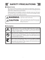
■ About Icons
The safety precautions described in this manual are indicated by various icons.
Please be sure you read and understand the icons and their meanings described
below before reading the rest of the manual.
Safety precautions are intended to ensure the safe and correct use of this product, to prevent injury to the operator and others, and to prevent damage to property. Be sure to observe these safety precautions.
WARNING
CAUTION
Warnings are indicated when mishandling this product
might result in death or serious injury.
Cautions are indicated when mishandling this product
might result in minor injury to the user, or only physical
damage to the product.
■ Examples
Triangles warn the user of a possible danger that may be caused by
wrongful operation or misuse of this product. These icons graphically
represent the actual danger. (The example on the left warns the user of
the danger of electric shock.)
White circles with a diagonal bar notify the user that specific actions are
prohibited to prevent possible danger. These icons graphically represent
the actual prohibited action. (The example on the left notifies the user
that disassembly is prohibited.)
Filled-in black circles instruct the user to carry out a specific obligatory
action to prevent possible danger. These icons graphically represent the
actual action to be carried out. (The example on the left instructs the user
to remove the plug from the outlet.)
i
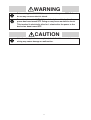
WARNING
Before wiring the 400C/450C, be sure to turn the power OFF. Failure to
do so may cause an electric shock.
Do not touch terminal 1(F) of the main body immediately after the
power has been turned OFF. Doing so may cause an electric shock.
This terminal is electrically alive for 1 minute after the power to the
device has been turned OFF.
CAUTION
After the wiring has been completed, check that it is correct. Incorrect
wiring may cause damage or malfunction.
ii
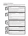
The Role of This Manual
A total of five different manuals are available for the AUR450C. Read them as necessary for your specific requirements. If a manual you require is not available, contact Yamatake Corporation or its dealer.
AUR400C/450C Flame Safeguard Control Dynamic Self Check Burner
Controller
Manual No. CP-SP-1196E
This manual should be read by personnel using the AUR400C/450C for the
first time, those in charge of designing combustion equipment that uses the
AUR400C/450C or designing the hardware for mounting the device in a control panel, and personnel performing maintenance.
The manual gives an overview of the product, its mounting and wiring for
connection to other equipment, its operation, trial-run adjustment, maintenance and inspection, and specifications.
AUR450C Flame Safeguard Control Dynamic Self Check Burner
Controller "Communications"
Manual No. CP-SP-1176E
This manual.
Those using the communications functions of the AUR450C should read this
manual.
It is necessary for making the program of the device that uses AUR450C. An
operation status and various data of AUR450C can be read by using the
communication.
This manual describes a details of display, outline of CPL communications,
communications procedures, a list of communications data, how to remedy
trouble, and communications specifications.
SLP-A45 Smart Loader Package for the AUR450C Flame Safeguard Control
Dynamic Self Check Burner Controller
Manual No. CP-SP-1187E
This manual is supplied with the SLP-A35/SLP-A45 Smart Loader Package.
The manual describes the software used to make various settings for SLPA45 using a personal computer. Personnel in charge of design or setting of a
system using AUR450C must thoroughly read this manual.
The manual describes installation of the software into a personal computer,
operation of the personal computer, various functions, and setup procedures.
AUD300C1000 Flame Safeguard Control Advanced UV Sensor
Manual No. CP-SP-1141E
The manual describes the mounting, wiring, maintenance and inspection,
and troubleshooting when the AUD300C1000 when it is used in a safeguard
control system.
AUD300C2000 Flame Safeguard Control Advanced UV Sensor
Manual No. CP-SP-1170E
The manual describes the mounting, wiring, maintenance and inspection,
and troubleshooting when the AUD300C2000 when it is used in a safeguard
control system.
iii
Contents
SAFETY PRECAUTIONS
The Role of This Manual
Conventions Used in This Manual
Chapter 1.
OVERVIEW
■ Features • • • • • • • • • • • • • • • • • • • • • • • • • • • • • • • • • • • • • • • • • • • • • • • • • • • • • • • • • • • • • • • • • 1
■ Communications functions • • • • • • • • • • • • • • • • • • • • • • • • • • • • • • • • • • • • • • • • • • • • • • 1
Chapter 2.
WIRING
■ RS-485 connections
■ Loader connections
Chapter 3.
• • • • • • • • • • • • • • • • • • • • • • • • • • • • • • • • • • • • • • • • • • • • • • • • • • • • •
• • • • • • • • • • • • • • • • • • • • • • • • • • • • • • • • • • • • • • • • • • • • • • • • • • • • •
3
3
COMMUNICATIONS SETTINGS
■ Station address • • • • • • • • • • • • • • • • • • • • • • • • • • • • • • • • • • • • • • • • • • • • • • • • • • • • • • • • • 4
■ Transmission speed • • • • • • • • • • • • • • • • • • • • • • • • • • • • • • • • • • • • • • • • • • • • • • • • • • • • • 4
■ Data format • • • • • • • • • • • • • • • • • • • • • • • • • • • • • • • • • • • • • • • • • • • • • • • • • • • • • • • • • • • • • • 4
Chapter 4.
COMMUNICATIONS
4-1 Outline of Communications • • • • • • • • • • • • • • • • • • • • • • • • • • • • • • • • • • • • • • • • • • • • • • • • • 5
■ Communications procedures • • • • • • • • • • • • • • • • • • • • • • • • • • • • • • • • • • • • • • • • • • • 5
■ Messaage structure • • • • • • • • • • • • • • • • • • • • • • • • • • • • • • • • • • • • • • • • • • • • • • • • • • • • • 5
■ Data link layer • • • • • • • • • • • • • • • • • • • • • • • • • • • • • • • • • • • • • • • • • • • • • • • • • • • • • • • • • • • 5
■ Application layer • • • • • • • • • • • • • • • • • • • • • • • • • • • • • • • • • • • • • • • • • • • • • • • • • • • • • • • • 8
4-2 Description of Commands • • • • • • • • • • • • • • • • • • • • • • • • • • • • • • • • • • • • • • • • • • • • • • • • • • 9
■ Continuous data read command (RS command) • • • • • • • • • • • • • • • • • • • • • • • • • 9
■ Continuous data write command (WS command)• • • • • • • • • • • • • • • • • • • • • • • 10
■ Fixed length continuous data read command (RD command) • • • • • • • • • • 11
■ Fixed length continuous data write command (WD command) • • • • • • • • • 12
■ Fixed length random data read command (RU command) • • • • • • • • • • • • • • 13
■ Fixed length random data write command (WU command) • • • • • • • • • • • • • 14
4-3 Numeric Representation in the Application Layer • • • • • • • • • • • • • • • • • • • • • • • • • • 15
4-4 Termination Codes • • • • • • • • • • • • • • • • • • • • • • • • • • • • • • • • • • • • • • • • • • • • • • • • • • • • • • • • • 16
4-5 Timing Specifications • • • • • • • • • • • • • • • • • • • • • • • • • • • • • • • • • • • • • • • • • • • • • • • • • • • • • • 17
■ Timing specifications for instruction and response messages • • • • • • • • 17
■ RS-485 driver control timing specifications • • • • • • • • • • • • • • • • • • • • • • • • • • • • 17
iv
Chapter 5.
COMMUNICATIONS DATA
■ Memory map (communications data table) • • • • • • • • • • • • • • • • • • • • • • • • • • • • • 18
■ Data backup • • • • • • • • • • • • • • • • • • • • • • • • • • • • • • • • • • • • • • • • • • • • • • • • • • • • • • • • • • • • 24
Chapter 6.
FUNCTIONAL SETUP BY COMMUNICATIONS
6-1 Monitor Functions • • • • • • • • • • • • • • • • • • • • • • • • • • • • • • • • • • • • • • • • • • • • • • • • • • • • • • • • • 25
■ Maintenance data • • • • • • • • • • • • • • • • • • • • • • • • • • • • • • • • • • • • • • • • • • • • • • • • • • • • • • 25
■ Time/count data • • • • • • • • • • • • • • • • • • • • • • • • • • • • • • • • • • • • • • • • • • • • • • • • • • • • • • • • 26
■ Alarm history data • • • • • • • • • • • • • • • • • • • • • • • • • • • • • • • • • • • • • • • • • • • • • • • • • • • • • 27
■ Alarm count • • • • • • • • • • • • • • • • • • • • • • • • • • • • • • • • • • • • • • • • • • • • • • • • • • • • • • • • • • • • 28
■ AUR memo • • • • • • • • • • • • • • • • • • • • • • • • • • • • • • • • • • • • • • • • • • • • • • • • • • • • • • • • • • • • • 28
6-2 Event Functions • • • • • • • • • • • • • • • • • • • • • • • • • • • • • • • • • • • • • • • • • • • • • • • • • • • • • • • • • • • 29
■ Event item • • • • • • • • • • • • • • • • • • • • • • • • • • • • • • • • • • • • • • • • • • • • • • • • • • • • • • • • • • • • • • 29
■ Using an event • • • • • • • • • • • • • • • • • • • • • • • • • • • • • • • • • • • • • • • • • • • • • • • • • • • • • • • • • 29
■ Details on event items • • • • • • • • • • • • • • • • • • • • • • • • • • • • • • • • • • • • • • • • • • • • • • • • • 30
■ Clearing an event • • • • • • • • • • • • • • • • • • • • • • • • • • • • • • • • • • • • • • • • • • • • • • • • • • • • • • 33
6-3 FLAME LED Setup • • • • • • • • • • • • • • • • • • • • • • • • • • • • • • • • • • • • • • • • • • • • • • • • • • • • • • • • • 35
6-4 Data initialization • • • • • • • • • • • • • • • • • • • • • • • • • • • • • • • • • • • • • • • • • • • • • • • • • • • • • • • • • • • 36
Chapter 7.
TROUBLESHOOTING
■ Items to check if there is a communications error
Chapter 8.
• • • • • • • • • • • • • • • • • • • • •
37
SPECIFICATIONS
■ RS-485 specifications • • • • • • • • • • • • • • • • • • • • • • • • • • • • • • • • • • • • • • • • • • • • • • • • • • • 38
APPENDIX
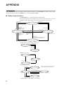
■ Display mode transitions • • • • • • • • • • • • • • • • • • • • • • • • • • • • • • • • • • • • • • • • • • • • • • • 39
■ Display functions • • • • • • • • • • • • • • • • • • • • • • • • • • • • • • • • • • • • • • • • • • • • • • • • • • • • • • 40
■ Names and functions of operator panel components • • • • • • • • • • • • • • • • • • 42
v
Conventions Used in This Manual
The following conventions are used in this manual:
Handling Precautions:
Handling Precautions indicate items that the user should pay attention to
when handling the AUR450C.
Note:
:
(1), (2), (3):
Notes indicate information that might benefit the user.
This indicates the item or page that the user is requested to refer to.
Numbers within parentheses indicate steps in a sequence or parts of an
explanation.
vi
Chapter 1.
OVERVIEW
Since the AUR450C is equipped with RS-485 communications capabilities, communications with a master station
such as a PC or EST Smart Terminal are available using a user-prepared program. The communications protocol is
CPL (Controller Peripheral Link: Yamatake’s host communications protocol).
For example, with a PC as a master station, and with either RS-232C or RS-485, the AUR450C’s operating status
can be monitored or its data can be cleared using the CPL communications protocol.
■ Features
The AUR450C’s communications functions include the following features:
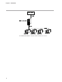
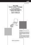
• Up to 15 AUR450C units can be connected to a single master station acting as a
master station. The CMC10B communications converter (sold separately) is necessary to connect 16 units or more.
• Connection to a master station having an RS-232C interface is also possible,
using the CMC10L communications controller (sold separately). The CMC10L
converts between RS-232C and RS-485 communications.
• Transmission speed up to 19200bps.
• Random access commands are available in addition to continuous access commands. Parameters at addresses separated by a single command can be read or
written.
■ Communications functions
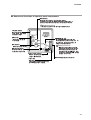
The AUR450C has 2 communications ports.
One is for host communications (RS-485) and the other is for loader communications.
Connect to the RS-485 connector on the front panel for host communications, and
to the loader jack for loader communications.
Host communications are performed with fixed wiring of the equipment, and are
used to monitor the operating status of multiple AUR450C units. Loader communications use a dedicated cable to connect with a PC.
Loader communications are useful for data analysis at the work site when equipment maintenance is performed.
This manual describes host communications.
In the RS-485 system, up to 15 units can be connected with one master station. The
station address is used to identify ontroller for communication.
When the following procedure is completed during communication, various data
for the controller can be read or written:
1. The master station transmits a request message to the slave station.
2. The master station receives a response message from the slave station.
• The commands from master station to slave station are classified into two types;
read and write.
• The type of read/write data can be selected by data address.
1
Chapter 1. OVERVIEW
"
(
$
#
"'
!" # $%
& "
#
'
$
#
"'
!" # $%
& "
#
'
$
#
"'
!" # $%
& "
#
'
$
#
"'
!" # $%
& "
The CMC10L001A000 is Yamatake's RS-232C/RS-485 converter.
2
#
'
Chapter 2.
WIRING
■ RS-485 connections
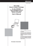
RS-485 communications use a 3-wire system.
Connect as follows using the RS-485 connector of the AUR450C:
Compatible connectors: Phoenix Contact
Model No. MSTB2.5/3-STF-5.08
Yamatake model No. 81446848-001 (1 unit)
IMPORTANT Terminating resistor
• Do not connect any terminating resistor to both ends of the transmission
line. Doing so might cause the communication failure.
• Even though any units requiring the terminating resistor to exist in the
transmossion line, do not connect any terminating resistor.
Handling Precautions
• Use a twisted shielded pair cable for RS-485 communications.
• Ground shielded wire to one point on one side of the cable.
• Wire the connections marked with an asterisk (*) externally, when 5-wire
system .
For connection method details, refer to;
AUR400C/450C Flame Safeguard Control Dynamic Self Check Burner
Controller User's Manual, No. CP-SP-1196E.
■ Loader connections
When the Smart Loader Package (simply called “SLP” from here on) is used,
connect from the loader jack of the AUR450C to a PC with the dedicated cable.
Note
• For SLP operation details, refer to:
SLP-A45 Smart Loader Package for the AUR450C Flame Safeguard
Control Dynamic Self Check Burner Controller User's Manual, No.CPSP-1187E.
3
Chapter 3.
COMMUNICATIONS SETTINGS
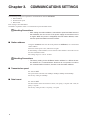
The following settings are required for communications with the AUR450C:
1. Station address
2. Transmission speed
3. Data format
Each setting is described below.
The SLP is required in order to set transmission speed and data format.
Handling Precautions
• After setting the station address, transmission speed and data format of
the AUR450C, be sure to turn off its power supply once and then turn it
on again. When the power is resupplied, the new station address, transmission speed and data format are in effect.
■ Station address
Using the ADDRESS switch on the front panel of the AUR450C, set to the desired
station address.
Then turn off the power once, and turn it on again.
In determining a station address, be sure that the same number is not used twice on
the same transmission line.
The setting range is 1 to F for 15 units.
Handling Precautions
• The factory setting for the AUR450C station address is 0. When the station address is 0, communications functions do not operate. In order to
use communications functions, be sure to set the station address.
■ Transmission speed
Set with the SLP.
The speed can be selected from 2400bps, 4800bps, 9600bps and 19200bps.
The factory setting is 19200bps.
■ Data format
Set with the SLP.
The data format can be selected from “8 bits, even parity, 1 stop bit” and “7 bits, no
parity, 2 stop bit.”
The factory setting is 8 bits, even parity, 1 stop bit.
4
Chapter 4.
4 - 1
COMMUNICATIONS
Outline of Communications
■ Communications procedures
The following is a simple breakdown of the communication procedure:
1. The master station transmits an instruction message to a slave station to specify
a station for communication.
2. The slave station processes the instruction message, and executes read and write
operations.
3. The slave station transmits a response message according to the contents of processing.
4. The master station receives the response message and executes processing.
■ Message structure
The following describes the message structure:
Messages are broadly classified into two layers: the data link layer and the application layer.
• Data link layer
This layer contains the basic information required for communications, such
as the destination of the instruction message and the checksum information for
the message.
• Application layer
Data is read and written in this layer. The content of the layer varies according
to the purpose of the message.
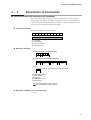
Messages are composed of 9 parts from (1) to (9) as shown in the figure below.
The command (details sent from the master station) and the response (details
returned from the slave station) are stored in the application layer.
02H
30H 30H 58H
STX
0
0
Data link layer
X
Application layer
03H
0DH 0AH
ETX
CR LF
Data link layer
1 frame
ETX(command/end of response)
STX (beginning of a message)
Checksum
Station address
CR (delimiter)
Sub-address (Fixed 00)
LF (delimiter)
Device code
Instruction message=command Response message=response
■ Data link layer
● Outline
The data link layer has a fixed length. Generally the position of each data item and
the number of its characters are fixed, but from ETX onwards the data positions
shift according to the number of characters in the application layer.
5
Chapter 4. COMMUNICATIONS
● Response start conditions
The AUR450C (slave station) sends a response only when the message structures
(station address, sub-address, checksum and message length of a single frame in
the data link layer) are all correct. If even one of these is incorrect, the AUR450C
does not send a response, and waits for new STX.
● List of data link layer data definitions
The following list shows the definitions for data in the data link layer:
Data name
Character code
Number of
bytes
Description
STX
02H
1
Begining of message
Station address
Hexadecimal 00 to 0FH
2
Identification of device
to communicate with
Sub-address
Displayed as hexadecimal
character codes
2
Fixed at 00
Device code
"X" (58H) or "x" (78H)
1
Device type
ETX
03H
1
End of the application
layer
Checksum
Displayed as 2-digit hexadecimal
character codes from 00H to FFH
2
Checksum of message
CR
0DH
1
End of message (1)
LF
0AH
1
End of message (2)
● Description of data link layer
• STX(02H)
When STX is received, the AUR450C concludes that an instruction message
has begun. Therefore, it returns to the initial state from whatever reception state
it was in, and processing is started taking STX as the first character received.
The purpose of this is to enable the device to recover and respond to the next
correct message (e.g. a RETRY message) from the master station in the event
that noise, for example, causes an error in the previously sent message.
• Station address
When the AUR450C receives instruction messages from the master station, it
creates response messages only when the station addressed is itself. The station
address in instruction messages is expressed as two-digit hexadecimal
characters.
The station address is set by the ADDRESS switch, which has a range of 0 to F.
When connecting 16 units or more, the CMC10B communications controller
(sold separately) is required.
When the station address is set to 0 (30H 30H), the AUR450C does not
respond even if the message is addressed to 30H 30H.
When replying, the slave station returns to the same station address that was
received.
• Sub-address
The AUR450C does not use sub-address.
For this reason, it returns "00" as the sub-address in response messages.
6
Chapter 4. COMMUNICATIONS
• Device code
The device code is either X (58H) or x (78H). This code is fixed for each device
series, so a different character cannot be used. When replying the AUR450C
returns the same device code that was received. It may be convenient to use X
(58H) first, and then use x (78H) to differentiate a resent message.
• ETX (03H)
ETX indicates the end of the application layer.
• Checksum
This value is for checking whether or not noise or other interference has
changed the message content during communications. The checksum is
expressed as a two-character hexadecimal number.
• How to calculate a checksum
(1) Add the character codes in the message from STX through ETX byte by
byte.
(2) Take the 2's complement of the low-order byte of the addition result.
(3) Convert the obtained 2's complement to a two-byte ASCII code.
Example)
The sample message below is used to illustrate the calculation.
Station address: 10 (0AH)
Sub-address: 00 (fixed)
Device code: X (58H)
02H 30H 41H 30H 30H 58H 52H 53H 2CH 31H 30H 30H 31H 57H 2CH 32H 03H 38H 41H 0DH 0AH
STX 0
A
0
0
X
R
S
,
1
0
0
1
W
,
2 ETX 8
A
CR LF
1. Add the character codes from STX to ETX byte by byte. The lower-order one
byte of the calculation result is 76H.
2. The result of two's complement addition is 8AH.
3. Convert into character codes and use as the checksum value. The result is 8A
(38H and 41H).
Handling Precautions
• Although the checksum of an instruction message can be omitted, in
this case a checksum is not contained in the response. In order to
ensure correct transmission of messages, do not omit the checksum.
• CR/LF
This indicates the end of the message. After LF is received, the processing of
the received message starts immediately.
7
Chapter 4. COMMUNICATIONS
■ Application layer
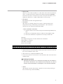
The table below shows the composition of the application layer.
Item
Command
Description
"RS" (Continuous data read command for decimal numerals)
"WS" (Continuous data write command for decimal numerals)
"RD" (Continuous data read command for hexadecimal numerals)
"WD" (Continuous data write command for hexadecimal numerals)
"RU" (Random data read command for hexadecimal numerals)
"WU" (Random data write command for hexadecimal numerals)
Data delimiter
RS, WS:
"," (comma)
RD, WD, RU, WU: None
Word address
RS, WS:
"501W", etc.
RD, WD, RU, WU: "01F5", etc.
Read numeric data
Numeric characters expressed as "1" for example.
Write numeric data
RS, WS:
Numeric characters expressed as "100" for example.
RD, WD, RU, WU: Numeric characters expressed in hexadecimal as
"0064" for example.
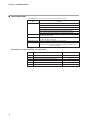
● Number of words accessible in a single frame
Type
8
Description of command
Number of words
RS
Read command for decimal numerals
16
WS
Write command for decimal numerals
16
RD
Read command for hexadecimal numerals
32
WD
Write command for hexadecimal numerals
32
RU
Random read command for hexadecimal numerals
16
WU
Random write command for hexadecimal numerals
16
Chapter 4. COMMUNICATIONS
4 - 2
Description of Commands
■ Continuous data read command (RS command)
This command reads the content of continuous data addresses starting with the
specified data start address. The address designation can be an actual address or a
virtual address. This command reads the contents of continuous addresses in one
message from a designated read data start address.
● Instruction message
Example of reading the present sequence.
R
S
(1)
,
(2)
1
0
0
(3)
1
W
,
1
(2) (4)
Application layer
(1) Command
(2) Data delimiter
(3) Data start address
(4) Read data count
● Response message
Normal (reading of single data item)
0 0 ,
(1) (2)
(3)
Normal (reading of multiple data items)
0 0 ,
(1) (2)
,
(3)
(2)
,
(4)
(2)
(5)
Error
X X
The termination code (error) is entered at XX.
(1)
(1) Termination codes*
(2) Data delimiter
(3) Data item 1
(4) Data item 2 to (n-1)
(5) Data item (n)
*For details of termination codes, refer to:
4-4, "Termination Codes" (page 16).
● Maximum read data count in one message
16 words
9
Chapter 4. COMMUNICATIONS
■ Continuous data write command (WS command)
This command writes the content of continuous data addresses starting with the
specified data start address.
● Instruction message
Example specifying a green light for flame voltage level of 3V and red light for 2V.
W
S
(1)
,
(2)
3
0
0
(3)
0
W
,
(2)
1
,
(4) (2)
0
2
(5)
(1) Command
(2) Data delimiter
(3) Write start address
(4) Write data (1st word)
(5) Write data (2nd word)
● Response message
Normal
0 0
(1)
Error/alarm
X X
The termination code (error/alarm) is entered at XX.
(1)
(1) Termination codes*
*For details of termination codes, refer to:
4-4, "Termination Codes" (page 16).
● Maximum write data count in one message
16 words
10
Chapter 4. COMMUNICATIONS
■ Fixed length continuous data read command (RD command)
RD is a command to read continuous data in two-byte units. It is suitable for
handling data in ladder programs sent by PLC communications, as the data is of a
fixed length. The data start address is expressed as a hexadecimal number of four
characters ("digits"). The number of data items is also expressed as four digits,
and data is expressed as 4n (n is a positive integer) hexadecimal digits.
● Instruction message
The read data start address (four hexadecimal digits) and the read data count (four
hexadecimal digits) are sent.
R D
(1)
(2)
(3)
(1) Command
(2) Data start address
(3) Read data count
● Response message
If the message is received successfully, the normal termination code (two decimal
digits) is returned along with the read data count (four hexadecimal digits times the
number of items read) specified by the command. If the message was not received
successfully, an abnormal termination code (two decimal digits) is returned without
the read data appended.
Normal (reading of single data item)
0 0
(1)
(2)
Normal (reading of multiple data items)
0 0
(1)
(2)
(3)
(4)
Error
X X
The termination code (error) is entered at XX.
(1)
(1) Termination codes*
(2) Data item 1
(3) Data items 2 to (n-1)
(4) Data item n
*For details of codes, refer to:
4-4, "Termination Codes" (page 16).
● Maximum read data count in one message
32 words
11
Chapter 4. COMMUNICATIONS
■ Fixed length continuous data write command (WD command)
WD is a command to write continuous data in two-byte units. It is suitable for
handling data in ladder programs sent by PLC communications as the data is of a
fixed length. The data start address is expressed as four hexadecimal digits. The
data is expressed as 4n (n is a positive integer) hexadecimal digits.
● Instruction message
The write data start address (four hexadecimal digits) and the write data count (4n
hexadecimal digits) are sent (n being the number of write data items).
● Response message
Writing of a single data item
W D
(1)
(2)
(3)
Writing of multiple data items
W D
(1)
(2)
(3)
(4)
(5)
(1) Command
(2) Data start address
(3) Data item 1
(4) Data items 2 to (n-1)
(5) Data item n
If writing is successful, the normal termination code (two decimal digits) is
returned. If only a part of the data is written, a warning termination code (two
decimal digits) is returned. If the data is not written at all, an abnormal
termination code (two decimal digits) is returned.
• Normal
0 0
(1)
• Error/alarm
X X
The termination code (error/alarm) is entered at XX.
(1)
(1) Termination codes*
*For details of codes, refer to:
4-4, "Termination Codes" (page 16).
● Maximum write data count in one message
32 words
12
Chapter 4. COMMUNICATIONS
■ Fixed length random data read command (RU command)
This command reads random (non-continuous) data in two-byte units.
● Instruction message
The data addresses (four hexadecimal digits) of the data to be read are sent in the
specified order.
R U 0 0
(1)
(2)
(3)
(4)
(5)
(1) Command
(2) Sub-command: fixed at 00.
(3) Data address 1
(4) Data addresses 2 to (n-1)
(5) Data address (n)
● Response message
If the message is received successfully, the normal termination code (two decimal
digits) is returned along with the read data count (four hexadecimal digits times
the number of data items) specified by the command. If the message was not
received successfully, an abnormal termination code (two decimal digits) is
returned without the read data appended.
Normal
0 0
(1)
(2)
(3)
(4)
Error
X X
The termination code (error) is entered at XX.
(1)
(1) Termination codes*
(2) Data item 1
(3) Data items 2 to (n-1)
(4) Data item n
*For details of codes, refer to:
4-4, "Termination Codes" (page 16).
● Maximum read data count in one message
16 words
13
Chapter 4. COMMUNICATIONS
■ Fixed length random data write command (WU command)
This command writes data to random (non-continuous) addresses in two-byte
units. Data is expressed as four hexadecimal digits.
● Instruction message
Data is sent such that the address (four hexadecimal digits) of the data to be
written and the data (four hexadecimal digits) form a pair.
"
#
! " # ● Response message
If writing is successful, the normal termination code (two decimal digits) is
returned. If only part of the data is written, and the remaining data is not written, a
warning termination code (two decimal digits) is returned. If none of the data is
written, an abnormal termination code (two decimal digits) is returned.
Normal
0 0
(1)
Error/alarm
X X
The termination code (error/alarm) is entered at XX.
(1)
(1) Termination codes*
*For details of codes, refer to:
4-4, "Termination Codes" (page 16).
● Maximum write data count in one message
16 words
14
Chapter 4. COMMUNICATIONS
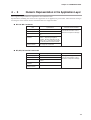
4 - 3
Numeric Representation in the Application Layer
Zero-suppressed representation is required for each numerical value.
Specifications, including the case that zero suppression is not applied, are given below. All instruction messages
involving the master station must be transmitted with zero-suppressed data.
● RS and WS commands
Item
Specifications
Unnecessary space
Cannot be used.
Unnecessary zero
Cannot be used.
Numerical value = zero
Cannot be omitted. Be sure to use
"0"
Other unnecessary
characters
Numerical values may be prefixed
with a "-" expressing a negative
number. No other character may be
used. The "+" sign must not be used
to indicate positive numerical values.
Range of available
numerical values
-32768 to +32767. Values outside of
this range are not allowed.
Treatment of Abnormalities
Message processing is aborted and
an abnormal termination code is
returned as a response message.
● RD, WD, RU and WU commands
Item
Specifications
Unnecessary space
Cannot be used.
Unnecessary zero
Cannot be used.
Numerical value = zero
Cannot be omitted. Be sure to use
"0000"
Other unnecessary
characters
Cannot be used.
Range of available
numerical values
0000H to FFFFH
Treatment of Abnormalities
Message processing is aborted and
an abnormal termination code is
returned as a response message.
15
Chapter 4. COMMUNICATIONS
4 - 4
Status Codes
The status code must be returned in a response message.
16
Status
code
Type
Description
00
Normal
99
Error
Undefined command
22
Alarm
23
Alarm
40
Error
The value of the written data is out of
the specified range.
Writing disabled due to instrument
settings, instrument external
conditions, etc.
Read data count error
41
Error
• Data address is out of range.
• Conversion error
• Outside of the range of -32768 to
+32767
42
Alarm
• Value of data is out of range.
• Data error
• Data length exceeds one word.
Normal termination
Treatment of Abnormalities
All processing was completed
normally.
Only the termination code is
returned and message processing
is not performed.
Processing continues except for
the data address concerned
Processing continues except for
the data address concerned.
Example
AA,1001W,1
RX03E80001
WS,2001W,3000
Only the termination code is
returned and message processing
is not performed.
Only the termination code is
returned and message processing
is not performed.
RS,1001W,A
RD03E9000Z
Processing is performed up to the
data address concerned; the
succeeding processing is not
performed.
WS,2001W,100,XXX
WS,2001W,100000
WD03E900010XXX
RS,100000W,1
WD0XXX0001
Chapter 4. COMMUNICATIONS
4 - 5
Timing Specifications
■ Timing specifications for instruction message and response message
The obligatory instructions below concern the timing of instruction message
transmission from the master station and response message transmission from the
slave station.
● Response monitor time
The maximum time between the end of the instruction message transmission by
the master station and the start of reception of the response message from the slave
station is two seconds [(1) in the figure below]. Therefore the response monitor
time should be set to two seconds.
Resend the instruction message if a response time-out occurs.
● Transmission start time
A wait time of 10ms is required before the master station starts to transmit the next
instruction message (to the same slave station or a different slave station) after
reception of a response message has ended [(2) in the figure below].
RS-485 3-wire system
Transmission line
(1)
(2)
Instruction
message
Response
message
Instruction
message
Response
message
(1) End of master station transmission transmission start time of slave station = max. 2000ms
(2) End of slave station transmission transmission start time of master station = min. 10ms
■ RS-485 driver control timing specifications
When the transmission/reception on the RS-485 3-wire system is directly
controlled by the master station, care should be paid to the following timing:
(1)
Master station
driver control
(Enabled)
Transmission
line
Slave station
driver control
(4)
(Disabled)
Valid
data
Valid
data
(instruction
message)
(response
message)
(Enabled)
(Disabled)
(2)
End of master
station transmission
(3)
End of slave
station transmission
(1) End of master station transmission - time until driver disabled = max. 500 s
(2) End of slave station reception - time until driver enabled = min. 1ms
(3) End of slave station transmission - time until driver disabled = max. 10ms
(4) End of master station reception - time until driver enabled = min. 10ms
17
Chapter 5.
COMMUNICATIONS DATA
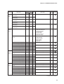
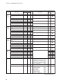
■ Memory map (communications data table)
Data type
Maintenance
data
Time/
count
data
Item name
Address
Write
Initial
value
Data range
Decimal
Hex.
Present sequence
1000W
03E8
X
0:
1:
2:
3:
4:
5:
6:
Standby
Start check (P1)
Ignition trial (P2)
Pilot only (P3)
Main trial (P4)
RUN (P5)
Alarm
—
Alarm occurrence status
1001W
03E9
X
0:
1:
2:
3:
4:
5:
6:
No alarm
Start check alarm (E0)
Interlock alarm (E1)
False flame (E2)
UV alarm (E3)
Ignition failure (E4)
Flame failure (E5)
—
Event occurrence status
1002W
03EA
X
Bit 0: Ignition delay (A1)
Bit 1: Shutter cycle count upper setting
value (A2)
Bit 2: Shutter cycle count lower setting
value (A3)
Bit 3: Operation time upper setting
value (A4)
Bit 4: Combustion time upper setting
value (A5)
Bit 5: Combustion count upper setting
value (A6)
Bit 6: Flame voltage upper setting
value (A7)
Bit 7: Flame voltage lower setting
value (A8)
—
Flame voltage
1003W
03EB
X
0 to 50
—
Flame voltage (maximum)
1004W
03EC
X
0 to 50
—
Flame voltage (minimum)
1005W
03ED
X
0 to 50
—
Average flame voltage (1s)
1006W
03EE
X
0 to 50
—
Average flame voltage (1min)
1007W
03EF
X
0 to 50
—
Shutter-open/closed cycle period
1016W
03F8
X
0 to 10000
—
Shutter-open time
1017W
03F9
X
0 to 5000
—
Shutter-closed time
1018W
03FA
X
0 to 5000
—
Shutter cycle count
1019W
03FB
X
0 to 255
—
Ignition delay time
1020W
03FC
X
0 to 100
999 (ignition failure)
—
Lockout occurrence status (bit)
1021W
03FD
X
Bit 0: Start check alarm
Bit 1: Interlock alarm
Bit 2: False flame
Bit 3: UV alarm
Bit 4: Ignition failure
Bit 5: Flame failure
Bit 6: Undefined
Bit 7: Undefined
—
Operation time (lower bytes)
1100W
044C
X
0 to 99999
—
Operation time (upper bytes)
1101W
044D
X
0 to 99999
—
0 to 99999
—
Combustion time (lower bytes)
1102W
044E
X
Combustion time (upper bytes)
1103W
044F
X
Combustion count (lower bytes)
1104W
0450
X
Combustion count (upper bytes)
1105W
0451
X
Remarks
Continue on next page.
18
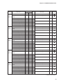
Chapter 5. COMMUNICATIONS DATA
Data type
Time/
count
data
Alarm
history
data 1
Alarm
history
data 2
Alarm
history
data 3
Item name
Address
Write
Decimal
Hex.
Operation time for event
(lower bytes)
1106W
0452
X
Operation time for event
(upper bytes)
1107W
0453
X
Combustion time for event
(lower bytes)
1108W
0454
X
Combustion time for event
(upper bytes)
1109W
0455
X
Combustion count for event
(lower bytes)
1110W
0456
X
Combustion count for event
(upper bytes)
1111W
0457
X
Alarm code 1
2000W
07D0
Sequence code when lockout
occurs
2001W
Operation time ( lower bytes)
2002W
Data range
Initial
value
0 to 99999
—
0 to 99999
—
0 to 99999
—
X
0:
1:
2:
3:
4:
5:
6:
No alarm
Start check alarm (E0)
Interlock alarm (E1)
False flame (E2)
UV alarm (E3)
Ignition failure (E4)
Flame failure (E5)
—
07D1
X
0:
1:
2:
3:
4:
5:
No alarm
Start check (P1)
Ignition trial (P2)
Pilot only (P3)
Main trial (P4)
RUN (P5)
—
07D2
X
0 to 99999
—
0 to 99999
—
0 to 99999
—
Operation time (upper bytes)
2003W
07D3
X
Combustion time (lower bytes)
2004W
07D4
X
Combustion time (upper bytes)
2005W
07D5
X
Combustion count (lower bytes)
2006W
07D6
X
Combustion count (upper bytes)
2007W
07D7
X
Alarm code 2
2008W
07D8
X
Same as alarm history data 1
—
Sequence code when lockout
occurs
2009W
07D9
X
Same as alarm history data 1
—
Operation time ( lower bytes)
2010W
07DA
X
0 to 99999
—
Operation time (upper bytes)
2011W
07DB
X
Combustion time ( lower bytes)
2012W
07DC
X
0 to 99999
—
Combustion time (upper bytes)
2013W
07DD
X
Combustion count ( lower bytes)
2014W
07DE
X
0 to 99999
—
Combustion count (upper bytes)
2015W
07DF
X
Alarm code 3
2016W
07E0
X
Same as alarm history data 1
—
Sequence code when lockout
occurs
2017W
07E1
X
Same as alarm history data 1
—
Operation time( lower bytes)
2018W
07E2
X
0 to 99999
—
Operation time (upper bytes)
2019W
07E3
X
Combustion time ( lower bytes)
2020W
07E4
X
0 to 99999
—
Combustion time (upper bytes)
2021W
07E5
X
Combustion count ( lower bytes)
2022W
07E6
X
0 to 99999
—
Combustion count (upper bytes)
2023W
07E7
X
Remarks
Continue on next page.
19
Chapter 5. COMMUNICATIONS DATA
Data type
Alarm
history
data 4
Alarm
history
data 5
Alarm
history
data 6
Alarm
history
data 7
Alarm
history
data 8
Item name
Address
Decimal
Hex.
Write
Data range
Initial
value
Alarm code 4
2024W
07E8
X
Same as alarm history data 1
—
Sequence code when lockout
occurs
2025W
07E9
X
Same as alarm history data 1
—
Operation time ( lower bytes)
2026W
07EA
X
0 to 99999
—
0 to 99999
—
0 to 99999
—
Operation time (upper bytes)
2027W
07EB
X
Combustion time ( lower bytes)
2028W
07EC
X
Combustion time (upper bytes)
2029W
07ED
X
Combustion count ( lower bytes)
2030W
07EE
X
Combustion count (upper bytes)
2031W
07EF
X
Alarm code 5
2032W
07F0
X
Same as alarm history data 1
—
Sequence code when lockout
occurs
2033W
07F1
X
Same as alarm history data 1
—
Operation time ( lower bytes)
2034W
07F2
X
0 to 99999
—
Operation time (upper bytes)
2035W
07F3
X
Combustion time ( lower bytes)
2036W
07F4
X
0 to 99999
—
Combustion time (upper bytes)
2037W
07F5
X
Combustion count ( lower bytes)
2038W
07F6
X
0 to 99999
—
Combustion count (upper bytes)
2039W
07F7
X
Alarm code 6
2040W
07F8
X
Same as alarm history data 1
—
Sequence code when lockout
occurs
2041W
07F9
X
Same as alarm history data 1
—
Operation time ( lower bytes)
2042W
07FA
X
0 to 99999
—
0 to 99999
—
0 to 99999
—
Operation time (upper bytes)
2043W
07FB
X
Combustion time ( lower bytes)
2044W
07FC
X
Combustion time (upper bytes)
2045W
07FD
X
Combustion count ( lower bytes)
2046W
07FE
X
X
Combustion count (upper bytes)
2047W
07FF
Alarm code 7
2048W
0800
X
Same as alarm history data 1
—
Sequence code when lockout
occurs
2049W
0801
X
Same as alarm history data 1
—
Operation time ( lower bytes)
2050W
0802
X
0 to 99999
—
0 to 99999
—
0 to 99999
—
Operation time (upper bytes)
2051W
0803
X
Combustion time ( lower bytes)
2052W
0804
X
Combustion time (upper bytes)
2053W
0805
X
Combustion count ( lower bytes)
2054W
0806
X
Combustion count (upper bytes)
2055W
0807
X
Alarm code 8
2056W
0808
X
Same as alarm history data 1
—
Sequence code when lockout
occurs
2057W
0809
X
Same as alarm history data 1
—
Operation time ( lower bytes)
2058W
080A
X
0 to 99999
—
Operation time (upper bytes)
2059W
080B
X
Combustion time ( lower bytes)
2060W
080C
X
0 to 99999
—
Combustion time (upper bytes)
2061W
080D
X
Combustion count ( lower bytes)
2062W
080E
X
0 to 99999
—
Combustion count (upper bytes)
2063W
080F
X
Remarks
Continue on next page.
20
Chapter 5. COMMUNICATIONS DATA
Data type
Alarm
history
data 9
Alarm
history
data 10
Alarm
history
data 11
Alarm
history
data 12
Alarm
history
data 13
Item name
Address
Decimal
Hex.
Write
Data range
Initial
value
Alarm code 9
2064W
0810
X
Same as alarm history data 1
—
Sequence code when lockout
occurs
2065W
0811
X
Same as alarm history data 1
—
Operation time ( lower bytes)
2066W
0812
X
0 to 99999
—
0 to 99999
—
0 to 99999
—
Operation time (upper bytes)
2067W
0813
X
Combustion time ( lower bytes)
2068W
0814
X
Combustion time (upper bytes)
2069W
0815
X
Combustion count ( lower bytes)
2070W
0816
X
Combustion count (upper bytes)
2071W
0817
X
Alarm code 10
2072W
0818
X
Same as alarm history data 1
—
Sequence code when lockout
occurs
2073W
0819
X
Same as alarm history data 1
—
Operation time ( lower bytes)
2074W
081A
X
0 to 99999
—
Operation time (upper bytes)
2075W
081B
X
Combustion time ( lower bytes)
2076W
081C
X
0 to 99999
—
Combustion time (upper bytes)
2077W
081D
X
Combustion count ( lower bytes)
2078W
081E
X
0 to 99999
—
Combustion count (upper bytes)
2079W
081F
X
Alarm code 11
2080W
0820
X
Same as alarm history data 1
—
Sequence code when lockout
occurs
2081W
0821
X
Same as alarm history data 1
—
Operation time ( lower bytes)
2082W
0822
X
0 to 99999
—
0 to 99999
—
0 to 99999
—
Operation time (upper bytes)
2083W
0823
X
Combustion time ( lower bytes)
2084W
0824
X
Combustion time (upper bytes)
2085W
0825
X
Combustion count ( lower bytes)
2086W
0826
X
X
Combustion count (upper bytes)
2087W
0827
Alarm code 12
2088W
0828
X
Same as alarm history data 1
—
Sequence code when lockout
occurs
2089W
0829
X
Same as alarm history data 1
—
Operation time ( lower bytes)
2090W
082A
X
0 to 99999
—
0 to 99999
—
0 to 99999
—
Operation time (upper bytes)
2091W
082B
X
Combustion time ( lower bytes)
2092W
082C
X
Combustion time (upper bytes)
2093W
082D
X
Combustion count ( lower bytes)
2094W
082E
X
Combustion count (upper bytes)
2095W
082F
X
Alarm code 13
2096W
0830
X
Same as alarm history data 1
—
Sequence code when lockout
occurs
2097W
0831
X
Same as alarm history data 1
—
Operation time ( lower bytes)
2098W
0832
X
0 to 99999
—
Operation time (upper bytes)
2099W
0833
X
Combustion time ( lower bytes)
2100W
0834
X
0 to 99999
—
Combustion time (upper bytes)
2101W
0835
X
Combustion count ( lower bytes)
2102W
0836
X
0 to 99999
—
Combustion count (upper bytes)
2103W
0837
X
Remarks
Continue on next page.
21
Chapter 5. COMMUNICATIONS DATA
Data type
Alarm
history
data 14
Alarm
history
data 15
Alarm
history
data 16
Alarm
count
Initilization
Item name
Address
Decimal
Hex.
Write
Initial
value
Data range
Alarm code 14
2104W
0838
X
Same as alarm history data 1
—
Sequence code when lockout
occurs
2105W
0839
X
Same as alarm history data 1
—
Operation time ( lower bytes)
2106W
083A
X
0 to 99999
—
0 to 99999
—
0 to 99999
—
Operation time (upper bytes)
2107W
083B
X
Combustion time (lower bytes)
2108W
083C
X
Combustion time (upper bytes)
2109W
083D
X
Combustion count (lower bytes)
2110W
083E
X
Combustion count (upper bytes)
2111W
083F
X
Alarm code 15
2112W
0840
X
Same as alarm history data 1
—
Sequence code when lockout
occurs
2113W
0841
X
Same as alarm history data 1
—
Operation time (lower bytes)
2114W
0842
X
0 to 99999
—
Operation time (upper bytes)
2115W
0843
X
Combustion time (lower bytes)
2116W
0844
X
0 to 99999
—
Combustion time (upper bytes)
2117W
0845
X
Combustion count (lower bytes)
2118W
0846
X
0 to 99999
—
Combustion count (upper bytes)
2119W
0847
X
Alarm code 16
2120W
0848
X
Same as alarm history data 1
—
Sequence code when lockout
occurs
2121W
0849
X
Same as alarm history data 1
—
Operation time (lower bytes)
2122W
084A
X
0 to 99999
—
0 to 99999
—
0 to 99999
—
0 to 255
—
Operation time for event:
A5C1
Combustion time for event: A5C2
Combustion count for event: A5C3
Operation time for event, combustion
time for event, combustion count for
event — initialize all:
A5C4
—
Operation time (upper bytes)
2123W
084B
X
Combustion time (lower bytes)
2124W
084C
X
Combustion time (upper bytes)
2125W
084D
X
Combustion time (lower bytes)
2126W
084E
X
Combustion count (upper bytes)
2127W
084F
X
Start check alarm (E0) count
2500W
09C4
X
Interlock alarm (E1) count
2501W
09C5
X
False flame (E2) count
2502W
09C6
X
UV alarm (E3) count
2503W
09C7
X
Ignition failure (E4) count
2504W
09C8
X
Flame failure (E5) count
2505W
09C9
X
Event time/count initialization
3801W
0ED9
O
Alarm history 1 to 16 initilization
3802W
0EDA
O
Alarm count initialization
3803W
0EDB
O
E0 (Start check alarm):
E1 (Interlock alarm):
E2 (False flame):
E3 (UV alarm):
E4 (Ignition failure):
E5 (Flame failure):
E0 to E5 — initialize all:
AC53
—
AC51
AC52
AC53
AC54
AC55
AC56
AC59
—
Remarks
Continue on next page.
22
Chapter 5. COMMUNICATIONS DATA
Data type
Event
FLAME
LED
Item name
Address
Write
Initial
value
Data range
Decimal
Hex.
Clear event
3804W
0EDC
O
Clear A1:
Clear A2:
Clear A3:
Clear A4:
Clear A5:
Clear A6:
Clear A7:
Clear A8:
Clear all from A1 to A8:
Ignition delay
7040W
1B80
O
0: Unselected, 1: Selected
0
Shutter cycle count upper setting
value
7041W
1B81
O
0: Unselected, 1: Selected
0
Shutter cycle count lower setting
value
7042W
1B82
O
0: Unselected, 1: Selected
0
Operation time for event upper
setting value
7043W
1B83
O
0: Unselected, 1: Selected
0
Combustion time for event upper
setting value
7044W
1B84
O
0: Unselected, 1: Selected
0
Combustion count for event upper 7045W
setting value
1B85
O
0: Unselected, 1: Selected
0
CA51
CA52
CA53
CA54
CA55
CA56
CA57
CA58s
CA59
Remarks
—
Flame voltage upper setting value 7046W
1B86
O
0: Unselected, 1: Selected
0
Flame voltage lower setting value 7047W
1B87
O
0: Unselected, 1: Selected
0
Ignition delay time setting
7048W
1B88
O
0 to 100
100
Shutter cycle count upper setting
value
7049W
1B89
O
0 to 255
255
Shutter cycle count lower setting
value
7050W
1B8A
O
0 to 255
0
Operation time for event upper
setting value (lower bytes) *
7051W
1B8B
O
0 to 99999
25000
Operation time for event upper
setting value (upper bytes) *
7052W
1B8C
O
Combustion time for event upper
setting value (lower bytes) *
7053W
1B8D
O
0 to 99999
25000
Combustion time for event upper
setting value (upper bytes) *
7054W
1B8E
O
Combustion count for event upper 7055W
setting value (lower bytes)
1B8F
O
0 to 99999
99999
Combustion count for event upper 7056W
setting value (upper bytes)
1B90
O
Flame voltage upper setting value 7057W
time
1B91
O
0 to 255
255
Flame voltage upper setting value 7058W
1B92
O
0 to 50
50
Flame voltage lower setting value 7059W
time
1B93
O
0 to 255
255
Flame voltage lower setting value 7060W
1B94
O
0 to 50
0
Green FLAME LED light level
7070W
1B9E
O
0 to 50
25
Red FLAME LED light level
7071W
1B9F
O
0 to 50
15
Continue on next page.
23
Chapter 5. COMMUNICATIONS DATA
Data type
Address
Item name
Data range
Initial
value
Remarks
Hex.
8000W
1F40
O
0: Data length 8 bits, even parity,
1 stop bit
1: Data length 7 bits, no parity,
2 stop bits
0
Set with
the SLP
Transmission speed
8001W
1F41
O
0: 2400bps
1: 4800bps
2: 9600bps
3: 19200bps
3
Set with
the SLP
AUR memo and tab
8100W
1FA4
O
—
↓
↓
↓
↓
8159W
1FDF
O
—
RS-485 Data format
communications
settings
AUR
memo
Write
Decimal
↓
in the Remarks column denotes the data for backup.
O in the Write column means that writing from an external device is possible.
X means that writing from an external device is not possible.
* indicates that the WU command should be used when writing data.
Handling Precautions
• Data written to 7000W level addresses and 8000W level addresses is
saved in EEPROM. The number of times that EEPROM can be rewritten
is limited (100,000 operations). Accordingly, do not rewrite frequently.
● Writing data range
If the data to be written exceeds the range determined by parameters, it is not written, and an abnormal termination code is returned.
● Writing conditions
An abnormal termination code is also returned when writing is not performed for
other reasons.
■ Data backup
Data is saved to EEPROM.
Updating of data to EEPROM is performed in the following cases:
• When lockout occurs
• After every hour of operation
• When setup is changed by communications.
Data that is less than one hour old is maintained by a backup capacitor.
Handling Precautions
• If the backup time (4 to 12 hours under normal temperature and humidity)
is exceeded, operation time or combustion time data less than one hour
old may be lost.
• When the backup time is exceeded, combustion count data that has not
been saved to EEPROM may be lost.
• When it is necessary to clear trial operation data before delivering the
equipment to the user, clear the trial data first and then store the formal
operation data.
24
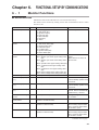
Chapter 6.
6 - 1
FUNCTIONAL SETUP BY COMMUNICATIONS
Monitor Functions
■ Maintenance data
Maintenance data in the table below is stored in internal memory.
The details can be checked by reading out the data at maintenance/check or when
lockout occurs.
Item
Address
Data range
Remarks
Present sequence
1000W
0:
1:
2:
3:
4:
5:
6:
Standby (--)
Start check (P1)
Ignition trial (P2)
Pilot only (P3)
Main trial (P4)
RUN (P5)
Alarm
Present sequence code
Alarm occurrence
status
1001W
0:
1:
2:
3:
4:
5:
6:
No alarm
Start check alarm (E0)
Interlock alarm (E1)
False flame (E2)
UV alarm (E3)
Ignition failure (E4)
Flame failure (E5)
Present alarm code
Event occurrence
status
1002W
Flame voltage
1003W
Bit 0: Ignition delay (A1)
Bit 1: Shutter cycle count upper setting value
(A2)
Bit 2: Shutter cycle count lower setting value
(A3)
Bit 3: Operation time upper setting value (A4)
Bit 4: Combustion time upper setting value
(A5)
Bit 5: Combustion count upper setting value
(A6)
Bit 6: Flame voltage upper setting value (A7)
Bit 7: Flame voltage lower setting value (A8)
0 to 50 (0.0 to 5.0V)
Present event occurrence
status.
When there is no event, all
bits are OFF.
Flame voltage (max.)
[*1]
1004W
0 to 50 (0.0 to 5.0V)
Maximum flame voltage.Data
is automatically updated every
5 seconds.
Flame voltage (min.)
[*1]
1005W
0 to 50 (0.0 to 5.0V)
Minimum flame voltage. Data
is automatically updated every
5 seconds.
Average flame voltage
(1s)
1006W
0 to 50 (0.0 to 5.0V)
Average flame voltage for 1
second. Data is automatically
updated every 1 second.
Average flame voltage
(1min)
1007W
0 to 50 (0.0 to 5.0V)
Moving-average flame voltage
for 1 minute.
Shutter-open/closed
cycle period
1016W
0 to 10000
(0.000 to 10.000 seconds)
Shutter-open/closed total time
Shutter-open time
1017W
0 to 5000
(0.000 to 5.000 seconds)
Shutter-open time.
Time counting stops at 5000
after 5 seconds elapse while
the shutter is open.
Shutter-closed time
1018W
0 to 5000
(0.000 to 5.000 seconds)
Shutter-closed time.
Time counting stops at 5000
after 5 seconds elapse while
the shutter is closed.
Present flame voltage
Continue on next page.
25
Chapter 6. FUNCTIONAL SETUP BY COMMUNICATIONS
Item
Address
Data range
Remarks
Average flame voltage
(1min)
1019W
0 to 255
(0 to 255 times)
Shutter cycle count.
Data is automatically updated
every 1 second.
Ignition delay time
[*2]
1020W
0 to 100 (0 to 10.0 seconds)
999 (ignition failure)
Time from ignition trial start to
ignition detection.
Lockout occurrence
status
1021W
Bit 0:
Bit 1:
Bit 2:
Bit 3:
Bit 4:
Bit 5:
Bit 6:
Bit 7:
Present alarm occurrence
status.
When there is no alarm, all
bits are OFF.
Start check alarm
Interlock alarm
False flame
UV alarm
Ignition failure
Flame failure
Undefined
Undefined
*1 The maximum and minimum value calculations are based on average flame
voltage for 1s.
The values within parentheses ( ) are in the actual unit.
*2 Ignition delay data is as shown below:
Status
Data
Ignition failure
999
Start contact is OFF during ignition trial operation.
0
Interlock is OFF during ignition trial operation, resulting in lockout.
0
Data is cleared at startup and changed to 0.
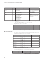
■ Time/count data
Time data and operation count data for the items shown in the table below are collected and recorded. Time/count is shown in 2 words.
Item
Address
Data range
Remarks
Operation time
1100W
1101W
0 to 99999h
Cumulative ON time
Combustion time
1102W
1103W
0 to 99999h
Cumulative RUN time
Combustion count
1104W
1105W
0 to 99999 times
Cumulative RUN count
Operation time
(for event)*
1106W
1107W
0 to 99999h
ON time
Combustion time
(for event)*
Combustion count
(for event)*
1108W
1109W
1110W
1111W
0 to 99999h
RUN time
0 to 99999 times
RUN count
* Data for events is cleared to 0 at event clear.
For example, an operation time of 76,543 is stored as shown below.
Operation time
Hexadecimal
Upper bytes (1101W)
Lower bytes (1100W)
76543
12AFF
1h (1)
2AFFh (11007)
Numbers in parentheses ( ) are decimal numbers.
26
Chapter 6. FUNCTIONAL SETUP BY COMMUNICATIONS
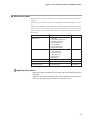
■ Alarm history data
When an alarm occurs, the data below is recorded in internal memory as alarm history data.
Data for the past 16 alarm occurrences, including the latest lockout data, is recorded.
Addresses are 2000W to 2127W. Each piece of alarm data is structured as 8 continuous “words.” Alarm history time/count data consists of 2 words, like the
time/count data of the previous item. The lower number of the address shows the
lower bytes.
Item
Data range
Remarks
Alarm code
0:
1:
2:
3:
4:
5:
6:
No alarm
Start check alarm (E0)
Interlock alarm (E1)
False flame (E2)
UV alarm (E3)
Ignition failure (E4)
Flame failure (E5)
Sequence code on lockout
0:
1:
2:
3:
4:
5:
No alarm
Start check (P1)
Ignition trial (P2)
Pilot only (P3)
Main trial (P4)
RUN (P5)
Operation time
0 to 99999h
2-word data
Combustion time
0 to 99999h
2-word data
Combustion count
0 to 99999 times
2-word data
Handling Precautions
• When more than 16 alarms have occurred, the oldest alarm history data
is deleted.
• If the data items from the alarm code to the combustion count all have a
value of 0, the alarm history data has not yet been set up.
27
Chapter 6. FUNCTIONAL SETUP BY COMMUNICATIONS
The relationship between alarm occurrence order and address is shown below.
Alarm occurrence order
Address
Alarm (1) (latest)
2000W to 2007W
2000W Alarm code
Alarm (2)
2008W to 2015W
2001W Sequence code on lockout
Alarm (3)
2016W to 2023W
2002W Operation time (lower bytes)
Alarm (4)
2024W to 2031W
2003W Operation time (upper bytes)
Alarm (5)
2032W to 2039W
2004W Operation time (lower bytes)
Alarm (6)
2040W to 2047W
2005W Operation time (upper bytes)
Alarm (7)
2048W to 2055W
2006W Operation time (lower bytes)
Alarm (8)
2056W to 2063W
2007W Operation time (upper bytes)
Alarm (9)
2064W to 2071W
Alarm (10)
2072W to 2079W
Alarm (11)
2080W to 2087W
Alarm (12)
2088W to 2095W
Alarm (13)
2096W to 2103W
Alarm (14)
2104W to 2111W
Alarm (15)
2112W to 2119W
Alarm (16)
2120W to 2127W
■ Alarm count
A count of each type of alarm is stored in internal memory.
Up to 255 occurrences are recorded for each.
Item
Address
Data range
Start check alarm (E0) count
2500W
0 to 255
Interlock alarm (E1) count
2501W
0 to 255
False flame (E2) count
2502W
0 to 255
UV alarm (E3) count
2503W
0 to 255
Ignition failure (E4) count
2504W
0 to 255
Flame failure (E5) count
2505W
0 to 255
Remarks
Count of up to 255
alarm ocurrences.
Alarms occurrences
over 255 are not
recorded.
■ AUR memo
Up to 120 ASCII characters, or 60 characters (2-byte code) can be recorded.
Addresses are the 60-words from 8100W to 8159W.
28
Chapter 6. FUNCTIONAL SETUP BY COMMUNICATIONS
6 - 2
Event Functions
■ Event item
The items below can be handled as events on the AUR450C.
Event item
Event No.
Summary
Ignition delay
A1
The time from ignition trial start to flame detection is measured as ignition
delay time. When it exceeds the set value, an event occurs.
Shutter cycle count upper
setting value
A2
When the shutter cycle count exceeds the set value, an event occurs.
Shutter cycle count lower
setting value
A3
When the shutter cycle count drops below the set value, an event occurs.
Operation time for event
upper setting value
A4
When the AUR450C operation time exceeds the set value, an event occurs.
Combustion time for event
setting value
A5
When the AUR450C combustion time exceeds the set value, an event upper
occurs.
Combustion count for
event upper setting value
A6
When the AUR450C combustion count exceeds the set value, an event
occurs.
Flame voltage upper
setting value
A7
When the AUR450C flame voltage has exceeded the set value during
RUN, and the response time has elapsed, an event occurs.
Flame voltage lower
setting value
A8
When AUR450C flame voltage has dropped below the set value during
RUN, and the response time has elapsed, an event occurs.
■ Using an event
The three steps below are required for an event function to operate.
(1) Select the event for use.
Determine the event for use from selection addresses 7040W to 7047W.
When “1” is written to an event selection address, the event can be selected.
(All items can also be selected as events.) Since the factory setting is “0”
(unselected), all events are initially unavailable.
(2) Set the event conditions.
The setting of conditions for each event is performed at addresses 7048W to
7060W. Choose the numeric value that will trigger the event, and write it to
the condition setting address.
Handling Precautions
• Be sure to select the event in selection addresses 7040W to 7047W
as described above in item (1). Writing a value to the condition setting
address alone is not sufficient for the event to occur.
(3) Event occurrence
When the conditions previously determined and set in item (2) are satisfied,
the event occurs.
When the event occurs, the EVENT LED lights up, and the relevant event
occurrence status bit (in 1002W) of the communications data is changed to
“1.” In addition, if the DISP switch is pressed when the EVENT LED is lit,
the event code is displayed on the 7-segment display.
Handling Precautions
• When the EVENT LED lights up while an alarm also occurs, the event
code cannot be displayed by pressing the DISP switch.
• When some events occur, the display shows event codes automatically in turn.
• An event, once it has occurred, will be held until it is cleared.
29
Chapter 6. FUNCTIONAL SETUP BY COMMUNICATIONS
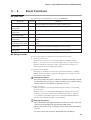
■ Details on event items
● Ignition delay (A1)
The AUR450C measures ignition delay time from begining the ignition trial time
to flame detection (K6 ON). When the ignition delay time exceeds the ignition
delay time setting limit, an event occurs. However, an event cannot be set for the
following cases:
• Ignition failure
• Error during ignition trial (interlock error, etc.)
• The start contact OFF during ignition trial
Item
Selection
Address
Content
7040W Ignition delay
Condition setting
7048W Ignition delay time setting
Measurement data 1020W Ignition delay time
Data range Factory setting
0: Unselected
1: Selected
0 to 100
0 to 100
0
100
-
Remarks
7048W, 1020W are enable
when 1:selected.
(10.0s)
999 (Ignition failure)
The factory setting number in parentheses ( ) is expressed in the actual data unit.
● Shutter cycle count upper setting value (A2)
The AUR450C measures the number of shutter cycles per minute. When this shutter cycle count exceeds the shutter cycle count upper setting value during combustion (operating sequence RUN), an event occurs. However, after beginning RUN,
the conditions for events are not judged for 2 minutes.
Item
Address
Content
Selection
7041W Shutter cycle count upper
setting value
Condition setting
7049W Shutter cycle count upper
setting value
Measurement data 1019W Shutter cycle count
Data range Factory setting
0: Unselected
1: Selected
0 to 255
0 to 255
0
255
Remarks
7049W, 1019W are enable
when 1:selected.
(255 times)
-
The factory setting number in parentheses ( ) is expressed in the actual data unit.
● Shutter cycle count lower setting value (A3)
The AUR450C measures the number of shutter cycles per minute. When this shutter cycle count drops below the shutter cycle count lower setting value during the
RUN period, an event occurs. However, after beginning RUN, the conditions for
events are not judged for 2 minutes.
Item
Selection
Address
Content
7042W Shutter cycle count lower
setting value
Condition setting
7050W Shutter cycle count lower
setting value
Measurement data 1019W Shutter cycle count
Data range Factory setting
0: Unselected
1: Selected
0 to 255
0
0 to 255
-
0
Remarks
7050W, 1019W are enable
when 1:selected.
(0 time)
The factory setting number in parentheses ( ) is expressed in the actual data unit.
30
Chapter 6. FUNCTIONAL SETUP BY COMMUNICATIONS
● Operation time for event upper setting value (A4)
The operating time of the AUR450C is measured as operation time for event.
When operation time for event exceeds the operation time for event setting value,
an event occurs.
Item
Selection
Address
Content
Data range Factory setting
7043W Operation time for event upper 0: Unselected
setting value
1: Selected
7051W Operation time for event upper 0 to 99999
setting value (lower bytes)
7052W Operation time for event upper
setting value (upper bytes)
Measurement data 1106W Operation time for event
0 to 99999
(lower bytes)
1107W Operation time for event
(upper bytes)
0
Remarks
7051W, 7052W, 1106W,
1107W are enable when
1:selected.
25000
Condition setting
-
Handling Precautions
• Use the WU command to write this data.
For example, the setup for an operation time for event upper setting value of 76,543
hours is as follows:
Operation time for event
upper setting value
76543
Hexadecimal
Upper bytes
(7052W)
Lower bytes
(7051W)
12AFF
1h (1)
2AFFh (11007)
The decimal equivalent is in parentheses ( ).
● Combustion time for event upper setting value (A5)
The combustion (RUN) time of the AUR450C is measured as combustion time for
event. When combustion time for event exceeds the combustion time for event setting value, an event occurs.
Item
Selection
Address
Content
7044W Combustion time for events
upper setting value
Data range Factory setting
0: Unselected
1: Selected
Condition setting
7053W Combustion time for event
0 to 99999
upper setting value (lower bytes)
7054W Combustion time for event
upper setting value (upper bytes)
Measurement data 1108W Combustion time for event
0 to 99999
(lower bytes)
1109W Combustion time for event
(upper bytes)
0
25000
Remarks
7053W, 7054W, 1108W,
1109W are enable when
1:selected.
(25000 h)
-
The factory setting number in parentheses ( ) is expressed in the actual data unit.
Handling Precautions
• Use the WU command to write this data.
For example, the combustion time for event upper setting value can be set to
76,543 hours as follows:
Combustion time for event
upper setting value
Hexadecimal
Upper bytes
(7052W)
Lower bytes
(7051W)
76543
12AFF
1h (1)
2AFFh (11007)
The decimal equivalent is in parentheses ( ).
31
Chapter 6. FUNCTIONAL SETUP BY COMMUNICATIONS
● Combustion count for event upper setting value (A6)
The combustion count (number of RUN operations) for the AUR450C is measured
as combustion count for event. When combustion count for event exceeds the combustion count for event upper setting value, an event occurs.
Item
Selection
Address
Content
7045W Combustion count for event
upper setting value
Data range Factory setting
0: Unselected
1: Selected
Condition setting
7055W Combustion count for event 0 to 99999
upper setting value (lower bytes)
7056W Combustion count for event
upper setting value (upper bytes)
Measurement data 1110W Combustion count for event 0 to 99999
(lower bytes)
1111W Combustion count for event
(upper bytes)
0
Remarks
7055W, 7056W, 1110W,
1111W are enable when
1:selected.
99999
-
The factory setting number in parentheses ( ) is expressed in the actual data unit.
● Flame voltage upper setting value (A7)
The AUR450C measures flame voltage and averages it a second. If this flame voltage exceeds the flame voltage upper setting value during the RUN piriod, and if the
flame voltage response time upper setting value has elapsed, an event occurs.
Item
Selection
Address
Content
Data range Factory setting
7046W Flame voltage upper setting 0: Unselected
value
1: Selected
Condition setting
7057W Flame voltage upper setting 0 to 255
value time
7058W Flame voltage upper setting 0 to 50
value
Measurement data 1006W Average flame voltage (1s) 0 to 50
0
Remarks
7057W, 7058W, 1006W
are enable when
1:selected.
255
50
-
The factory setting number in parentheses ( ) is expressed in the actual data unit.
● Flame voltage lower setting value (A8)
The AUR450C measures flame voltage and averages it a second. If this flame voltage below the flame voltage lower setting value during the RUN period, and if the
flame voltage response time lower setting value has elapsed, an event occurs.
Item
Selection
Condition setting
Address
Content
7047W Flame voltage lower setting
value
7059W Flame voltage lower setting
value time
7060W Flame voltage lower setting
value
Measurement data 1006W Average flame voltage (1s)
32
Data range Factory setting
0: Unselected
1: Selected
0
0 to 255
255
0 to 50
0
0 to 50
-
Remarks
7059W, 7060W, 1006W
are enable when
1:selected.
Chapter 6. FUNCTIONAL SETUP BY COMMUNICATIONS
■ Clearing an event
There are two methods to clear an event that has occurred.
• One is to clear with a communications command.
• The other is to press and hold the DISP switch.
● Clearing by communications reset
To clear an event by communications command, write the following data to 3804W
using the WD command or WU command:
Item
Clear
event
Address
Event description
3804W Ignition delay (A1)
Data to write
CA51
Shutter cycle count upper setting value (A2) [*1]
CA52
Shutter cycle count lower setting value (A3) [*1]
CA53
Operation time upper setting value (A4) [*2]
CA54
Combustion time upper setting value (A5) [*3]
CA55
Combustion count upper setting value (A6) [*4]
CA56
Flame voltage upper setting value (A7)
CA57
Flame voltage lower setting value (A8)
CA58
All clear event
CA59
*1: After the event has been cleared and 2 minutes have elapsed, the evaluation of
event conditions resumes for shutter cycle count upper setting value and shutter cycle count lower setting value.
*2: After the event has been cleared, the operation time for event (1106W/1107W)
is cleared to 0.
*3: After the event has been cleared, the combustion time for event
(1108W/1109W) is cleared to 0.
*4: After the event has been cleared, the combustion count for event
(1110W/1111W) is cleared to 0.
For example, if “CA51” is written to 3804W, the ignition delay (A1) is cleared.
Other events occurring at the same time will not be cleared. To clear all events collectively, write “CA59.”
Handling Precautions
• If all events are cleared collectively, the EVENT LED turns off and the
7-segment display changes to the sequence code display mode.
● Clearing by DISP switch
When the DISP switch is pressed and held for 2 seconds or more while an event
code is displayed, all events can be cleared collectively.
After events have been cleared and 2 minutes have elapsed, the evaluation of event
conditions resumes for shutter cycle count upper setting value and shutter cycle
count lower setting value. In addition, operation time for event (1106W/1107W),
combustion time for event (1108W/1109W) and combustion count for event
(1110W/1111W) are cleared to 0.
Handling Precautions
• When an event is cleared by this method, the EVENT LED turns off
and the 7-segment display changes to the sequence code display
mode.
33
Chapter 6. FUNCTIONAL SETUP BY COMMUNICATIONS
6 - 3
FLAME LED Setup
The FLAME LED can be set to change color in the sequence green → orange → red → OFF corresponding to
descending flame voltage levels.
If no flame is detected (K6 relay OFF), the LED is OFF.
Item
LED color
Green
FLAME LED
Orange
Red
Address
Factory setting
7070W
25 (2.5Vdc)
Flame voltage level
2.5V or more
—
—
1.6 to 2.4V
7071W
15 (1.5Vdc)
1.5V or less
Handling Precautions
• Be sure to set the LED in such a way that red level < green level.
34
Chapter 6. FUNCTIONAL SETUP BY COMMUNICATIONS
6 - 4
Data initialization
Data can be initialized by writing the following data strings using the WD command or WU command:
For example, if “A5C4” is written to 3801W, all the operation/combustion times and counts are cleared to 0.
Item
Address
Description
Data to write
Time/count initialization
3801W Operation time for event
Combustion time for event
Combustion count for event
Initialize all
(1106W,1107W)
(1108W,1109W)
(1110W,1111W)
(1106W to 1111W)
A5C1
A5C2
A5C3
A5C4
Alarm history initialization
3802W Alarm (1) to Alarm (16)
(2000W to 2127W)
AC53
Alarm count initialization
3803W Start check alarm (E0)
Interlock alarm (E1)
False flame (E2)
UV alarm (E3)
Ignition failure (E4)
Flame failure (E5)
Initialize all
(2500W)
(2501W)
(2502W)
(2503W)
(2504W)
(2505W)
(2500 to 2505W)
AC51
AC52
AC53
AC54
AC55
AC56
AC59
35
Chapter 7.
TROUBLESHOOTING
■ Items to check if there is a communications error
1. Is the RS-485 wiring wrong?
2. Are the communications settings the same for the master station and the
AUR450C?
If any of the following settings are different, communications are not possible:
Transmission speed: 1200, 2400, 4800, 9600, 19200bps
Data length:
8 bits
Parity:
no parity, even parity
Stop bit:
1 bit, 2 bits
3. Does the station address in the instruction message from the master station
match the address which is set for the AUR450C?
The factory setting for the station address of the AUR450C is 0.
If the station address is 0, communications functions do not operate. Even if the
station address of instruction message is set to 00 (30H, 30H), the AUR450C
will not respond.
4. Use capital letters for all the character codes except for the device code (in case
of the AUR450C, “X” or “x”).
Handling Precautions
• Once the station address has been set with the [ADDRESS] switch, it
takes effect after the power supply is turned off and then on again. If the
power is not turned off and then on, the new setting will not be reflected.
36
Chapter 8.
SPECIFICATIONS
■ RS-485 specifications
Item
Specifications
Transmission mode
Balanced
Transmission line
3-wire system
Transmission speed (bps)
1200, 2400, 4800, 9600, 19200
Transmission distance
500m max.
Communication system
Half duplex
Synchronization
Start-stop synchronization
Data format
Data 8 bits 1 stop bit even parity
Data 8 bits 2 stop bits no parity
Error detection
Parity check
Station address
0 to F (in case of 0, communications functions are
disabled)
Connection method
1:N (Units 15 max.)
Terminating resistor
Connection prohibited (resistor already built-in)
Other
RS-485 compliant
37
APPENDIX
This APPENDIX describes the display details and basic operations of the AUR450C so that they can be easily
understood without reading the AUR450C user’s manual (CP-SP-1196E).
■ Display mode transitions
The AUR450C has a 7-segment display and LED displays.
The 7-segment display uses 2 digits to show sequence code, alarm code, event code
and flame voltage. Each display mode and state transition is shown below.
[DISP] switch
Lockout occurs
Sequence code display mode
[RST] switch
If a sequence code
was displayed before
lockout.
[DISP] switch
Lockout occurs
[DISP] switch
Alarm code display mode
[RST] switch
If an event code was
displayed before
lockout.
Flame voltage display mode
[RST] switch
If flame voltage was
displayed before
lockout.
[DISP] switch
(During event occurs)
[DISP] switch
Press [DISP] key for 2 seconds or more,
or clear event by communications
Event code display mode
Lockout occurs
• When normal (event/lockout not occurs)
[DISP] switch
Sequence code display mode
[DISP] switch
Flame voltage display mode
• When event occurs
[DISP] switch
Sequence code display mode
Flame voltage display mode
[DISP] switch
[DISP] switch
Event code display mode
• When lockout occurs
Lockout occurs
Sequence code display mode
* It retruns to the mode that had been displayed
to push the [RST] switch before it lockout.
[RST] switch *
Lockout occurs
Alarm code display mode
[DISP] switch
Flame voltage display mode
[RST] switch *
[RST] switch *
Event code display mode
Lockout occurs
Display details of each mode are on next page.
38
APPENDIX
■ Display functions
● Sequence code display mode
In sequence code display mode, a code corresponding to the combustion sequence
stage is displayed.
The table below shows the displayed code and the corresponding stage in the
sequence.
Display
––
Sequence
Standby
Description
The start contact input is off
P1
Start check
Start check of this device and of the AUD300C
P2
Ignition trial
Ignition of the pilot burner
P3
Pilot only
Check to conform reliable pilot burner ignition
P4
Main trial
Ignition of main burner
P5
RUN
Flame monitoring after main burner ignition
● Flame voltage display mode
Flame voltage is displayed as 2 digits.
For example, if the 7-segment display shows 3.2, it means 3.2V.
Handling Precautions
• Even if there is no flame, the display usually shows about 0.2.
This is caused by the characteristics of the circuit, and is not an error.
● Alarm code display mode
When lockout occurs, the display automatically changes to alarm code display, and
the lockout sequence code and alarm code are alternately displayed.
Display
Alarm name
Description
E0
Start check
alarm
The start check was not completed for some reason
such as momentary power failure or part malfunction
E1
Interlock alarm
Interlock occurred
E2
False flame
A false flame such as a remaining flame was detected
E3
UV alarm
A flame was detected even though the shutter output
was off
E4
Ignition failure
No flame was detected at the completion of the ignition
trial
E5
Flame failure
A flame failure occurred in the following sequence:
• Pilot only
• Main trial
• RUN
Handling Precautions
• Pressing the [DISP] switch is while an alarm code is displayed, the
flame voltage is displayed.
• To pressthe [RST] switch when a lockout occurs, the display mode
returns to former mode.
39
APPENDIX
● Event code display mode
When the mode changes to event code display mode, the event codes that have
occurred are displayed in turn. For example, when the A1, A2 and A7 event have
occurred, 7-segment display shows A1 → A2 → A7 → A1 by turns.
Display
Event name
A1
Ignition delay
A2
Shutter cycle count upper setting value
A3
Shutter cycle count lower setting value
A4
Operation time for event upper setting value
A5
Combustion time for event upper setting value
A6
Combustion count for event upper setting value
A7
Flame voltage upper value
A8
Flame voltage lower value
● LED display
Name
Color
Description
POWER
Green
Lights up during the power is supplied.
EVENT
Orange
Lights up when an event occurs.
SHUTTER
Green
Lights up while the shutter is closing.
FLAME
Green * Lights up while a flame is detecting.
ALARM
Red
Lights up when is an alarm is detected.
START
Green
Lights up when the start contact circuit is closed, and
goes off when an alarm is detected.
IG
Green
Lights up while the ignition transformer is outputing.
PV
Green
Lights up while the interrupted pilot valve opening
outputing.
MV
Green
Lights up while the main valve opening outputing.
* The LED light changes to green, orange or red based on the flame voltage level.
If no flame is detected (K6 OFF), the LED is OFF.
Flame voltage level *
Color
2.5V or more
Green
1.6V to 2.4V
Orange
1.5V or less
Red
Name
Green FLAME LED light level
Red FLAME LED light level
Address
7070W
7071W
Address
(hexadecimal)
Data
1B9E
25
-
-
1B9F
15
The flame voltage level and data shown are the factory settings.
40
APPENDIX
■ Names and functions of operator panel components
$%&' !
( #
$%&' ! ) #
! Handling Precautions
$*%+' !
* ,-.
!
"
#
! !
>=/8( %5 ("(?
0*=* (:=+*:*
&:;*
/0*123
<=+
%"0++*
5/8
//*8
%+/*+
@
&<
8<
%&
*%162
/*%%
*%+
:/*
5/8
<:+/@
5 0
#
,892 !.
7-
( ! &( % $/*%%' !
% /0*123( % 4 5 #
42 + 3 #
, .
Handling Precautions
A ; 3 #
A / #
! :55 := /
! - := !
! *%162 41
Revision History
Printed
date
Manual Number
Edition
Jan. 2006 CP-SP-1176E 1st Edition
Revised pages
Description
Specifications are subject to change without notice.
Advanced Automation Company
1-12-2 Kawana Fujisawa
Kanagawa 251-8522 Japan
URL: http://www.yamatake.com
Printed on recycled paper.
(05)
Printed in Japan.
1st Edition: Issued in Jan. 2006 (W)