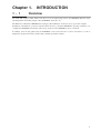
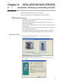
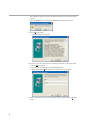
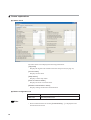
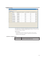
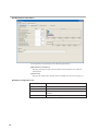
1
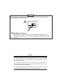
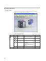
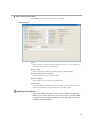
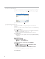
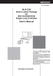
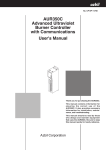
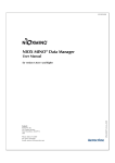
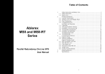
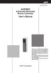
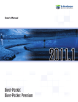
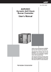
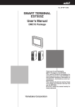
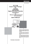
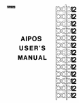
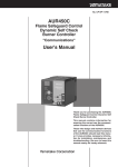
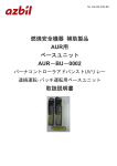
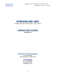
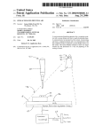
No. CP-SP-1187E
SLP-A45
Smart Loader Package
for the AUR450C
Dynamic Self-Checking
Burner Controller
User's Manual
DYNAMIC SELF CHECK
BURNER CONTROLLER
POWER
AUR450
EVENT
SHUTTER
FLAME
ALARM
DISP
RS-485
START
IG
ADDRESS
PV
MV
RST
LOADER
FLAME
VOLTAGE
Thank you for purchasing the SLP-A45
for AUR450C.
This manual contains information for
ensuring correct use of the SLP-A45. It
also provides necessary information for
installation, maintenance, and troubleshooting.
This manual should be read by those
who design and maintain equipment
that uses the AUR450C and SLP-A45.
Be sure to keep this manual nearby for
handy reference.
IMPORTANT
Do not apply a strong force while connecting a loader plug. Doing so
might damage the instrument.
Handling Precautions
Application of excessive force to the loader plug might cause
communication failure. If such failure happens, reconnect the plug
correctly.
NOTICE
Be sure that the user receives this manual before the product is used.
Copying or duplicating this user’s manual in part or in whole is forbidden. The information and specifications in this manual are subject to
change without notice.
Considerable effort has been made to ensure that this manual is free
from inaccuracies and omissions. If you should find an error or omission, please contact the azbil Group.
In no event is Azbil Corporation liable to anyone for any indirect, special
or consequential damages as a result of using this product.
© 2005-2012 Azbil Corporation All Rights Reserved.
The Role of This Manual
A total of five different manuals are available for the AUR450C. Read them as necessary for your specific requirements. If a manual you require is not available, contact the azbil Group or its dealer.
AUR450C Dynamic Self-Checking Burner Controller
Manual No. CP-SP-1196E
Personnel in charge of design, mounting, operation, and maintenance of
combustion equipment using the AUR450C should read this manual.
It describes the mounting, wiring, trial-run adjustment, maintenance, inspection of the AUR450C.
AUR450C Dynamic Self-Checking Burner Controller "Communications"
Manual No. CP-SP-1176E
Those using the communications funcrions of the AUR450C should read this
manual.
It is necessary for making the program of the device that uses AUR450C. An
operation status and various data of AUR450C can be read by using the
communication.
This manual describes a details of display, outline of CPL communications,
communications procedures, a list of communications data, how to remedy
trouble, and communications specifications.
SLP-A45 Smart Loader Package for the AUR450C Dynamic Self-Checking
Manual No. CP-SP-1187E
Burner Controller
This manual.
This manual is supplied with the SLP-A35/SLP-A45 Smart Loader Package.
The manual describes the software used to make various settings for
AUR450C using a personal computer. Personnel in charge of design or setting of a system using AUR450C must thoroughly read this manual.
The manual describes installation of the software into a personal computer,
operation of the personal computer, various functions, and setup procedures.
AUD300C1000 Advanced Ultraviolet Flame Detector
Manual No. CP-SP-1141E
The manual describes the mounting, wiring, maintenance and inspection,
and troubleshooting when the AUD300C1000 is built-into the combustion
equipment.
AUD300C2000 Advanced Ultraviolet Flame Detector
Manual No. CP-SP-1170E
The manual describes the mounting, wiring, maintenance and inspection,
and troubleshooting when the AUD300C2000 is built-into the combustion
equipment.
i
Organization of This User's Manual
This manual is organized as follows:
Chapter 1.
INTRODUCTION
Be sure to read this chapter before you start using the Smart Loader Package.
This chapter describes the required operating environment for the personal computer and briefly
introduces its features.
Chapter 2.
INSTALLATION AND BASIC OPERATION
This chapter describes how to install, start up and quit the SLP-A45, its functions, screen
configurations and basic operations.
Chapter 3.
SETUP
This chapter describes methods of operations relating to the setup such as the environment setup,
file operations, communications with the AUR450C and data setup.
Chapter 4.
CHECKING THE STATUS OF THE AUR450C
This chapter describes how to display the status of the AUR450C, including operating
conditions, alarm history, maintenance information, etc.
Chapter 5.
CHECKING COMBUSTION STATUS
This chapter describes how to display the playback data stored in the AUR450C and the trend
monitoring data relating to operating conditions.
Chapter 6.
TROUBLESHOOTING
This chapter describes error messages that are displayed when trouble occurs and how to remedy
trouble.
ii
Contents
The Role of This Manual
Organization of This User's Manual
Conventions Used in This Manual
Chapter 1.
INTRODUCTION
1-1 Overview • • • • • • • • • • • • • • • • • • • • • • • • • • • • • • • • • • • • • • • • • • • • • • • • • • • • • • • • • • • • • • • • • • • • 1
1-2 System Operating Environment • • • • • • • • • • • • • • • • • • • • • • • • • • • • • • • • • • • • • • • • • • • • • 2
■ Hardware • • • • • • • • • • • • • • • • • • • • • • • • • • • • • • • • • • • • • • • • • • • • • • • • • • • • • • • • • • • • • • • • 2
■ Hardware configuration • • • • • • • • • • • • • • • • • • • • • • • • • • • • • • • • • • • • • • • • • • • • • • • • • 2
Chapter 2.
INSTALLATION AND BASIC OPERATION
2-1 Installation, Starting up and Quitting the SLP • • • • • • • • • • • • • • • • • • • • • • • • • • • • • • • 3
■ Installation • • • • • • • • • • • • • • • • • • • • • • • • • • • • • • • • • • • • • • • • • • • • • • • • • • • • • • • • • • • • • • 3
■ Starting up the SLP • • • • • • • • • • • • • • • • • • • • • • • • • • • • • • • • • • • • • • • • • • • • • • • • • • • • • • 8
■ Quitting the SLP • • • • • • • • • • • • • • • • • • • • • • • • • • • • • • • • • • • • • • • • • • • • • • • • • • • • • • • • • 8
2-2 Description of Functions • • • • • • • • • • • • • • • • • • • • • • • • • • • • • • • • • • • • • • • • • • • • • • • • • • • 9
■ SLP functions • • • • • • • • • • • • • • • • • • • • • • • • • • • • • • • • • • • • • • • • • • • • • • • • • • • • • • • • • • • 9
■ Screen explanations • • • • • • • • • • • • • • • • • • • • • • • • • • • • • • • • • • • • • • • • • • • • • • • • • • • 10
Chapter 3.
SETUP
3-1 Setup screen and Menu configuration list • • • • • • • • • • • • • • • • • • • • • • • • • • • • • • • • • • 11
■ Overview • • • • • • • • • • • • • • • • • • • • • • • • • • • • • • • • • • • • • • • • • • • • • • • • • • • • • • • • • • • • • • • 11
■ Setup screen • • • • • • • • • • • • • • • • • • • • • • • • • • • • • • • • • • • • • • • • • • • • • • • • • • • • • • • • • • • 11
■ Menu configuration list • • • • • • • • • • • • • • • • • • • • • • • • • • • • • • • • • • • • • • • • • • • • • • • • • 11
3-2 Method of Setup • • • • • • • • • • • • • • • • • • • • • • • • • • • • • • • • • • • • • • • • • • • • • • • • • • • • • • • • • • • 12
Chapter 4.
CHECKING THE STATUS OF THE AUR450C
■ Overview • • • • • • • • • • • • • • • • • • • • • • • • • • • • • • • • • • • • • • • • • • • • • • • • • • • • • • • • • • • • • • • 15
■ Screen explanations • • • • • • • • • • • • • • • • • • • • • • • • • • • • • • • • • • • • • • • • • • • • • • • • • • • 16
Chapter 5.
CHECKING COMBUSTION STATUS
■ Overview • • • • • • • • • • • • • • • • • • • • • • • • • • • • • • • • • • • • • • • • • • • • • • • • • • • • • • • • • • • • • • • 19
■ Screen explanations • • • • • • • • • • • • • • • • • • • • • • • • • • • • • • • • • • • • • • • • • • • • • • • • • • • 20
iii
Chapter 6.
TROUBLESHOOTING
6-1 Error Messages • • • • • • • • • • • • • • • • • • • • • • • • • • • • • • • • • • • • • • • • • • • • • • • • • • • • • • • • • • • • 25
■ Communications error messages • • • • • • • • • • • • • • • • • • • • • • • • • • • • • • • • • • • • • • 25
■ File error messages • • • • • • • • • • • • • • • • • • • • • • • • • • • • • • • • • • • • • • • • • • • • • • • • • • • • 25
■ Startup error messages • • • • • • • • • • • • • • • • • • • • • • • • • • • • • • • • • • • • • • • • • • • • • • • • 26
■ Other error messages • • • • • • • • • • • • • • • • • • • • • • • • • • • • • • • • • • • • • • • • • • • • • • • • • • 26
6-2 Remedies for Communications Errors • • • • • • • • • • • • • • • • • • • • • • • • • • • • • • • • • • • • • 27
Conventions Used in This Manual
The following conventions are used in this manual:
Handling Precautions:
Handling Precautions indicate items that the user should pay attention to
when handling the SLP-A45.
Note:
:
Notes indicate information that might benefit the user.
This indicates the item or page that the user is requested to refer to.
(1), (2), (3):
Numbers within parentheses indicate steps in a sequence or parts of an
explanation.
[OK] button:
Indicates a selectable button on a personal computer screen.
[Menu]:
Indicates messages and menus displayed on the personal computer.
[Menu] → [Quit]:
Indicates the order to select the [Menu] first and then select the
[Quit] displayed on the personal computer.
>>:
Indicates the result of an operation, details displayed on the personal computer or other devices, or the state of the device after operation.
[Ctrl] key, [A] key:
Indicates keys on the keyboard.
[Ctrl]+[A] key:
Indicates the operation of pressing the [A] key on the keyboard while the
[Ctrl] key is pressed.
iv
Chapter 1.
1 - 1
INTRODUCTION
Overview
The SLP-A45 (simply called “SLP” from here on) is an engineering tool for the AUR450C Dynamic SelfChecking Burner Controller (simply called “AUR450C” from here on).
The SLP runs on Windows 2000/XP/Vista/7 (simply called "Windows" from here on) on a personal computer.
Installation of the SLP on a personal computer allows the user to check the AUR450C's operating conditions or to
configure the AUR450C from the PC. After setup, operation of the AUR450C is more convenient.
In addition, since the data gathered by the AUR450C can be read on the PC, it can be stored there as a file or
displayed in graph format using commercially available spreadsheet software.
1
1 - 2
System Operating Environment
The following system environment is required for using the SLP:
■ Hardware
Item
Description
Personal Computer Target model
Memory
PC/AT compatibles with a Pentium chip or higher
32M byte or more
Operating system Windows 2000/XP/Vista (32 bit)/7 (32 bit, 64 bit)
Peripheral Devices Display
SVGA 800 X 600 dot or more,
XGA 1024 X 768 dot or more
Serial port *
9-pin, serial port, 1 channel or more
Hard disk drive
Hard disk with at least 40M byte of free space
CD-ROM drive
1 drive or more
Pointing device
Windows-compatible mouse or equivalent device
* It is recommended to use a personal computer with 9-pin serial port built-in.
If your personal computer does not have any serial port, you may use any of
the extension adapters listed below to connect the loader cable.
However, note that the operation may become unstable depending on the
personal computer environment.
• Special interface (port replicator)
Adapter specially designed for each personal computer (special adapter for
each personal computer model)
• CF card adapter
CF232 manufactured by Elan Digital systems
URL: http://www.elandigitalsystems.com/interface/cf232.php
Operation confirmed personal computer, IBM's Thinkpad A31
REX-CF60 manufacture by RATOC.
URL: http://www.ratocsystems.com/products/subpage/cf60.html(Japanese)
• USB adapter
USB-RSAQ3 manufactured by I•O DATA DEVICE, INC.
URL: http://www.iodata.jp/prod/mobile/serial/2004/usb-rsaq3/(Japanese)
Operation confirmed personal computer, IBM's Thinkpad A31
When connecting the USB cable, check the port No.
The port No. may vary depending on the USB cable connection position.
■ Hardware configuration
AUR450C
DYNAMIC SELF CHECK
BURNER CONTROLLER
POWER
AUR450
EVENT
SHUTTER
FLAME
ALARM
DISP
RS-485
START
IG
ADDRESS
PV
MV
RST
LOADER
FLAME
VOLTAGE
Write
Communications
Special Cable
Read
2
Install
SLP
Chapter 2.
2 - 1
INSTALLATION AND BASIC OPERATION
Installation, Starting up and Quitting the SLP
■ Installation
Install the SLP on the hard disc of personal computer.
Use the system disk that you have purchased as the backup system.
This section describes how to install the SLP on a personal computer.
Handling Precautions
• This disk does not contain the operating system, and you cannot use
without the operating system.
• If you start up the Installer while another application is running, the
Installer may malfunction.
Remove other resident applications from their directories before starting
up the Installer.
The SLP sometimes cannot be started up depending on the combination of
other applications and drivers.
For details on Windows and personal computer settings, refer to the
User’s Manuals provided with Windows and the personal computer.
● Installing the SLP
(1) Set the CD-ROM in the CD-ROM drive of your personal computer.
>>The following screen appears:
(2) Click [Install SLP-A45 for AUR450C] button.
>>The installation program is then started up automatically and the following
screen appears:
3
If the SLP having the old version has been installed, the screen shown below
appears.
Click the [OK] button to uninstall the SLP-A45 having the old version.
(3) Click [Next >] button.
>>The following screen appears :
(4) If you agree to the software license agreement and wish to install the loader,
click the [Next >] button.
If you abort the installation, click the [Cancel] button.
>>When clicking the [Next >] button, the following screen appears :
(5) Enter a registered user name and company name, and then click the [Next >]
button.
4
>>The following screen appears :
(6) Click [Next >] button.
>>The following screen appears :
Note
• To change the installation destination directory, click [Browse...] button.
(7) Click [Next >] button.
>>The following screen appears :
5
Note
• Check on necessary files.
To display a PDF file, it is absolutely necessary to install Adobe Reader.
For details, refer to;
Note on next page.
(8) Check on (put a check mark :
) software components you wish to install and
click [Next >] button.
>>The following screen appears :
Note
• To change the program folder, enter the new folder name.
(9) Click [Next >] button.
>>The following screen appears :
(10)Click [Next >] button.
>>The following screen appears :
6
(11)Click [Finish >] button.
>>When the installation is completed successfully, the screen will return to
the Windows screen.
Note
• Installation of Adobe Reader
If the Adobe Reader is not installed in your personal computer, install it using
any of the following procedures:
• Download the Adobe Reader from Adobe Systems' home page.
• Install [adberdr60_enu_full.exe] from the CD-ROM.
7
■ Starting up the SLP
Double-click the SLP-A45(AUR450C)
icon on the desk top or click [Start]
button at the lower portion of the screen and select [Programs] → [SLP] →
[SLP-A45(AUR450C)].
>>The SLP is started up and the menu window is displayed.
Note
• For the operating system details and the mouse setup, refer to User’s
Manuals provided with Windows.
■ Quitting the SLP
Click
icon at the top right of the screen.
The operation is the same by selecting the [Menu] → [Quit].
8
2 - 2
Description of Functions
■ SLP functions
The figure below shows the various functions and what they do.
Menu
Set up
Various settings
Maintenance
Status check
Alarm history
• Sets up tag names, event settings
and RS-485 communications.
• Gives updated details on device
operating status, alarm history and
maintenance-related information.
Maintenance information
Monitor
Playback monitor
• Displays playback data stored in the
AUR450C and operation status trends.
Trend monitor
Port setup
• Port selection for the SLP cable.
Communication port
9
■ Screen explanations
● Menu screen
The picture below is basic SLP screen. When the SLP starts up and when
subscreens are exited, this menu screen appears.
• Menu configuration list
Menu
Icon
Menu
Help
10
Sub Menu
Description
Shortcut Keys
Setup
Displays the setup window.
[Ctrl]+[S]
Maintenance
Displays the maintenance window.
[Ctrl]+[J]
Monitor
Displays the monitor window.
[Ctrl]+[M]
Port setup
Changes the communication
environment.
For details how to setup, refer to;
●Step 1(setting up the port)
(page 12).
[Ctrl]+[E]
-
Quit
Quits the SLP.
[Ctrl]+[Q]
-
Version(A)
Displays the version information.
[Ctrl]+[A]
Chapter 3.
3 - 1
SETUP
Setup screen and Menu configuration list
■ Overview
The setup screen is used to configure settings and write them to the AUR450C so
that it functions according to the user's particular control requirements.
■ Setup screen
Setup item
Menu bar
Tool bar
Select window
Message window
■ Menu configuration list
Menu
Icon
File
Communications
Sub Menu
Description
Shortcut Keys
Open
Loads an existing settings data
file.
[Ctrl]+[O]
Save As
Saves the settings to a file with
a file name provided by the user.
[Ctrl]+[S]
Quit
Quits setup and returns to the
main menu screen.
[Ctrl]+[Q]
Read
Reads settings from the AUR450C.
(AUR450C to SLP)(R)
[Ctrl]+[R]
Write
Writes settings to the AUR450C.
(SLP to AUR450C)(W)
[Ctrl]+[W]
Initialize settings
(AUR450C)
[Ctrl]+[N]
Initializes the AUR450C using
the default settings.
11
3 - 2
Method of Setup
Set up in the following steps:
Step 1: Setting up the port
Step 2: Setting up the data
Step 3: Saving setup data
Step 4: Writing the setup data
Handling Precautions
• When writing from the SLP to the AUR450C, or reading from the
AUR450C to the SLP, be sure to perform step 1, setting up the port.
Otherwise, [Can't open the communication port] is displayed and
communications are not possible. After the environment setup has been
done once or after a file operation, further setup is not required.
● Step 1 (setting up the port)
(1) Click the [Port setup] on the menu screen.
The operation is the same by selecting the [Ctrl] + [E] keys.
>>The Port Setting dialog box appears.
(2) Set the communications port. Select the port to which the SLP cable is
connected.
(3) Click [OK] button.
12
● Step 2 (setting up the data)
Click [Setup] on the menu screen. Set the various data.
• Setup screen
[Tag]
If desired, enter a name for the device being used (etc.). Up to 33 characters, or
16 double-byte characters, can be entered.
[Event setup]
Select if each event condition is enabled ([Yes]) or disabled ([No]).
[RS-485 communications settings]
Set the data format and transmission speed.
[Various settings]
Input a light level for each color of FLAME LED.
[AUR memo]
Store information on maintenance, etc. as a memo. Up to 85 characters, or 42
double-byte characters, can be entered. Enter according to need.
Handling Precautions
• Set the red FLAME LED light level ≤ the green FLAME LED light level.
Failure to set correctly will result in the error message, [The red FLAME
LED light level is ≥ the green FLAME LED light level,] and it will not be
possible to save the settings.
13
● Step 3 (saving setup data)
When all setup is finished (basic setup, extended setup, and playback setup), save
the settings to a file. If the same parameters are desired again, setup will be easy.
(1) The operation is the same by selecting the [File] → [Save As] or [Ctrl]+[A]
keys.
>>The Save As dialog box appears.
(2) Enter the file name, and click [Save] button.
● Step 4 (writing the setup data)
Write settings from the SLP or settings called up from a saved file to the
AUR450C.
(1) Use the special cable to connect the personal computer to the AUR450C body.
(2) Turn the AUR450C ON.
(3) Click
icon. The operation is the same by selecting [Communications] →
[Write (SLP to AUR450C)] in the menu bar.
>>The message [Save the settings to the AUR450C?] is displayed.
(4) Click [OK] button.
>>This starts writing of the setup data. When writing ends, [Save cmpleted.]
is displayed.
(5) Click [OK] button.
Handling Precautions
• If writing is not possible, refer to;
Chapter 6. TROUBLESHOOTING.
To verify the saved settings, read them back from the AUR450C.
(1) Click
icon.
The operation is the same by selecting [Communications] → [Read
(AUR450C to SLP)] in the menu bar.
>>The message [Read settings from the AUR450C?] is displayed.
(2) Click [OK] button.
>>When reading ends, [Reading completed.] is displayed.
(3) Click [OK] button.
14
Chapter 4.
CHECKING THE STATUS
OF THE AUR450C
■ Overview
The status of the AUR450C, including operation status, alarm history and
maintenance information, can be checked. To do so, click [Maintenance] on the
main menu screen (page 10).
The maintenance screen is divided into two tabbed windows, as explained in detail
on the following pages:
• Status check
Displays information such as flame voltage and equipment information about
the AUR450C.
• Alarm history
Displays alarm history for the past 16 alarms.
• Maintenance information
Displays equipment information for the AUR450C.
Handling Precautions
• When writing data from the SLP to the AUR450C, or reading from the
AUR350C to the SLP, be sure that the communications port has been
set. Once the port has been set, no further setup is required unless the
environment changes. For details how to setup, refer to;
●Step 1 (setting up the port) (page 12)
● Menu configuration list
Menu
File
Options
Sub Menu
Description
Save all
Saves all information displayed
on the maintenance screen.
Quit
Quits the maintenance screen.
Command line
Displays a command line.
Shortcut Keys
[Ctrl]+[Q]
-
15
■ Screen explanations
● Status check
The status check screen displays the following information:
[Tag name]
Displays the tag that was entered on the basic setup screen (see page 13).
[Current status]
Displays current status.
[Setup status]
Displays current setup status.
[Event occurrence status]
Displays the event occurrence status.
[RS-485 communications status]
Displays settings for RS-485 communications.
● Button configuration list
Button
Clear event
Description
Clear the present event.
Note
• When communications are normal, [Communicating …] is displayed on the
bottom left of the screen.
16
● Alarm history
The alarm history screen displays alarm history for the past 16 alarms. The most
recent alarm history is displayed as [Alarm history 1]. When a 17th alarm occurs,
the oldest alarm history is deleted.
[Alarm history]
For each alarm occurrence, the alarm code, sequence code on lockout,
cumulative operation time, cumulative combustion time and cumulative
combustion count are displayed.
● Button configuration list
Button
Description
Initialize alarm history Initializes the designated alarm history.
17
● Maintenance information
The maintenance screen displays the following information:
[Maintenance information]
Displays cumulative alarm count and other times/counts that are useful for
maintenance.
[AUR memo]
Displays the AUR memo entered on the extended setup screen (see page 13).
● Button configuration list
Button/Check box
18
Description
Initialize alarm count
Allows each alarm count to be initialized.
Initialize time/count
Allows each event time/count to be initialized.
Alarm count zoom
Zooms in on the alarm count graph when the checkbox is
checked.
Time zoom
Zooms in on the time graph when the checkbox is checked.
Chapter 5.
CHECKING COMBUSTION
STATUS
■ Overview
Playback data stored in the AUR450C can be displayed, and the trend monitoring
data relating to operating conditions can be checked. To do so, click [Monitor] on
the main menu screen (page 10).
● Monitor screen
There are two monitoring screens, one for playback and one for trends. Details are
explained on the following pages:
• Playback monitor
This screen displays the four (max.) playback data items stored in the
AUR450C. The displayed playback data can be saved and later read back.
• Saving of playback data as a CSV file
• Reading of saved playback data
• Copying of playback screen to the Windows clipboard
• Trend monitor
This screen is for monitoring the running state of the AUR450C in the form of a
trend graph.
• Screen display of trends for max. of eight data items
• Saving of sampled data as CSV file
• Reading of CSV data
• Copying of trend screen to the Windows clipboard
• Data type
Flame voltage, Shutter cycle period, relay output,
User-defined data (any analog data that can be communicated)
• Sampling cycle
Variable within the range 1 to 3600s
• Max. sampling count
60,000
Note
• A "CSV file" is the data format that can be handled in third-party
spreadsheet software such as Microsoft Excel. In this format, sampled trend
data can be interpreted in spreadsheet software.
Handling Precautions
• Sampling cycle may change depending on the communications timing.
When measuring with exact timing, use a recorder or data logger.
19
■ Screen explanations
● Playback monitor
The playback monitor displays playback data for 8 seconds before the occurrence
of the latest lockout and for 2 seconds after the occurrence.
Flame voltage graph
Digital signals graph
COMM.
• Menu configuration list
Menu
Icon
Sub Menu
-
Read
Read the playback data.
-
Playback monitor
-
Open CSV
Reads and displays CSV data
saved in a file.
-
Save CSV... *
Outputs the playback data in CSV
data format.
-
Options
Quit the playback monitor
Shortcut Keys
File
Trend monitor
Quit
Description
[Ctrl]+[Q]
-
Copy flame voltage Copies a flame voltage graph to
graph to Clipboard the Windows clipboard.
-
-
Copy digital signals Outputs a digital signals graph to
graph to clipboard the Windows clipboard.
-
-
Command Line
Changes the display to the trend
monitor.
-
Displays the command Line
window.
-
*: The CSV data output function saves playback monitor data that has been read
from the AUR450C to a file. After CSV data has been read once and modified
it cannot be saved to another CSV file.
Note
• When communications are normal, [COMM.] is displayed on the bottom left of
the screen.
20
● How to operate the playback monitor
• Reading playback data
The playback monitor displays playback data for 8 seconds before the occurrence
of the latest lockout and for 2 seconds after the occurrence. Therefore, be sure to
wait 2 seconds after lockout before reading the data. If the data is read within 2
seconds, it might not be correctly displayed. If this happens, click [Read] again. In
this case, the playback display background color will be blue.
Handling Precautions
• When the device is not used (AUR450 power is OFF) for 4 hours or
more, the playback data is deleted.
When the AUR450C and the loader are correctly connected, the operations
described below are also available.
• Saving playback data
The data sampled using the playback monitor can be saved into a file in the CSV
format. The sampled data saved in CSV format can be processed using spreadsheet
applications, such as Microsoft Excel.
Handling Precautions
• Before quitting the SLP, save the playback data. If not saved, the
data will disappear.
• Reading of saved playback data
Playback data saved in CSV format can be displayed on the playback monitor
screen. In this case, the screen background is orange.
• Use of the command line
Data can be read or written or the mode switched by directly entering
communications commands on the command line.
Handling Precautions
• Transmission of the wrong command may result in trouble on the
AUR450C. For this reason, take sufficient care when describing
command types, addresses, data and other information.
• For details on communications commands and data addresses, refer
to;
AUR450C "Communications" User's Manual CP-SP-1176E.
21
● Trend monitor
By means of the connection to the AUR450C, operational trends are always
drawn in real time.
Flame voltage graph
Digital signals graph
• Menu configuration list
Menu
Icon
-
File
Shortcut Keys
Quit the trend monitor
[Ctrl]+[Q]
Trend monitor
Start/Stop
Starts/stops the trend monitor
[Ctrl]+[T]
CSV Read
Reads CSV data that has been
saved to a file.
-
Save CSV... *
Outputs the trend data in CSV
format.
[Ctrl]+[X]
-
Copy flame voltage
graph to &clipboard
Copies a flame voltage graph to
the Windows clipboard.
-
-
Copy digital signals
graph to clipboard
Outputs a digital signals graph to
the Windows clipboard.
-
Changes the display to the
playback monitor.
-
-
Options
Description
Quit
Trend monitor
Playback monitor
Sub Menu
-
-
Setup Trend monitor Displays the Setup window.
User function For details, refer to; next page.
-
Command Line
window.
-
Displays the Command Line.
*: The CSV data output function saves playback monitor data that has been read
from the AUR450C to a file. After CSV data has been read once and modified
it cannot be saved to another CSV file.
22
• Icon list
Icon
Description
Returns the graph to the start time.
Returns the graph by 1/2 screen.
Returns the graph by 1/4 screen.
Advances the graph by 1/4 screen.
Advances the graph by 1/2 screen.
Advances the graph to the latest time.
Specify a time scale of the graph.
1min.
2min.
10min.
1hr.
12hrs.
24hrs.
Auto
● How to operate the trend monitor screen
• Setup
From the monitoring screen, select [Options] → [Setup] to modify the settings
shown below. Cycle, display high limit, and display low limit apply to all trends.
• Trend monitor
Setting Item
Description
Setting Range
Factory Setting
Cycle
Setting of sampling cycle
Display low limit
of left axis
Lower value of vertical axis of -1999 to display upper limit
screen display
1 to 3600s
-1
1
Display high limit
of left axis
Upper value of vertical axis of Display lower limit to 9999
screen display
6
Display low limit
of right axis
Lower value of vertical axis of -1999 to display upper limit
screen display
-1
Display high limit
of right axis
Upper value of vertical axis of Display lower limit to 9999
screen display
6
• User function
Setting Item
Axis
Description
Specify an axis used for the graph.
Setting Range
0 : Left
1 : Right
User-defined Address of relevant data when the data type Address of
address
is set as "user type"
communicable data
Decimal point Number of digits to be displayed after the
decimal point
0 to 3
Note
• For User-defined address, refer to;
AUR450C "Communications" User's Manual CP-SP-1176E.
Handling Precautions
• When the user-defined address is specified, make the decimal point
setting.
23
• Starting the data sampling
When the setup is completed, start up the trend monitor.
Click
icon.
The same operation can be started by selecting [Trend Monitor] → [Trend
Monitor Start].
The data sampling is started, and then the trend of the specified parameters is
displayed on the screen.
• Once the trend monitor is started, it continues until the stop operation is
performed or the data for 60,000 cycles is sampled.
• If the trend monitor is not stopped, it will continue until data has been sampled
60,000 times.
• The screen can be change to the "Numeric Monitor" screen while the trend
monitor is running. However, the loader cannot be exited and the screen cannot
be change to the "Setup" screen without first quitting the trend monitor.
• Stopping the data sampling
Select [Trend Monitor] → [Trend Monitor Stop].
The trend monitor is then stopped.
• Saving sampled data
The data sampled using the trend monitor can be saved into a file in the CSV
format. The sampled data saved in the CSV format can be processed using
spreadsheet applications, such as Microsoft Excel.
Handling Precautions
• The data can be saved into a file even while the trend monitor is
running.
• Before quitting the SLP, save the playback data. If not saved, the data
will disappear.
• Reading the data sampling
Trend monitor data that has been saved can be displayed on the trend monitor
screen. In this case, the screen background is indigo blue.
• Saving copy flame voltage graph and copy digital signals graph to clipboard
The information displayed on the trend monitor screen can be saved as is by
copying it to the Windows clipboard.
24
Chapter 6.
6 - 1
TROUBLESHOOTING
Error Messages
■ Communications error messages
Category
Message
Description
Communications Can't open the communications port. Other software that uses the
error
communications port has tried to
use the port at the same time.
Remedy
Do not use, at the same time, other
software that uses the
communications port.
Wrong communications port number. Refer to;
section 6-2,"Remedies for
Communication Errors" (page 27)
AUR450C
status error
A communications error occurred. A system error occurred.
Abort: End the program.
Retry: Try again to connect.
After checking section 6-2,
"Remedies for Communication
Errors" (page 27), either quit or
restart the loader.
A communications error occurred.
The program has ended.
After checking section 6-2,
"Remedies for Communication
Errors" (page 27), restart the loader.
A communications error occurred.
To resume, read/write/clear again.
After checking section 6-2,
"Remedies for Communication
Errors" (page 27), try the loader
operation again.
Can't support the connected
SLP-A45
The loader currently in use is not
compatible with the AUR450C.
Contact the azbil Group or its dealer.
Connected instruments may not
be supported by this loader.
Check the listing.
Wrong communications port number. Refer to;
SLP jack is not fully connected.
section 6-2,"Remedies for
No power supply of AUR450C.
Communication Errors" (page 27)
■ File error messages
Category
File name
error
Disk error
File error
Message
Description
Remedy
This filename is not valid.
An invalid file name has been
entered.
Enter the correct file name.
This file cannot be found.
Make sure that the correct path
and filename are given.
A non-existent file name has
been entered.
Correctly enter the name of an
existent file.
This filename is a reserved
device name.
Use a different filename.
A file name reserved as a device
name has been entered.
Enter the correct file name.
Not enough free space on disk.
There is not enough free space on
disk.
Secure enough free space on disk.
The device is not ready.
The disk is not prepared.
Prepare a disk, and repeat the
operation.
Cannot make file.
The save destination is a CD-ROM.
Save to a different destination.
File name too long.
The file name is too long.
Limit file names to 255 or less
characters.
Not a configuration file.
The indicated file is not a valid
configuration file.
Select a valid configuration file.
25
■ Startup error messages
Category
Loader system
error
Message
Can't start up two or more
SLP-A45s at once.
Description
An attempt was made to start up
three or more SLP-A45s at once.
Remedy
Click [OK] button.
■ Other error messages
Message
The red FLAME LED light level is >= the
green FLAME LED light level.
26
Description
The value set for the red FLAME
LED light level was not less than
or equal to the value of the green
FLAME LED light level.
Remedy
Set the red FLAME LED light level
≤ green FLAME LED light level.
6 - 2
Remedies for Communications Errors
● When [Can’t open the communications port] is displayed.
From the Windows control panel, use the device manager to check the current
COM port setting.
[Control Panel] → [System] → [Hardware] → [Device Manager]
If a USB cable is used, the COM port may differ according to the USB connector
location.
● When [A communications error occurred] is displayed.
Check the SLP cable. The SLP may not be fully connected. Make sure that power
is being supplied to the devices.
● When [Connected instruments may not be supported by this loader. Check the listing] is
displayed.
Change the connecting instruments to the AUR450C.
Check the SLP cable. The SLP may not be fully connected. Make sure that power
is being supplied to the devices.
27
Revision History
Printed
date
Manual Number
Edition
Revised pages
Description
Aug. 2005 CP-SP-1187E 1st Edition
May 2008
Apr. 2009
Sep. 2009
Apr. 2012
2nd Edition 10
3rd Edition
Endpaper
End of a book
4th Edition i
5th Edition
1, 2, 27
3
21
Back cover
Menu screen changed.
Manual name changed.
RESTRICTIONS ON USE deleted.
Terms and Conditions added.
Manual name changed.
Descriptions were changed because of change of
the company name from Yamatake to Azbil.
Descriptions were changed due to compatibility
with Windows 7.
The [SLP-A45/SLP-35 install] screen was changed.
Handling precaution of Reading playback data
was added.
Terms and Conditions was changed.
Terms and Conditions
We would like to express our appreciation for your purchase and use of Azbil Corporation's products.
You are required to acknowledge and agree upon the following terms and conditions for your purchase of Azbil Corporation's
products (field instruments, control valves, and control products), unless otherwise stated in any separate document,
including, without limitation, estimation sheets, written agreements, catalogs, specifications and instruction manuals.
1. Warranty period and warranty scope
1.1 Warranty period
Azbil Corporation's products shall be warranted for one (1) year from the date of your purchase of the said
products or the delivery of the said products to a place designated by you.
1.2 Warranty scope
In the event that Azbil Corporation's products has any failure attributable to azbil during the aforementioned warranty
period, azbil shall, without charge, deliver a replacement for the said product to the place where you purchased, or
repair the said product and deliver it to the aforementioned place.
Notwithstanding the foregoing, any failure falling under one of the following shall not be covered under this warranty:
(1) Failure caused by your improper use of Azbil Corporation's products
(noncompliance with conditions, environment of use, precautions, etc. set forth in catalogs, specifications,
instruction manuals, etc.);
(2) Failure caused for other reasons than Azbil Corporation's products;
(3) Failure caused by any modification or repair made by any person other than azbil or azbil's
subcontractors;
(4) Failure caused by your use of Azbil Corporation's products in a manner not conforming to the intended
usage of that product;
(5) Failure that the state-of-the-art at the time of Azbil Corporation's shipment did not allow us to predict; or
(6) Failure that arose from any reason not attributable to Azbil Corporation, including, without limitation, acts
of God, disasters, and actions taken by a third party.
Please note that the term "warranty" as used herein refers to equipment-only-warranty, and Azbil Corporation
shall not be liable for any damages, including direct, indirect, special, incidental or consequential damages in
connection with or arising out of Azbil Corporation's products.
2. Ascertainment of suitability
You are required to ascertain the suitability of Azbil Corporation's products in case of your use of the same with
your machinery, equipment, etc. (hereinafter referred to as "Equipment") on your own responsibility, taking the
following matters into consideration:
(1) Regulations and standards or laws that your Equipment is to comply with.
(2) Examples of application described in any documents provided by Azbil Corporation are for your reference
purpose only, and you are required to check the functions and safety of your Equipment prior to your use.
(3) Measures to be taken to secure the required level of the reliability and safety of your Equipment in your use
Although Azbil Corporation is constantly making efforts to improve the quality and reliability of Azbil
Corporation's products, there exists a possibility that parts and machinery may break down.
You are required to provide your Equipment with fool-proof design, fail-safe design, anti-flame
propagation design, safety design, or the like so that the said Equipment may satisfy the level of the
reliability and safety required in your use, whereby preventing any occurrence of physical injuries, fires,
significant damage, and so forth.
3. Precautions and restrictions on application
Azbil Corporation's products other than those explicitly specified as applicable (e.g. azbil Limit Switch For Nuclear
Energy) shall not be used in a nuclear energy controlled area (radiation controlled area).
Any Azbil Corporation's products shall not be used for/with medical equipment.
In addition,
you are required to conduct a consultation with our sales representative and understand detail specifications,
cautions for operation, and so forth by reference to catalogs, specifications, instruction manual , etc. in case that
you intend to use Azbil Corporation's products for any purposes specified in (1) through (6) below.
Moreover, you are required to provide your Equipment with fool-proof design, fail-safe design, anti-flame
propagation design and other designs of protection/safety circuit on your own responsibility to ensure the
reliability and safety, whereby preventing problems caused by failure or nonconformity.
(1) For use under such conditions or in such environments as not stated in technical documents, including
catalogs, specification, and instruction manuals
(2) For use of specific purposes, such as:
* Nuclear energy/radiation related facilities
[For use outside nuclear energy controlled areas] [For use of Azbil Corporation's Limit Switch For
Nuclear Energy]
* Machinery or equipment for space/sea bottom
* Transportation equipment
[Railway, aircraft, vessels, vehicle equipment, etc.]
* Antidisaster/crime-prevention equipment
* Burning appliances
* Electrothermal equipment
* Amusement facilities
(3) Supply systems such as electricity/gas/water supply systems, large-scale communication systems, and
traffic/air traffic control systems requiring high reliability
(4) Facilities that are to comply with regulations of governmental/public agencies or specific industries
(5) Machinery or equipment that may affect human lives, human bodies or properties
(6) Other machinery or equipment equivalent to those set forth in items (1) to (5) above which require high
reliability and safety
4. Precautions against long-term use
Use of Azbil Corporation's products, including switches, which contain electronic components, over a prolonged
period may degrade insulation or increase contact-resistance and may result in heat generation or any other
similar problem causing such product or switch to develop safety hazards such as smoking, ignition, and
electrification.
Although acceleration of the above situation varies depending on the conditions or environment of use of the
products, you are required not to use any Azbil Corporation's products for a period exceeding ten (10) years
unless otherwise stated in specifications or instruction manuals.
5. Recommendation for renewal
Mechanical components, such as relays and switches, used for Azbil Corporation's products will reach the end of
their life due to wear by repetitious open/close operations.
In addition, electronic components such as electrolytic capacitors will reach the end of their life due to aged
deterioration based on the conditions or environment in which such electronic components are used.
Although acceleration of the above situation varies depending on the conditions or environment of use, the
number of open/close operations of relays, etc.
as prescribed in specifications or instruction manuals, or depending on the design margin of your machine or
equipment, you are required to renew any Azbil Corporation's products every 5 to 10 years unless otherwise
specified in specifications or instruction manuals.
Field instruments (sensors such as pressure/flow/level sensors, regulating valves, etc.) will reach the end of their
life due to aged deterioration of parts.
For those parts that will reach the end of their life due to aged deterioration, recommended replacement cycles are
prescribed. You are required to replace parts based on such recommended replacement cycles.
6. Other precautions
Prior to your use of Azbil Corporation's products, you are required to understand and comply with specifications
(e.g., conditions and environment of use), precautions, warnings/cautions/notices as set forth in the technical
documents prepared for individual Azbil Corporation's products, such as catalogs, specifications, and instruction
manuals to ensure the quality, reliability, and safety of those products.
7. Changes to specifications
Please note that the descriptions contained in any documents provided by Azbil Corporation are subject to change
without notice for improvement or for any other reason.
For inquires or information on specifications as you may need to check, please contact our branch offices or sales
offices, or your local sales agents.
8. Discontinuance of the supply of products/parts
Please note that the production of any Azbil Corporation's products may be discontinued without notice.
For repairable products, we will, in principle, undertake repairs for five (5) years after the discontinuance of those
products. In some cases, however, we cannot undertake such repairs for reasons, such as the absence of repair
parts.
For field instruments, we may not be able to undertake parts replacement for similar reasons.
Specifications are subject to change without notice.
(09)
1-12-2 Kawana, Fujisawa
Kanagawa 251-8522 Japan
URL: http://www.azbil.com
1st edition: Aug. 2005 (W)
5th edition: Apr. 2012 (M)