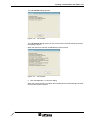
1
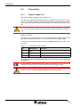
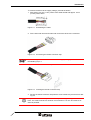
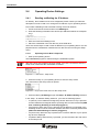
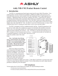
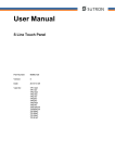
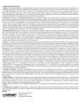
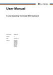
User manual
Quick start TSwin .net
Part Number:
80860.653
Version:
1
Date:
25.07.2005
Valid for:
TSwin .net 4.00
BT03Ax
BT05Ax
BT07Ax
BT21Ax
TP11Ax
TP21Ax
Version
1
Date
25.07.2005
Modifications
First Edition
This manual, including all illustrations contained herein, is copyright protected. Use of this manual by any third
party in departure from the copyright provision is forbidden. No part of this manual may be reproduced, translated or electronically or photographically archived or altered without the express written consent from Sütron
electronic GmbH. Violations shall be cause for damage liability.
Sütron electronic reserves the right to make any changes that contribute to technical improvement.
Overall Table of Contents
1
Important Notes ....................................................................................................... 1-1
1.1
2
1.1.1
General Symbols ................................................................................. 1-1
1.1.2
Specific Symbols ................................................................................. 1-1
1.2
Safety Notes ............................................................................................. 1-2
1.3
Intended Use............................................................................................. 1-2
1.4
Target Group............................................................................................. 1-2
Introduction .............................................................................................................. 2-1
2.1
Hardware Requirements ...................................................................... 2-1
2.1.2
Software Requirements ....................................................................... 2-1
2.2
Aim of this Quick Start ............................................................................. 2-1
2.3
Connecting................................................................................................ 2-2
2.4
2.4.1
Supply Voltage 24 V ............................................................................ 2-2
Operating Device Settings ........................................................................ 2-4
Reading out/Setting the IP Address..................................................... 2-4
2.4.1.1
Operating Device With a Keyboard ............................................................................2-4
2.4.1.2
Operating Device With a Touch Screen .....................................................................2-5
2.4.2
Display Mode Settings (TP11, TP21 only) ........................................... 2-5
Installation................................................................................................................ 2-7
3.1
4
Requirements............................................................................................ 2-1
2.1.1
2.3.1
3
Symbols .................................................................................................... 1-1
Installing TSwin .net.................................................................................. 2-7
Creating a visualization with TSwin .net .................................................................. 2-8
4.1
Creating the Visualization ......................................................................... 2-8
4.2
Adding a Communications Protocol.......................................................... 2-9
4.2.1
Adding the protocol .............................................................................. 2-9
4.2.2
Inserting the Protocol into the Project ................................................ 2-10
4.3
Compiling the Project and Creating the Required Files .......................... 2-11
4.4
Transferring the Project .......................................................................... 2-12
5
Summary ............................................................................................................... 2-14
6
We are interested in your opinion! ......................................................................... 2-15
A
Index ........................................................................................................................ 3-1
i
Overall Table of Contents
ii
Important Notes
1
Important Notes
1.1
Symbols
The symbols in this manual are used to draw your attention on notes and dangers.
1.1.1
General Symbols
Danger
This symbol is used to refer to instructions which, if ignored or not carefully followed
could result in personal injury.
Note
This symbol indicates application tips or supplementary notes.
Reference to source of information
This symbol refers to detailed sources of information on the current topic.
1.1.2
Specific Symbols
The following symbols indicate specific dangers which could result in damage to
equipment or personal injury or even up to the death of the operator.
Danger - Electric Shock
Danger - Corrosive
Danger - Toxic
Danger - Explosive
Danger - Fire
Danger - Infrared Light
Danger - Electrostatic Charge
1-1
Important Notes
1.2
Safety Notes
–
Read this manual carefully before using the operating device. Keep this manual
in a place where it is always accessible to all users.
–
Proper transportation, handling and storage, placement and installation of this
product are prerequisites for its subsequent flawless and safe operation.
–
This user manual contains the most important information for the safe operation
of the device.
–
The user manual, in particular the safety notes, must be observed by all personnel working with the device.
–
Observe the accident prevention rules and regulations that apply to the operating
site.
–
Installation and operation must only be carried out by qualified and trained personnel.
1.3
Intended Use
–
The device is designed for use in the industry.
–
The device is state-of-the art and has been built to the latest standard safety requirements. However, dangerous situations or damage to the machine itself or
other property can arise from the use of this device.
–
The device fulfills the requirements of the EMC directives and harmonized European standards. Any modifications to the system can influence the EMC behavior.
1.4
Target Group
All configuration and programming work in connection with the automation system
must be performed by trained personnel only (e.g. qualified electricians, electrical engineers).
The configuration and programming personnel must be familiar with the safety concepts of automation technology.
1-2
Introduction
2
Introduction
2.1
Requirements
2.1.1
Hardware Requirements
–
Operating device BTxxAx or TP11Ax
–
24VDC voltage supply (SELV)
–
Network or Intranet access
–
PC to carry out the programming process (recommended hardware: Intel
Pentium IV processor with 2.0 GHz or equivalent, 512 MB RAM, approx. 200 MB
free disk space, CD-ROM drive, mouse, USB port)
–
Optional mouse, keyboard, USB stick for the operating device
2.1.2
–
Software Requirements
Operating system Windows 2000 or
–
Operating system Windows XP home/professional
–
TSwin .net version 4.00
2.2
Aim of this Quick Start
This quick start provides you with a simple introduction to working with the TSwin .net
programming software and guides you through a simple, fully functional project.
This quick start describes only how to create a visualization under Windows XP since
the process is identical under Windows 2000.
For information on questions you may have that fall outside the scope of this quick
start, please refer to the detailed TSwin .net documentation (available from
www.suetron.de or on the TSwin .net-CD).
The examples below show you how to
–
create a new project for your operating device with the aid of a template
–
add a communications protocol to the project
–
translate (compile) the project and
–
transfer the created terminal file to the operating device.
Knowledge of how to operate PCs and experience with Microsoft Windows operating
systems is required.
2-1
Introduction
2.3
Connecting
2.3.1
Supply Voltage 24 V
The supply voltage is supplied via connector X1.A.
The device can optionally be equipped with an additional connector (X1.B). In this
case, X1.A is looped through to X1.B and can be used to provide voltage supply to
other components (e.g. bus node). The pin assignment is the same for both connectors.
The maximum continuous power allowed to flow from connector X1.A to X1.B is 5 A.
To avoid an overload, an external fuse protection must be installed (e.g. fusible cutout).
The device is protected against polarity reversal. The device will not operate if the
polarity is incorrect.
This device is in Protection Class I. To ensure safe operation, a safety extra-low voltage (SELV) according to DIN EN 61131 must be used as the supply voltage.
Connector in the operating terminal: Phoenix COMBICON MSTBV 2,5/3-GF 3-pin
connector
Table 2-1
Pin
Pin assignment supply voltage
Designation
1
Function
Low-Noise Ground
2
0V
Supply Voltage 0 V
3
24 VDC
Supply Voltage 24 VDC
The appropriate Phoenix COMBICON MSTB 2,5/3-STF female connector is supplied
as standard.
A cable with finely stranded wires with a minimum cross-section of 0.75 mm² and a
maximum cross-section of 2.5 mm² must be used for the supply voltage.
Hazardous voltages can exist inside electrical systems that can pose a danger to
humans. There is a risk of electric shock when touching live parts!
2-2
Introduction
To connect the device to the supply voltage, proceed as follows:
1. Strip approx. 30 mm (1.181") off the outer cable sheath and approx. 5 mm
(0.197") off the wires.
Figure 2-1
Assembling the cable
2. Fit the wires with wire end ferrules and connect the wires to the connector.
Figure 2-2
Connecting the female connector strip
If you are using a shielded cable to connect to the supply voltage, you should connect
the shielding to pin 1.
3. Insert the female connector strip in male connector X1.A.
Figure 2-3
Inserting the female connector strip
4. Secure the female connector strip with the screw interlock to prevent it from sliding out.
A separate cable must always be used for the protective grounding at the threaded
bolts. The cable must have a minimum cross-section of 1.5 mm² and must be as
short as possible.
2-3
Introduction
2.4
Operating Device Settings
2.4.1
Reading out/Setting the IP Address
On delivery, the IP address is set to be assigned by DHCP. Below you will find a
description on how to read out or change the IP address of your operationg device.
First create a IPSetting.ini file to be able to assign a fixed IP address:
1. Create a text document and rename it to IPSetting.ini.
2. Write the following information into this file (the addresses below are examples
only):
[IPConfig]
IPAddress=192.168.100.100
SubnetMask=255.255.255.0
3. Save and close the IPSetting.ini file.
4. Place the created file in the root directory of the USB stick.
There are several ways to read out the IP address of your operating device: it is displayed when the visualization is started and can also be read out using the Setup
menu.
2.4.1.1
Operating Device With a Keyboard
1. Start up the operating device.
The Launch.exe program is started during the initialization phase.
After the Launch.exe program has been started, you have 2 seconds to enter the
setup mode; otherweise the visualization is started.
Figure 2-4
Launch.exe - setup main
2. Press the F1 key on your operating device to enter the setup mode.
The main menu of the setup mode is opened.
Figure 2-5
Keys of the main menu for the setup mode
3. Press the F3 key (IP Setting) to open the Setup - IP Address Setting submenu.
In the Setup - IP Address Setting submenu, you have the following options:
2-4
–
F1 (DHCP): The IP address is assigned by DHCP. When the F1 key is pressed,
a new IP address is asssigned and the operating device must be rebooted (USB
stick containing IPSetting.ini must be plugged in).
–
F2 (Fixed IP): When the F2 key is pressed, the IP address you specified in the
IPSetting.ini file is used as a fixed IP address and DHCP is thereby deactivated
(USB stick with IPSetting.ini must be plugged in).
–
F3 (Current IP): When this key is pressed, the current IP address of your operating device is displayed.
–
F4 (Back to Main): When this key is pressed, you are returned to the main menu
of the setup mode.
Introduction
To start the visualization, reboot the operating device.
2.4.1.2
Operating Device With a Touch Screen
1. Start up the operating device.
The Launch.exe program is started during the initialization phase.
After the Launch.exe program has been started, you have 2 seconds to enter the
setup mode; otherweise the visualization is started.
Figure 2-6
Launch.exe - setup main
2. Press the Press For Setup Main Menu button on your operating device to enter
the setup mode.
The main menu of the setup mode is opened.
Figure 2-7
Main menu of setup mode - touch screen
3. Press the IP Setting button to open the Setup - IP Address Setting submenu.
In the Setup - IP Address Setting submenu, you have the following options:
–
Fixed IP: When this button is pressed, the IP address you specified in the
IPSetting.ini file is used as a fixed IP address and DHCP is thereby deactivated
(USB stick with IPSetting.ini must be plugged in).
–
Current IP: When this button is pressed, the current IP address of your operating
device is displayed.
–
DHCP: The IP address is assigned by DHCP. When the F1 button is pressed, a
new IP address is asssigned and the operating device must be rebooted (USB
stick containing IPSetting.ini must be plugged in).
–
Back to Main: When pressed, you are returned to the main menu of the setup
mode.
To start the visualization, reboot the operating device.
2.4.2
Display Mode Settings (TP11, TP21 only)
When using the operating devices TP11 and TP21, you can choose between four
different orientations when displaying screen contents.
1. Start up the operating device.
The Launch.exe program is started during the initialization phase.
After the program has been started, you have 2 seconds to enter the setup mode;
otherwise the visualization is started.
2-5
Introduction
Figure 2-8
Launch.exe - setup main
2. Press the Press For Setup Main Menu button on your operating device to enter
the setup mode
The main menu of the setup mode is opened.
Figure 2-9
Main menu of setup mode - touch screen
3. Press the Touch Registry button to open the Touch Registry submenu.
4. Press the Change Display Mode button to open the submenu which contains
the display mode (display orientation) settings.
The dialog with the display mode settings appears.
Figure 2-10
Display mode
In this dialog, you can choose the display orientation best suited for the mounting
position of your operating device:
Table 2-2
Display mode
Dialog option
A
Portrait_Left
A
Landscape
Portrait_Right
A
Landscape_Upside_Down
A
5. After choosing your display settings, press the OK button to close the dialog.
6. A message is displayed to inform you that the new display settings become
effective once the operating device is rebooted.
7. Confirm this message with OK.
8. Reboot the operating device.
The operating device is now booted with the display settings you selected.
2-6
Installation
3
Installation
3.1
Installing TSwin .net
TSwin .net is a visualization software which allows you to create a visualization for
Sütron operating devices.
TSwin .net is based on Microsoft’s .NET technology. If the .NET framework is not already installed on your programming PC, it will be installed during installation of
TSwin.net.
1. Insert the TSwin .net CD.
2. Choose a setup language.
3. Click the TSwin.net programming icon.
4. Follow the instructions of the installation program to install TSwin .net .
2-7
Creating a visualization with TSwin .net
4
Creating a visualization with TSwin .net
This chapter describes an example of how to create a simple project using a
template, to add a communications protocol and to transfer the project to the
operating device. For this example we use a TP11AM device with a PROFIBUS
connection.
4.1
Creating the Visualization
1. Start TSwin .net.
2. Select New / Project folder from the File menu.
The Create project folder (templates) dialog appears.
Figure 4-1
Create project folder (templates)
3. Expand the TP1x folder.
4. Select the template TP11AM.
5. Click the Next > button.
The Create project folder (place to store) dialog appears.
Figure 4-2
2-8
Create project folder (place to store)
Creating a visualization with TSwin .net
6. Click the ... button, to select the location where you want to store your project.
7. Assign a name to your project.
8. Click the Finish button.
The project is created in TSwin .net and a project tree is created.
4.2
Adding a Communications Protocol
4.2.1
Adding the protocol
1. In the project tree (window Project Folder), click Communication with the right
mouse button.
A selection menu appears.
Figure 4-3
Selection menu Communication
2. Click the item New controller.
The Protocol selection dialog appears.
Figure 4-4
Protocol selection
3. Select the communications protocol Profibus DP.
4. Click OK.
2-9
Creating a visualization with TSwin .net
The Create controller (Controller create) dialog appears.
Figure 4-5
Create controller
5. Leave the name unchanged and click OK.
You have just added a communications protocol for the controller and now need to
insert it into your project.
4.2.2
Inserting the Protocol into the Project
1. In your project tree, expand Project management.
The components in your project are displayed.
Figure 4-6
Expaned project tree
2. In the project tree, click the entry Profibus DP with your left mouse button and
keep the button pressed.
3. While keeping the mouse button pressed, drag the Profibus DP entry onto the
entry First project.
4. Release the left mouse button.
2-10
Creating a visualization with TSwin .net
The Profibus DP entry is inserted into your project.
Figure 4-7
Expanded project tree after insertion
You have now added the communications protocol for the controller and inserted it
into your project.
4.3
Compiling the Project and Creating the
Required Files
To be able to transfer the project to the operating device, you first need to compile it,
thereby creating the required terminal file.
1. In the project tree, click First project with the right mouse button.
A selection menu is opened.
Figure 4-8
Selection menu First Project
2. Click the Create option.
2-11
Creating a visualization with TSwin .net
The project is compiled and the terminal file is created in the same directory as your
project.
If errors or warnings occur, they are displayed in the output window.
4.4
Transferring the Project
The project can be transferred in different ways. You can:
–
Transfer the project to the FTP server of the operating device via Ethernet or
–
Store the project on a USB stick and copy it manually into the internal memory of
the operating device
This quick start only contains a description of how to transfer the project to the FTP
server. For this process, you need to know the IP address of your operating device
(see chapter Operating Device Settings).
1. Select Transmit / Download / Transfer from the Extras menu.
The Create INI file... dialog appears.
Figure 4-9
Create INI file and transfer files
2. Enter the IP address of your operating device into the IP address field.
3. Click the Start button.
2-12
Creating a visualization with TSwin .net
The FTP transfer dialog appears.
Figure 4-10
FTP transfer
The FTP transfer dialog shows you the current status of the file transfer process to
the operating device.
When the transfer is finished, the OK button becomes active.
Figure 4-11
FTP transfer
4. Click the OK button, to close the dialog.
When the project transfer is complete, the operating device is automatically rebooted
and the new project is started.
2-13
Summary
5
Summary
In the course of this quick start you have
2-14
–
installed the software necessary to work with the operating device,
–
started up the operating device,
–
created a project in TSwin .net using a default template,
–
added a communications protocol,
–
transferred the project to the operating device.
We are interested in your opinion!
6
We are interested in your opinion!
We would like to hear your suggestions, requests and criticisms in relation to this
quick start.
We will examine any and all suggestions and comments and, if possible, incorporate
them into the documentation.
Send us your comments and suggestions for improvement to the following address:
Sütron electronic GmbH
Dokumentation
Kurze Str. 29
70794 Filderstadt
GERMANY
Tel: +49 - (0) 711 - 77098-0
Fax: +49 - (0) 711 - 77098-60
E-mail: [email protected]
2-15
We are interested in your opinion!
2-16
A Index
C
communication.................................................. 2-9
communications protocol ... 2-8, 2-9, 2-10, 2-11
connecting......................................................... 2-2
I
Intended use ..................................................... 1-2
L
Launch.exe ..................................... 2-4, 2-5, 2-6
N
network ............................................................. 2-1
O
operating device with a keyboard ..................... 2-4
P
PROFIBUS......................... 2-8, 2-9, 2-10, 2-11
R
recommended hardware ................................... 2-1
S
Safety notes ...................................................... 1-2
supply voltage 24 V........................................... 2-2
Symbols
General ..................................................... 1-1
Specific ..................................................... 1-1
T
Target Group..................................................... 1-2
template ........................................ 2-1, 2-8, 2-14
Touch-Bediengerät ........................................... 2-5
TSwin .net ............................ 2-1, 2-7, 2-8, 2-14
U
USB stick ................................................. 2-4, 2-5
USB-Stick................................................. 2-1, 2-4
V
visualization ........................... 2-4, 2-5, 2-7, 2-8
W
Windows 2000 .................................................. 2-1
Windows XP...................................................... 2-1
3-1
3-2
Sütron electronic GmbH
Kurze Straße 29
70794 Filderstadt
Tel.:
0711 / 77098-0
Fax.:
0711 / 77098-60
E-Mail: [email protected]
Internet: www.suetron.de