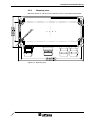
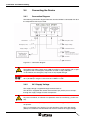
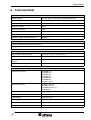
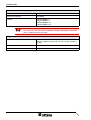
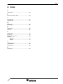
1
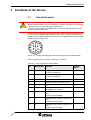
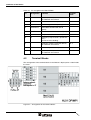
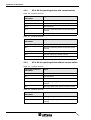
User Manual
HMI Linkbox HL01 DP/MPI
Part Number:
80860.603
Version:
1
Date:
07.05.2005
Valid for:
HL01 DP/MPI
Version
1
Date
07.05.2005
Modifications
First edition
This manual, including all illustrations contained herein, is copyright protected. Use of this manual by any third
party in departure from the copyright provision is forbidden. No part of this manual may be reproduced, translated or electronically or photographically archived or altered without the express written consent from Sütron
electronic GmbH. Violations shall be cause for damage liability.
Sütron electronic reserves the right to make any changes that contribute to technical improvement.
Overall Table of Contents
Overall Table of Contents
1
Important Notes ....................................................................................................... 1-1
1.1
Symbols .................................................................................................... 1-1
1.1.1
General Symbols ................................................................................. 1-1
1.1.2
Specific Symbols ................................................................................. 1-1
1.2
Safety Notes ............................................................................................. 1-2
1.3
Intended Use............................................................................................. 1-2
1.4
Target Group............................................................................................. 1-2
2
Introduction .............................................................................................................. 2-3
3
Installation and Commissioning ............................................................................... 3-1
3.1
Unpacking the Device ............................................................................... 3-1
3.2
Identification.............................................................................................. 3-1
3.3
Mounting the Device ................................................................................. 3-2
3.3.1
Front View............................................................................................ 3-2
3.3.2
Mounting view ...................................................................................... 3-3
3.4
4
3.4.1
Connection Diagram ............................................................................ 3-4
3.4.2
24 V Supply Voltage ............................................................................ 3-4
Interfaces of the Device ........................................................................................... 4-1
4.1
Round Connector...................................................................................... 4-1
4.2
Terminal Blocks ........................................................................................ 4-2
4.2.1
X1 to X4 ............................................................................................... 4-3
4.2.2
X5 to X6 for operating device with consent switch .............................. 4-4
4.2.3
X5 to X6 for operating device without consent switch ......................... 4-4
4.3
4.3.1
5
Connecting the Device.............................................................................. 3-4
PROFIBUS DP / MPI ................................................................................ 4-5
Termination .......................................................................................... 4-5
Maintenance and Servicing ..................................................................................... 5-1
5.1
General ..................................................................................................... 5-1
6
Technical Data......................................................................................................... 6-1
A
Index ......................................................................................................................... I-1
1
Overall Table of Contents
2
Important Notes
1
Important Notes
1.1
Symbols
The symbols in this manual are used to draw your attention on notes and dangers.
1.1.1
General Symbols
Danger
This symbol is used to refer to instructions which, if ignored or not carefully followed
could result in personal injury.
Note
This symbol indicates application tips or supplementary notes.
Reference to source of information
This symbol refers to detailed sources of information on the current topic.
1.1.2
Specific Symbols
The following symbols indicate specific dangers which could result in damage to
equipment or personal injury or even up to the death of the operator.
Danger - Electric Shock
Danger - Corrosive
Danger - Toxic
Danger - Explosive
Danger - Fire
Danger - Infrared Light
Danger - Electrostatic Charge
1-1
Important Notes
1.2
Safety Notes
–
Read this manual carefully before using the operating device. Keep this manual
in a place where it is always accessible to all users.
–
Proper transportation, handling and storage, placement and installation of this
product are prerequisites for its subsequent flawless and safe operation.
–
This user manual contains the most important information for the safe operation
of the device.
–
The user manual, in particular the safety notes, must be observed by all personnel working with the device.
–
Observe the accident prevention rules and regulations that apply to the operating
site.
–
Installation and operation must only be carried out by qualified and trained personnel.
1.3
Intended Use
–
The device is designed for use in the industry.
–
The device is state-of-the art and has been built to the latest standard safety requirements. However, dangerous situations or damage to the machine itself or
other property can arise from the use of this device.
–
The device fulfills the requirements of the EMC directives and harmonized European standards. Any modifications to the system can influence the EMC behavior.
1.4
Target Group
All configuration, programming, installation, commissioning, operating and maintenance work in connection with the automation system must be performed by trained
personnel only (e.g. qualified electricians, electrical engineers, etc.).
The configuration and programming personnel must be familiar with the safety concepts of automation technology.
The operating personnel must have been trained in handling the controller and be
familiar with the operating instructions.
The installation, commissioning and maintenance personnel must have an education
which entitles them to work on automation systems.
1-2
Introduction
2
Introduction
The HMI linkbox HL01 DP/MPI is designed for use in particular when you have to
connect or disconnect hand-held operating devices during operation to an active
PROFIBUS-DP or MPI bus. The HMI linkbox HL01 DP/MPI prevents any disruption
to an existing emergency stop circuit and to bus communication.
The connection is set up using an internal repeater with direction reversal.
Terminating resistors fitted on the device enable it to terminate the bus. You can
switch on these terminating resistors with DIP switches inside the HL01 DP/MPI, if
required.
The hand-held operating device is connected using a 19-pin circular connector with
a bayonet lock. The maximum length of the cable connecting the hand-held operating device is 10 meters (32.808 ft) with a baud rate of 12 MBit/s.
2-3
Introduction
2-4
Installation and Commissioning
3
Installation and Commissioning
3.1
Unpacking the Device
Unpack all parts carefully and check the contents for any visible damage in transit.
Also check whether the shipment matches the specifications on your delivery note.
If you notice damages in transit or discrepancies, please contact our sales department immediately.
3.2
Identification
The device can be identified by means of the nameplate.
Figure 3-1
Nameplate (example)
1
Order number
2
Firmware revision level (when device is initially supplied)
3
Voltage and current specification
4
Serial number
3-1
Installation and Commissioning
3.3
Mounting the Device
To ensure the required degree of protection, you must check that all empty PG
glands are filled with sealing plugs and all PG glands containing cables are screwed
tight. You must also ensure that all of the screws used to secure the cover have been
tightened evenly.
If you wish to ensure the required degree of protection, do not use screws with a
countersunk head to mount the device!
3-2
3.3.1
Front View
Figure 3-2
Front view with PG glands
1
Gland M16 x 1.5 (emergency stop and outgoing supply voltage)
2
Gland M16 x 1.5 (emergency stop and incoming supply voltage)
3
Gland M16 x 1.5 (with blind plug for optional connection of command devices)
4
Device connector
5
Retaining device for dust cap of device connector
6
Screwed cable gland M16 x 1.5 (PROFIBUS-DP IN)
7
Screwed cable gland M16 x 1.5 (PROFIBUS-DP OUT)
Installation and Commissioning
3.3.2
Mounting view
Mount the device on a level surface, while the cover is unscrewed and removed.
Figure 3-3
Mounting view
3-3
Installation and Commissioning
3.4
Connecting the Device
3.4.1
Connection Diagram
The following connection diagram illustrates how the linkbox is connected with all of
the components that may be used.
Figure 3-4
Connection diagram
RISK OF SERIOUS INJURY OR DEATH!
The linkbox with order number 81214.300 must NOT be used together with an operating device with an emergency stop button and with a stop pushbutton!
In this linkbox, the emergency stop circuit is only looped through!
The connecting cable for the TesiMod hand-held operating device must NOT exceed
10 m (32.808 ft) in length if a baud rate of 12 MBit/s is used!
3.4.2
24 V Supply Voltage
The supply voltage is supplied through terminal block X1.
The device is equipped with another terminal block (X2) which you use to loopthrough the supply voltage to further components.
The maximum continuous current allowed to flow from terminal block X1 to X2 is 2 A.
To prevent overload, an external fuse protection must be installed (e.g. fusible cutout).
The device has reverse polarity protection. In case of wrong polarity, the device will
not operate.
This is a protection class I device. For safe operation, safety extra-low voltage
(SELV) in accordance with DIN EN 61131 must be used for the supply voltage.
3-4
Installation and Commissioning
Connector in the operating device: 3 pin Phoenix COMBICON MSTBV 2,5/3-GF connector
Table 3-1
Pin
Pin assignment - supply voltage
Designation
1
Function
Low-Noise Ground
2
0V
Supply Voltage 0 V
3
24 VDC
Supply Voltage 24 VDC
A suitable female connector strip of the type Phoenix COMBICON MSTB 2,5/3-STF
is supplied.
A cable with finely stranded conductors with a minimum cross-section of 0.75 mm²
and a maximum cross-section of 2.5 mm² must be used for the voltage supply.
Hazardous voltages can exist inside electrical installations that can pose a danger to
humans. Coming in contact with live parts may result in electric shock!
Do the following to connect the device to the supply voltage:
1. Strip approx. 30 mm (1.181") off the outer sheath of the cable and approx. 5 mm
(0.197") off the wires.
Figure 3-5
Preparing the cable
2. Attach wire end ferrules to the wires.
3. Insert the cable through the gland into the device.
4. Connect the wires to the terminal block.
If shielded connecting cables are used in the supply voltage area, the shield should
be connected to pin 1.
5. Secure the cable in place with a screwed cable gland land to prevent it from slipping out.
A separate conductor must always be provided for the protective grounding at the
terminal block. The conductor must have a minimum cross-section of 1.5 mm² and
must be kept as short as possible.
3-5
Installation and Commissioning
3-6
Interfaces of the Device
4
Interfaces of the Device
4.1
Round Connector
RISK OF SERIOUS INJURY OR DEATH!
Sütron electronic GmbH assumes no liability if customers undertake to assemble the
male connector of the operating device themselves!
If the pins are not properly assembled, this may result in failure of the bus system
and/or emergency stop circuit!
A 19-pin circular connector with a bayonet lock is used to connect an operating device. To prevent a break in the emergency stop circuit, the male connector of the
hand-held operating device being connected must be equipped with leading contacts
for the emergency stop circuit!
Figure 4-1
Looking onto pluggable side of female connector on HL01 DP/MPI
The pin assignment for the 19-pin connector is as follows:
Table 4-1
Pin assignment for HL01 DP/MPI
Pin
Designation
Function
1
0 V HT
Supply voltage for operating device
24 V/2 A at maximum
2
24 V HT
Supply voltage for operating device
24 V/2 A at maximum
3
Jumper in device connector to pin 4
4
Jumper in device connector to pin 3
5
Jumper in device connector to pin 15
6
Optionally used by command devices
24 V/500 mA at maximum
7
Ö
Emergency stop channel 2 (break contact)
Contact must be leading!
8
Ö
Emergency stop channel 2 (break contact)
Contact must be leading!
9
Ö
Emergency stop channel 1 (break contact)
Contact must be leading!
Terminal
Block
X5.1
4-1
Interfaces of the Device
Table 4-1
Pin
Pin assignment for HL01 DP/MPI
Designation
10
Function
Terminal
Block
Optionally used by command devices
24 V/500 mA at maximum
X6.5
11
CNTR
Direction reversal for repeater
12
PE
Low-noise ground for operating device
13
RxD/TxD-N
PROFIBUS DP/MPI RxD/TxD-N
(green)
14
RxD/TxD-P
PROFIBUS DP/MPI RxD/TxD-P (red)
15
16
Jumper in device connector to pin 5
Ö
Emergency stop channel 1 (break contact)
Contact must be leading!
17
18
19
4.2
Optionally used by command devices
24 V/500 mA at maximum
DGND
X6.4
Reference potential for repeater
Optionally used by command devices
24 V/500 mA at maximum
X5.2
Terminal Blocks
The arrangement of the terminal blocks in the linkbox is displayed on a label inside
the cover.
Figure 4-2
4-2
Arrangement of the terminal blocks
Interfaces of the Device
4.2.1
Table 4-2
X1 to X4
Terminal block X1
Connection terminal in
HMI linkbox
Signal
X1.1
Low-noise ground
X1.2
Supply voltage 0 V DC
X1.3
Supply voltage 0 V DC
X1.4
Supply voltage +24 V DC
X1.5
Supply voltage +24 V DC
X1.6
Emergency stop channel 1 (break contact)
X1.7
Emergency stop channel 2 (break contact)
Table 4-3
Terminal block X2
Connection terminal in
HMI linkbox
Signal
X2.1
Emergency stop channel 2 (break contact)
X2.2
Emergency stop channel 1 (break contact)
X2.3
Supply voltage +24 V DC
X2.4
Supply voltage +24 V DC
X2.5
Supply voltage 0 V DC
X2.6
Supply voltage 0 V DC
X2.7
Low-noise ground
Table 4-4
Terminal block X3
Connection terminal in
HMI linkbox
Signal
X3.1
PROFIBUS/MPI RxD/TxD-P red (incoming)
X3.2
PROFIBUS/MPI RxD/TxD-N green (outgoing)
Table 4-5
Terminal block X4
Connection terminal in
HMI linkbox
Signal
X4.1
PROFIBUS/MPI RxD/TxD-P red (outgoing)
X4.2
PROFIBUS/MPI RxD/TxD-N green (outgoing)
4-3
Interfaces of the Device
4.2.2
Table 4-6
Terminal block X5
Connection terminal in
HMI linkbox
Signal
X5.1
Consent switch left 1 (make contact)
X5.2
Consent switch right 2 (make contact)
X5.3
Not connected
X5.4
Message "Operating device connected" (make
contact)
X5.5
Message "Stop button pressed" (make contact)
Table 4-7
Terminal block X6
Connection terminal in
HMI linkbox
Signal
X6.1
Message "Stop button pressed" (make contact)
X6.2
Message "Operating device connected" (make
contact)
X6.3
Not connected
X6.4
Consent switch left 2 (make contact)
X6.5
Consent switch right 1 (make contact)
4.2.3
Table 4-8
X5 to X6 for operating device without consent switch
Terminal block X5
Connection terminal in
HMI linkbox
Signal
X5.1
Not connected
X5.2
Not connected
X5.3
Not connected
X5.4
Message "Operating device connected" (make
contact)
X5.5
Message "Stop button pressed" (make contact)
Table 4-9
4-4
X5 to X6 for operating device with consent switch
Terminal block X6
Connection terminal in
HMI linkbox
Signal
X6.1
Message "Stop button pressed" (make contact)
X6.2
Message "Operating device connected" (make
contact)
Interfaces of the Device
Table 4-9
Terminal block X6
Connection terminal in
HMI linkbox
Signal
X6.3
Not connected
X6.4
Not connected
X6.5
Not connected
4.3
PROFIBUS DP / MPI
The bus is looped though in the linkbox and also connected to the operating device
by means of a repeater with direction reversal.
The operating device is connected to the repeater as a segment.
The connecting cable for the TesiMod hand-held operating device must NOT exceed
10 m (32.808 ft) in length if a baud rate of 12 MBit/s is used!
4.3.1
Termination
The bus line is terminated in the linkbox.
With a point-to-point connection, you must always activate the termination. With a
multi-point connection, you only need to activate the termination at the cable end.
With a spurline, you must always deactivate the termination.
Termination of the segment cable must always be activated in the linkbox and in the
operating device.
The switch positions for ON or OFF are printed onto the termination switch. Only the
specified switch positions are allowed.
Table 4-10
S1
Termination switch
S2
S3
Bus
S4
Function
HT
I
I
I
I
Bus termination is switched ON
–
–
I
I
Bus termination is switched OFF
Legend for table:
I = Switch ON
- = Switch OFF
4-5
Interfaces of the Device
4-6
Maintenance and Servicing
5
Maintenance and Servicing
5.1
General
The HMI Linkbox is maintenance-free.
You should use a damp cloth to remove any dirt from the device.
5-1
Maintenance and Servicing
5-2
Technical Data
6
Technical Data
Electrical Data
Supply Voltage
24 V DC (SELV in Accordance with DIN EN 61131)
Residual Ripple
20 % Maximum
Minimum Voltage
19.2 V
Maximum Voltage
28.8 V
Power Consumption
0.2 A
Connected Load
5W
Fuse
Semiconductor Fuse, Self-resetting
Protection Against Polarity Reversal
Integrated
Connection System
Circular Connector with Bayonet Lock 19 Pin
Spring-Cage Connectors FFKDS/V1-5,08
Environmental Conditions
Temperature During Operation
- 25 °C to + 70 °C (- 13 °F to 158 °F)
Temperature During Storage, Transport
- 25 °C to + 70 °C (- 16 °F to 158 °F)
Relative Air Humidity for Operation and
Storage
10% to 95%, Non-Condensing
Application Area
Degree of Pollution 1, Overvoltage Category II
Standards and Guidelines
Interference Immunity
EN 61000-4-2
EN 61000-4-3
EN 61000-4-4
EN 61000-4-5
EN 61000-4-6
EN 61000-6-2
EN 61131 Part 2
Emitted Interference
EN 55011 Class A
EN 55022 Class A
EN 61000-6-3 Tab. A1
EN 61000-6-4
Equipment Requirements
EN 61131
Storage and Transportation
EN 61131 Part 2
Power Supply
EN 61131 Part 2
Electromagnetic Compatibility
89/336/EWG (Including all Applicable Amendments)
Degree of Protection
EN 60529
Impact Load, Shocks
EN 60068 Part 2-27
6-1
Technical Data
Standards and Guidelines (Cont.)
Sinusoidal Vibrations
EN 60068 Part 2-6
Corrosion Protection
EN 60950
Climate
DIN EN 60068-2-1
DIN EN 60068-2-2
DIN EN 60068-2-14
DIN EN 60068-2-30
This is a class A device. This device may cause radio interference in residential areas. In this case, the user may be required to introduce appropriate countermeasures, and to bear the cost of same.
Enclosure and Front Panel
Enclosure
Polycarbonate
80 mm x 160 mm x 85 mm (H x W x D) - (3.150" x 6.299" x
3.346")
Degree of Protection
IP65
Total Weight
Approx. 650 g
6-2
Index
A Index
C
Connecting........................................................ 3-4
F
Firmware revision level ..................................... 3-1
I
Identification...................................................... 3-1
Intended use ..................................................... 1-2
M
Maintenance ..................................................... 5-1
Mounting ........................................................... 3-2
N
Nameplate......................................................... 3-1
Normen ............................................................. 6-1
S
Safety notes ...................................................... 1-2
Servicing ........................................................... 5-1
Supply voltage 24 V .......................................... 3-4
Symbols
General ..................................................... 1-1
Specific ..................................................... 1-1
T
Target group ..................................................... 1-2
Technical data................................................... 6-1
Termination ....................................................... 4-5
U
Unpacking ......................................................... 3-1
I-1
Index
I-2
Sütron electronic GmbH
Kurze Straße 29
D-70794 Filderstadt
Phone: 0049 711 / 77098-0
Fax:
0049 711 / 77098-60
E-mail: [email protected]
Internet: www.suetron.com