1
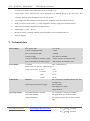
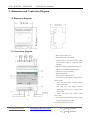
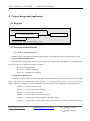
Guangzhou Video-star Electronics Industrial Co., Ltd R K-BUS○ KNX/DALI Gateway User manual-Ver. 1 BTDG-01/00.1 KNX/EIB Intelligent Installation Systems www.video-star.com.cn [email protected] Tel.: (8620)39338986 Fax: (8620)39338465 R GVS K-BUS○ KNX/EIB KNX/DALI Gateway Contents 1. General ................................................................................................................................................................. 3 1.1 DALI System Introduction .................................................................................................................................... 3 1.2 Product and functional overview .......................................................................................................................... 3 2. Technical data....................................................................................................................................................... 4 3. Dimension and Connection Diagram ................................................................................................................... 6 4. 3.1 Dimension diagram ............................................................................................................................................... 6 3.2 Connection diagram .............................................................................................................................................. 6 Project design and application ............................................................................................................................. 7 4.1 Diagram ................................................................................................................................................................ 7 4.2 Overview of the functions ..................................................................................................................................... 7 4.2.1 Control of the DALI devices ............................................................................................................................. 7 4.2.2 Group control of DALI devices ........................................................................................................................ 8 4.2.3 Scene control .................................................................................................................................................... 8 4.2.4 Broadcast control .............................................................................................................................................. 9 4.2.5 Staircase lighting (Dynamic operation mode) ................................................................................................... 9 4.2.6 Fault monitoring ............................................................................................................................................. 10 4.2.7 Behaviour on EIB or DALI voltage recovery ................................................................................................. 10 4.2.8 LED Display ................................................................................................................................................... 10 4.2.9 Manual operation / test function ..................................................................................................................... 12 4.3 5. Operating Steps ................................................................................................................................................... 13 Parameter setting description in the ETS .......................................................................................................... 13 5.1 Parameter window “General” ............................................................................................................................. 13 5.2 Parameter window “Channel A” ............................................................................................................................... 15 5.2.1 “Normal”operation mode ................................................................................................................................ 16 5.2.2 “Dynamic” operation mode............................................................................................................................. 21 5.3 Parameter window “Dynamic” ........................................................................................................................... 22 5.4 Parameter window "Control" ..................................................................................................................................... 24 5.5 Parameter window “Status” ....................................................................................................................................... 27 6. Description of communication objects ............................................................................................................... 31 6.1 Communication objects for individual DALI device .......................................................................................... 31 6.2 Communication objects for every DALI device ................................................................................................. 32 6.3 Communication objects for Group control .......................................................................................................... 35 6.4 Communication object for Scene control ............................................................................................................ 36 6.5 Communication objects for the entire channel .................................................................................................... 38 2 www.video-star.com.cn [email protected] Tel.: (8620)39338986 Fax: (8620)39338465 R GVS K-BUS○ KNX/EIB KNX/DALI Gateway 1. General The KNX/DALI gateway is designed for an intelligent building control system,which is used to connect KNX bus with DALI bus. As an interface device, it can convert the telegrams from KNX bus into the information that DALI devices can recognize, which includes DALI device address and control command, and send the information to DALI network and control DALI devices, e.g. switching, dimming , scene etc.. And the gateway can also detect fault of DALI device, and feed back the fault information to KNX bus. The KNX/DALI gateway can connect up to 64 DALI devices. Each DALI device can be switched, dimmed or set brightness value via a communication object. The DALI address assignment of 64 devices is implemented automatically or manually by the DALI Gateway, meanwhile, a DALI software tool is provided, which is used to modify the DALI devices address and test DALI devices etc. This manual provides detailed technical information about the DALI-Gateway for users as well as assembly and programming details, and explains how to use the gateway by the application examples. 1.1 DALI System Introduction There are up to 64 slave units in the same DALI network, and each salve units has a Short address. A salve unit can be assigned to up to 16 different groups at the same time. And host can send the information to all slave units. The main features of DALI protocol: asynchronous serial communication, 1200 baud, two-wire differential signal, a DALI interface can connect 64 salves, each salve can be addressed individually, but can’t perform two-way communication simultaneously. 1.2 Product and functional overview The KNX/DALI gateway is a modular installation device for fast installation in the distribution board on 35 mm mounting rails to DIN EN 60 715. The electrical connection is implemented using screw terminals. The connection to the bus is implemented using the supplied bus connection terminal. The input need be connected to an extra voltage supply. It is able to use the Engineering Tool Software ETS (ETS3 or later) with a VD4 file to allocate the physical address and set the parameters. The following functions can be set via the application program: Switching, dimming and set brightness value for each DALI device Scene control: can configure up to 16 different scenes for each DALI device. And there are two data types 3 www.video-star.com.cn [email protected] Tel.: (8620)39338986 Fax: (8620)39338465 R GVS K-BUS○ KNX/EIB KNX/DALI Gateway to recall and store the scenes of the DALI device: 1 bit and 1 byte Group control: Every DALI devices can be belonged to 16 different groups at the same time. And switching, dimming and set brightness value for each group Can configure the min. brightness value and the max. brightness value for each DALI device Send or response various status, e.g. switch, brightness, auxiliary supply and communication etc. Fault detection of lamps and ballasts for DALI devices LED display, e.g. error , run, init Broadcast control: switching, dimming and set brightness value for all DALI devices Staircase lighting 2. Technical data Power supply DALI Output Bus voltage, EIB 21~30V DC Current consumption, EIB < 12mA Power consumption, EIB < 360mW Auxiliary supply 100~240V AC,50/60Hz Current consumption, Auxiliary supply <28mA, at 220 V AC and max. load Power consumption, Auxiliary supply <6W, at 220 V AC and max. load 1 Channel Max. 64 DALI devices Distance between gateway and DALI device: Cable cross-section 0.5mm2 116m 2 0.75 mm 174 m 1 mm2 232 m 2 1.5 mm Connections EIB/KNX DALI output and Auxiliary supply 300 m Bus connection terminal(red/black),0.8 mm Ø, single-core Screw terminal Wire Range 0.5-2.5mm2 Torque 0.5N-m Operating/ display Programming button/ red LED For assignment of the physical address Green LED flashing The application layer works normally Yellow LED(Error) For displaying DALI devices fault, constant light 4 www.video-star.com.cn [email protected] Tel.: (8620)39338986 Fax: (8620)39338465 R GVS K-BUS○ KNX/EIB KNX/DALI Gateway Red LED(Init) For assignment DALI addresses, constant light For updating data of DALI Gateway, flashing light For initializing mode or detect DALI devices fault, fast flashing light For displaying the Auxiliary supply and operation are normal A short operation (<2s),for on/off all DALI devices to test some unconnected DALI devices; A long operation (2-5s),for updating DALI Gateway data A long operation (>5s),for assignment DALI addresses from 0 to 63 Green LED(Run) Test/Set button Housing Temperature range IP 20, EN 60 529 Operation -5℃……+45℃ Storage -25℃……+55℃ Transport -25℃……+70℃ Ambient conditions Max. air humidity <93%,except dewing Design Modular installation device (MDRC) Housing/colour Plastic housing, grey Installation On 35mm DIN-Rail, to EN 60 715 Dimension 90 mm ×72mm ×64mm Weight 0.3KG Application program Max. number of communication objects Max. number of group addresses Max. number of associations DALI Gateway, 1fold 235 250 250 5 www.video-star.com.cn [email protected] Tel.: (8620)39338986 Fax: (8620)39338465 R GVS K-BUS○ KNX/EIB KNX/DALI Gateway 3. Dimension and Connection Diagram 3.1 Dimension diagram 3.2 Connection diagram ①DALI Output negative pole ②DALI Output positive pole DALI ③Test/Set button, to test DALI devices, update DALI Gateway data or assignment DALI addresses. ④Red LED indicates programming the physical address, Green LED flashing indicates the application layer works normally. ⑤Programming button ⑥auxiliary power supply terminals ⑦ Red LED (Init) ON indicates assigning DALI address from 0; Red LED (Init) flashing indicates updating DALI Gateway data; Red LED (Init) fast flashing indicates initializing DALI devices or detect DALI devices fault. ⑧ Yellow LED (Error) ON indicates DALI devices fault. ⑨ Green LED (Run) ON indicates the Auxiliary supply and operation are normal. ⑩ EIB Bus terminal connection 6 www.video-star.com.cn [email protected] Tel.: (8620)39338986 Fax: (8620)39338465 R GVS K-BUS○ KNX/EIB KNX/DALI Gateway 4. Project design and application 4.1 Diagram AC230V K DALI-ballast KNX/DALI Gateway N D X A AC230V (power supply for DALI Gateway only) L I 4.2 Overview of the functions 4.2.1 Control of the DALI devices In DALI Gateway application, for control and monitoring of the DALI devices have the following two ways: Control of individual DALI device Each of the individual 64 DALI devices can be switched on/off, dimmed or the brightness can be adjusted with just one “Device Ax” communication object. As follow: Device Ax — Switch/Status Device Ax — Relative Dimming Device Ax — Brightness value/Status Control of every DALI device In addition, the DALI Gateway features an address-related individual option to control or read every single device. First of all, the communication object “Channel x — Selected Device” selects a device via its device address. Then the selected device can be individually controlled or read via the following communication objects. Channel x — Selected Device On/Off Channel x — Selected Device Rel. Dimming Channel x — Selected Device Set Value Channel x — Selected Device Status (switch status) Channel x — Selected Device Read Brightness (brightness status) Channel x — Selected Device Lamp Failure (lamp fault status, First of all, the communication object 7 www.video-star.com.cn [email protected] Tel.: (8620)39338986 Fax: (8620)39338465 R GVS K-BUS○ KNX/EIB KNX/DALI Gateway “Detect Ballasts” detects the DALI device via a telegram “1”, then the gateway will query its fault status and send or read the fault status.) Channel x — Selected Device Ballast Failure (ballast fault status, First of all, the communication object “Detect Ballasts” detects the DALI device via a telegram “1”, then the gateway will query its fault status and send or read the fault status.) Channel x — Selected Device Remove From Group Channel x — Selected Device Add to Group Channel x — Selected Device Query Own Group For example, we want to control the device A4. First of all, the communication object “Channel x — Selected Device” selects the device via its device address “5”. Then it can be directly controlled or monitored with the related communication objects, such as switch, dimming, monitored its status etc.. In any case, just one device can be selected. No device is selected after a download or EIB bus voltage recovery. The selected device stays selected after auxiliary supply or DALI bus voltage failure and recovery, as well as after reallocate DALI addresses. If DALI addresses are reallocated, the selected device may have been changed. 4.2.2 Group control of DALI devices DALI Gateway provides 16 groups. Every DALI devices can be belonged to 16 different groups at the same time. Thus more than one DALI devices can be controlled together via a communication object. First of all, put the controlled devices into a group when set parameters, then the communication object “Channel x — Selected Group” selects a group via its group number. And then the selected group can be individually controlled via the following communication objects. Channel x — Selected Group On/Off Channel x — Selected Group Rel. Dimming Channel x — Selected Group Set Value No group is selected after a download or EIB bus voltage recovery. The selected group stays selected after auxiliary supply or DALI bus voltage failure and recovery, as well as after reallocate DALI addresses. If DALI addresses are reallocated, the devices of the group may have been changed. The brightness of devices in the group are limited by their min. and max. brightness value. 4.2.3 Scene control DALI Gateway provides 16 scenes and different brightness value can be preset for each scene. Usually, up to 64 scenes can be used in the KNX system, but only the first 16 can be used for the DALI Gateway. So only use the first 16 scenes when KNX devices control DALI devices via the scene function. When a KNX device sends a scene 8 www.video-star.com.cn [email protected] Tel.: (8620)39338986 Fax: (8620)39338465 R GVS K-BUS○ KNX/EIB KNX/DALI Gateway telegram to DALI Gateway, the DALI devices which belong to the scene will be switched on with parameterized brightness. The current brightness value can be also stored in a scene. Switching a scene is not transition time, so the brightness value of the scene is directly transferred. Recall /store scene with 1-bit telegram or 8-bit telegram. 4.2.4 Broadcast control In the broadcast control mode, all the DALI devices in the channel can be switched on/off, dimmed or the brightness together with just one communication object. As follow: Channel x — On/Off Channel x — Relative Dimming Channel x — Set Brightness value If the brightness values of DALI devices are non-uniform, the transition time of brightness are also non-uniform. The brightness of devices are limited by their min. and max. brightness value. 4.2.5 Staircase lighting (Dynamic operation mode) A staircase lighting function with a cut-out warning time can be parameterized in the dynamic operating mode of DALI Gateway. For example, the staircase lighting function of a device is composed of two scenes ( see follow figure ),the start scene is 9, its run time is 5min and its brightness value is 100%. The end scene is 10, its run time is 2min and its brightness value is 40%. When the staircase lighting function is triggered via a telegram value “1”, the start scene 9 is run and brightness to 100%. After the operating time (5min) of the start scene has elapsed, the end scene 10 commences with brightness 40% and its operation time (2min). The device is switched off after the operation time of the end scene. The cut-out warning is implemented with the end scene. Process diagram is as follows: Note: Switching a scene is not transition time, so the brightness is changed quickly. 9 www.video-star.com.cn [email protected] Tel.: (8620)39338986 Fax: (8620)39338465 R GVS K-BUS○ KNX/EIB KNX/DALI Gateway When a DALI device is used as staircase lighting, the first configure two scenes: the start scene and the end scene, and then set the parameters of the selected scenes for the DALI device, e.g. brightness value. The staircase lighting function is trigged via a 1bit communication object “Ax switch”. If renewed triggering occurs during the operation time of the start scene or the end scene, the runtime of the staircase lighting recommences.(In Dynamic operation mode, when the object “Ax switch” receive a telegram value “0”, the device is switched off immediately.) 4.2.6 Fault monitoring With the DALI Gateway, it is possible to monitor four fault statuses: ballast fault, lamp fault, short circuit or over current of DALI communication terminal, and auxiliary supply exception. These faults can be query via the follow communications: Channel x — Teleg. Fault Ballast(s) (fault of one or more ballast in the channel, First of all, the communication object “Detect Ballasts” detects the DALI devices via a telegram “1”, then the gateway will query their fault status and send or read the fault status) Channel x — Teleg. Fault 230 VAC Channel x — Teleg. Fault Lamp(s) (fault of auxiliary supply) (fault of one or more lamp in the channel, First of all, the communication object “Detect Ballasts” detects the DALI devices via a telegram “1”, then the gateway will query their fault status and send or read the fault status) Channel x — Teleg. Electric Short Circuit (short circuit or over current of DALI communication terminal) 4.2.7 Behaviour on EIB or DALI voltage recovery The DALI Gateway is composed of the DALI bus and the EIB bus, and the power supply of DALI bus is provided by auxiliary supply. So the DALI Gateway will only work normally when connecting the auxiliary supply and the EIB power supply. After EIB or DALI bus voltage recovery, the DALI Gateway performs relevant options, such as report the switch state and current brightness value of DALI devices in the channel as well as the number of DALI device. 4.2.8 LED Display Run(Green LED): The LED will turn on if the auxiliary supply is normal and will constant light if the auxiliary supply and the 10 www.video-star.com.cn [email protected] Tel.: (8620)39338986 Fax: (8620)39338465 R GVS K-BUS○ KNX/EIB KNX/DALI Gateway gateway communication with KNX bus are normal. When the DALI Gateway initializes the DALI devices in the channel (e.g. auto. allocation DALI addresses) or the EIB bus voltage failure, the LED will turn off. And when the DALI devices are detected via the communication object “Detect Ballasts”, the LED will also turn off. The LED is the symbol that the DALI Gateway can be operated normally. Error(Yellow LED): The LED will turn on in the event of short circuit or over current of DALI communication terminal, ballast fault, or lamp fault. As soon as DALI communication terminal occur short circuit or over current, the LED will turn on immediately. When it returns to normal, the LED will turn off immediately. In addition, when the DALI devices are detected via the communication object “Detect Ballasts”, if there is one or more DALI devices (e.g. lamp, ballast) fault in the channel, the LED will also turn on. When all fault DALI devices are restored and are detected via the communication object “Detect Ballasts” again, the LED will turn off. Init(Red LED): The LED shows that the DALI Gateway is performing the follow operations: LED constant lighting: When the DALI Gateway is assigning automatically DALI address for the DALI devices in the channel, the LED turns on and the LED (Run) turns off. After finishing the assigning of address, the LED turns off and the LED (Run) turns on. LED flashing per 300ms: When press test button(2s-5s)to update the data of the DALI Gateway ,the LED flashes. When the DALI Gateway querys status of the DALI device on DALI bus voltage recovery, the LED flashes. When the DALI Gateway querys status of the DALI device on EIB bus voltage recovery, the LED flashes. LED flashing per100ms: After a download, when the DALI Gateway initialize the DALI devices in the channel, the LED flashes and the LED (Run) turns off. After finish initialization, the LED turns off and the LED (Run) turns on. When the DALI devices are detected via the communication object “Detect Ballasts”, the LED flashes. 11 www.video-star.com.cn [email protected] Tel.: (8620)39338986 Fax: (8620)39338465 R GVS K-BUS○ KNX/EIB KNX/DALI Gateway 4.2.9 Manual operation / test function There is a test button in the front of DALI Gateway. After the connection of the DALI devices, the devices and the correct wiring can be verified by the test button without connection to the EIB bus. According to the time of pressing the test button, there can complate different functions: By pressing the test button (20ms - 2s) , all DALI devices can be switched on or off in the channel to verify whether the DALI devices can be operated normally. Meanwhile,when the DALI devices is switched on, it is possible that the DALI Gateway will send the switch and brightness statuses to EIB bus. The brightness of devices are limited by the max. brightness value of parameter settings. By pressing the test button(2s – 5s), to update the data of the DALI Gateway, and the DALI Gateway will query the switch and brightness status of the DALI devices as well as detect whether the DALI devices have address. The progress makes the gateway know status of the DALI devices in the channel, and need be executed when DALI devices are changed or added on the DALI bus. If the new DALI devices have not DALI address, it will be assigned an address while initialization .If the new installed devices have already an address, then the system will not assign address to it again no matter its address is repeated or not. By pressing the test button (>5s), to initialize DALI devices in the channel and assign automatically DALI addresses to the DALI devices from 0.The more devices, the longer time for assigning the address (during this process, other operations are ignored and the DALI Gateway will not deal with the telegrams of EIB bus). Assign DALI address manually: If you need to add new DALI devices in the process of installation, you will need to connect new DALI devices on the DALI channel individually and assign DALI addresses to them via the object “assigned DALI address”. First of all, The DALI Gateway will erase the existed address of the new installed devices via the object “assigned DALI address” to receive a telegram value “0”, and then these devices will no longer have address. Secondly, the DALI Gateway will assign new address which follows the previous address for these devices via the object “assigned DALI address” to receive a telegram“1”.For example, there are 6 DALI devices and their address is 0-5, if the address of the new installed devices is 4. Then it will disconnect the previous 6 devices from the DALI bus and erase the address 4 of the new devices, and then it will be reassigned a new address of 6. After finish the assignment, you need reconnect previous 6 devices to the DALI bus. While the DALI devices are no address, it can be controlled via a short operation of test button or the broadcast control. (You had better assign DALI address to new devices via the test software tool) 12 www.video-star.com.cn [email protected] Tel.: (8620)39338986 Fax: (8620)39338465 R GVS K-BUS○ KNX/EIB KNX/DALI Gateway Note: While assigning address, if two DALI devices share with the same random address are assigned at the same time, they will be possibly assigned the same DALI address. Under this circumstance, you will need to assign the address individually for these two DALI devices. Refer to the previous paragraph. 4.3 Operating Steps For a new installation project or modified project, you need to perform the folllow operating steps: First, to verify whether all DALI devices in the channel can be operated normally by pressing the test button (20ms - 2s). Secondly, to initialize DALI devices in the channel and assign automatically DALI addresses to the DALI devices from 0 by pressing the test button (>5s). After assigning the address, you can test the devices in the channel via the ETS3/EST4 software (such as via object “switch/status”, need to be configured via ETS) and the corresponding device number of each device. You can also test them via the DALI software tool. Third, to configure parameters for the DALI devices and download the parameters to the DALI gateway. Finally, to update data of the DALI gateway by pressing the test button (2s - 5s). Then you can operate these DALI devices, during this, if there is some problems with the brightness, you will need to download the configured parameters again. Note: if you do not operate according to the above steps, the DALI device may not be controlled according to the preset brightness value. 5. Parameter setting description in the ETS 5.1 Parameter window ―General‖ In the “General” parameter window, these parameters are effective for all DALI devices connected to DALI Gateway. 13 www.video-star.com.cn [email protected] Tel.: (8620)39338986 Fax: (8620)39338465 R GVS K-BUS○ KNX/EIB KNX/DALI Gateway Fig. 5.1 parameter window “General” Parameter ―Reaction on DALI or EIB bus voltage failure‖ This parameter defines the action of the connected DALI devices in the channel after DALI or EIB bus voltage failure. Options: No change Max brightness value Min brigntness value Off The Max. brightness value and the Min. brightness value of the corresponding DALI device can be parameterized in the “Channel A” parameter window. The “off” setting switches all DALI devices off. The “no change” setting leaves the brightness of the device unchanged in the event of a voltage failure. In the case of dynamic operation mode, the time functions are not carried out, i.e. the brightness of the device is not unchanged. Parameter ―Reaction on DALI or EIB bus voltage recovery‖ This parameter defines the action of the connected DALI devices in the channel after DALI or EIB bus voltage recovery or after a download. Options: No change Max brightness value 14 www.video-star.com.cn [email protected] Tel.: (8620)39338986 Fax: (8620)39338465 R GVS K-BUS○ KNX/EIB KNX/DALI Gateway Min brigntness value Off The Max. brightness value and the Min. brightness value of the corresponding DALI device can be parameterized in the “Channel A” parameter window. The “off” setting switches all DALI devices off. The “no change” setting leaves the brightness of the device unchanged. In addition, the DALI Gateway can send the switch status and the brightness status of the DALI devices to the EIB bus (if status response is enabled) after DALI or EIB bus voltage recovery or after a download. 5.2 Parameter window ―Channel A‖ This window is setting for parameters of each DALI device, selecting the device number, it will appear the corresponding parameters for each device number, such as switching, dimming, setting the brightness value, the rate of dimming, scene, group control, work mode, etc. Parameters of up to 64 devices can be set and the parameters of each device are the same, but you can configure to the different application according to your required. The following parameters will be described an example of a device. Fig. 5.2 parameter window “Channel A” (normal) 15 www.video-star.com.cn [email protected] Tel.: (8620)39338986 Fax: (8620)39338465 R GVS K-BUS○ KNX/EIB KNX/DALI Gateway Parameter ―Device Number‖ This parameter is used to select the device number what you want to configure the DALI device. Options: A0, A1, A2…A63 A0 ....A63 correspond to the “Device A0” to “Device A63”. The following parameters for the selected DALI device Ax (x=0…63) Parameter ―Operating mode‖ This parameter sets the operating mode of DALI devices Ax(x=0…63). Options: Normal Dynamic Normal mode used to control the general lighting system, it can be set the rate of dimming, the brightness value of switches, relative dimming, setting the brightness value for each DALI devices, it also can be assigned to multiple scenes, group control etc., a preset brightness value can be called via scene function. The group control is, that more than one DALI devices belong to a same group via parameter settings and then control them via a communication object, e.g. switch, dimming or set brightness value. Dynamic mode is used to control staircase lighting, DALI device changes the brightness values according to the period to achieve Staircase lighting function, such as open staircase lighting, the output delay for a period of time and turns off automatically. In the case of dynamic mode, the DALI devices do not support the group control and the selected device control, but support broadcast control, recall or store scenes, relative dimming and set brightness value. 5.2.1 “Normal”operation mode Parameter ―Brightness value when turned on‖ This parameter sets the switch brightness value of DALI devices Ax(x=0…63). When the object “Ax Switch” receives the telegram “ON”, DALI device will turn on the lights in this brightness value. Options: Min physical brightness 10%, 20%,… ,100%, Last brightness value Select “Min physical brightness”, DALI device turns on the lamp in the minimum physical brightness value. If this minimum physical brightness value is less than the lower limit brightness value, the brightness of the lamp is turned on in the lower limit value. The lower limit brightness value can be set by the parameter “Min. brightness value”. If the “10%/.../100%”option is selected, DALI device turns on the lamp with the preset brightness value. If this 16 www.video-star.com.cn [email protected] Tel.: (8620)39338986 Fax: (8620)39338465 R GVS K-BUS○ KNX/EIB KNX/DALI Gateway preset value is less than the lower limit brightness value, turn on the lamp with the lower limit brightness value; if this preset value is more than the upper limit brightness value, turns on the lamp with the upper limit brightness value. The lower/upper limit brightness value can be set by the parameter “Min. /Max. brightness value”. If the “last brightness value” option is selected, DALI devices light up with the last brightness value what is not “0” and a steady brightness value. When the DALI device is in the dimming state, the brightness value of this device can’t be detected accurately by the Gateway, so DALI Gateway just keep the last brightness value of the DALI device in the steady state. Note: The minimum physical brightness value is determined by the physical properties of DALI device, different models of DALI devices have different physical properties, then what the minimum brightness value to support is different. Parameter ―Min. brightness value‖ This parameter is used to set the minimal brightness value (the lower limit brightness value) of DALI devices Ax. Options: min. physical brightness 5% , 10%, … ,70% If the minimum brightness value is less than the minimum physical brightness value, then the light will be turn on with the minimum physical brightness value as its lower limit value, this is determined by the technical performance of DALI device. Parameter ―Maximum brightness value‖ This parameter is used to set the maximum brightness value (the upper limit brightness value) of DALI devices Ax. Options: 30%, 40%, …, 100% The minimum & maximum brightness value limit the whole light output of DALI device Ax, the brightness of DALI device only can be adjusted within this range. The brightness value which is not in this range can not be output, such as 1~100% belong to entire range, the minimum value is 40%, the maximum value is 90%, then its output range is 40%~90%. If the brightness value is 92%, it will not be output. The brightness starts to dim up directly from the minimum value under off. Note: when set parameters, the upper limit brightness value must be greater than the lower limit brightness value. 17 www.video-star.com.cn [email protected] Tel.: (8620)39338986 Fax: (8620)39338465 R GVS K-BUS○ KNX/EIB KNX/DALI Gateway Parameter ―Permit lamp to be turned on via dim telegram‖ This parameter sets whether it can turn on the DALI device through the relative dimming function in the case of the brightness value of DALI device is 0. Options: No Yes If set to “yes”, DALI device can be turned on by the communication object of the relative dimming when this DALI device is off. If set to “no”, DALI device cannot be turned on by the communication object of the relative dimming when this DALI device is off. Parameter ―Permit lamp to be turned off via dim telegram‖ This parameter sets whether it can turn off the DALI device through the relative dimming function in the case of the brightness value of DALI device is not 0. Options: No Yes When this DALI device is on, if “yes” is selected, DALI device can be turned off via the communication object of the relative dimming; if “no” is selected, DALI device cannot be turned off and the brightness value only can be adjusted to the minimum brightness value. Note: The above two parameters have no effect to the relative dimming of group control and broadcast control. I.e. in the case of group control and broadcast control, the DALI device can be turned on or off via the relative dimming function no matter what the brightness of the device is. Parameter ―Dim period to reach turn on brightness‖ This parameter defines the duration time which a dimming process requires from 0% to 100%, i.e. dimming rate, adjusted the lighting by a gentle gradient. Options: Immediate 0.7s 2s … 90s This dimming time only affects dimming commands which are received via the communication object “Ax switch” or “Ax brightness”. The time in proportion to the percentage of brightness adjustment, for example, the time is preset to 10s, and then the brightness is adjusted from 0% to 50% , the duration time will spent 5s. 18 www.video-star.com.cn [email protected] Tel.: (8620)39338986 Fax: (8620)39338465 R GVS K-BUS○ KNX/EIB KNX/DALI Gateway The duration time of relative dimming is specified as 8s, the time is also in proportion to the percentage of brightness adjustment. But recalling a scene is not the dimming time, so the brightness value of the scene is directly transferred. In the dynamic mode, the staircase lighting is turned on via the object “Ax switch” with recalling scenes, so it is also not the dimming time. Note: Due to differences between the DALI devices, there are some differences for dimming time. Scene settings of DALI device: Each DALI device can be configured with 16 different scenes, the following two parameters are used to configure the scenes of DALI devices Ax. ——Parameter ―Scene Number‖ The parameter is to select the scenes to be set, options: 1-16 The follow parameter is used to preset brightness value corresponding to the scene. — — Parameter ―Light scene value‖ This parameter defines brightness value of the selected scene Options: OFF 10% … 100% No change Selecting “off”, the DALI device is switched off. Selecting “10%/…/100%”, the DALI device is switched on with the brightness value. Selecting “no change”, the current brightness of this DALI device will not be influenced when a scene is recalled, i.e. the device is not part of the scene. Note: With the ―no change‖ setting, if the scene is stored via EIB, the scene parameterizations ―no change‖ are lost, this means all DALI device are members in the scene. If a scene is modified, the new scene will be stored when EIB or DALI bus power off. After bus voltage recovery, the new scene can be recalled. In the dynamic mode, the staircase lighting is turned on via the object ―Ax switch‖ with recalling scenes, if selecting ―no change‖, the brightness of the device will be unchanged. 19 www.video-star.com.cn [email protected] Tel.: (8620)39338986 Fax: (8620)39338465 R GVS K-BUS○ KNX/EIB KNX/DALI Gateway Group control settings of DALI device: Each DALI devices can be assigned to as many as 16 different groups, we can operate switching, dimming and the brightness value setting of the each group of DALI Gateway. The parameter window 5.2 only sets the groups devices belonging to. As to if enabled the group control, please refer to the parameter settings of window 5.4. ——Parameter ―Group Number‖ The parameter is to select the group you want to set, and you can set up to 16 groups, options: 1-16 — — Parameter "device Ax belong to Group y[y=1...16 ]" This parameter is used to add the device Ax to the group you want to set. Options: Yes No Select "yes", the DALI Devices Ax added to the group is set; Select "No", not added. Object “selected device remove from Group” and object “selected device Add to Group” to modify the group DALI devices belong to, and it will be saved when EIB or DALI bus power off. Parameter ―Send switch status response (Obj. - Switch)‖ Options: No Only if it change Always The default option is “no”, regardless of whether the DALI devices switch status change, status will not be sent. For option “only if it change”, when the switch status of DALI device is changed by switching, dimming, scene controlling and the status is stable, the current status will be sent immediately. For option “always”, it is always reported the switch status to the EIB bus regardless of whether the brightness values change. Due to the communication rate of DALI protocol is relatively slow and the number of devices on the DALI bus, there will have a certain delay for the switch status telegram sending. Parameter ―Send brightness status response (Object-Brightness)‖ Options: No Only if value change Always 20 www.video-star.com.cn [email protected] Tel.: (8620)39338986 Fax: (8620)39338465 R GVS K-BUS○ KNX/EIB KNX/DALI Gateway The default option is “no”, regardless of whether the DALI devices brightness status change, status will not be sent. For option “only if it change”, when the brightness status of DALI device is changed by switching, dimming, scene controlling etc. and the status is stable, the current status will be sent immediately. For option “always”, it is always reported the brightness status to the EIB bus regardless of whether the brightness values change. Due to the communication rate of DALI protocol is relatively slow and the number of devices on the DALI bus, there will have a certain delay for the brightness status telegram sending. 5.2.2 “Dynamic” operation mode In “Dynamic " operating mode, the parameter settings window of the device Ax is as shown in the following figure, the " dynamic " mode is suitable for the control of the staircase lighting. The “Dynamic” operation is composed of two of the 16 scenes. First of all, the scenes used and the run times of the scenes are selected in the parameter window 5.3, and then in the parameter window 5.2 to configure the brightness of the selected scenes. The “Dynamic” operation is started via the object “Ax Switch” with a telegram value “1”, when the run time of the start scene has elapsed, the end scene commences. When the run time of the end scene has elapsed, the device will be switched off. The end scene is equivalent to a cut-out warning. The process as shown below: Note: Switching a scene is not transition time, so the brightness is changed quickly in the figure. 21 www.video-star.com.cn [email protected] Tel.: (8620)39338986 Fax: (8620)39338465 R GVS K-BUS○ KNX/EIB KNX/DALI Gateway Fig. 5.2 parameter window “Channel A” (dynamic) The parameters of “Dynamic” operation have described in the “Normal” operation, here no longer repeat to describe them. During the “Dynamic” operation of device Ax, if the follow operation is executed: 1、 Broadcast control,then the “Dynamic” operation will be interrupted; 2、 Recall scene, then the current brightness may be changed, but the “Dynamic” operation is still continued. 3、 Dimming via the object “Ax Relative Dimming”, the device Ax cannot be turned off or on via the object, i.e. the device Ax only can be adjusted its brightness, and the “Dynamic” operation is interrupted; 4、 Set the brightness via the object “Ax Brightness”, the device Ax can be turned off or on via the object, and the “Dynamic” operation is interrupted. 5.3 Parameter window ―Dynamic‖ The parameters window is only significant if the “Dynamic” mode has been selected for at least one of the 64 devices in the “Channel A” parameter window. Only one dynamic operation can be defined for each DALI-Gateway. For the “Dynamic” operation, the scenes used and the run times of the scenes are defined in the window. 22 www.video-star.com.cn [email protected] Tel.: (8620)39338986 Fax: (8620)39338465 R GVS K-BUS○ KNX/EIB KNX/DALI Gateway Fig. 5.3 parameter window "Dynamic" The parameter ―Start scenes [1…16]‖ Options: 1… 16 This parameter defines the start scene of the dynamic operation. Parameterization of the selected scene is implemented in the “Channel A” parameter window. The parameter ―Start scene hold Time‖ Options: 1s, 5s… 24h This parameter defines the run time of the start scene. After the operation time ends, the end scene commences with its own operating time. Parameter " End Scene [1…16]" Options: 1… 16 This parameter defines the end scene of the dynamic operation. Parameterization of the selected scene is implemented in the “Channel A” parameter window. Parameter ―End scene hold Time‖ Options: 1s, 5s… 24h This parameter defines the run time of the end scene. After the operation time ends, the dynamic device switches off. 23 www.video-star.com.cn [email protected] Tel.: (8620)39338986 Fax: (8620)39338465 R GVS K-BUS○ KNX/EIB KNX/DALI Gateway 5.4 Parameter window "Control" Parameter window “Control” can be shown in fig. 5.4. Here sets group control and broadcast control. DALI Gateway provides 16 groups. Every DALI devices can be belonged to 16 different groups at the same time. Thus more than one DALI devices can be controlled together via a communication object. First of all, put the controlled devices into a group when set parameters, then the communication object “Channel x — Selected Group” selects a group via its group number. And then the devices of the selected group can be individually controlled via a communication object of switch, dimming or set brightness value. If properties of devices in the same group are different, there will be different dimming effects for DALI devices. Broadcast Control, convenient for DALI gateway to control all DALI devices in the channel, including switching, relative dimming and set brightness value. Note: In the group control and broadcast control, if the brightness values of DALI devices are non-uniform, the transition time of brightness are also non-uniform. Fig. 5.4 parameter window “control” Parameter ―Enable lighting groups [1-16]‖ This parameter sets whether enable Group control for the DALI devices in the channel. Options: No Yes 24 www.video-star.com.cn [email protected] Tel.: (8620)39338986 Fax: (8620)39338465 R GVS K-BUS○ KNX/EIB KNX/DALI Gateway If select “yes ", the group control is enabled, and the objects “selected group”, “selected group on/off ", " selected group Rel. dimming " and " Selected group set value " used to group control will be visible. First the communication object “Selected Group” selects a group via group number. And then the devices of the selected group can be individually controlled via a communication object of switch, dimming or set brightness value. How to put the devices assign to a group, please refer to Group control settings of DALI device in the parameter window 5.2. With “yes” option, the following three parameters are visible, which are used to set the brightness value and dimming rate of the selected group. DALI Gateway can configure up to 16 different groups, but all groups have the same dimming rate. ——Parameter ―group number [1-16]‖ The parameter is to select the group number you want to configure. Options: 1......16 ——Parameter ―group (x) power on Value‖ The parameter is to configure the brightness value for the selected group when turning on. Options: Min physical brightness 10% 20% … 100% When the parameterization value is great than or less than the limit brightness value that DALI device defined in the parameter window 5.2, these DALI devices in the group will turn on with their limit brightness value. ——Parameter ―Dim period to reach turn on brightness‖ This parameter defines the duration time which a dimming process requires from 0% to 100% for a group, i.e. dimming rate. Options: Immediate 0.7s 2s … 90s This dimming time only affects dimming commands which are received via the communication object “selected group on/off” or” Selected group set value ". The time in proportion to the percentage of brightness adjustment, for example, the time is preset to 10s, and then the brightness is adjusted from 0% to 50% , the duration time will spent 5s. The duration time of relative dimming is specified as 8s, the time is also in proportion to the percentage of 25 www.video-star.com.cn [email protected] Tel.: (8620)39338986 Fax: (8620)39338465 R GVS K-BUS○ KNX/EIB KNX/DALI Gateway brightness adjustment. Note: Due to differences between the DALI devices, there are some differences for dimming time. In the case of the brightness values of DALI devices are non-uniform in a group, the transition time of brightness are also non-uniform and the brightness of some devices may be not changed via relative dimming to achieve consistency of brightness. Therefore, the relative dimming range of group is 0%-100% and is not affected by the limit brightness values of DALI devices, but the output brightness value of DALI device is affected by the limit brightness values. For example, due to the limitation of the maximum brightness, the current brightness of some devices only can be adjusted up to 90% (but actually adjusted to 95% for the group), then when the group receives a dimmed down telegram (e.g. 12%), the brightness values of devices will dim down to 83%, but for devices of brightness less than 83%, their brightness will remain unchanged. (This note applies not only to group control, but also to broadcast control.) Parameter ―Enable all devices lighting‖ This parameter defines whether to activate the Broadcast Control of DALI Gateway. Options: No Yes If select “yes", broadcast control is enabled, and the objects " on/off ", " relative dimming " and " set brightness value " used to broadcast Control will be visible. And you can operate switching, dimming and set brightness value of all devices in the channel via these objects. With “yes” option, the following two parameters are visible, which are used to set the brightness value and dimming rate of the broadcast control. ——Parameter ―All device power on Value‖ The parameter is to configure the brightness value for all devices in the channel when turning on via the object “on/off”. Options: Min physical brightness 10% 20% … 100% When the parameterization value is great than or less than the limit brightness value that DALI device defined in the parameter window 5.2, these DALI devices in the channel will turn on with their limit brightness value. ——Parameter ―Dim period to reach turn on brightness‖ 26 www.video-star.com.cn [email protected] Tel.: (8620)39338986 Fax: (8620)39338465 R GVS K-BUS○ KNX/EIB KNX/DALI Gateway This parameter defines the duration time which a dimming process requires from 0% to 100% for broadcast control, i.e. dimming rate. Options: Immediate 0.7s 2s … 90s This dimming time only affects dimming commands which are received via the communication object “ on/off” or ” set brightness value ". The time in proportion to the percentage of brightness adjustment, for example, the time is preset to 10s, and then the brightness is adjusted from 0% to 50% , the duration time will spent 5s. The duration time of relative dimming is specified as 8s, the time is also in proportion to the percentage of brightness adjustment. 5.5 Parameter window ―Status‖ This window is used to set various status reports, such as Switch / brightness status report for the selected device, the fault report of lamps or ballasts, auxiliary supply exception report, short circuit or over current of DALI communication terminal, and communication exception report between KNX and DALI. 27 www.video-star.com.cn [email protected] Tel.: (8620)39338986 Fax: (8620)39338465 R GVS K-BUS○ KNX/EIB KNX/DALI Gateway Fig. 5.5 parameter window "status" The follow two parameters are used to detect various states of individual DALI device, such as switch, brightness, lamp or ballast. Provided that first select the DALI device to be detected. Parameter ―On change of selected device send status on/off and Value‖ Options: Yes No Select “yes”, after selecting a DALI devices, when the switch status or brightness status of the device is changed, the object “selected device status” or “selected device read brightness” will send the latest switch status and brightness value to the EIB bus; Select “no”, you can use the Object “selected device status” and “selected device read brightness” to read the current switch status and brightness value of the selected device. Parameter ―On change of selected device send fault lamp and fault ballast Options: Yes No Select “yes”, after selecting a DALI devices, when ballasts or lamps status of the device be changed, the objects “selected device lamp failure” or “selected device ballast failure” will send the latest lamp and ballast status to the EIB bus; Select “no”, you can use the object “selected device lamp failure” and “selected device ballast failure” to read lamp status and ballast status of the selected device. Note: First the lamp or ballast fault status of the selected device is detected via the object “Detect Ballasts” with the telegram value “1”, then the gateway will query their fault status and send or response the fault status to EIB bus. If via the object ―selected device lamp failure‖ or ―selected device ballast failure‖ to query directly their status, the response status may be incorrect, and the gateway will also not send the status automatically to the EIB bus although the parameter set to ―yes‖. The gateway queries their fault status only once when the object “Detect Ballasts” receives a telegram value “1”, if query again, a telegram value “1” need be received again. Parameter ―Enable Send Fault telegrams‖ This parameter is to configure whether send the fault status reports to the EIB bus when the DALI gateway or 28 www.video-star.com.cn [email protected] Tel.: (8620)39338986 Fax: (8620)39338465 R GVS K-BUS○ KNX/EIB KNX/DALI Gateway the connected DALI devices occur exception. Options: Yes No Select “yes”, the following parameters are visible, the gateway will send fault reports automatically when the status are changed, or on request, or on query. ——Parameter ―Send telegram ―230 VAC fault‖ " Options: Only on read request On change of status With the setting “only on read request”, the object value “Teleg. Fault 230 VAC” can only be sent when requested. With the setting “On change of status”, the current status is sent automatically when it is changed. ——Parameter "Send telegram ―short circuit‖ " Options: Only on read request On change of status With the setting “only on read request”, the object value “Teleg. Electric short circuit” can only be sent when requested. With the setting “On change of status”, the current status is sent automatically when it is changed. ——Parameter ―Send telegram ―ballast fault‖ " This parameter is used to report whether the ballasts fault, when one or more ballast don’t work, the gateway will report the exception. Options: Only on read request On change of status With the setting “only on read request”, the object value “Teleg. Fault Ballast(s)” can only be sent when requested. With the setting “On change of status”, the current status is sent automatically when it is changed. ——Parameter ―Send telegram ―lamp fault‖ " This parameter is used to report whether there is one or more lamps exception, when there are one or more lamps not working or not connected, then the gateway will report the exception. Options: Only on read request 29 www.video-star.com.cn [email protected] Tel.: (8620)39338986 Fax: (8620)39338465 R GVS K-BUS○ KNX/EIB KNX/DALI Gateway On change of status With the setting “only on read request”, the object value “Teleg. Fault Lamp(s)” can only be sent when requested. With the setting “On change of status”, the current status is sent automatically when it is changed. Note: First the lamps or ballasts fault status of the DALI devices in the channel are detected via the object “Detect Ballasts” with the telegram value “1”, then the gateway will query their fault status and send or response the fault status to EIB bus. If via the object ―Teleg. Fault Ballast(s)‖ or ―Teleg. Fault Lamp(s)‖ to query directly their status, the response status may be incorrect, and the gateway will also not send the status automatically to the EIB bus although the parameters set to ―On change of status‖. The gateway queries their fault status only once when the object “Detect Ballasts” receives a telegram value “1”, if query again, a telegram value “1” need be received again. Parameter ―cycle period between DALI and EIB bus‖ The parameter is used to set whether report the communication status between the EIB bus and the DALI bus. Options: Yes No With the setting “yes”, if the communication between the EIB bus and DALI bus fails, the communication object “Teleg. Communication” will send the telegram “1” to the EIB bus cyclically. If the communication is normal, a telegram “0” will be sent to the EIB bus and sent only once. With “yes”, the follow parameter is visible. ——Parameter ―period of time‖ This parameter is used to set the interval time between two telegrams that are sent cyclically. Options: 5s 10s … 12h 30 www.video-star.com.cn [email protected] Tel.: (8620)39338986 Fax: (8620)39338465 R GVS K-BUS○ KNX/EIB KNX/DALI Gateway 6. Description of communication objects Communication object is the media of devices on the bus communicate with other device, that is, just communication object can communicate with the bus. The role of each communication objects as following. Note: “C” in “Flag” column in the below table means that the object has a normal link to the bus; “W” means the object value can be modified via the bus; “R” means the value of the object can be read via the bus; “T” means that a telegram is transmitted when the object value has been modified; “U” means that value response telegrams are interpreted as a write command, the value of the object is updated. Because the baud rate of DALI protocol is only 1200, it is relatively slow, so a same group address should not be used to link multiple communication objects, and only allowing up to seven objects link with a same group address, or else it may cause control exception. 6.1 Communication objects for individual DALI device The following communication object only applies to the 64 DALI devices in the channel A. Each device has a separate switch object, relative dimming objects and set brightness value object, a single DALI device can be controlled through these objects. Fig. 6.1 communication objects for individual DALI device NO. Function 0~63 Switch/status Object Name Ax switch (x= 0 . . . 63) Data type Flags DPT 1bit C,W,T 1.001 DPT_Switch This communication object is used to switch DALI device. If the object receives a telegram value "1", the DALI device will be turn on with the preset value, if it receives a value of "0", it will be turned off. At the same time the communication object also sends the current switch state to EIB bus, if the brightness value is greater than 0, the object sends a telegram "1" to the bus; if the brightness value is 0, sends a "0" to the bus. The specific sending way is defined by the parameter "Send the switch status response", please refer to the description of the parameters in section 5.2.1. Telegram value: 1——on 0——off 31 www.video-star.com.cn [email protected] Tel.: (8620)39338986 Fax: (8620)39338465 R GVS K-BUS○ 64~127 KNX/EIB Relative Dimming KNX/DALI Gateway Ax Relative Dimming(x= 0 . . . 63) 4bit C,W 3.007 DPT_Control Dimming This object is used to dim up or down the brightness of DALI device. The brightness will be dimed down when the object value is from 1 to 7. During this range, smaller amplitude of dimming down with larger value, that means it will be dimed down to the biggest amplitude with 1, while to the smallest amplitude with 7, and 0 means stop dimming. It will be dimed up when the object value is from 9 to15. During this range, smaller amplitude of dimming up with larger value, that means it will be dimed up to the biggest amplitude with 9, while to the smallest amplitude with 15, and 8 means stop dimming The object value and the corresponding brightness percentage: Object value 0 1 2 3 4 5 6 7 Dim down Unchanged/stop dimming 255(100%) 128(50%) 64(25%) 32(12%) 16(6%) 8 (3%) 4(1%) Object value 8 9 10 11 12 13 14 15 Dim up Unchanged/stop dimming 255(00%) 128(50%) 64(25%) 32(12%) 16(6%) 8(3%) 4(1%) 128~191 Brightness value/status Ax Brightness (x= 0 . . . 63) 1byte C,W,T 5.001 DPT_Scaling The communication object is used to turn on or off the DALI device by receiving a brightness value. If the received value is greater than 0, then the device is turned on, if the received value is "0", then the device is turned off. At the same time the communication object will also send the current brightness state to the EIB bus. The specific sending way is defined by the parameter “Send brightness status response", please refer to the description of the parameters in section 5.2.1. Telegram value: 0…255 (0…100%) Table 6.1 communication objects for individual DALI device 6.2 Communication objects for every DALI device The following communication objects can be used to control the selected DALI device directly via switch, dimming and set brightness value, as well as add the selected device to a group or delete it from a group which it belongs. 32 www.video-star.com.cn [email protected] Tel.: (8620)39338986 Fax: (8620)39338465 R GVS K-BUS○ KNX/EIB KNX/DALI Gateway Fig. 6.2 communication objects for every DALI device NO. Function Object Name Data type Flags DPT 192 Device select Channel A 1byte C,R,W 5.010 DPT_Value_1_Ucount The communication object is used to select the DALI device to be controlled. Before the object receives a new telegram value, the device will remain the selected state. After a download or EIB bus voltage recovery, no device is selected. Telegram value: 1—— Device A0 is selected …… 64——Device A63 is selected Note: the values of 0 and 65... 255 deselect, i.e. no device is selected. 193 Selected Device On/Off Channel A 1bit C, W 1.001 DPT_Switch The communication object is used to switch the selected DALI device. If the object receives a telegram value "1", the selected DALI device will be turned on with the preset value of the device, and it is turned off with "0". Telegram value: 1——on 0——off 194 Selected Device Rel. Dimming Channel A 4bits C,W 3.007 DPT_Control Dimming This object is used to dim up or down the brightness of the selected DALI device. The usage is similar to the object 64. 195 Selected Device Set Value Channel A 1byte C,W 5.001 DPT_Scaling The communication object is used to turn on or off the selected DALI device by receiving a brightness value. If the received value is greater than 0, then the device is turned on, if the received value is "0", then the device is turned off. Telegram value: 0…255 (0…100%) 33 www.video-star.com.cn [email protected] Tel.: (8620)39338986 Fax: (8620)39338465 R GVS K-BUS○ 196 KNX/EIB KNX/DALI Gateway Selected Device Status Channel A 1bit C,R,T 1.001 DPT_Switch The value of the communication object is updated and sent when the switch status of the selected device is changed, or sent on request, depending on the parameter setting (fig.5.5). Telegram value: 1——on 0——off 197 Selected Device Read Brightness Channel A 1byte C,R,T 5.001 DPT_Scaling The value of the communication object is updated and sent when the brightness status of the selected device is changed, or sent on request, depending on the parameter setting (fig.5.5). Telegram value: 0…255 (0…100%) 198 Selected Device Lamp Failure Channel A 1bit C,R,T 1.005 DPT_Alarm The value of the communication object is updated and sent when the lamp fault status of the selected device is changed, or sent on request, depending on the parameter setting (fig.5.5). Telegram value: 1——Fault of the lamp of the selected device or not connected 0——No fault 199 Selected Device Ballast Failure Channel A 1bit C,R,T 1.005 DPT_Alarm The value of the communication object is updated and sent when the ballast fault status of the selected device is changed, or sent on request, depending on the parameter setting (fig.5.5). Telegram value: 1——Fault of the ballast of the selected device 0——No fault 200 Selected Device Remove from Group(x=1…16) Channel A 1byte C,W 5.010 DPT_Value_1_Ucount The selected DALI device can be removed from the group Gx via the object. Telegram value: 1—Delete the selected device from Group 1 … 16—Delete the selected device from Group 16 34 www.video-star.com.cn [email protected] Tel.: (8620)39338986 Fax: (8620)39338465 R GVS K-BUS○ KNX/EIB KNX/DALI Gateway Selected Device Add to Group(x=1…16) 201 Channel A 1byte C, W 5.010 DPT_Value_1_Ucount The selected DALI device can be added to the group Gx via the communication. Telegram value: 1——Add the selected device to Group 1 … 16——Add the selected device to Group 16 202 Selected Device Query Own Groups Channel A 2bytes C, R The communication object is used to query the group which the selected device belongs. Each bit display one of the groups, if the object is 0, the selected device does not belong to any group. The information is provided in coded format in a 2byte value, see table below: Bit15 Bit14 Bit13 Bit12 Bit11 Bit10 Bit9 G8 G7 G6 G5 G4 G3 G2 Bit8 Bit7 Bit6 Bit5 Bit4 Bit3 Bit2 Bit1 Bit0 G1 G16 G15 G14 G13 G12 G11 G10 G9 Note: Group short for G E.g. bit 6 and bit 10 are 1, other bits are 0, and then the selected device belongs to group 15 and group 3. Table 6.2 communication objects for every DALI device 6.3 Communication objects for Group control The following communication objects are used to realize the group control of DALI devices, such as switch, dimming, set the brightness value. Fig. 6.3 communication objects for every DALI device 35 www.video-star.com.cn [email protected] Tel.: (8620)39338986 Fax: (8620)39338465 R GVS K-BUS○ KNX/EIB KNX/DALI Gateway NO. Function Object Name Data type Flags DPT 203 Selected Group Channel A 1byte C,R, W 5.010 DPT_Value_1_Ucount The communication object is used to select the group to be controlled. Before the object receives a new telegram value, the group will remain the selected state. After a download or EIB bus voltage recovery, no group is selected. Telegram value: 1—— Group 1 is selected …… 16——Group 16 is selected Note: the values of 0 and 17... 255 deselect, i.e. no group is selected. 204 Selected Group ON/OFF Channel A 1bit C,W 1.001 DPT_Switch The communication object is used to switch the DALI devices in the selected group. If the object receives a telegram value "1", the DALI devices will be turned on with the preset value of the select group, and they will be turned off with "0". Telegram value: 1——on 0——off 205 Selected Group Rel. Dimming Channel A 4bits C, W 3.007 DPT_Control Dimming This object is used to dim up or down the brightness of the DALI devices in the selected group. The usage is similar to the object 64. 206 Selected Group Set Value Channel A 1byte C, W 5.001 DPT_Scaling The communication object is used to turn on or off the DALI devices in the selected group by receiving a brightness value. If the received value is greater than 0, then the devices are turned on, if the received value is "0", then the devices are turned off. Telegram value: 0…255 (0…100%) Table 6.3 communication objects for every DALI device 6.4 Communication object for Scene control Every DALI device can configure up to 16 different scenes. The following communication objects can be used to recall and store the scenes of the DALI device, and there are two object types: 1 bit and 1 byte. The realization of function is the same either via 1bit or via 1byte, just according to the actual application to choose a more suitable object type. 36 www.video-star.com.cn [email protected] Tel.: (8620)39338986 Fax: (8620)39338465 R GVS K-BUS○ KNX/EIB KNX/DALI Gateway Fig. 6.4 communication objects for scene control NO. Function Object Name Type 210 Control scenes Light scenes 1 … 16 1byte Flags C, W DPT 18.001 DPT_SceneControl Via the communication object, the scenes are recalled and stored in the form of 1 byte. The definition of the 1byte command will be described below: Assuming an 1byte command (binary coding) as: MXSS SSSS M: recall the scene with “0”; save the scene with “1”; X: 0 S: scene number (0-15). Defined in detail as follows: Telegram value Function 0 or 64 Recall scene 1 1 or 65 Recall scene 2 2 or 66 Recall scene 3 … … 15 or 79 Recall scene 16 128 or 192 Store scene 1 129 or 193 Store scene 2 130 or 194 Store scene 3 … … 143 or 207 Store scene 16 Note: After the EIB bus voltage failure, the modified scene value is stored. 211 Recall Scene 1/2(X/Y) Scene 1/2 1bit C, W 1.022 DPT_Scene_AB 212 Recall Scene 3/4 Scene 3/4 1bit C, W 1.022 DPT_Scene_AB 213 Recall Scene 5/6 Scene 5/6 1bit C, W 1.022 DPT_Scene_AB 214 Recall Scene 7/8 Scene 7/8 1bit C, W 1.022 DPT_Scene_AB 215 Recall Scene 9/10 Scene 9/10 1bit C, W 1.022 DPT_Scene_AB 37 www.video-star.com.cn [email protected] Tel.: (8620)39338986 Fax: (8620)39338465 R GVS K-BUS○ KNX/EIB KNX/DALI Gateway 216 Recall Scene 11/12 Scene 11/12 1bit C, W 1.022 DPT_Scene_AB 217 Recall Scene 13/14 Scene 13/14 1bit C, W 1.022 DPT_Scene_AB 218 Recall Scene 15/16 Scene 15/16 1bit C, W 1.022 DPT_Scene_AB Via the communication objects, the scenes are recalled in the form of 1 bit. Telegram value: 0——Recall Scene X 1——Recall Scene Y 219 Store scene 1/2 (X/Y) Scene 1/2 1bit C, W 1.022 DPT_Scene_AB 220 Store scene 3/4 Scene 3/4 1bit C, W 1.022 DPT_Scene_AB 221 Store scene 5/6 Scene 5/6 1bit C, W 1.022 DPT_Scene_AB 222 Store scene 7/8 Scene 7/8 1bit C, W 1.022 DPT_Scene_AB 223 Store scene 9/10 Scene 9/10 1bit C, W 1.022 DPT_Scene_AB 224 Store scene 11/12 Scene 11/12 1bit C, W 1.022 DPT_Scene_AB 225 Store scene 13/14 Scene 13/14 1bit C, W 1.022 DPT_Scene_AB 226 Store scene 15/16 Scene 15/16 1bit C, W 1.022 DPT_Scene_AB Via the communication objects, the scenes are stored in the form of 1 bit. The current brightness values f the DALI devices can be stored to the scene X/Y. After stored, the scene will use the new brightness values to turn on the DALI devices. Telegram value: 0——Store scene X 1——Store scene Y Note: After the EIB bus voltage failure, the modified scene value is stored. Table 6.4 communication objects for scene control 6.5 Communication objects for the entire channel Fig. 6.5 communication objects for the entire channel 38 www.video-star.com.cn [email protected] Tel.: (8620)39338986 Fax: (8620)39338465 R GVS K-BUS○ KNX/EIB KNX/DALI Gateway NO. Function Object Name Data type Flags DPT 207 On/Off Channel A 1bit C, W 1.001 DPT_Switch The communication object is used to switch all DALI devices in the channel. If the object receives a telegram value "1", all DALI devices will be turned on with the preset value of broadcast control, and they will be turned off with "0". Telegram value: 1——on 0——off 208 Relative Dimming Channel A 4bit C, W 3.007 DPT_Control Dimming This object is used to dim up or down the brightness of all DALI devices. The usage is similar to the object 64. 209 Set Brightness Value Channel A 1byte C, W 5.001 DPT_Scaling The communication object is used to turn on or off all DALI devices in the channel by receiving a brightness value. If the received value is greater than 0, then all devices are turned on, if the received value is "0", then all devices are turned off. Telegram value: 0…255 (0…100%) 227 Telegram. Fault Ballast(s) Channel A 1bit C,R,T 1.005 DPT_Alarm The value of the communication object is updated and sent when the ballasts fault status in the channel is changed, or sent on request, depending on the parameter setting (fig.5.5). Telegram value: 1——Fault of one or more ballasts in the channel 0——No fault 228 Telegram. Fault 230 VAC Channel A 1bit C,R,T 1.005 DPT_Alarm The value of the communication object is updated and sent when a fault status of auxiliary supply for the DALI gateway is changed, or sent on request, depending on the parameter setting (fig.5.5). Telegram value: 1——Fault of auxiliary supply 0——No fault 39 www.video-star.com.cn [email protected] Tel.: (8620)39338986 Fax: (8620)39338465 R GVS K-BUS○ 229 KNX/EIB Telegram. Fault Lamp(s) KNX/DALI Gateway Channel A 1bit C,R,T 1.005 DPT_Alarm The value of the communication object is updated and sent when the lamps fault status in the channel is changed, or sent on request, depending on the parameter setting (fig.5.5). Telegram value: 1——Fault of one or more lamps in the channel 0——No fault 230 Telegram. Electric Short Circuit Channel A 1bit C,R,T 1.005 DPT_Alarm The value of the communication object is updated and sent when the fault status of DALI communication terminal is changed, or sent on request, depending on the parameter setting (fig.5.5). Telegram value: 1 —— Fault (e.g. short circuit or over current) of DALI communication terminal 0 —— No fault 231 Telegram. Communication Channel A 1bit C,R,T 1.005 DPT_Alarm The communication object is used to report the communication status between the EIB bus and the DALI bus. If the communication fails, the object will send the telegram “1” to the EIB bus cyclically. If the communication is normal, a telegram “0” will be sent to the EIB bus and sent only once via the object. Telegram value: 1—— Fault of the communication between EIB and DALI 0—— No fault 232 Detect Ballasts Channel A 1bit C, W 1.010 DPT_Start The communication object is used to detect the fault of ballasts and lamps of all DALI devices in the channel. Telegram value: 1 —— detect 0 —— no function If there are any malfunctioning devices in the DALI bus, the LED (Error) on the DALI gateway will lighting and the object “Device Number” sends one or more telegrams to report the malfunctioning DALI devices. In the case of devices fault, the DALI gateway can be still operated normally. 233 Assigned DALI Address Channel A 1bit C, W 1.002 DPT_Bool The communication object is used to assign DALI addresses to DALI devices. If the object receives a telegram value “0”, the addresses of all DALI devices in the channel will be erased. After erased, these devices will no longer have address, and can not be controlled individually, only can be operated via broadcast control. If the object receives a telegram value “1”, the DALI gateway first 40 www.video-star.com.cn [email protected] Tel.: (8620)39338986 Fax: (8620)39338465 R GVS K-BUS○ KNX/EIB KNX/DALI Gateway queries whether there is no address of DALI devices in the channel, if some devices are not address, and then the DALI gateway will assign new address which follows the previous address to these devices. For example, there are 6 DALI devices in the channel and their address is 0-5, if the address of the new installed devices is 4, then you will need disconnect the previous 6 devices from the DALI bus, and erase the address 4 of the new devices via the object, and then reassign a new address via the object, the new device will get the address 6. After finish the assignment, you need reconnect previous 6 devices to the DALI bus. Telegram value: 1—— Give DALI devices of no address to assign unused address 0—— Erasure address of DALI devices in the channel 234 Device Number Channel A 1byte C, T 5.010 DPT_Value_1_Ucount The communication object is used to report the number of the DALI device in the channel after the EIB or DALI bus voltage recovery, or update DALI gateway, initialization. In addition, the object can be also used to report the malfunctioning DALI devices. If fault of one or more DALI devices is detected via the object “detect ballasts”, the DALI gateway will report the malfunctioning devices in the channel to the EIB bus via the object, if there are multiple malfunctioning devices, the DALI gateway will send multiple telegrams continuously to the EIB bus, each telegram displays a malfunctioning device. But after repair the fault, the object is no report. Assuming an 1byte command (binary coding) as: MXSS SSSS If MX is 0, SSSSSS show the number of all DALI devices in the channel; If MX is not 0, SSSSSS show the fault device number; M: 1——Fault of lamp of the DALI device X: 1——Fault of ballast of the DALI device E.g. the telegram “135” (1000 0111) show lamp fault of the device number A6. Table 6.5 communication objects for the entire channel 41 www.video-star.com.cn [email protected] Tel.: (8620)39338986 Fax: (8620)39338465