1
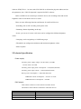
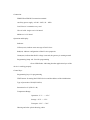
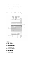
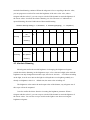
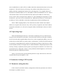
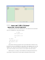
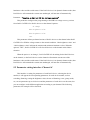
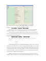
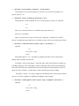
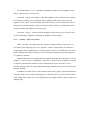
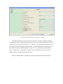
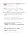
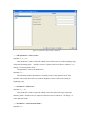
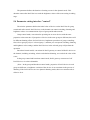
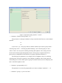
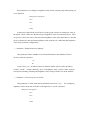
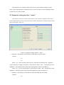
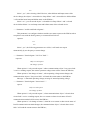
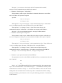
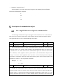
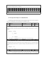
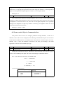
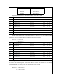
KNX/DALI GATEWAY
User manual
1.General
This manual provides detailed technical information about the KNX/DALI GATEWAY
for users as well as assembly and programming details, and gives the parameters of the
database related instructions. KNX/DALI GATEWAY has achieved the conversion between
DALI protocol and KNX protocol.
Connect the KNX system and DALI system though the interface, using the computer
operating interface it can be set up the two-way communication between the KNX group
address and DALI system, it also can implement other functions like single-address dimming,
switching, setting scenes, groups and broadcasting, it can control 16 scenes, 16 groups and 64
single-addresses.
DALI interface can be connected up to 64 DALI devices. By a communication object,
each DALI devices can perform the function of switching, dimming, brightness value setting
independently. 64 DALI devices in Channels can perform the function of switching, dimming
via the group or broadcasting mode. Each DALI devices can be provided with 16 scenes and
can be assigned to 16 different groups.
1.1DALI System Introduction
There are up to 64 slave units in the same DALI network, and each salve units has a
Short address. A salve unit also can be assigned to a group and exist up to 16 groups at the
same time, and that a salve unit may belong to different groups. Host can also send the
information to all slave units. The main features of DALI protocol: asynchronous serial
communication, 1200 baud, two different wire signal, a DALI BUS can connect 64 salves,
each salve can be addressed individually, but can’t process the two-way communication.
1.2Product and functional description
KNX/DALI GATEWAY - 1 fold is a modular installation device, using EIB BUS
connection terminals to connect to the system. The DALI GATEWAY need an extra voltage
supply to connect to the AC power supply directly. It is able to use the Engineering Tool
Software ETS(ETS2 v1.3 or later) with VD2/VD3 file to allocate the physical address and set
the parameters, but a VD3 file imported is required for EST3 software.
DALI GATEWAY can control up to 64 DALI devices, the switching status and current
brightness value of each DALI devices is visible.
There are same following functions and features for each DALI devices:
--Switching: ON or OFF according to the preset value
--Dimming: dimmer depending on the step
--Scene: you can set 16 scenes, each scene can be configured to different brightness
values
--Grouping: can be assigned up to 16 different groups
--Threshold: can configure the minimum and maximum brightness values
--Status response
2.Technical Specification
Power supply:
Auxiliary power supply voltage: AC100--240V,50~60Hz
AC100--240V,50~60Hz
Auxiliary power input power consumption: <=6W(220V,full-load)
Auxiliary power input Current: <=28mA(220V,full-load)
Device power consumption: <=3W(220V,full-load)
EIB/KNX Current consumption: < 12mA at 30 V DC
EIB/KNX Power consumption: < 360mW
DALI output:
Total number of Devices on the channel: 64 DALI devices
The distance between DALI GATEWAY and DALI devices:
CSA(cross sectional area of Cable):
0.5
0.75
1
1.5
distance between DALI GATEWAY and DALI devices(ms)
120
182
241
315
Connection:
EIB/KNX:an EIB BUS connection terminal
Auxiliary power supply: AC100 - 240V, 50 ~ 60Hz
Load Circuit: 2 terminals every road
CSA of cable: single core 0.2-4.0mm2
Multicore: 0.2-2.5mm2
Operation and display:
Indicator:
Yellow(error): indicate error message of DALI slave
Red(init): indicate configuration of DALI salve properties
Green(run): indicate that DALI voltage is normal, the gateway is running normal
Programming lamp: red: Used for programming
Green LED flashes: indicating that the application layer of the
device is working properly
Control keys:
Programming keys: for programming
TEST button: for testing DALI BUS devices and the address of the initialization
Type of protection: IP 20(EN 60529)
Protection level: 2(EN 61 140)
Temperature Range:
Operation: -5° C ... + 45° C
Storage: -25°C...+ 55°C
Transport: -25°C...+ 70°C
Housing and color: plastic housing, white
Installation: on 35mm DIN rail
Dimensions: 92X113X91MM(H x W x D)
CE standards:
3. Connection and Dimension diagram
①DALI Outputs –
② DALI Outputs +
③ Test/Set Button :
④ Programming LED
⑤ Programming Button
⑥ 230V Auxiliary
⑦ Red LED(INIT)
⑧ Yellow LED(ERROR)
⑩ Green LED(RUN)
4. The Design & Application of The DALI Gateway
Diagram:
AC230V
KNX
DALI-ballast
KNX/DALI Gateway
DALI
DALI ballast
AC230V ( power supply for DALI Gateway only)
Application:
Application
The maximum
communication
object number
The maximum group
address
The maximum united
group address
Dali Gateway, 1fold
235
250
250
Function Introduction
4.1 Switching
If a telegram with the value “1” is received via the communication object” Lamp
burn-in”, all devices on the channel may only be operated 0%(off)or 100% brightness for the
burn-in time set for this parameter. This applies independently of the other dimming, on/off
and light scene brightness values which have been set. The burn-in time has priority over all
other settings. after the burn-in time has elapsed or the function is deactivated(telegram value
of the communication object “Lamp burn-in” equal to “0”,the channel can be dimmed and
programmed light scenes can be accessed.
4.2 Relative Dimming
After a start command is received, the brightness is changed in the defined direction
(upward or downward) with the parameterized speed. Dimming values which are greater than
or less than the max. or min. values will not be set, the parameterized max. or min. value are
retained when dimming continued. When the telegrams is less or equaling to the min. value,
you can program to switch off or retain the brightness of the min. value. Also, when a
telegram with the value“0”,you can set up to switch off the channel or retain the lightness of
the lowest values. It realizes the relative dimming via 4 bit. The max.is“1”indication of
upward dimming, the min“0”indication of downward dimming.
Relative dimming setting:(1~7,downward;0、8retaining(stopping );9~15upward )
Parameter
0
1
2
3
4
5
6
7
Downward
Retaining
No
downward
25
5
73
52
37
14
7
4
dimming
dimming
parameter
8
9
10
11
12
13
14
15
Upward
Retaining
73
52
37
14
7
4
dimming
No upward
25
5
dimming
4.3 Absolute Dimming
8bit telegrams realize the needed brightness via changing the brightness telegrams
(similar the relative dimming) or the brightness scope, a low value and a high value while the
brightness can only changed between this scope, the max.0~the min. ~255.When switching
on the light, it can be set to turn on the light in a delayed time or to brighten gradually to a
already set brightness value in a
default time, the same to the switching off.
The brightness value restrict the total output value of the dimmer, any telegrams out of
this scope will not be outputted.
I can also realize the below function via setting the brightness parameter. When a
telegram with the value“0”,you can set up to switch off the channel or retain the lightness of
the lowest values. You can also set up to switch on the lights or not when receiving the
brightness telegrams.
4.4 Scene
It supports 16 scenes(1-16) to control the DALI device in 8 data bit. You can set up a
brightness value and the dimming time when switching on for each scene. After that, you can
choose any scene you like at any time. The DALI devices in the channel can choose the 16
scenes via the scene order, it can also applies the current brightness in the correspondent
scene.
4.5 Controlling via choosing the devices
DALI devices in the channel can be chosen separately to individually control so that it
can realize the relative dimming, absolute dimming, checking the state of the ballast and the
lamps, and the group address it belongs to, or adding or deleting some of the group address.
Only the DALI devices are in normal condition can they be chosen to control.
4.6 Group Controlling
Every DALI devices in the channel belongs to 16 groups at the same time. And it exists
multiple DALI devices in each group so that you can divide different DALI devices into
different groups and to realize the individual controlling, like switching or dimming.
4.7 Broadcast control
In the broadcast control mode, all the DALI devices in the channel can be switched
on/off or dimmed at the same time, while if the time for dimming is not unified, the Change
in brightness is also not the same.
4.8 Staircase lighting
When the dimmer actuator is used to control the staircase lamps, after the staircase
lighting is activated the lamps should be lit at a certain value, then changing to another value
and after a certain time, it will be switched off.
The staircase lighting function is triggered by switching the button on/off(telegram with
value“1”).
switch control process: a telegram received with the value“1”, the DALI devices will be
the dynamic dimming mode: lamps should be lit at a certain value( set in advance), then
changing to another value and after a certain time(set in advance),a “1”telegram in the hold
phase means that the hold phase will run again(retriggering).When a telegram“0”is received,
the lamps will switch off.(telegram with value“1”means to turn on while telegram with
value“0 means to turn off).
4.9 Report of various state
There are main three faults for the DALI Gateway: the ballast faults, the lamps faults
and voltage failure. The DALI devices will not work under the three above conditions. While
checking the DALI devices, find one or more lamps or ballasts faults, the DALI Gateway will
report it to the EIB bus via the communication object 1bit.But under normal condition, the
DALI Gateway will not check these faults automatically. Once it has the voltage failure of the
communication port, the DALI Gateway will report the faults to the EIB bus.
4.10 EIB and DALI Bus resetting
The DALI Gateway is composed of the DALI bus and the EIB bus, so the DALI
Gateway will only work normally when connecting the 230V and the EIB power supply.
When the EIB bus resetting, it will report switch state and the current brightness value of
DALI devices in the channel. And after the recovery of 230AC voltage of DALI Gateway, it
will check the switch state and current brightness value of DALI devices in the channel and
report to the EIB bus, besides, it will send the number of the DALI devices in the channel to
the EIB bus and check automatically the existing DALI devices having no address.
4.11 LED Display
Green LED: Lights will turn green if the voltage supply is present and will keep it green
if the 220AC voltage supply and communication with KNX bus is normal. While the DALI
Gateway initializes the DALI devices in the channel, green lights turn off. The green lights is
the symbol of the normal function of the DALI Gateway, the normal communication of the
DALI bus and the EIB bus.
Yellow LED : Lights will turn yellow in the event of a DALI fault. And a DALI fault is
a DALI short circuit or a ballast or a lamp fault. Lights will keep yellow under the condition
of the short circuit. While testing the DALI devices in channel via the communication object,
the DALI Gateway will send the fault telegrams of devices to report the lamp fault to the EIB
bus. Then it will test the DALI devices in the channel and the DALI Gateway will work
normally after the yellow lights turn off.
Red LED(D1):The red LED shows the Gateway in various programming mode, please
check it in details below:
The Lights keep red: when the DALI Gateway is assigning address for the device
channel, the green LED turn off while the red LED turn on. And after finishing the assigning
the address, the red LED turn off while the red LED turn on.
The red LED flashes 300ms:1,under the manual operation mode, pressing test
button(2s-5s) to update the data of the DALI Gateway, the red LED flashes.2, while resetting
the DALI bus, the red LED flashes.
The red LED flashes 100ms:1, the red LED flashes while finishing the download of the
data base, and the DALI Gateway are doing the configuration and initialization according to
the data base.2, the red LED flashes while the DALI Gateway is testing the DALI devices.
4.12 Manual Operation
The DALI test button is used to test the DALI equipment.
Short press (20ms - 2S): The DALI Gateway will turn on/off the DALI devices to test
the function of the DALI devices.At the same time, it will report the switch and brightness
state to the EIB bus.
Long press(2s – 5s): it is used to update the data of the DALI Gateway, which will test
the current brightness value, the switch state, the address to know the state of the DALI
devices(operating in the process of installation or updating).If the DALI devices in the
channel have no address, it will be assigned a address while initialization.If the new installed
devices have already the address, then the system will not assign it again no matter this
address is repeated or not.
Long press(>5s): it is used to initialize DALI devices in the channel and assign the
DALI devices automatically from 0.The more devices, the longer time for assigning the
address(during this process, no other operation and the DALI Gateway will not deal with the
telegram of EIB bus). If newly DALI devices have already the DALI address, but the address
is the same with the other installed devices, then it will need to assign DALI address of all the
devices.
If it needs to add new DALI devices in the process of installation, users will need to
connect new DALI devices in the DALI channel individually and assign the address via
object “assigned DALI address”. The DALI Gateway will erase the existing address of the
newly installed devices and it will be no address when the communication object receives the
telegram“0”. The DALI Gateway will assign a new address which follows the previous
address when the communication object receives the telegram“1”.For example, there are 6
DALI devices and their address is 0-5, if the address of the new installed devices is 4. Then it
will disconnect these 6 devices from the DALI bus and erase the address 4 of the newly
devices, and it will be reassigned a new address of 6. After finishing the assignment, it needs
reconnected previous 6 devices in the DALI bus. While the DALI devices is in the state of
no address, it can be controlled via the short test push button of the broadcasting mode.
Notice: While assigning address, if two DALI devices share with the same random
address are assigned at the same time, they will be possibly assigned the same DALI address.
Under this circumstances, it will need to assign the address individually for these two DALI
devices.
4.13 Operating Steps
Before downloading the data base, it will need to initializing devices in the DALI bus.
First, press the test button for more than 5 second, the DALI Gateway will begin to initialize
devices in the bus and assign the address from 0 to 64. After assigning the address, users can
test the devices in the DALI bus (such as object “switch/status”) via the ETS3/EST4 software.
It can test the corresponding device number of each lamp, test if there is DALI devices faults
of each channel; Second, to configure devices and download the configured parameters to the
Gateway; Finally, to update the Gateway data via pressing the test button for 2-5s.Then it can
operate the devices, during this, if there is some problems with the brightness, it will need to
download again the configured parameters.
Notice :if you does not to operate following the above steps, DALI devices will not be
controlled like the preset brightness value.
5. Parameters Setting of ETS System
5.1 Parameter setting interface
In the “General” parameter window, configuration of the basic parameters are effective
for all DALI GATEWAY devices.
Picture 5.1 “General set”
Parameter “Reaction on DALI or EIB bus voltage failure”
“Reaction on DALI
or EIB bus voltage failure”
This parameter shows the action of DALI devices on the channel of DALI GATEWAY
in the case of EIB/KNX bus voltage failure. Options:
No change
Max brightness value
Min brightness value
Off
“No change”
“Max brightness value”;
“Min brightness value”
“Off”
This parameter defines the performed actions on the channel DALI GATEWAY of all
DALI devices in the case of EIB/KNX bus voltage failure, “Max brightness value” and “ Min
brightness value” indicate the maximum & minimum luminance value. When the option is
“OFF”, DALI GATEWAY will close all devices on the channel at this failure situation.
When the option is “no change”, DALI GATEWAY do nothing for the DALI devices
on the channel, so the DALI devices on the channel will maintain current state of the
luminance value and the switch status. If the DALI devices is in dynamic dimmer mode, then
DALI device will maintain the current state unchanged, will not turn off automatically.
Parameter “Reaction on DALI or EIB bus voltage recovery”
This parameter configure after programming or the EIB bus voltage recovery, actions
from DALI GATEWAY to DALI devices on the channel. Options:
No change
Max brightness value
Min brightness value
Off
This parameter defines performed actions of DALI devices on the channel when DALI
GATEWAY or EIB bus voltage returns to the normal condition. “Max brightness value” and
“ Min brightness value” indicate the maximum & minimum luminance value. When the
option is “OFF”, DALI GATEWAY will close all devices on the channel at this failure
situation.
When the option is “no change”, DALI GATEWAY do nothing for the DALI devices
on the channel, so the DALI devices on the channel will maintain current state of the
luminance value and the switch status. If the DALI devices is in dynamic dimmer mode, then
DALI device will maintain the current state unchanged, will not turn off automatically.
5.2 Parameter setting interface ‘Channel A’
This interface is setting for parameters of each DALI device, selecting the device
number, it will appear the corresponding parameters for each device number, such as
switching, dimming, setting the brightness value, the rate of dimming, scene, group, mode,
etc, can set parameters up to 64 devices and the parameters of each device are the same, but
you can configure to the different application according to your demand. The following
parameters for example will be described.
Picture 5.2 “Channel A” (normal)
Parameter “Device Number” Parameter “Device Number”
This parameter is used to select the device number what you want to configure the
DALI device. Options: AO ....A63 correspond to the “Device A0” to “ Device A63”.
Select DALI device properties configured on the channel, when you select different
device, the following parameters need to be reconfigured, and that the following parameters
are correspond for the device properties.
Parameter “Operating mode”Parameter “ Operation mode”
This parameter sets the operating mode of DALI devices Ax(x=0…63).
Options:
Normal
Dynamic
Normal dimming mode used to control the general lighting system, it can be set the rate
of dimming, the brightness value of switches, dimming, setting the brightness value for each
DALI devices, it also can be assigned to multiple scenes number, through the scene function
to call the brightness value be set until the brightness is suitable for the required ambient, the
operation of grouping, normalizing multiple DALI devices to the same group, the groups
can be control of switching and dimming directly.
Dynamic dimming mode is used to control staircase lights, DALI device changes the
brightness values according to the period to achieve Staircase lighting function, such as open
stair lights, output delay for a period of time and turns off automatically. If the dimming mode
has the dynamic attribute, the correspond device are not assigned to a group, thus can not be
the main control, but can be dimming control in the broadcast mode, set the scene value.
Parameter “Brightness value when turned on”
This parameter sets the switch brightness value from Ax(x=0…63) of DALI
devices. When the object “Ax Switch” receives the message “ON”, DALI device will
turn on the lights in this brightness value. Options:
Min physical brightness
10%, 20%,… ,100%,
last brightness value
Select “Min physical brightness”,DALI device turns on the lamp in the minimum
physical luminance value. If this minimum physical luminance value is less than the limited
value, the brightness of the lamp is turned on in the lower limit value. The lower brightness
limit value can be set by the parameter “ Min brightness value”.
If the “10%/.../100%”option is selected, DALI device turns on the lamp with the preset
brightness value. If this preset value is less than the lower brightness limit value, turn on the
lamp with the lower brightness limit value; if this preset value is more than high brightness
limit value, turns on the lamp with the high brightness limit value. The high brightness limit
value can be set by the parameter “Min./Max .brightness value”.
If the “last brightness value” option is selected, DALI devices light up with the last
brightness value what is not “0” of the steady state. When the DALI device is in the dimming
state, the brightness value of this device can’t be detected accurately by the GATEWAY, so
DALI GATEWAY just keep the last brightness value of the DALI device in the steady state.
When DALI GATEWAY does not save the last brightness value, that DALI device will open
with a default brightness value(200).
Note:
The minimum physical brightness value is determined by the physical properties of
DALI device, different models of DELI devices have different physical properties, then what
the minimum brightness value to support is different.
Parameter “Minimal brightness value”
This parameter is used to set the minimal brightness value of DALI devices Ax.
Options:
min. physical brightness
5% , 10%, … ,70%
If the minimum brightness value is less than the minimum physical brightness value,
then the light will be turn on with the minimum physical brightness value as its lower limit
value, this is determined by the technical performance of DALI device.
Parameter “Maximum brightness value”
This parameter is used to set the maximum brightness value of DALI devices Ax.
Options:
30%, 40%, …, 100%
The minimum & maximum brightness value limit the whole light output of DALI
device Ax, the brightness of DALI device only can be adjusted within this range. The
brightness value which is not in this range can not be output, such as 1~255 belong to this
range, the minimum value is 40%, the maximum value is 90%, then its output range is
40%~90%. If the brightness value is 92%, it will not be output. The brightness start to
dimmer directly in the minimum value under the increasing from 0%. On the contrary, the
brightness begin to dimmer with the maximum value under the reducing from 100%.
Through the above two configuration parameters, the threshold of this DALI device is
be set, then in the dimming process, DALI device only can dimmer within this range of
brightness value.
Parameter “Permit lamp to be turned on via dim telegram”
This parameter sets whether it can open the DALI device through the relative function in
the case of the brightness value of DALI device is 0. Options:
No
Yes
If the brightness value of this DALI device is in the inactive state, when selecting “yes”,
DALI device can be open by the communication object of the relative dimming function, the
brightness value will not be 0 any longer.
On the contrary, when “no” is selected, this DALI device in the inactive state can not be
open via the communication object of the relative dimming function, it can not be relative
dimming control.
Parameter “Permit lamp to be turned off via dim telegram”
This parameter sets whether it can close the DALI device through the relative function
in the case of the brightness value of DALI device is not 0. Options:
No
Yes
When this DALI device is in the open state, the brightness value is not 0, when “yes”is
selected, DALI device can be closed via the communication object of the relative dimming
function. When the brightness value of DALI device reaches the minimum brightness value,
close the device immediately.
On the contrary, when “no” is selected, DALI device can not be closed via the
communication object of the relative dimming control. Then this device only can be adjusted
in the minimum brightness value.
Note: The above two parameters have no effect to the relative dimming on the mode of
setting of operations and broadcast control. When the devices on the channel are setting of
operation and controlling of broadcast, the relative dimming function of DALI GATEWAY
can be used to high light gradually the DALI device from the off state or low light it from the
open state until the close state.
——Parameter “Dim period to reach turn on brightness”
This parameter defines the duration for the DALI devices Ax transfer the current
brightness values to the target brightness value, that is dimming rate, adjusted the light by a
gentle gradient. Optional:
Immediate
0.7s
2s
…
90s
It ‘s certain for the dimming time. No matter dimming from 100% to 60%, or to 0%, the
duration of dimming is the time of the parameter preset. For example, if the parameter is
preset to 4s, then the dimming time is always 4s, from 100% to 60% or from 100% to 0%.
No matter in what way to switch the light, or dim the light, such as switches, scenes,
dimming, adjust the brightness values, and so on, the duration of the adjustment is defined by
the parameter.
Note : Due to differences between the DALI devices, there are some differences for
dimming time parameters.
Configuration of DALI device scene :
Each DALI device can be configured with 16 different scenes, the following two
parameters are used to configure the scenes of DALI devices Ax.
——Parameter “Scene Number”
The parameter is to select the scenes to be set, optional: 1-16
This parameter defines the brightness value of the DALI devices to be configured in
16 different scenes. When selecting different scenes No., the following parameters need to be
reconfigured.
——Parameter “Light scene value”
This parameter defines the scene brightness value of the DALI devices to meet different
brightness values in different needs. Optional:
OFF
10%
…
100%
No change
When the option from "off" to 100%, DALI gateway has configured brightness values
for different scenes, the brightness be allocated among threshold.
When the option is "no change", the DALI gateway will call the scene, meanwhile the
DALI devices are not affected, keeping the current brightness value and switch status.
The default option is "no change", DALI gateway needs to store the current luminance
value as the scene. Then the device will adjust the brightness value the next time you call the
scenes.
( Notes : For each device in DALI protocol, there are 16 scenes which can distribute
different brightness values. When Scene Database Configuration Optional configuration is"
no change ", which means DALI gateway send called scene DALI command, DALI device is
not responding. While implementation of dynamic mode is through called scene DALI
command to change DALI device brightness value. When the scene is set to " no change ",
then the brightness of the device won’t change in dynamic mode )
Configuration of DALI device Group:
Each DALI devices can be assigned to as many as 16 different groups, we can operate
switching, dimming and the brightness value setting of the each group of DALI gateway.The
parameter interface 5.2 only sets the groups devices belonging to. As to if enabled the group
control, please refer to the parameter settings of interface 5.4.
——Parameter “Group Number” Parameter " Group Number "
The parameter is to select the group you want to set, you can set a maximum of 16
groups, options: 1-16
——Parameter "device Ax belong to Group y[y=1...16 ]"
This parameter is used to add the device Ax to the group you want to set. Optional:
Yes
No
Select "yes", the DALI Devices Ax added to the group will be set ;
Select "No", not added.
Object " selected device remove from Group " and object " selected device Add to
Group " to modify the group DALI devices belong to, and it will be saved when power down.
——Parameter " Send switch status response ( object " switch/status " ) "
Optional:
No
Only if value change
Always
The default option is " no ", regardless of whether the DALI devices switch status
change, status messages will not sent.
For option " only if value change ", when the status value of DALI devices changes by
switching, dimming, scene controlling, if status is stable,the status will be sent immediately.
Due to the relatively slow communication rate of DALI protocol and the number of devices
on the bus, there will have a certain delay for the switch status messages sending.
For option " always ", it is always reported to the EIB bus if the current status of DALI
devices is received, regardless of whether the brightness values change.
——Parameter " Send brightness status response ( object " Brightness value/status " ) "
Optional:
No
Only if value change
Always
The default option is " no ", regardless of whether the DALI devices brightness values
change, status messages won‘t be sent.
For option " only if value change ", when the brightness value of DALI devices changes
by switching, dimming, scene controlling. if the brightness reach to the preset value, the
brightness value will be sent immediately. Due to the relatively slow communication rate of
DALI protocol and the number of devices on the bus, there will have a certain delay for the
messages sending and brightness value messages.
For option " always ", when the current brightness value messages are received, it will
be sent immediately, regardless of whether the brightness values change.
5.2.1 "
dynamic " mode of operation
Under " dynamic " operating mode, the parameter settings interface of the device Ax
is as shown in the following figure, the " dynamic " mode is used primarily to situations of
controlling the stairs of lighting.The so-called dynamic model is to call different scene values
in three different time stages, which has to been configured conjunction with the parameters
of " dynamic " interface.
When the DALI devices configured with a dynamic dimming mode, DALI device starts
sending " 1 " by the object " switch/status " of the device. DALI devices in dynamic mode can
be relatively and absolutely dimmed via the communication object. DALI devices in a
dynamic dimming mode can control dimming through communication objects of relative and
absolute dimming .
In addition, the DALI devices in the dynamic mode can be group assigned and cannot be
selected to control, in the relative dimming process the DALI device can be on and off in this
mode. In this mode, DALI devices can implement the stair lights function, and can work as an
ordinary light.
Figure 5.2 parameter settings interface " channel A" ( dynamic)
If the dynamic dimming mode is selected, DALI devices will be in dynamic dimming
working mode, similar to the stair lighting function. Once the dynamic mode of DALI devices
starts, the device will call the first scene of " dynamic " , then starting call the second scene
after a period, then automatically shut down after a period, and brightness value changes to 0.
Meanwhile, in dynamic dimming mode, message " 0 " can be sent by the communication
object " switch/status " of the device, the DALI device will shut down directly, not after
dimming process, dynamic dimming mode ends.
Dynamic dimming mode is divided into 5 phases, as shown in the following figure :
When DALI devices receive an " on " command, dynamic dimming mode starts,
implemented as follows : ( Suppose no.9 begins scenes configuration, no.10 end scene
configuration)
1. " Scene 9 " of DALI devices is called by DALI gateway, the current brightness values of
the DALI device gradually turn to " scene 9 ". The dimming time of the process can be set by
the parameter " Dim period to reach turn on brightness resp.Off state ".
2. The duration of " scene 9 " of DALI devices can be figured via parameters " Start scene
hold time ", the brightness value of the device will continue for some time, then enter to next
Status.
3. For " scene 9 " gradually turn to the " scene 10 " of DALI devices, the time required is the
dimming time set in parameter " Dim period to reach turn on brightness resp.Off state ".
4. DALI devices " scene 10 " will keep the brightness values for some time, duration is
configured by the parameter " Start scene hold time ".
5. When duration of " scene 10 " of
DALI devices ends, the device will get dark gradually
until shut down, then dynamic dimming mode ends.
Note: There can’t be too many communication objects in the same group address,
because Baud rate of DALI protocol is only 1.2k, which is relatively lower. There allow
maximum 7 communication objects connected to the same
group address.
5.3 Parameter setting interface " Dynamic "
The parameters window is to configure the scene and duration of DALI Gateway
dynamic controlling mode.
Figure 5.3 parameter settings interface "Dynamic"
——The parameter " Start scenes "
Optional: 1, 2,,,,,, 16
This parameter is used to select the called scenes of DALI device of the beginning stage
in dynamic dimming mode. And the scene No. Option of the DALI device cannot be " no
change " if select dynamic mode.
The parameter " Start scene hold Time "
Optional: 1s,......
The parameter defines the duration of starting a scene in the dynamic mode. This
duration counts after DALI devices reach the brightness values of the scene setting in
beginning stage.
——Parameter " End Scene "
Optional: 1,,,,,, 16
This parameter is used to select the called scene in the end of the stage in dynamic
dimming mode. And the scene No. Option of the DALI device cannot be " no change " if
select dynamic mode.
——Parameter " end scene hold Time "
Optional: 1s......
The parameter defines the duration of starting a scene in the dynamic mode. This
duration counts after DALI devices reach the brightness values of the scene setting in ending
stage.
5.4 Parameter setting interface "control"
The window parameter defines the initial value of devices on the DALI bus for group
control and radio control. DALI devices on the channel can control switching, dimming and
brightness values via communication object of group and broadcast mode.
Group control mode, convenient for operating one or more devices with the same
properties at the same time. If properties of devices in the same group are different, there will
be different dimming effects for DALI devices. Implement procedures of group controlling:
first select a group by object " selected group ", and then you can operate switching, dimming
and brightness value settings, and the DALI devices in the selected group will perform the
operation.
Broadcast Control model, convenient for DALI gateway to control all DALI devices on
the channel, including switching, relative and absolute dimming, save and cal the value of the
scene.
In the group control and broadcast control mode, DALI gateway can turn on of off
DALI devices via relative dimmable.
( Note : In the group and broadcast control mode, properties of DALI devices in each
group are different, so brightness variation of the devices is not consistent in the process of
dimming. If the DALI devices are in a dynamic dimming mode, these two control modes is
effective for it.
Figure 5.4 parameter setting interface " control "
——Parameter " Enable control groups[1-16 ] "
This parameter is configured whether to Group control the DALI devices on the channel.
Optional:
No
Yes
If you select " yes ", the group control is enabled, and the object used to group control "
selected group on/off ", " selected group REL.Dimming " and " Selected group set value "
will be visible. You can operate switching, dimming and brightness value setting of DALI
devices in the selected group through these objects. If the group is assigned to the device,
please refer to configuration of the DALI device group in parameter interface 5.2.
The following two parameters is to configure devices brightness value of a switching
selected group. First select a group No., then configure a brightness value for the group No.
when turning on or off. So when operate a group of switches control, devices in the group will
turn on with this brightness value.
——Parameter " group number[1-16 ] "
The parameter is to select the group number you want to configure. Optional: 1......16
——Parameter " group ( x ) power on Value "
The parameters is to configure a brightness value for the selected group when turning on
or off. Optional:
Min physical brightness
10%
20%
…
100%
In the group control mode, DALI devices in the group will turn on with power value in
the option. ( Note : Make sure that the range of brightness values of each DALI device, if the
over power is above the value of the maximum brightness value of the DALI Device, then the
device will turn on in the maximum brightness value of the device, rather than the brightness
value of the parameter configuration)
——Parameter " Enable all devices lighting "
This parameter defines whether to activate the Broadcast Control Model of DALI
devices on the bus. Optional:
No
Yes
If you select " yes ", broadcast control is enabled, and the objects used to broadcast
Control " on/off ", " relative dimming " and " set brightness value " will be visible. And you
can operate switching, dimming and brightness value setting of all devices on the channel.
——Parameter " All device power on Value "
This parameter is visible when the last parameter selected to " yes ", for configuring
brightness values when turn on the device through object " on/off ".Optional:
Min physical brightness
10%
20%
…
100%
The parameter is to configure all the DALI devices on the channel turning on in the
preset value of the parameter in broadcast mode. In order to achieve a DALI dimming control
for DALI device on the Channel.
5.5 Parameter setting interface " status "
This interface is used to set various status reports, such as Switch / brightness status report
for the selected device, the error report of lamps or ballasts, the KNX bus voltage exception report,
short circuit reports, and so on.
Figure 5.5 parameter setting interface " status "
——Parameter " On change of selected device send status on/off and Value "
Optional:
Yes
No
Select " yes ", after selecting a DALI devices, when the switch status and brightness
values of the device change, the objects " selected device status " and " selected device read
brightness " will send the latest switch status and brightness values to the EIB bus ;
Select " no ", you can use the Object " selected device status " and " selected device read
brightness " reads the current switch status and brightness of the selected device.
——Parameter " On change of selected device send fault lamp and fault ballast
Optional:
Yes
No
Select " yes ", after selecting a DALI devices, when ballasts and lamps status of the
device change, the objects " selected device lamp failure " and " selected device ballast failure
" will send the latest lamp and ballast status to the EIB bus ;
Select " no ", you can use the object " selected device lamp failure " and " selected
device ballast failure " to read lamp status and ballast status of the selected device.
——Parameter " enable send fault telegrams "
This parameter is to configure whether send the error status reports to the EIB bus when
exception occurs with the DALI gateway or connected DALI device.
Optional:
Yes
No
Select " yes ", the following parameters are visible, it will send error report
automatically by use the query or status change.
——Parameter " Send telegram " 230 VAC fault " "
Optional:
Only on read request
On change of status
When option is " only on read request " when communications object " bus power fault
" receive a reading request, the current operation voltage status will be sent to the EIB bus;
When options is" On change of status ", when operating voltage status changes, the
communications objects " bus power fault " will send the current status to the EIB bus.
Message ‘1’:abnormal operating voltage ,message‘0’:normal operating voltage
——Parameter " Send telegram " short circuit " "
options:
Only on read request
On change of status
When option is " only on read request ", when communications object " electric short
circuit fault " receive a reading request, the over current or short circuit status of DALI
communication terminal will be sent to the EIB bus ;
When options is " On change of status ", when the over current or short circuit status of
DALI communication terminal changes, the communications object " electric short circuit
fault " will send the current status to the EIB bus ;
Message ‘1’:over current or short circuit on DALI communication terminal;
message‘0’:DALI communication terminal back to normal
——Parameter " Send telegram " ballast fault " "
This parameter is used to report if the ballast is abnormal, when one or more ballast
don’t work, there will report the exception.
Optional :
Only on read request
On change of status
When option is " only on read request ", when communications object " ballast fault "
receive a reading request, the status of ballast will be sent to the EIB bus ;
When options is " On change of status ", when ballast status changes, the
communications object " ballast fault " will send the current status to the EIB bus ;
Message ‘1’:one or more ballasts abnormal;message‘0’:ballasts normal
——Parameter " Send telegram ‘lamp fault’ "
This parameter is used to report whether there is the lamps exception, when there are
one or more lamps not working or not connected, then will report the exception. Optional:
Only on read request
On change of status
When option is " only on read request ", and communications object " lamp fault report
" receive a reading request, the status of the lights will be sent to the EIB bus ;
When options is " On change of status ", and the status of lights change, the
communications object " lamp fault report " will send the current status to the EIB bus;
Message ‘1’:one or more lamps abnormal;message‘0’:lamps normal.
——Parameter " cycle period between DALI and EIB bus "
The parameters is used to set the EIB bus and the DALI bus to communicate with each
other. Optional:
Yes
No
Select " yes ", if the EIB bus and DALI bus communication fails, the communication
object " tele. Communication " will send the message " 1 " to the EIB bus circularly. If the
communication is normal, a message " 0 " will sent to the EIB bus. There won’t be circular
sending when the communication is normal, only when a communication failure sending
messages circularly; cyclical intervals can be set by the following parameter " Transmission
Control timeout ".
——Parameter " period of time "
This parameter is to set the interval for message circular sending between EIB and
DALI bus communication. Optional:
5s
10s
…
12h
6. Description of communication object
6.1
For a single DALI device object of communication
The following communication object only applies to the 64 DALI devices on the channel A.
Each device has a separate switch object, relative dimmer objects and absolute dimmer objects,
The single DALI device can be controlled through these objects.
NO.
Function
Object Name
0~63
Switch/status
Ax (x= 0
...
63) switch
Type
Flags
1bit
C,W,T
This communication object is used to switch DALI device.If the device receives the report
whose logic value is "1" it will be open according to the predetermined value, if it receives value
of "0",then turn it off. At the same time the communication object also sends the current switch
state to EIB bus, if the brightness value is greater than 0, the communication object sends a
message "1" to the bus; if the brightness value is 0, sends a "0" to the bus,the specific sending way
se definite by the parameter "Send the switch status response",please refer to the description of the
parameters in section 5.2.1 to this parameter for details.
Message:
1——on
0——off
64~12
7
Relative Dimming
Ax (x= 0
...
63) Relative Dimming
4bit
C,W
Through the communication object to light up or down, when the input values is 1~7 means
dimming the light up, in this range the larger value, the smaller margin to dimmer the light down,
when the value is 7 represents the maximum amplitude of dimming the light down, 0 is to stop
dimming; When the input values is 9~15 shows dimming light up. The higher value in this range,
the smaller margin to dimmer the light up, when the value is 9 represents the maximum amplitude
of dimming the light up, value of 15 means the minimum amplitude, 8 is stop to dimming.
Message:0…15
128~1
91
Brightness
value/status
Ax (x= 0
...
63) Brightness
1byte
C,W,T
The communication object by receiving the brightness value to open or close the Dali
devices,If the brightness of the received value greater than 0, then turn on the lights, if receive the
brightness value "0", then turn off the lights.At the same time the communication object will also
send the brightness values of the current state to the EIB bus.the specific way to send by the
parameter “Send brightness status response” definition,please refer to the description of the
parameters in section 5.2.1 to this parameter for details.
Message: 0…255 (0…100%)
6.2 For each DALI device object of communication
The following communication object can switch ,dimmer and set brightness value the
selected DALI device directly, adding and deleting from groups which they belongs.
NO.
Function
Object Name
Type
Flags
192
Device select
Channel A
1byte
C,R,W
Through this object selects to control the DALI device. Before the new value is written to the
object,,the device will remain in the selected state. When the Bus power supply is restored, there is no
device is in the selected state.
Message:1—— Device A0 is selected
……
64——Device A63 is selected
Note: 0 and 65... 255 deselect the selected device, mean no device in the selected state.
193
Selected Device On/Off
Channel A
1bit
C,R,W
The communication object is used to switch the selected DALI device. The selected device through
this object can be switched. If the object receives the report whose logic value is "1", the selected DALI
device according will be open according to the predetermined value, "0" is turned off.
Message:1——on
0——off
194
Selected Device Rel. Dimming
Channel A
4bits
C,W
Through the communication object to light up or down, when the input values is 1~7 means
dimming the light up, in this range the larger value, the smaller margin to dimmer the light down, when
the value is 7 represents the maximum amplitude of dimming the light down, 0 is to stop dimming;
When the input values is 9~15 shows dimming light up. The higher value in this range, the smaller
margin to dimmer the light up, when the value is 9 represents the maximum amplitude of dimming the
light up, value of 15 means the minimum amplitude, 8 is stop to dimming.
Message:0…15
195
Selected Device Set Value
Channel A
1byte
C,W
The communication object open or close the selected DALI device by receiving the brightness
value, If the received brightness values is higher than 0, open, if the received brightness value is "0",
then close.
Message :0…255 (0…100%)
196
Selected Device Status
Channel A
1bit
C,R,T
The communication object is the switch of DALI device status which is selected in the current
report for the bus;If the parameter interface parameters of 5.5 “On change of selected device send status
on/off and value” Option is "No",do not send switch status report,But you can read the current selected
DALI device switch state, on the contrary, the options for "yes", if the switch state of selected DALI
device changes, it immediately to send the current state of the switch to the bus.
Message:1——on
0——off
197
Selected Device Read Brightness
Channel A
1byte
C,R,T
The communication object is the brightness of DALI device status which is selected in the current
report for the bus;If the parameter interface parameters of 5.5 “On change of selected device send status
on/off and value” Option is "No",do not send brightness status report,But you can read the current s
elected DALI device brightness state, on the contrary, the options for "yes", if the brightness state of
selected DALI device changes, it immediately to send the current state of the brightness to the bus.
Message:0…255 (0…100%)
198
Selected Device Lamp Failure
Channel A
1bit
C,R,T
The communication object is the amps of DALI device error which is selected in the current
report for the bus;If the parameter interface parameters of 5.5 “On change of selected device send
Fault Lamp and Fault Ballast” Option is "No",do not send the lamps of DALI device error
report,But you can read the current selected the lamps of DALI device error value on the contrary,
the options for "yes", If the lamps of the selected DALI device error value changes, it immediately
to send the current state of the lamps to the bus.
Message:1——The lamps of the selected equipment damage or not connected
0——The lamps of the selected equipment is normal
199
Selected Device Ballast Failure
Channel A
1bit
C,R,T
The communication object is the ballasts of DALI device error which is selected in the current
report for the bus;If the parameter interface parameters of 5.5 “On change of selected device send
Fault Lamp and Fault Ballast” Option is "No",do not send the l ballasts of DALI device error
report,But you can read the current selected the ballasts of DALI device error value on the contrary,
the options for "yes", If the ballasts of the selected DALI device error value changes, it immediately
to send the current state of the ballasts to the bus.
Message:1——The ballast for the selected equipment damage
0——The selected equipment ballast is normal
200
Selected
Device
Group(x=1…16)
Remove
from
Channel A
1byte
C,W
Through this object can select DALI device is removed from the group Gx. When using this
object, it need confirm with DALI device is selected.
Message:1—Delete the selected device to Group 1
…
16—Delete the selected device to Group 16
201
Selected
Device
Group(x=1…16)
Add
to
Channel A
1byte
C,
W
Through this object can select DALI device is added to the group Gx, when using this object,
it need confirm with DALI device is selected.
Message:1——Add the selected device to Group 1
…
16——Add the selected device to Group 16
202
Selected Device Own Groups
Channel A
2bytes
C, R
Through this object can be queried by the selected DALI device belonging to a group. Each bit
represents one of the group, every bit of the value of "0" does not belong to the group, as "1"
belongs to the group. If the object's value is 0,the DALI device does not belong to any
group.Specific message format is as follows:
Bit15
Bit14
Bit13
Bit12
Bit11
Bit10
Bit9
Bit8
Bit7
Bit6
Bit5
Bit4
Bit3
Bit2
Bit1
Bit0
G8
G7
G6
G5
G4
G3
G2
G1
G16
G15
G14
G13
G12
G11
G10
G9
Note:Group short for G
6.3 Group control object of communication
The following communication object is used to realize the group control of DALI equipment,
such as for selected group of switch, dimming, set the brightness value.
NO.
Function
Object Name
Type
Flags
203
Selected Group
Channel A
1byte
C,R, W
By setting up to the object set of control group of devices,before the new value is written to
the object, the device will remain selected state. Bus power supply is restored, there is no device is
selected.
Message:1——Group 1
2——Group2
…
16——Group16
Note: 0 and 17... 255 deselect the device, mean no device in the selected state.
204
Selected Group ON/OFF
Channel A
1bit
C,W
The communication object is used to switch the selected DALI device. Through the
communication object receives switch order, If receive the logical value of "1" message, belong to
the selected group of DALI devices is opened according to the predetermined value, "0" switch is
closed.
Message:1——on
0——off
205
Selected Group Rel. Dimming
Channel A
4bits
C,
W
Through the communication object light up or down with Select device,When the input
values for 1~7 is down light, The greater the value in this range, the smaller to cut the amplitude
of light, to 1 to downgrade the sharpest light, for at least 7,0 is to stop the dimmer; When the input
values for 9~15 is up light, The greater the value in this range, the smaller to cut the amplitude of
light,to 9 to downgrade the sharpest light, for at least 15, 8 is to stop the dimmer.
Message:0…15
206
Selected Group Set Value
Channel A
1byte
C, W
This communication object by receiving brightness values to open or close the Dali device
belongs to the group,If the brightness of the received value greater than 0, then turn on the light, if
the brightness of received values of "0", then turn off the lights,It depends on the parameter
Settings of the brightness of light. Pay attention to the range of brightness values are in set
between the minimum and maximum.
Message :0…255 (0…100%)
6.4 Scene control object of communication
Every DALI device scenes can configure parameters through database, A total of 16
different scenes value can be configured, The following communication object can be used to
recall and store the DALI device’s 16 different scene value, there are 1 bit and 1 byte in two ways.
Whether 1 bit or 1 byte, the realization of function is the same, just according to the actual
application to choose a more suitable object type.
NO.
Function
Object Name
Type
Flags
210
Control scenes
Light scenes 1 … 16
1byte
C,
W
Through the communication object, DALI device calls and stored in the form of 1 byte,16
scene can be controlled by this object. The scene of the message are defined as follows:
Set a 1 byte instructions for binary code:MXSS SSSS
M : 0 ——recall scene
1 ——recall scene
X : unused
S: scene NO.(1 . . . 16 )
Concrete are defined as follows:
KNX 1-byte Message
0or64
1or65
2or66
…
meaning
recall scene 1
recall scene 2
recall scene 3
…
15or79
128or192
129or193
130or194
…
143or207
recall scene 16
store scene 1
store scene 2
store scene 3
…
store scene 16
Note: when the bus electricity off, The new setting value will be saved.
211
Recall Scene 1/2(X/Y)
Scene 1/2
1bit
C,
W
212
Recall Scene 3/4
Scene 3/4
1bit
C,
W
213
Recall Scene 5/6
Scene 5/6
1bit
C,
W
214
Recall Scene 7/8
Scene 7/8
1bit
C,
W
215
Recall Scene 9/10
Scene 9/10
1bit
C,
W
216
Recall Scene 11/12
Scene 11/12
1bit
C,
W
217
Recall Scene 13/14
Scene 13/14
1bit
C,
W
218
Recall Scene 15/16
Scene 15/16
1bit
C,
W
Through these communication object, DALI device to call scene1 bit. The brightness values
of the scene will open up DALI device according to the preset parameters.
Message:0——Recall Scene X
1——Store Scene Y
219
Store scene 1/2 (X/Y)
Scene 1/2
1bit
C,
W
220
Store scene 3/4
Scene 3/4
1bit
C,
W
221
Store scene 5/6
Scene 5/6
1bit
C,
W
222
Store scene 7/8
Scene 7/8
1bit
C,
W
223
Store scene 9/10
Scene 9/10
1bit
C,
W
224
Store scene 11/12
Scene 11/12
1bit
C,
W
225
Store scene 13/14
Scene 13/14
1bit
C,
W
226
Store scene 15/16
Scene 15/16
1bit
C,
W
Through these communication object, DALI device stored in the form of 1 bit scene. It can
be stored in the current brightness values of the DALI device to the scene. As the new setting
value, will take the new setting value open DALI device to the next call.
Message: 0——Store scene X
1——Store scene Y
Note: when the bus electricity off, the new setting value will be saved.
6.5 Communication object in whole channel
NO.
Function
Object Name
Type
Flags
207
On/Off
Channel A
1bit
C,
W
Through the communication object, all the DALI device can perform on and off at the
channel A, it means to through broadcasting mode control connection of the DALI device on
channel A. If the received message as "1" The DALI device opens is connected on channel A
according to the predetermined value, the received message as "0", then closed.
Message: 1——on
0——off
208
Relative Dimming
Channel A
4bit
C,
W
Through the communication object to light up or down with the selected device,When the
input values for 1~7 is down light, The greater the value in this range, the smaller to cut the
amplitude of light,to 1 to downgrade the sharpest light, for at least 7,0 is to stop the dimmer;
When the input values for 9~15 is up light, The greater the value in this range, the smaller to cut
the amplitude of light, to 9 to downgrade the sharpest light, for at least 15, 8 is to stop the dimmer.
Message:0…15
209
Set Brightness Value
Channel A
1byte
C, W
Through the communication object can receive brightness values to open or close DALI
device on the channels A, If the brightness of the received value greater than 0, then turn on the
light, if receive the brightness values for "0, is to turn off the lights. Pay attention to the range of
brightness values are in set between the minimum and maximum.
Message:0…255 (0…100%)
227
Telegram. Fault Ballast(s)
Channel A
1bit
C,R,T
Through the communication object report channels DALI ballast device error status on the
channel A, If detected one or more of the DALI ballast device has the damage, then the object has
a value of "1", normal is "0".
Message: 1 —— One or more of the ballast is damaged
0 —— Ballast is normal
228
Telegram. Fault 230 VAC
Channel A
1bit
C,R,T
Through the communication object report 230 v operation voltage is normal or not, If the operating voltage
is abnormal, the object has a value of 1; On the contrary, normal to 0.
Message: 1 —— 230V Abnormal operating voltage
0 —— 230V Normal operating voltage
229
Telegram. Fault Lamp(s)
Channel A
1bit
C,R,T
Through the communication object report Lamps of DALI device error status on the channel .If lamps and
of DALI device didn't answer the phone or damaged on the channel A,then the communication object has A value
of "1",Normal to "0".
Message: 1—— One or more of the lamps is damaged or doesn't answer
0—— The normal work of lamps
230
Telegram. Electric Short Circuit
Channel A
1bit
C,R,T
Through the communication object report on channel A of the DALI communication terminal flow or short
circuit condition. such as, communication occurs at the short circuit ,the communication object will send a "1" to
the EIB bus error status, communication end back to normal, send a message to the bus of "0".
Message: 1 —— DALI communication flow or short circuit
0 —— DALI communication port is normal
231
Telegram. Communication
Channel A
1bit
C,R,T
Through the communication object report on channel A DALI device can receive the KNX message, if it
can normal communication, then the communication object values is "0", communication failure is "1".
Message: 1—— EIB and DALI Bus communication failure
0—— EIB and DALI
232
Detect
Bus communication normal
Ballasts
Channel A
1bit
C, W
The communication object is used to detect the ballast and lamps and of damage of the DALI device on
DALI bus.
Message: 1 —— Test
0 —— Unused
Through the communication object, DALI gateway will detect the lamps of DALI bus device. At the same
time, ballast condition will be the total number of DALI device is used to the EIB bus o n DALI bus issued a
report. If there is abnormal on detect DALI bus Device, the DALI gateway will prompt, yellow light, will pass
through the “Device Number "to send a message.
At the same time, in DALI bus gateway detect DALI device, the red light will blink. When testing is
completed, DALI gateway is not found to have abnormal equipment, the green light, if it is abnormal, the yellow
light, but DALI gateway can still be normal operate.
233
Assigned DALI Address
Channel A
1bit
C, W
Through the communication object of "assigned DALI address " can allocate DALI address,Object receives
a message "0", to erasure all the address of DALIS device on the channel, after erasing DALI device is in a state of
no address, are not separately to control, only can operate on the broadcast control mode;Received a message "1",
DALI gateway detect if there is no address of DALI device on channel , if there is unallocated address, DALI
gateway will detect a not used in the distribution of DALI address. For example, 6 DALI devices are connected,
the address is 0-5, if the new device address is 4, 6 DALI devices put before disconnect from the DALI bus, then
through this object erase new device address, to assign a DALI address, the address will get 6, distribution after the
6 DALI original device connected with DALI bus.
Message: 1—— Give not DALI address to device allocation of unused DALI addresses
0—— Erasure channels of DALI device address
The object types is 1 byte at present.
When the erasure channels DALI address of the device, due to the DALI equipment is in a state of no
address, then the DALI gateway can only to broadcast control channel device.
234
Device Number
Channel A
1byte
C, T
The communication object used to report the number of the DALI device on a channel, and detect the state
of DALI device.DALI gateway in electrical reset will be through the communication object report on the number
DALI device on a channel. In the process of detection of DALI equipment will send abnormal condition of the
DALI device through the object, which can eliminate the bus has been abnormal device.In general, In the process
of initial installation will only be used in the process of the communication object report the DALI devices on the
channel usage.
Message:
Set a 1 byte instructions for binary code:MXSS SSSS
When MX is 0, SSSSSS said the number of channels on all of the DALI devices
When MX is not 0, SSSSSS said the number of abnormal DALI equipment.
M --------1 Said the lamps of the DAIL device has been damaged.
X---------1 Said the DALI ballast has been damaged.