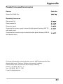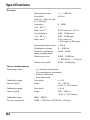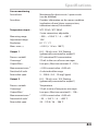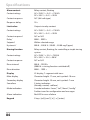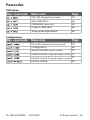
1
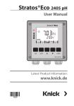
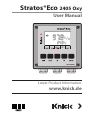
Stratos®Eco 2405 Oxy User Manual Latest Product Information: www.knick.de Warranty Defects occurring within 3 years from delivery date shall be remedied free of charge at our plant (carriage and insurance paid by sender). Sensors, fittings, and accessories: 1 year. Subject to change without notice. Return of Products Under Warranty Please contact our Service Team before returning a defective device. Ship the cleaned device to the address you have been given. If the device has been in contact with process fluids, it must be decontaminated/disinfected before shipment. In that case, please attach a corresponding certificate, for the health and safety of our service personnel. Disposal Please observe the applicable local or national regulations concerning the disposal of “waste electrical and electronic equipment”. Knick Elektronische Messgeräte GmbH & Co. KG Beuckestraße 22 14163 Berlin Phone: +49 (0)30 - 801 91 - 0 Fax: +49 (0)30 - 801 91 - 200 Internet: http://www.knick.de [email protected] 2 Table of Contents Safety Information.......................................................................... 5 Intended Use.....................................................................................................7 Registered Trademarks..................................................................................7 CD-ROM..............................................................................................................8 Safety Instructions..........................................................................................8 Quickstart Guides............................................................................................8 Overview of Stratos Eco 2405 Oxy............................................... 9 Assembly.........................................................................................10 Package Contents..........................................................................................10 Mounting Plan................................................................................................11 Pipe Mounting, Panel Mounting..............................................................12 Installation and Connection........................................................14 Installation Instructions..............................................................................14 Terminal Assignments.................................................................................14 Wiring Example..............................................................................17 Protective Wiring of Relay Outputs........................................................18 User Interface and Display..........................................................20 Operation: Keypad........................................................................22 Safety Functions............................................................................23 Sensocheck, Sensoface Sensor Monitoring.........................................23 GainCheck Device Self-Test.......................................................................23 Automatic Device Self-Test........................................................................23 Hold Mode.......................................................................................................24 Configuration.................................................................................26 Menu Structure of Configuration............................................................27 Overview of Configuration Steps............................................................28 Output 1...........................................................................................................30 Output 2...........................................................................................................38 Correction........................................................................................................44 Calibration Mode...........................................................................................46 3 Table of Contents Alarm Settings................................................................................................48 Limit Function.................................................................................................50 Controlling a Rinsing System....................................................................52 Connecting a Rinsing System...................................................................53 Parameters......................................................................................54 Factory Settings of Parameters................................................................54 Parameters – Individual Settings.............................................................56 Calibration......................................................................................58 Calibration to Percent Saturation (SAT), in Water..............................60 Calibration to Concentration (Conc), in Air ........................................62 Zero Calibration ............................................................................................64 Product Calibration .....................................................................................66 Temp Probe Adjustment..............................................................69 Measurement.................................................................................69 Diagnostics Functions..................................................................70 Error Messages (Error Codes)......................................................72 Calibration Error Messages.........................................................74 Operating States............................................................................75 Sensoface........................................................................................77 Appendix.........................................................................................81 Product Line and Accessories...................................................................81 Specifications..................................................................................................82 Approvals – Canada......................................................................................88 CSA Control Drawing...................................................................................90 Index................................................................................................92 Passcodes........................................................................................96 4 Safety Information Safety information – Be sure to read and observe the following instructions! The device has been manufactured using state of the art technology and it complies with applicable safety regulations. When operating the device, certain conditions may nevertheless lead to danger for the operator or damage to the device. Caution! Commissioning must be carried out by trained experts. Whenever it is likely that protection has been impaired, the device shall be made inoperative and secured against unintended operation. The protection is likely to be impaired if, for example: • the device shows visible damage • the device fails to perform the intended measurements • after prolonged storage at temperatures above 70°C • after severe transport stresses Before recommissioning the device, a professional routine test in accordance with EN 61010-1 must be performed. This test should be carried out at the manufacturer's factory. Caution! Before commissioning, make sure that the transmitter may be connected with the other equipment. 5 6 Intended Use Stratos Eco 2405 Oxy is used for dissolved oxygen and temperature measurement in biotechnology, pharmaceutical industry, as well as in the field of environment, food processing, and sewage treatment. The sturdy molded enclosure can be fixed into a control panel or mounted on a wall or at a post. The protective hood provides additional protection against direct weather exposure and mechanical damage. The device has been designed for application with amperometric sensors, e.g. Knick SE 703 / SE 706. It provides two current outputs (for transmission of measured value and temperature, for example), two contacts, and a universal power supply 24 ... 230 V AC/DC, AC: 45 ... 65 Hz. Registered Trademarks The following names are registered trademarks. For practical reasons they are shown without trademark symbol in this manual. Stratos® Sensocheck® Sensoface® Calimatic® GainCheck® 7 Provided Documentation CD-ROM Complete documentation: • User manuals • Safety instructions • Quickstart guides Stratos® Eco 2405 Series Safety Instructions FM/CSA, Control Drawings EC Declarations of Conformity Safety Instructions In official EU languages and others. • FM / CSA and Control Drawings • EC Declarations of Conformity www.knick.de Stratos® Eco 2405 Oxy QuickStart Short Instructions.........................3 Kurzübersicht .............................. 15 QuickStart .................................... 27 Быстрый старт........................... 39 Inicio rápido ................................ 51 Início rápido ................................ 63 快速启动................................. 75 Other languages: www.knick.de 8 Quickstart Guides In German, English, French, Russian, Spanish, Portuguese and Chinese. More languages on CD-ROM and on our website: www.knick.de • Installation and Commissioning • Operation • Menu structure • Calibration • Error messages and recommended actions Overview Overview of Stratos Eco 2405 Oxy Do not connect terminal ! 1 Cathode 2 Guard 3 Reference electrode 4 Anode 5 RTD E RTD D Shield C Not in use 6 Not in use 7 Not in use 8 Output 1 Output 2 DO input R1 Temp input Alarm Power 9 + Output 1 10 – Output 1/2 11 + Output 2 12 Relay 1 13 Relay 1 14 Not in use 15 Alarm 16 Alarm 17 Cleaning 18 Cleaning 19 Power 20 Power 9 Assembly Package Contents Check the shipment for transport damage and completeness. The package should contain: • Front unit • Rear unit • Bag containing small parts • CD-ROM with documentation • Specific test report • Passcode sticker 1 11 10 2 3 9 8 7 6 5 1 Jumper (2 x) 2 Washer (1 x), for conduit mounting: Place washer between enclosure and nut 3 Cable tie (3 x) 4 Hinge pin (1 x), insertable from either side 5 Enclosure screw (4 x) Fig.: Assembling the enclosure 10 4 6 Sealing insert (1 x) 7 Rubber reducer (1 x) 8 Cable gland (3 x) 9 Filler plug (3 x) 10 Hexagon nut (5 x) 11 Sealing plug (2 x), for sealing in case of wall mounting Assembly Mounting Plan 105 144 15 144 27 42 84 1 80 6,2 72 32 21 43 3 2 1 Cable gland (3 x) 2 Knockouts for cable gland or 1/2“ conduit, ø 21.5 mm (2 knockouts) Conduits not included! 3 Knockout for pipe mounting (4 x) 4 Knockout for wall mounting (2 x) 4 Fig.: Mounting plan (All dimensions in mm!) 11 Assembly Pipe Mounting, Panel Mounting 40 132 60 1 2 3 4 5 1 ZU 0276 protective hood (if required) 2 Hose clamp with worm gear drive to DIN 3017 (2 x) 3 Pipe-mount plate (1 x) 4 For vertical or horizontal posts or pipes 5 Self-tapping screw (4 x) Fig.: ZU 0274 pipe-mount kit (All dimensions in mm!) 165 132 173 1 Fig.: ZU 0276 protective hood for wall and pipe mounting (All dimensions in mm!) 12 1 Assembly max. 25 78 1 Screw (4 x) 2 Gasket (1 x) 3 Control panel 4 Span piece (4 x) 5 Threaded sleeve (4 x) 27 1 5 Panel cut-out 138 x 138 mm (DIN 43700) 4 2 1...22 3 Fig.: ZU 0275 panel-mount kit (All dimensions in mm!) 13 Installation and Connection Installation Instructions Caution! • Installation of the Stratos must be carried out by trained experts in accordance with this user manual and as per applicable local and national codes. • Be sure to observe the technical specifications and input ratings during installation. • Be sure not to notch the conductor when stripping the insulation. • Before connecting the device to the power supply, make sure that its voltage lies within the range 20.5 to 253V AC/DC. • All parameters must be set by a system administrator prior to commissioning. The terminals are suitable for single wires and flexible leads up to 2.5 mm2 (AWG 14). Caution! Additional safety precautions have to be taken for operation in hazardous locations CSA (CLI, DIV2, GPA,B,C,D T4 and Ex nA IIC T4) (see Appendix: Approvals)! Terminal Assignments Fig.: Stratos Eco 2405 Oxy terminal assignments 14 Installation and Connection 4 3 1 2 1 ESD shield covering the signal inputs (Screw off for assembly) Note: The cable shield must end under the ESD shield. (Cut lines if required.) 2 Terminals for temperature probe 3 Terminals for sensor 4 Power supply connection Fig.: Information on installation, rear side of device Division 2 Wiring The connections to the device must be installed in accordance with the National Electric Code (ANSI NFPA 70) Division 2 hazardous (classified) location non-incendive wiring techniques. 15 16 Wiring Example Sensors with Connection via VP Cable Yellow/Green White Green Gray Blue Transparent Red Stratos Eco 2405 Oxy Please note: The polarization voltage is factory set to 675 mV. When using a sensor with a different polarization voltage, you must change this setting before connecting the sensor! Otherwise the sensor may be damaged! SE 703/SE 706 sensor Connection Terminal VP cable (e.g. ZU 0313) Do not connect! Transparent (coax core) Gray (Jumper 4-5) Red (coax shield) Green White Yellow/Green 17 Protective Wiring of Relay Outputs Protective Wiring of Relay Contacts Relay contacts are subjected to electrical erosion. Especially with inductive and capacitive loads, the service life of the contacts will be reduced. For suppression of sparks and arcing, components such as RC combinations, nonlinear resistors, series resistors and diodes should be used. 1 1 2 3 2 3 AC applications with inductive load 1 Load 2 RC combination, e.g. RIFA PMR 209 Typical RC combinations for 230 V AC: Capacitor 0.1 µF / 630 V Resistor 100 ohms / 1 W 3 Contact 18 Protective Wiring of Relay Outputs Typical Protective Wiring Measures A: DC application with inductive load B: AC/DC applications with capacitive load C: Connection of incandescent lamps A1Inductive load A2Free-wheeling diode, e.g. 1N4007 (Observe polarity) A3Contact B1 Capacitive load B2 Resistor, e.g. 8 Ω / 1 W at 24 V / 0.3 A B3 Contact C1 Incandescent lamp, max 60 W / 230 V, 30 W / 115 V C3 Contact Warning! Make sure that the maximum ratings of the relay contacts are not exceeded even during switching! 19 User Interface and Display User Interface 1 2 3 4 1 Display 2 Mode indicators (no keys), from left to right: - Measuring mode - Calibration mode - Alarm - Cleaning contact - Configuration mode 20 3 Alarm LED 4 Keypad User Interface and Display Display 1 2 3 4 5 6 7 20 8 9 10 11 19 12 18 13 17 16 15 1 Passcode entry 2 Not in use 3 Temperature 4 Current output 5 Limit values 6 Alarm 7 Sensocheck 8 Calibration 9 Interval/response time leaning contact 10 C easurement symbol 11 M ress enter to proceed 12 P ar for identifying the device status, 13 B above mode indicators, from left to right: - Measuring mode - Calibration mode - Alarm - Not in use - Configuration mode 14 14 Secondary display 15 Manual temperature specification 16 Hold mode active 17 Waiting time running 18 Sensor data 19 Main display 20 Sensoface 21 User Interface and Display Operation: Keypad Start, exit calibration Start, exit configuration • Select digit position (selected position blinks) • Menu navigation • Edit digit • Menu navigation • Calibration: Continue in program sequence • Configuration: Confirm entries, next configuration step • Measuring mode: Display output current Cal Info: Display of zero point and slope Error Info: Display of last error message Start GainCheck device self-test 22 Safety Functions Sensocheck, Sensoface Sensor Monitoring Sensocheck continuously monitors the sensor and its wiring. Sensocheck can be switched off (Configuration, page 48). Sensoface provides information on the sensor condition. The slope and response time during calibration are evaluated. The three Sensoface indicators provide the user with information on wear and required maintenance of the sensor. GainCheck Device Self-Test A display test is carried out, the software version is displayed, and the memory and measured-value transfer are checked. Start GainCheck device self-test: + Automatic Device Self-Test The automatic device self-test checks the memory and measured- value transfer. It runs automatically in the background at fixed intervals. 23 Safety Functions Hold Mode Display: The Hold mode is a safety state during configuration and calibration. Output current is frozen (Last) or set to a fixed value (Fix). Alarm and limit contacts are disabled. If the calibration or configuration mode is exited, the device remains in the Hold mode for safety reasons. This prevents undesirable reactions of the connected peripherals due to incorrect configuration or calibration. The measured value and “HOLD” are displayed alternately. The device only returns to measuring mode after enter is pressed and 20 seconds have passed. Configuration mode is also exited automatically 20 minutes (timeout) after the last keystroke. The device returns to measuring mode. Timeout is not active during calibration. Behavior of output signal: Last:The output current is frozen at its last value. Recommended for short configuration procedures. The process should not change decisively during configuration. Changes are not noticed with this setting! Fix:The output current is set to a value that is noticeably different from the process value in order to signal the control system that the device is being worked at. See Configuration page 36. 24 Safety Functions Alarm Alarm delay is 10 seconds. During an error message the alarm LED blinks. Error messages can also be signaled by a 22 mA output current. The alarm contact is activated by alarm or power failure, see also page 49. 25 Configuration In the Configuration mode you set the device parameters. Activation conf Activate using conf Enter passcode “1200“ Edit parameter using and , confirm/proceed using enter. (Exit by pressing conf, then enter.) HOLD The output current is frozen (at its last value or at a preset fixed value, depending on the configuration), limit and alarm contacts are inactive. Sensoface is off, “Configuration” mode indicator is on. During configuration the device remains in the Hold mode. HOLD icon Input errors Exit The configuration parameters are checked during the input. In the case of an incorrect input ”Err” is displayed for approx. 2 sec. The incorrect parameters cannot be stored. Input must be repeated. conf enter 26 Exit by pressing conf. The measured value and Hold are displayed alternately, “enter” blinks. Press enter key to exit the Hold mode. The measured value is displayed. The output current remains frozen for another 20 sec (HOLD icon on, “hourglass” blinks). Configuration Menu Structure of Configuration The configuration steps are assigned to different menu groups. Using the arrow keys, you can jump between the individual menu groups. Each menu group contains menu items for setting the parameters. Pressing enter opens a menu item. The values are edited using the arrow keys. Pressing enter confirms/saves the settings. Return to measurement: Press conf. Select menu group Menu group Code Display Select menu item Output 1 Menu item 1 Menu item 2 enter ... enter Menu item ... Output 2 enter enter Correction Calibration mode Alarm settings Relay Rinsing probes Previous menu group: 27 Configuration Overview of Configuration Steps Code Menu Selection Output 1 Select sensor type Standard (Type A) / Sensors with higher current (Type B) Select saturation / concentration Select current range Enter current start Enter current end Time constant of output filter 22 mA signal in the case of error Signal behavior during HOLD Enter fixed value Output 2 Select temperature unit Select temperature probe Select current range Enter current start Enter current end Time constant of output filter 22 mA signal for temp error Signal behavior during HOLD Enter fixed value Correction Enter polarization voltage Enter factor for membrane temperature compensation Select pressure unit Select process pressure correction Enter salinity correction 28 Default: 01.00 Configuration Code Menu Selection Calibration mode Select saturation / concentration Enter cal timer interval Alarm settings Select Sensocheck Relay 1: Limit Select contact function Select contact response Enter setpoint Enter hysteresis Enter delay Rinsing probes Rinse interval Rinse duration Contact response 29 Configuration Output 1 Select sensor type. Process variable 1 conf 2 Output 1: 1 Press conf key. 2 Enter passcode 1200. 3 Output 1 menu group is displayed. All items of this menu group are indicated by the “o1.” code. 4 Press enter to select menu, edit using arrow keys (see page 31). Confirm (and proceed) by pressing enter. 5 Exit: Press conf, then enter. 3 enter 4 Select sensor type* Select process variable Select 0-20 / 4-20 mA Enter current start Enter current end Set output filter 22 mA for error HOLD mode 5 * Sensor type conf enter Sensor cap Sensor current Detection limit in air (25 °C) A 40 ... 110 nA 50 ... 110 nA B (sensors with higher c urrent) 290 ... 500 nA Note: Stratos Eco 2405 Oxy has as device a resolution of 0.01 ppm. 30 enter 0.03 ppm 0.006 ppm Configuration Code Display Action Choices Select sensor type A / B (see table on left-hand side) Select using. Press enter to proceed. Type A (SE 703/ SE 706) Type B (sensors with higher current) Select process variable (valid for all following settings): • SAt: Saturation (%) • Conc: Concentration (mg/l or ppm) Select using. Press enter to proceed. % mg/l ppm Note: Characters represented in gray are blinking and can be edited. 31 Configuration Output 1 Output current range, current start, current end 1 conf 2 Output 1: 1 Press conf key. 2 Enter passcode 1200. 3 Output 1 menu group is displayed. All items of this menu group are indicated by the “o1.” code. 4 Press enter to select menu, edit using arrow keys (see page 33). Confirm (and proceed) by pressing enter. 5 Exit: Press conf, then enter. 3 enter 4 Select sensor type Select process variable Select 0-20 / 4-20 mA Enter current start Enter current end Set output filter 22 mA for error HOLD mode 5 32 conf enter enter Configuration Code Display Action Choices Set output current range Select usingkey, press enter to proceed. 4-20 mA (0 - 20 mA) Current start Enter lower end of scale. Select usingkey, edit number using key. Press enter to proceed. 000.0 % (mg/l, ppm) Current end Enter upper end of scale, depending on process variable selected (saturation or concentration) Press enter to proceed. 200.0 % (mg/l, ppm) Assignment of Measured Values: Current Start and Current End Example 1: Range 0 ... 100 % Example 2: Range 50 ... 70%. Advantage: Higher resolution in range of interest [%] Oxygen saturation 100 [%] Oxygen saturation 70 Output current 0 Output current 50 4 20 [mA] 4 20 [mA] 33 Configuration Output 1 Time constant of output filter 1 conf 2 Output 1: 1 Press conf key. 2 Enter passcode 1200. 3 Output 1 menu group is displayed. All items of this menu group are indicated by the “o1.” code. 4 Press enter to select menu, edit using arrow keys (see page 35). Confirm (and proceed) by pressing enter. 5 Exit: Press conf, then enter. 3 enter 4 Select sensor type Select process variable Select 0-20 / 4-20 mA Enter current start Enter current end Set output filter 22 mA for error HOLD mode 5 34 conf enter enter Configuration Code Display Action Choices Time constant of output filter 0 sec Default setting: 0 s (inactive). 0 ... 120 sec To specify a time constant: Select usingkey, edit number using key. Press enter to proceed. Time Constant of Output Filter (Attenuation) To smoothen the current output, a low-pass filter with adjustable filter time constant can be switched on. When there is a jump at the input (100 %), the output level is at 63 % after the time constant has been reached. The time constant can be set from 0 to 120 sec. If the time constant is set to 0 sec, the current output follows the input. Please note: The filter only acts on the current output, not on the display or the limit value! Time constant 0 ... 120 sec 35 Configuration Output 1 Output current during Error and HOLD 1 conf 2 Output 1: 1 Press conf key. 2 Enter passcode 1200. 3 Output 1 menu group is displayed. All items of this menu group are indicated by the “o1.” code. 4 Press enter to select menu, edit using arrow keys (see page 37). Confirm (and proceed) by pressing enter. 5 Exit: Press conf, then enter. 3 enter 4 Select sensor type Select process variable Select 0-20 / 4-20 mA Enter current start Enter current end Set output filter 22 mA for error HOLD mode 5 36 conf enter enter Configuration Code Display Action Choices 22 mA signal for error message Select usingkey, press enter to proceed. OFF (OFF / ON) Output signal during HOLD LAST: During HOLD the last measured value is maintained at the output FIX: During HOLD a value (to be entered) is maintained at the output Select usingkey, press enter to proceed. LAST (LAST / FIX) Only with FIX selected: 21.0 mA Enter current which is to flow (00.0 ... at the output during HOLD 21.0 mA) Select position usingkey and edit number usingkey. Press enter to proceed. Output Signal During HOLD: Output current [mA] 21 Output signal HOLD FIX setting = 21.0 mA Output signal HOLD LAST setting 4 HOLD active HOLD active 37 Configuration Output 2 Temperature unit and probe, output current 1 conf 2 1 Press conf key. 2 Enter passcode 1200. 3 Select Output 2 menu group using arrow keys. All items of this menu group are indicated by the “o2.” code. 4 Press enter to select menu, edit using arrow keys (see page 39). Confirm (and proceed) by pressing enter. 5 Exit: Press conf, then enter. Output 2: 3 enter 4 Select °C/°F Select temp probe Select 0-20 / 4-20 mA Enter current start Enter current end Set output filter 22 mA for temp error HOLD mode 5 38 conf enter enter Configuration Code Display Action Choices Specify temperature unit Select usingkey, press enter to proceed. °C (°C / °F) Select temperature probe Select usingkey, press enter to proceed. 22NTC (30NTC) Select output current range Select usingkey, press enter to proceed. 4 - 20 mA (4 - 20 mA/ 0 - 20 mA) Current start: Enter lower end of scale. Select usingkey, edit number using key. Press enter to proceed. 000.0 °C (xxx.x °C) Current start: Enter upper end of scale. Select usingkey, edit number using key. Press enter to proceed. 100.0 °C (xxx.x °C) Process Temperature: Current Start and Current End Example 1: Range 0 ... 100 °C Example 2: Range 20 ... 40 °C Advantage: Higher resolution in range of interest [°C] Process temperature 100 40 20 0 [°C] Process temperature 40 Output current 4 20 [mA] Output current 20 4 20 [mA] 39 Configuration Output 2 Time constant of output filter 1 conf 2 1 Press conf key. 2 Enter passcode 1200. 3 Select Output 2 menu group using arrow keys. All items of this menu group are indicated by the “o2.” code. 4 Press enter to select menu, edit using arrow keys (see page 41). Confirm (and proceed) by pressing enter. 5 Exit: Press conf, then enter. Output 2: 3 enter 4 Select °C/°F Select temp probe Select 0-20 / 4-20 mA Enter current start Enter current end Set output filter 22 mA for temp error HOLD mode 5 40 conf enter enter Configuration Code Display Action Choices Time constant of output filter 0 sec Default setting: (0 ... 120 sec) 0 sec (inactive). To specify a time constant: Select using key, edit number using key. Press enter to proceed. Time Constant of Output Filter To smoothen the current output, a low-pass filter with adjustable filter time constant can be switched on. When there is a jump at the input (100 %), the output level is at 63 % after the time constant has been reached. The time constant can be set from 0 to 120 sec. If the time constant is set to 0 sec, the current output follows the input. Please note: The filter only acts on the current output, not on the display! Time constant 0 ... 120 sec 41 Configuration Output 2 Temperature error, output current during HOLD 1 conf 2 1 Press conf key. 2 Enter passcode 1200. 3 Select Output 2 menu group using arrow keys. All items of this menu group are indicated by the “o2.” code. 4 Press enter to select menu, edit using arrow keys (see page 43). Confirm (and proceed) by pressing enter. 5 Exit: Press conf, then enter. Output 2: 3 enter 4 Select °C/°F Select temp probe Select 0-20 / 4-20 mA Enter current start Enter current end Set output filter 22 mA for temp error HOLD mode 5 42 conf enter enter Configuration Code Display Action Choices 22 mA signal for error message Select usingkey, press enter to proceed. Output signal during HOLD LAST: During HOLD the last measured value is maintained at the output FIX: During HOLD a value (to be entered) is maintained at the output Select usingkey, press enter to proceed. Only with FIX selected: 21.0 mA Enter current which is to flow (00.0 ... at the output during HOLD 21.0 mA) Select position usingkey and edit number usingkey. Press enter to proceed. Output Signal During HOLD: Output current [mA] Output signal HOLD FIX setting = 21.0 mA Output signal HOLD LAST setting 21 4 HOLD active HOLD active 43 Configuration Correction Polarization voltage / Membrane temperature compensation / Process pressure / Salinity correction 1 conf 2 1 Press conf key. 2 Enter passcode 1200. 3 Select Correction menu group using arrow keys. All items of this menu group are indicated by the “Co.” code. 4 Press enter to select menu, edit using arrow keys (see page 45). Confirm (and proceed) by pressing enter. 5 Exit: Press conf, then enter. Correction 3 enter 4 Polarization voltage Membrane temperature compensation Meas. unit (pressure) Process pressure Salinity correction 5 44 conf enter enter Configuration Code Display Action Choices Enter polarization voltage Select usingkey, edit number usingkey. Press enter to proceed. Membrane temperature compensation Select position using key and edit number using key. Press enter to proceed. 01.00 Select pressure unit Select usingkey, press enter to proceed. Process pressure correction Enter process pressure. This value is used to correct the oxygen saturation. It has no influence on concentration measurement (Conc). Select position using key and edit number using key. Press enter to proceed. Enter salinity correction Select position using key and edit number using key. Press enter to proceed. * ppt (parts per thousand) corresponds to g/kg Please note: When using a sensor with a polarization voltage different from 675 mV (factory setting), you must enter the correct voltage before connecting the sensor! Otherwise the sensor may be damaged! 45 Configuration Calibration Mode 1 conf 2 1 Press conf key. 2 Enter passcode 1200. 3 Select Calibration mode menu group using arrow keys. All items of this menu group are indicated by the “CA.” code. 4 Press enter to select menu, edit using arrow keys (see page 47). Confirm (and proceed) by pressing enter. 5 Exit: Press conf, then enter. Calibration mode: 3 4 enter Calibration mode Cal timer interval 5 46 conf enter enter Configuration Code Display Action Choices Specify calibration mode (calibration to saturation or concentration) Select usingkey, press enter to proceed. Cal timer interval The cal timer reminds you to calibrate in time. Select using, edit number using key. Press enter to proceed. Please note: When calibrating in air-saturated water (standard practice for biotechnological processes), you should select calibration to saturation (SAT). If the sensor can be removed for calibration, however, we recommend the easier and more precise calibration in air. To do so, you have to set the calibration mode to Concentration (Conc), see also page 59. 47 Configuration Alarm Settings 1 conf 2 1 Press conf key. 2 Enter passcode 1200. 3 Select Alarm settings menu group using arrow keys. All items of this menu group are indicated by the “AL.” code. 4 Press enter to select menu, edit using arrow keys (see page 49). Confirm (and proceed) by pressing enter. 5 Exit: Press conf, then enter. Alarm settings: 3 enter 4 Select Sensocheck 5 48 conf enter Configuration Code Display Action Choices Select Sensocheck (continuous monitoring of sensor) Select usingkey, press enter to proceed. Alarm 15 16 Alarm Contact The alarm contact is closed during normal operation (N/C). It opens in the case of alarm or power outage. As a result, a failure message is provided even in the case of line breakage (fail-safe behavior). For contact ratings, see Specifications. Error messages can also be signaled by a 22 mA output current (see page 36, 42, 72). The operating behavior of the alarm contact is shown on page 75. The alarm delay acts on the LED, the 22 mA signal and the alarm contact. 49 Configuration Limit Function Relay 1 conf 2 1 Press conf key. 2 Enter passcode 1200. 3 Select Limit function menu group using arrow keys. All items of this menu group are indicated by the “L1.” code. 4 Press enter to select menu, edit using arrow keys (see page 51). Confirm (and proceed) by pressing enter. 5 Exit: Press conf, then enter. 4 Limit function: 3 enter 50 enter Contact function Contact response Enter setpoint Enter hysteresis Delay 5 conf enter Configuration Code Display Action Choices Contact function (see below for function principle) Select usingkey, press enter to proceed. Contact response N/C: normally closed contact N/O: normally open contact Select usingkey, press enter to proceed. Setpoint Select usingkey, edit number using key. Press enter to proceed. 000.0 % (xxx.x %) Hysteresis Select usingkey, edit number using key. Press enter to proceed. 001.0 % (xxx.x %) Delay The contact is activated with delay (deactivated without delay) Select usingkey, edit number using key. Press enter to proceed. 0010 sec (0 ... 600 sec) Limit Hi Limit Lo Signal Signal Hysteresis + Setpoint Setpoint Hysteresis - 1 Contact 1 Contact 0 0 51 Configuration 1 conf 2 Controlling a Rinsing System “Clean” contact 1 Press conf key. 2 Enter passcode 1200. 3 Select Rinsing probes menu group using arrow keys. All items of this menu group are indicated by the “Pb.” code. 4 Press enter to select menu, edit using arrow keys (see next page). Confirm (and proceed) using enter. 5 Exit: Press conf, then enter. 4 enter Rinsing interval Rinse duration Contact response Rinse contact: 3 enter 52 5 conf enter Configuration Code Display Action Choices Rinsing interval Select using key, enter number using , press enter to proceed. 0.000 h (x.xxx h) Rinse duration Select using key, enter number using , press enter to proceed. 0060 s (xxxx s) Contact response N/C N/C: normally closed contact (N/O) N/O: normally open contact Select using , press enter to proceed. Connecting a Rinsing System The “Clean” contact can be used to connect a simple rinsing system. Rinse duration and rinsing interval are defined during configuration. Rinsing system Clean 17 18 Power supply 53 Parameters Factory Settings of Parameters Activation: Simultaneously press conf + right arrow key and enter passcode “4321“. The lower display line reads “Clear“. To prevent accidental resetting, “NO“ is set as default (blinking in the main display). Press one of the arrow keys to select “YES“ and confirm by pressing enter. Caution! Your data (also calibration data) will be overwritten by the factory settings! Code Parameter Sensor type %, mg/l, ppm 0/4-20 mA Current start Current end Filter time 22mA signal HOLD response Fix current Unit °C / °F Temp probe 0/4 ...20mA Current start Current end Filter time 22mA signal HOLD response Fix current 54 Factory setting Parameters Code Parameter Factory setting Polarization voltage Membrane temp. compensation Pressure unit Pressure Salinity Calibration mode Cal interval Sensocheck Contact function Contact response Setpoint Hysteresis Delay Rinsing interval Rinse duration Contact type Please note: Fill in your configuration data on the following pages. Please note: Factory settings for the calibration data are 60.0 nA (slope) and 0.000 nA (zero). 55 Parameters Parameters – Individual Settings Code Parameter Sensor type %, mg/l, ppm 0/4-20 mA Current start Current end Filter time 22mA signal HOLD response Fix current Unit °C / °F Temp probe 0/4 ... 20mA Current start Current end Filter time 22mA signal HOLD response 56 Setting Parameters Code Parameter Setting Fix current Polarization voltage Membrane temp. compensation Pressure unit Pressure Salinity Calibration mode Cal interval Sensocheck Contact function Contact response Setpoint Hysteresis Delay Rinsing interval Rinse duration Contact type 57 Calibration Calibration adjusts the device to the sensor. cal Activate by pressing cal Activation Enter passcode: • Zero point 1001 • Water/Air 1100 Edit parameter using and. Confirm and proceed by pressing enter. (Exit by pressing cal, then enter.) HOLD During calibration the device remains in the Hold mode for reasons of safety. The output current is frozen (at its last value or at a preset fixed value, depending on the configuration), limit and alarm contacts are inactive. Sensoface is off, “Calibration” mode indicator is on. During configuration the device remains in the Hold mode. HOLD icon Input errors Exit The calibration parameters are checked during the input. In the case of an incorrect input ”Err” is displayed for approx. 3 sec. The incorrect parameters cannot be stored. Input must be repeated. enter enter 58 Exit by pressing enter (abort using cal). The measured value and Hold are displayed alternately, “enter” blinks. Press enter to exit the Hold mode. The measured value is displayed. The output current remains frozen for another 20 sec (HOLD icon on, “hourglass” blinks). Calibration Information on Calibration It is always recommended to calibrate in air. Compared to water, air is a calibration medium which is easy to handle, stable, and thus safe. In the most cases, however, the sensor must be dismounted for a calibration in air. When dealing with biotechnological processes which require sterile conditions, the sensor cannot be removed for calibration. Here, calibration must be performed with aeration directly in the process medium (e.g. after sterilization). In the field of biotechnology, for example, often saturation is measured and calibration is performed in the medium for reasons of sterility. For other applications where concentration is measured (water control etc.), calibration in air has proved to be useful. Common Combination: Process Variable / Calibration Mode / Calibration Medium Process Cal Calibration Default rel. Default cal variable mode humidity pressure Water 100 % Process Saturation (%) pressure Air 50 % 1.013 bar Concentration (mg/l, ppm) The calibration procedures for these two common applications are described on the following pages. Of course, other combinations of process variable and calibration mode are possible. Please note: When a 2-point calibration is required, the zero calibration should be performed prior to saturation or concentration calibration, resp. All calibration procedures must be performed by trained personnel. See page 30 for setting the process variable. See page 46 for setting the calibration mode. 59 Calibration Calibration to Percent Saturation (SAT), in Water Display Action Remark Press cal key, enter code 1100. Select using key, edit number using key. Press enter to proceed. SAT or Conc calibration is selected during configuration. Device switches to Hold mode. If an invalid code is entered, the device returns to measuring mode. Immerse sensor in cal medium Start by pressing enter. Enter relative humidity Select using, enter number using . Press enter to confirm entry. Default for relative humidity in aqueous media: rH = 100 % Enter calibration pressure Select using, enter number using . Press enter to confirm entry. Default for calibration pressure is the process pressure configured Automatic drift check Display of sensor current (related to 25 °C and 1013 mbars normal pressure) and measuring temperature. Drift check can be stopped after > 10 sec by pressing cal (accuracy reduced). If the sensor does not stabilize within 12 minutes, calibration will be aborted. 60 Calibration Display Action Remark Enter setpoint value for saturation Select using key, edit number using key. Press enter to proceed. Default: last value entered Display of new calibration values New calibration: (related to 25°C at 1013 mbars). Press cal key. Ther zero point remains unchanged, for zero calibration see page 67. Exit calibration by pressing enter. Place sensor in process. The percent saturation is shown in the main display alternately with “Hold”; “enter“ blinks. Exit by pressing enter. After end of calibration, the outputs remain in Hold mode for approx. 20 sec. Information on Saturation Calibration (SAT) in Water • The calibration medium should be water which is in equilibrium with the ambient air (percent saturation 100%). Oxygen exchange between water and air is very slow, however. • If the calibration medium is not in equilibrium with air and the percent saturation is known from a simultaneous measurement, it can be entered manually. • For 2-point calibration, perform zero calibration first! 61 Calibration Calibration to Concentration (Conc), in Air Display Action Remark Press cal key, enter code 1100. Presskey to select position, enter number usingkey. Press enter to proceed. SAT or Conc calibration is selected during configuration. Device switches to Hold mode. If an invalid code is entered, the device returns to measuring mode. Place sensor in air Press enter to start. Enter relative humidity Presskey to select position, enter number usingkey. Press enter to proceed. Default for relative humidity in air: rH = 50 % Enter calibration pressure Presskey to select position, enter number usingkey. Press enter to proceed. Default for calibration pressure is normal pressure 1.013 bars. Automatic drift check Display of input current (related to 25 °C and 1013 mbars) and measuring temperature. Drift check can be stopped after > 10 sec by pressing cal (accuracy reduced). If the sensor does not stabilize within 12 minutes, calibration will be aborted. 62 Calibration Display Action Remark Enter default for concentration Presskey to select position, enter number usingkey. Press enter to proceed. Default value is calculated from rel. humidity, cal pressure, and cal temperature (the unit of measurement, ppm or mg/l, is preset during configuration). Display of new slope and New calibration: zero point (related to 25 °C at Press cal key. 1013 mbars) Exit calibration by pressing enter. Place sensor in process. The new value for concentration is shown in the main display alternately with “Hold”; “enter” blinks. Exit by pressing enter. After end of calibration, the outputs remain in Hold mode for approx. 20 sec. Information on Concentration Calibration (Conc): Calibration in air. This calibration method is recommended when the sensor can be removed for calibration. Air has a stable oxygen content. Therefore the adjustment processes during calibration run more quickly. • For 2-point calibration, perform zero calibration first. 63 Calibration Zero Calibration The sensor models SE 703 and SE 706 have a low zero current. Therefore, you should not perform a zero calibration with Stratos Eco 2405. If you still wish to perform a zero calibration, the sensor should remain for at least 10 to 30 minutes in an oxygen-free calibration medium in order to obtain stable, non-drifting values. During zero calibration, a drift check is not performed. Zero current of a properly functioning sensor is notably less than 0.5 % of air current. The display (secondary: measured value, main: entered value) does not change until an input current is entered for the zero point, see page 65. When measuring in an oxygen-free medium, the displayed current can be taken directly. 64 Calibration Display Action Remark Select calibration (press cal key). Device is in the Hold mode. If an invalid code is entered, the device returns to measuring mode. Enter passcode 1001. Select using key, edit number using key. Press enter to proceed. Place sensor in oxygen-free medium. Press enter to proceed. Zero Main display: Zero current. Press enter to save this value or correct using arrow keys and then save by pressing enter. Secondary display: Sensor current measured Press enter to proceed. Display of slope Display of new zero current Exit calibration by pressing enter key, re-place sensor in process. New calibration: Press cal. The oxygen value is shown in the main display alternately with “Hold”, “enter” blinks. Stop Hold by pressing enter. After end of calibration, the outputs remain in Hold mode for approx. 20 sec. 65 Calibration Product Calibration Calibration by comparison During product calibration the sensor remains in the process. The measurement is only interrupted briefly. Procedure: The currently measured value is stored in the device for comparison. The comparison value is measured on the site, e.g. using a portable DO meter in a bypass. This value is then entered in the device. The new value for slope or zero is calculated from the stored value and the comparison value. From the measured value, the device automatically recognizes whether a new slope or zero must be calculated (above approx. 5 % saturation: slope, below: zero). The following describes a product calibration with slope correction – a product calibration with zero correction is performed correspondingly. Display Action Remark Press cal key, enter code 1105. Presskey to select position, enter number usingkey, confirm by pressing enter. The type of product calibration (SAT or Conc) is selected during configuration (process variable). If an invalid code is entered, the device returns to measuring mode. Display (approx. 3 sec) 66 Calibration Display Action Remark Save currently measured value. Press enter to proceed. Perform reference measurement. Enter the reference value. Confirm by pressing enter. Calculation of new slope Display of new slope or new New calibration: zero (related to 25 °C and Press cal. 1013 mbars). Exit calibration by pressing enter. The new measured value is shown in the main display alternately with “Hold”, “enter” blinks. Exit by pressing enter. After end of calibration, the outputs remain in Hold mode for approx. 20 sec. 67 68 Temp Probe Adjustment Display Action Remark Select calibration Press cal key, enter code 1015. Presskey to select position, enter number usingkey, confirm by pressing enter. Wrong settings change the measurement properties! If an invalid code is entered, the device returns to measuring mode. Ready for calibration Measure the temperature of the process medium using an external thermometer. Device is in Hold mode. Display approx. 3 sec Enter measured temperature value. Select usingkey, edit number using key. Press enter to proceed. Press enter to exit adjustment. HOLD will be deactivated after 20 sec. The default value is shown in the main display, the currently measured value in the secondary display. Measurement Display Action In the measuring mode the main display shows the configured process variable (%, mg/l, or ppm) and the lower display the temperature. During calibration you can return to measuring mode by pressing the cal key, during configuration by pressing conf (waiting time for signal stabilization approx. 20 sec). 69 Diagnostics Functions Display Action Display of output currents Press enter while in measuring mode. The current at output 1 is shown in the main display, the current at output 2 in the secondary display. After 5 sec the device returns to measuring mode. Display of calibration data (Cal Info) Press cal while in measuring mode and enter code 0000. The slope is shown in the main display, the zero point in the secondary display. After 20 sec the device returns to measuring mode (immediate return at pressing enter). Sensor monitor (display of sensor current) Press conf while in measuring mode and enter code 2222. The sensor current (without temperature compensation) is shown in the main display, the measuring temperature in the secondary display. Press enter to return to measurement. Display of last error message (Error Info) Press conf while in measuring mode and enter code 0000. The last error message is displayed for approx. 20 sec. After that the message will be deleted (immediate return to measurement at pressing enter). 70 Diagnostics Functions These functions are used for testing the connected peripherals. Display Action Specify current for output 1 Press conf while in measuring mode and enter code 5555. The main display indicates the current provided by output 1. This value can be edited. To do so, select the position usingkey, edit number using key. Confirm entry by pressing enter. The entered value will be shown in the secondary display. The device is in Hold mode. The specified current is output. Press conf, then enter to return to measurement (Hold remains active for another 20 sec). Specify current for output 2 Press conf while in measuring mode and enter code 5556. The main display indicates the current provided by output 2. This value can be edited. To do so, select the position usingkey, edit number using key. Confirm entry by pressing enter. The entered value will be shown in the secondary display. The device is in Hold mode. The specified current is output. Press conf, then enter to return to measurement (Hold remains active for another 20 sec). 71 ERR 01 Measured SAT range ERR 02 Measured Conc range ERR 98 “Conf“ System error ERR 99 “FAIL” Factory settings value blinks value blinks blinks blinks 72 • Sensor defective • Wrong sensor connected • Measurement range exceeded • Sensor defective • Wrong sensor connected • Measurement range exceeded Configuration or calibration data defective; completely reconfigure the device using the factory settings. Then calibrate. Memory error in device program EEPROM or RAM defective This error message only occurs in the case of a total defect. The device must be repaired and recalibrated at the factory. Out 2 (22 mA) Problem Possible causes Out 1 (22 mA) Display Red LED Error Alarm contact Error Messages (Error Codes) ERR 03 Temperature probe ERR 11 Current output 1 ERR 12 Current output 1 ERR 13 Current output 1 ERR 21 Current output 2 ERR 22 Current output 2 ERR 23 Current output 2 ERR 33 Sensocheck: Out 2 (22 mA) Out 1 (22 mA) Icon Problem (blinks) Possible causes Red LED Error Alarm contact Error Messages (Error Codes) Open or short circuit Temperature range exceeded Current below 0 (3.8) mA Current above 20.5 mA Current span too small / too large Current below 0 (3.8) mA Current above 20.5 mA Current span too small / too large Sensor: Connecting cable defective • Zero error, Sensoface active, see page 77 • Slope error, Sensoface active, see page 77 • Response time exceeded, Sensoface active, see page 77 • Calibration interval expired, Sensoface active, see page 77 73 Calibration Error Messages Icon blinks: Problem Possible causes Slope out of range Wrong calibration values specified (relative humidity, pressure, saturation, concentration) In addition “CAL Err” blinks. 74 Calibration aborted after 12 minutes Sensor defective or dirty • No electrolyte in the sensor • Sensor cable insufficiently shielded or defective • Strong electric fields influence the measurement • Temperature fluctuation of calibration solution Timeout Cleaning contact Relay 1 limit value Alarm contact Out 2 Operating status Out 1 Operating States Measure Cal Info (cal) 0000 20 s Error Info (conf ) 0000 20 s Calibration (cal) 1100 Temp adjustment (cal) 1015 Product calibration (cal) 1105 Configuration (conf ) 1200 20 min Sensor monitor (conf ) 2222 20 min Current source 1 (conf ) 5555 20 min Current source 2 (conf ) 5556 20 min Rinsing function active as configured (Last/Fix or Last/Off ) 75 76 Sensoface (Sensocheck must have been activated during configuration.) The smiley in the display (Sensoface) alerts to sensor problems (defective cable, maintenance request). The permitted calibration ranges and the conditions for a friendly, neutral or sad Sensoface are summarized in the following chart. Additional icons refer to the error cause. Replace membrane module or filling solution, if required. Type A Sensors (SE 703, SE 706) Zero point Response time -2 ... +2 nA max. 720 s > 35 ... < 90 nA > -0.3 ... < 0.3 nA ≤ 300 s ≤ 80 % 30 ... 35 nA or 90 ... 110 nA -0.6 ... -0.3 nA or +0.3 ... +0.6 nA 300 ... 600 s 80 ... 100 % < 30 nA or > 110 nA < -0.6 nA or > +0.6 nA > 600 s Timer expired Slope Permitted 25 ... 130 nA range Cal timer Notice The worsening of a Sensoface criterion leads to the devaluation of the Sensoface indicator (Smiley becomes “sad”). To reset the Sensoface indicator, the defect must be remedied. 77 78 Sensoface Type B Sensors (Sensors with Higher Current) Slope Permitted 200 ... 550 nA range Zero point Response time -2 ... +2 nA max. 720 s Cal timer > 250 ... < 500 nA > -0.5 ... < 0.5 nA < 300 s < 80 % 225 ... 250 nA or 500 ... 525 nA -1.0 ... -0.5 nA or +0.5 ... +1.0 nA 300 ... 600 s 80 ... ≤ 100 % < 225 nA or > 525 nA < -1.0 nA or > +1.0 nA > 600 s Timer expired Thermometer and Sensoface: Temperature out of concentration or saturation range Sensocheck Continuously monitors the sensor and leads for short circuits or open circuits. Critical values make the Sensoface “sad” and the corresponding icon blinks: The Sensocheck message is also output as error message Err 33. The alarm contact is active, the red LED is lit, output current 1 is set to 22 mA (when configured correspondingly). Sensocheck can be switched off during configuration (then Sensoface is also disabled). Exception: After a calibration a smiley is always displayed for confirmation. 79 80 Appendix Product Line and Accessories Devices Order No. Stratos Eco 2405 Oxy Mounting Accessories Pipe-mount kit Panel-mount kit Protective hood Connector for power supply instead of cable gland, Harting HAN 7D, with male insert Connector for current output instead of cable gland, Harting HAN 8U, with female insert For more information concerning our sensors and fittings product line, please refer to our “Sensors, Fittings, Accessories” catalog: Download at http://www.knick.de or request catalog: Phone: +49 (0)30 - 801 91 - 0 Fax: +49 (0)30 - 801 91 - 200 E-mail: [email protected] 81 Specifications DO input Measuring current –2 ... +1800 nA Resolution (with Vpol ≤ 800 mV and Vref ≤ 200 mV) 0.05 nA Saturation (-10 ... 80 °C) 0... 200% Meas. error1,2,3) 0.5 % meas.val. + 0.5 % Concentration (-10 ... 80 °C) 0,00 ... 20.00 mg/l 0.00 ... 20.00 ppm Meas. error1,2,3) 0.5 % meas.val. + 0.05 mg/l or 0.05 ppm Permitted guard current Polarization voltage * ≤ 20 µA 0 ... 1000 mV Factor for membrane temp. compensation * 00.50 ... 03.00 Process pressure* 0.000 ... 9.999 bars ( ... 999.9 kPa / ... 145.0 psi) Salinity correction* 00.00 ... 45.00 g/kg Sensor standardization Operating modes * • • • • Calibration range Zero point ± 2 nA Sensor Type A Slope 25 ... 130 nA (at 25 °C, 1013 mbars) Calibration range Zero point ± 2 nA Sensor Type B Slope 200 ... 550 nA (at 25 °C, 1013 mbars) Calibration timer * Pressure correction 82 O2 saturation (automatic) O2 concentration (automatic) Product calibration Zero calibration 0000 ... 9999 h * 0.000 ... 9.999 bars / 999.9 kPa / 145.0 psi Specifications Sensor monitoring Sensocheck Monitoring for short circuits / open circuits (can be disabled) Sensoface Provides information on the sensor condition (evaluation of zero/slope, response time, calibration interval, Sensocheck) Temperature input * NTC 22 kΩ / NTC 30 kΩ 2-wire connection, adjustable Measuring range –20.0 ... +150.0 °C / –4 ... +302 °F Adjustment range 10 K Resolution 0.1 °C / 1 °F Meas. error 1,2,3) < 0.5 K (< 1 K at > 100°C) Output 1 0/4 ... 20 mA, max. 10 V, floating (galvanically connected to output 2) Process variable* Overrange DO saturation/DO concentration * Output filter 22 mA in the case of error messages * Low-pass, filter time constant 0 ... 120 s Measurement error 1) < 0.3% current value + 0.05 mA Start/end of scale As desired within range Permissible span 5 ... 200 % / 0.5 ... 20 mg/l (ppm) Output 2 0/4 ... 20 mA, max. 10 V, floating (galvanically connected to output 1) Process variable Temperature Overrange * 22 mA in case of temp error messages Output filter * Low-pass, filter time constant 0 ... 120 s Measurement error Start/end of scale Permissible span * 1) < 0.3% current value + 0.05 mA –20 ... +150 °C / –4 ... +302 °F 20 ... 170 K / 36 ... 306 °F 83 Specifications Alarm contact Relay contact, floating Contact ratings AC< 250 V / < 3 A / < 750 VA DC< 30 V / < 3 A / < 90 W Contact response N/C (fail-safe type) Response delay 10 s Limit value Output via relay contact Contact ratings AC< 250 V / < 3 A / < 750 VA DC< 30 V / < 3 A / < 90 W Contact response* N/C or N/O Delay * 0000 ... 9999 s Setpoint * Hysteresis Within selected range * 000.0 ... 050.0 % / 00.00 ... 05.00 mg/l (ppm) Rinsing function Relay contact, floating, for controlling a simple rinsing system Contact ratings AC< 250 V / < 3 A / < 750 VA DC< 30 V / < 3 A / < 90 W Contact response N/C or N/O Rinse interval 000.0 ... 999.9 h (000.0 h = rinsing function switched off ) Rinse duration 0000 ... 1999 s Display LC display, 7-segment with icons Main display Character height 17 mm, unit symbols 10 mm Secondary display Character height 10 mm, unit symbols 7 mm Sensoface 3 status indicators (friendly, neutral, sad face) Mode indication 4 mode indicators “meas“, “cal“, “alarm“, “config“ Further icons for configuration and messages Alarm indication Red LED in case of alarm Keypad 5 keys: [cal] [conf ] [] [] [enter] 84 Specifications Service functions Current source Current specifiable for output 1 and 2 (00.00 ... 22.00 mA) Device self-test Automatic memory test (RAM, FLASH, EEPROM) Display test Display of all segments Last Error Display of last error occurred Sensor monitor Display of direct, uncorrected sensor signal Data retention Parameters and calibration data > 10 years (EEPROM) Protection against electric shock Protective separation of all extra-low-voltage circuits against mains by double insulation to EN 61010-1 Power supply 24 (–15%) ... 230 V AC/DC (+10%); approx. 5 VA, 2.5 W AC: 45 ... 65 Hz Overvoltage category II, protection class II Nominal operating conditions Ambient temperature –20 ... +55 °C Transport/Storage temp –20 ... +70 °C Relative humidity 80 % at temperatures up to 55 °C, maximum operating height 2000 m Power supply 24 (–15%) ... 230 V AC/DC (+10%) Frequency for AC 45 ... 65 Hz EMC EN 61326-1, EN 61326-2-3 Emitted interference Class B (residential area) Class A for mains > 60 V DC Immunity to interference Industry Explosion protection FM CSA 85 Specifications Enclosure Molded enclosure made of PBT (polybutyleneterephtalate) Color Bluish gray RAL 7031 Mounting • Wall mounting • Pipe mounting: Ø 40 ... 60 mm • Panel mounting, cutout to DIN 43 700, sealed against panel Dimensions H 144 mm, W 144 mm, D 105 mm Ingress protection: IP 65 / NEMA 4X Cable glands 3 knockouts for cable glands M20x1.5 2 knockouts for NPT 1/2" or rigid metallic conduit Weight Approx.1 kg * User-defined 1) To IEC 746 Part 1, at nominal operating conditions 2) ± 1 count 3) Plus sensor error 86 30 ... 45 mm Specifications 87 Approvals – Canada Warnings and Notes to Ensure Safe Operation Warning! Do not disconnect equipment unless power has been switched off. Caution! Clean only with antistatic moistened cloth. Caution! Substitution of components may impair suitability for hazardous locations. • The equipment shall be installed and protected from mechanical impact and ultraviolet (UV) sources. • Clean only with a moistened antistatic cloth as potential electro static hazard may exist. Service equipment only with conductive clothing, footwear and personal grounding devices to prevent electrostatic accumulation. • Internal grounding provisions shall be provided for field wiring. Bonding between conduit shall be provided during installation, and all exposed non-current carrying metallic parts shall be bonded and grounded. • Installation in a ClassI, Division 2 or Class I, Zone 2 hazardous location shall be in accordance with the Canadian Electrical Code (CEC Part 1) Section 18 Division 2 wiring methods. • The equipment shall have a switch or circuit breaker in the building installation (that is in close proximity to the equipment) that is marked as the disconnect switch. • The enclosure Type 2 is only for indoor use. • The mains supply voltage fluctuations should not exceed -15/+10 percent of the nominal supply voltage. • The device shall not be used in a manner not specified by this manual. 88 Approvals – Canada Caution! Use supply wires suitable for 30 °C above ambient and rated at least 250 V. Caution! Use signal wires suitable for at least 250V. OBSERVE THE SPECIFICATIONS OF THE CONTROL DRAWING! 89 Approvals – Canada CSA Control Drawing 90 Approvals – Canada 91 Index 22 mA signal for error message 37, 43 A Accessories 81 Alarm contact 49 Alarm setings 25, 48 Approvals 88 Assembly 10 C Calibration 58 Calibration mode selection 46 Calibration to concentration (Conc) 62 Calibration to percent saturation (SAT) 60 Cal timer interval 46 Error messages 74 Product calibration 66 Zero calibration 64 Cal Info 70 “Clean” contact 52 Concentration calibration 62 Configuration 26 Menu structure 27 Configuration: Alarm settings 48 Configuration: Calibration mode 46 Configuration: Correction 44 Configuration: Limit function 50, 52 Configuration: Output 1 30 Output current during Error and HOLD 36 Output current range 32 Process variable 30 Sensor type 30 Time constant of output filter 34 Configuration: Output 2 38 Output current 38 Output current during HOLD 42 92 Index Temperature 38 Temperature error 42 Time constant of output filter 40 Configuration: Rinsing probes 52 Connection 14 CSA Control Drawing 90 CSA warnings and notes 88 Current start / end 33, 39 D Device self-test 23 Diagnostics functions 70 Display of calibration data 70 Display of last error message 70 Display of output currents 70 Display of sensor current 70 Specifying the output current 71 Display 21 Disposal 2 Division 2 wiring 15 Documentation 8 E Error Info 70 Error messages 72 Display of last error message 70 Explosion protection 85 F Factory settings of parameters 54 Front panel 20 H HOLD mode 24 Output signal during HOLD 37, 43 Hysteresis 51 93 Index I Installation 14 Intended use 7 K Keypad 22 M Measurement 69 Mounting plan 11 O Operating states 75 Output filter 34, 40 Overview 9 Overview of configuration steps 28 P Package contents 10 Panel mounting 13 Panel-mount kit 13 Parameters Factory settings 54 Individual settings 56 Passcodes 96 Pipe mounting 12 Pipe-mount kit 12 Polarization voltage 45 Pressure correction 45 Product calibration 66 Product line 81 Protective hood 12 Protective wiring 18 R Relay 50, 52 Relay contacts 18 94 Index Rinse contact 52 Rinsing interval 53 Rinsing probes 52 Rinsing system 53 S Safety information 5, 88 Salinity correction 45 Self-test 23 Sensocheck 23, 48, 79 Configuration 49 Sensoface 23, 77, 79 Sensor connection 17 Sensor monitor 70 Short instructions 8 Specifications 82 T Temperature measurement, configuration 39 Temperature probe adjustment 69 Terminal assignments 14 Time constant of output filter 35, 41 Trademarks 7 U User interface 20 W Warranty 2 Wiring example 17 Z Zero calibration 64 95 Passcodes Calibration Key + passcode Menu item Page CAL info (display of zero,slope) Zero calibration Calibration (water / air) Product calibration Temp probe adjustment 70 64 60 66 69 Menu item Page Error info (display of last error, erase) Configuration Sensor monitor (sensor current) Current source 1 (specify output current) Current source 2 (specify output current) Factory setting 70 26 70 71 71 54 Configuration Key + passcode TA-194.433-KNE03 20120522 Software version: 2.x