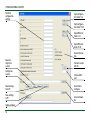
1
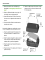
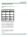
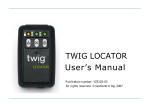
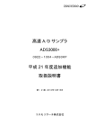
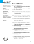
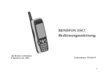
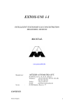
TWIG LOCATOR
User’s Manual
Publication number: YZ3103
All rights reserved. © Benefon Oyj, 2006
•
This tracking device is designed for use on the E-GSM900/ DCS 1800/ PCS 1900 MHZ Tri Band networks. You can use
the device in all countries where the GSM network operators have a roaming contract with your network operator.
•
The device also includes integrated high-performance 12-channel GPS receiver. The unique combination of GPS and
GSM equipment in this device enables features like tracking and location requests as well as emergency calls and
messages. In order to function properly, some of these features may require third-party services. BENEFON is not
responsible for such services, their existence, functionality or compatibility with BENEFON products.
•
Information in this User´s manual is subject to change without notice. BENEFON reserves the right to change or improve their products and to make changes in the content without obligation to notify any person or organization of
such changes or improvements. BENEFON is not responsible for any loss of data, income or any consequential
damage whatsoever caused.
•
Some of the features described in this guide may be optional and intended to be purchased separately. For details,
please contact your dealer.For more information, details and descriptions, including assortment of chargers and
accessories, please visit the web site: www.benefon.com.
•
BENEFON warrants its products to be free of defects in material or workmanship when leaving the factory. A warranty certificate with the date of purchase is enclosed in the delivery. For details, see the warranty certificate.
Hereby, Benefon Oyj declares that this tracking device, type TGP85EG, is in compliance with the essential requirements and other relevant provisions of Directive 1999/5/EC.
•
FCC warning statements: This device complies with part 15 of the FCC Rules. Operation is subject to following two
conditions: (1) This device may not cause harmful interference, and (2) this device must accept any interference
received, including interference that may cause undesired operation. Changes or modifications not expressly approved by the party responsible for compliance would void the user’s authority to operate the equipment.
•
ACCESSORIES AND BATTERIES: use only accessories and batteries accepted by the product manufacturer. Do not
use incompatibe accessories and batteries.
•
Benefon and Twig are registered trademarks of Benefon Oyj.
Manufacturer: Benefon Oyj,
P.O. Box 84, 24101 Salo, Finland
Web site: www.benefon.com
0413
Made in Finland.
Copyright © 2006 Benefon Oyj. All rights reserved.
2
Correct disposal of this product:
The tracking device should not be
disposed with household or other
commercial wastes. Remove the
battery from the phone and dispose it according to local battery recycling laws.
CONTENTS
CONTENTS
NMEA output . . . . . . . . . . . . . . . . . . . . . . . . . . . 11
Messaging . . . . . . . . . . . . . . . . . . . . . . . . . . . . . 12
TWIG LOCATOR . . . . . . . . . . . . . . . . . . . . . . . . . . . . 5
SENDING AND RECEIVING MESSAGES . . . . . . . . 12
GETTING STARTED. . . . . . . . . . . . . . . . . . . . . . . . . 5
VOICE CALLING . . . . . . . . . . . . . . . . . . . . . . . . . . . 12
Inserting SIM-card . . . . . . . . . . . . . . . . . . . . . . . 5
CONFIGURATING LOCATOR . . . . . . . . . . . . . . . . 13
Inserting battery and back cover . . . . . . . . . . . . 6
Installing software and drivers . . . . . . . . . . . . 13
REMOVING BATTERY AND BACK COVER . . . . . . . . 7
Connecting to computer . . . . . . . . . . . . . . . . . . 13
KEYS, LEDS AND OUTER PARTS. . . . . . . . . . . . . . 7
Configuration settings. . . . . . . . . . . . . . . . . . . . 13
Turning Twig Locator on and off . . . . . . . . . . . . 8
Status LEDs . . . . . . . . . . . . . . . . . . . . . . . . . . . . . 8
Charging the battery . . . . . . . . . . . . . . . . . . . . . . 9
TWIG LOCATOR FEATURES . . . . . . . . . . . . . . . . . 10
Stand-by mode. . . . . . . . . . . . . . . . . . . . . . . . . . 10
Positioning . . . . . . . . . . . . . . . . . . . . . . . . . . . . . 10
Tracking . . . . . . . . . . . . . . . . . . . . . . . . . . . . . . . 10
Anchor. . . . . . . . . . . . . . . . . . . . . . . . . . . . . . . . . 10
DEVICE INFORMATION . . . . . . . . . . . . . . . . . . . . . 13
SECURITY SETTINGS . . . . . . . . . . . . . . . . . . . . . . . 13
Config 1: PIN Code . . . . . . . . . . . . . . . . . . . . 15
Config 2: ID . . . . . . . . . . . . . . . . . . . . . . . . . . 15
Config 3: Security code . . . . . . . . . . . . . . . . . 15
ALARM SETTINGS . . . . . . . . . . . . . . . . . . . . . . . . . 15
Config 15: Max. allowed movement in
anchor mode . . . . . . . . . . . . . . . . . . . . . . . . . 16
Config 16: Battery alarm level . . . . . . . . . . . 16
GPS SETTINGS . . . . . . . . . . . . . . . . . . . . . . . . . . . . 16
Config 11: Max GPS search time . . . . . . . . . . 16
Alarm . . . . . . . . . . . . . . . . . . . . . . . . . . . . . . . . . 11
3
CONTENTS
Config 12: GPS update in basic mode . . . . . . 16
Config 13: GPS update in tracking mode . . . 16
Config 14: GPS update in anchor mode . . . . 17
MESSAGING SETTINGS. . . . . . . . . . . . . . . . . . . . . . 17
Config 6: SMSC number . . . . . . . . . . . . . . . . 17
Config 23-27: Destination numbers . . . . . . . 17
VOICE CALL SETTINGS . . . . . . . . . . . . . . . . . . . . . . 17
Config 8: Terminate voice call . . . . . . . . . . . 18
Config 9: Voice call auto answer . . . . . . . . . . 18
Config 17: !IND messages (YES/NO) . . . . . . . 18
Config 18: Mic Bbcgain . . . . . . . . . . . . . . . . . 19
Config 28-32: Voice call numbers . . . . . . . . . 19
WHITE LIST . . . . . . . . . . . . . . . . . . . . . . . . . . . . . . . 19
White L1-32: White list numbers . . . . . . . . . 19
Opening and saving settings. . . . . . . . . . . . . . . 20
Updating software . . . . . . . . . . . . . . . . . . . . . . . 20
ACCESSORIES AND BATTERIES . . . . . . . . . . . . . 21
4
TWIG LOCATOR
TWIG LOCATOR
Twig Locator is an auxiliary device for locating
and tracking different targets. Place Locator
on your desired target, e.g car, and you can
easily monitor its location.
Twig Locator can send you continuously
updated position messages. With these messages, you can easily track your Locator’s
movements. You can also create an anchor
that alarms you if your Locator is moved outside of your defined area.
GETTING STARTED
Inserting SIM-card
Longer front
side screws
Back cover
You can call and send messages to Locator for
its updated position at any time. Additionally,
by making a voice call, you can also listen to
what happens nearby the device.
SIMcard
Shorter
back side
screws
SIM-card holder
Twig Locator is a GSM-device with in-built
GPS-positioning and support for MPTP commands. It can be used with any corresponding
Benefon GPS-GSM phones and back-end
devices with support for MPTP commands.
Front cover
5
GETTING STARTED
1. Remove the back cover and battery as
described in removing battery and back cover on
page 7.
5. Fasten the back cover with screws. Longer
screws are for the front and shorter ones
for the back side.
2. Slide the SIM card holder to the right. Lift
the holder into an upright position.
Longer front side
screws
3. Insert SIM card into the hole. Check that
the cut corner is placed at the bottom left
corner.
4. Close the holder. Slide the holder back to
the left until it locks.
Back
cover
Inserting battery and back cover
1. Place the bottom tabs of the battery into
the small hollows at the bottom of the
device.
Battery
release
catch
2. Push the battery towards the device until it
locks into place. Ensure that the battery
release catch is positioned upwards.
Battery
3. Place the back cover towards the device,
bottom first.
4. Press the cover to the device until it locks in
place at the top.
6
Shorter back
side screws
Front cover
Bottom tabs of
the battery
KEYS, LEDS AND OUTER PARTS
Note that battery will reach its full capacity
only after two or three complete charges. For
more information, see charging the battery on
page 9.
REMOVING BATTERY AND BACK COVER
1. Remove the screws by using the screwdriver included in Twig Locator sales package.
2. Remove the back cover by lifting it off front
side first.
KEYS, LEDS AND OUTER PARTS
GSM LED
Status LED
GPS LED
Anchor
button
Emergency
button
Power on/
off button
3. Remove the battery by pressing the battery
release catch downwards and lifting the
battery off.
Bottom connector for
charger (round hole
on the left)
Bottom connector
for USB-cable
7
KEYS, LEDS AND OUTER PARTS
Turning Twig Locator on and off
LED
Indicator light
You can turn Twig Locator on by pressing the
power on/off button. As a sign of starting-up,
all three LED indicators turn on for a couple of
seconds. After that the status LED continues
blinking for about 20 seconds.
GSM LED
1 blink/sequence when having a network
GPS LED
1 blink/sequence, if the GPS
has a valid position fix that is
not older than 5 minutes.
To turn the device off, press the power on/off
button again.
GPS LED
Continuously off, if previous
position is older that 5 minutes and a new position fix is
not available.
Status LEDs
When Twig Locator is turned on, LED indicators express the status of the device the fol-
You can ask the battery status by pressing the
power on/off button. The status LED indicates
battery level the following way:
lowing way:
8
LED
Indicator light
Status LED
Off, when the device is in
standby-mode.
GSM LED
Continuously on, when data
call is on, or a SMS message
is being sent or received.
Blinks/sequence
Battery status
1
Low (0-20%)
2
Fairly low (21-40%)
3
Fairly full (41-60%)
4
Almost full (61-80%)
Continuously on
Battery full (81-100%)
KEYS, LEDS AND OUTER PARTS
When battery is low, Locator also sends battery alarm message to your defined destination numbers. For more information, see config
23-27: destination numbers on page 17.
Charging the battery
4. You can operate Locator during charging.
However, if the battery is totally empty, it
might take several minutes before the
device can be used. If you turn Locator on
while charging, the LEDs indicate events
related to the ongoing mode, instead of
showing the charging status.
1. Plug the charger cable into the bottom connector of the device (round hole on the lefthand side).
2. Plug the charger into the mains outlet.
3. Charging starts automatically. As a sign of
charging, all three LED indicators are turned
on for a couple of seconds. After that the
GSM LED blinks in sequences, 2 blinks in a
sequence at first and then 4 blinks in a
sequence. When the battery is fully
charged, the GSM LED stays constantly on
until the charger is disconnected. If there is
an interruption or failure in charging, the
status LED is turned off. Unplugging and
replugging the cable displays the status of
charging. If the battery is full, the status
LED blinks 4 times, after which it is turned
off.
9
TWIG LOCATOR FEATURES
TWIG LOCATOR FEATURES
mation. In the tracking mode, you can easily
monitor movements of e.g. your car.
Stand-by mode
Tracking is activated by sending Locator a
?TRG, ?TRC or ?TRS message from a mobile
phone or a back-end system supporting MPTP
protocol.
When Twig Locator is turned on, it enters into
stand-by mode. In the stand-by mode, the
device is not activated by any process but it is
ready to receive and answer location
requests. Stand-by mode is deactivated when
some other mode is activated.
Positioning
You can ask your Locator’s position by sending
it a ?LOC message. As a response, you will
receive a message including information on
your Locators position (coordinates), time,
speed and direction. For more information,
see sending and receiving messages on page 12.
Tracking
Tracking mode means that Locator is activated
to continuously send updated location infor-
10
If ?TRS or ?TRC is activated, tracking can be
cancelled by sending a ?STO message. If
?TRG is activated, tracking is cancelled by
sending a ?TRG_99_0 message.
Tracking mode can be activated simultaneously with anchor and alarm modes.
Anchor
Anchor mode can be used to anchor Twig
Locator to a defined position. In anchor mode,
Locator is continuously calculating its current
position and comparing it with the position it
had when the anchor mode was entered.
Anchor mode is switched to alarm mode, if the
distance between Locator and its original
position becomes more than allowed. You can
TWIG LOCATOR FEATURES
set the alarm triggering distance by defining
maximum allowed movements in configuration settings. For more information, see config
after one hour, or if another mode is activated
by a command.
15: max. allowed movement in anchor mode on
page 16.
NMEA output
To enter the anchor mode, press and hold
down anchor button for about 5 seconds. You
can deactivate the mode by pressing the
anchor button again. Anchor mode can be
activated simultaneously with tracking and
alarm modes.
Alarm
Alarm mode is activated, when the alarm button is pressed and held down for 3 seconds. If
there is an external alarm button connected,
it can also be used to activate the alarm
mode. In the anchor mode, the alarm is activated automatically when Twig Locator is
moved outside the defined area.
Twig
also
data
data
Locator can send position information
as NMEA strings. NMEA, a GPS-based
transferring standard, is used to transfer
from Locator to PC.
NMEA mode can be activated while in any
other mode: tracking mode, anchor mode or
alarm mode. Connect Locator to PC with mini
USB cable. Activate the NMEA mode by pressing and holding down the anchor and alarm
buttons simultaneously for 3 seconds. When
the mode is activated, the sending of NMEA
data is started.
If you want to leave the NMEA mode, press
and hold down the buttons again.
In the alarm mode, Locator is running at full
power and is ready to respond to your commands. The mode is automatically deactivated
11
TWIG LOCATOR FEATURES
Messaging
VOICE CALLING
SENDING AND RECEIVING MESSAGES
Voice calling enables you to listen to your
Locator. When a call starts, Locator’s microphone is activated and you can listen to what
happens within microphone’s reach e.g. other
person’s speak. Note that there is no speaker
in Locator, so transmitting voices to Locator is
not possible.
Position updates, tracking updates, anchor
and other alarms are transmitted as SMS
messages by Twig Locator. Sending tracking
updates and anchor alarms, is automatical
when the desired mode is on, and defined
conditions are fulfilled. Messages are sent to
phone numbers defined as your destination
numbers. See config 23-27: destination numbers on
page 17 for more information.
You can send an update request to your Locator by using your phone’s special applications,
e.g. Twig Navigation.
When a position update request is received,
Locator automatically checks if the sender’s
phone number can be found in White list.
If the sender’s phone number is stored in
White list, or if White list is empty, the phone
number is consired as valid, and position
update is sent as a reply. For more information about White list, see white list on page 19.
12
A voice call can be initiated by Locator or a
partner. If the call is initiated by Locator, the
available phone numbers are defined in voice
call numbers. See config 28-32: voice call
numbers on page 19 for more information.
If the call is coming from a partner, and automatic answer is set off, the call is automatically rejected. If the automatic answer is set
on, the phone number is automatically compared to the phone numbers stored in White
list. If the number is stored in the list, or if
White list is empty, the call is accepted. For
more information about defining automatic
answer and White list, see config 9: voice call
auto answer on page 18 and white list on page 19.
CONFIGURATING LOCATOR
CONFIGURATING LOCATOR
Installing software and drivers
There is an installation CD-ROM included in
your Twig Locator sales package. To configure
Twig Locator with your PC, you need to install
application software and USB-drivers from the
CD-ROM into your PC.
Connecting to computer
Once the software and drivers are installed,
you can establish a connection between Locator and your computer.
Note that Locator must be turned off when
connecting to computer except when the
NMEA mode is activated.
Connect Locator to your computer with Mini
USB cable. Then double-click Locator .exefile on your computer to open the configuration software.
Once the software is open, choose the right
COM-port from the COM drag-down menu and
press Connect. The connection between Locator and PC is established.
Configuration settings
Connect Locator to your computer as
described in connecting to computer on page 13.
You can edit and define several settings,
including security settings and available connections, to be used with your Locator.
DEVICE INFORMATION
The Info box displays details on your Locator ,
including the IMEI (International Mobile
Equipment Identity) code as well as software
version and GSM module numbers.
SECURITY SETTINGS
Locator’s SIM card can be protected by defining PIN and security code numbers. You can
also define an ID for your device.
13
CONFIGURATING LOCATOR
Fields for
configuration
settings
Open configuration fields 1-16
Open configuration fields 17-32
Open White list
fields 1-16
Open White list
fields 17-32
Device information
Read settings from
Locator
Configurate
Locator
Read settings
from PC
Save settings
to PC
Update software
14
Connect Locator
with PC
Choose COMport
Select file to
configure
Select software
file
CONFIGURATING LOCATOR
Config 1: PIN Code
Config 2: ID
PIN code (4 digits) is used to unlock your SIM
card, unless you are using a SIM card in which
the PIN code is disabled.
You can define an identification code for your
Locator. This code may contain both numbers
and letters, and it is case sensitive. Default
value for the ID code is: Locator_2.
Default value for PIN code is 9999. Replace the
value with your own PIN code, or leave the
field blank if the PIN code has been disabled.
If the PIN code is defined incorrectly, you
won’t be able to turn on your Locator. After
three failured attempts, the SIM card will be
blocked.
If your SIM card gets blocked, you need a PUK
code (8 digits) to open it. Remove the SIM
card for Locator and install it into a phone
compatible with your SIM card. When trying
to open the phone, it will prompt you for the
PUK code. After entering the PUK code, key in
a new PIN code. You can then install the SIM
card back to Locator.
Config 3: Security code
Security code is used when configurating
Locator and activating its different features.
The security code consists of 4 digits. Default
security code is 0000.
ALARM SETTINGS
Config 10: Auto leaving from alarm mode
Auto leaving from alarm mode defines time
after which Locator automatically leaves the
alarm mode. Valid values for this field are
between 00.30.00 (hh.mm.ss) and 23.59.59
(hh.mm.ss). Default value is 01.00.00 (one
hour).
If you fail to key in the correct PUK code 10
times in a row, your SIM card will be permanently blocked. If this happens, contact your network operator to get a new SIM card.
15
CONFIGURATING LOCATOR
Config 15: Max. allowed movement in anchor
mode
You can define a maximum distance that
Locator is allowed to move from the original
position in the anchor mode. Once the limit is
exceeded, a movement alarm is triggered.
Allowed distance can be set to: 0035... 9999
(meters). Default value is 0250 (meters).
Config 16: Battery alarm level
Locator can alert you when its battery level is
declined under certain level. You can define
the alarm level at 20, 40, or 60 percentage of
full battery charge. Default value for the
alarm is 20 percent. Note that value 00 means
that the alarm is deactivated.
GPS SETTINGS
You can define settings for GPS positioning in
different modes, as well as set time limit for
refreshing GPS position.
16
Config 11: Max GPS search time
You can define for how long GPS is trying to
get a refreshed position after receiving a position request. If the refreshed position is not
acquired within that time, Locator sends position update using the previously stored position. Valid values for GPS search time are
between: 00.00.00... 00.10.59 (hh.mm.ss).
Default value is 00.01.00 (one minute).
Config 12: GPS update in basic mode
You can define how frequently GPS is updating
position in the basic mode. Time interval can
be set to: 00.00.10... 00.59.59 (hh.mm.ss).
Default value is 00.05.00 (five minutes).
Config 13: GPS update in tracking mode
You can define time interval for GPS position
updates in the tracking mode. Valid values are
between: 00.00.10... 00.59.59 (hh.mm.ss).
Default value is 00.10.00 (ten minutes).
CONFIGURATING LOCATOR
Config 14: GPS update in anchor mode
You can define time interval for GPS position
updates in the anchor mode between:
00.00.10... 00.59.59 (hh.mm.ss). Default value
is 00.01.00 (one minute).
MESSAGING SETTINGS
You can define the SMS center number that is
used in SMS messaging, as well as destination
numbers to define where alarms and position
updates are sent by Locator. You can also
define, whether or not you wish to enable
!IND messages.
Config 6: SMSC number
The SMS center number is normally stored in
you SIM card from where Locator reads it
automatically.
If there is no SMS center number available in
the SIM card, the number stored in SMSC
number field is used instead. If both an SMS
center number in the SIM card and a stored
number in SMSC number field are available,
the number in the SIM card is used.
If you wish to define a number in the SMSC
number field, write the digits together without
blanks and special characters. If you wish to
use international phone numbers, write sign +
and the country code in front of the number.
Or use national phone numbers without + and
the country code.
Config 23-27: Destination numbers
You can define five destination numbers in the
fields 23: Alarm number 1.. 27: Alarm number 5.
Alarm messages, including battery alarm
messages, are sent to these numbers.
Write the phone numbers using international
code.
VOICE CALL SETTINGS
Voice calls can be initiated by Locator under
specific circumstances. You can define allowed
phone numbers for outgoing voice calls, as
well as settings for terminating and autoanswering voice calls.
17
CONFIGURATING LOCATOR
Config 8: Terminate voice call
Terminate voice call defines time limit for
voice calls. When the limit is reached, the
voice call will be automatically closed. Available values for the time limit are: 00.01.00...
00.59.00 (hh.mm.ss). Default value is 00.10.00
(ten minutes).
Config 9: Voice call auto answer
You can define whether or not you wish Locator to answer automatically to incoming voice
calls. Default value for this field is NO. If you
wish to set the automatic answer on, type
YES.
Answering voice calls depends on both the
automatic answer and White list settings:
• Automatic answer is off, there are no numbers stored in White list: Incoming call is
rejected and a location message (!LOC) is
sent to the caller.
• Automatic answer is off, there are numbers stored in White list: If the caller’s
phone number can be found in White list,
18
the call is answered. Otherwise the call is
rejected and a location message (!LOC) is
sent to the caller.
• Automatic answer is on, there are no numbers stored in White list: All incoming calls
will be answered.
• Automatic answer is on, there are some
numbers stored in White list: If the caller’s
number can be found in White list, the call is
answered. Otherwise the call is rejected
without sending a location message.
For more information about White list numbers, see white list on page 19.
Config 17: !IND messages (YES/NO)
You can define whether !IND messages can be
sent or not. A !IND message is sent when
anchor alarm is activated by pressing the
anchor button.
The default value for !IND messages is NO. If
you wish to enable sending !IND messages,
change the setting into YES.
CONFIGURATING LOCATOR
Config 18: Mic Bbcgain
You can define microphone volume level compared to the default volume level of Locator’s
GSM module. The field value can be set to 0-7,
in which each number represents an increase
of 6 decibels compared to the original GSM
module settings. There is no default value for
this field. If the field is empty, original GSM
module volume level is used.
Config 28-32: Voice call numbers
Available phone numbers for outgoing voice
calls can be defined in configuration fields 2832. Write the phone number digits together
without blanks and special characters. If you
want to use international phone numbers,
write the plus sign (+) and a country code in
front of the number. Or use national phone
numbers without the plus (+) and the country
code.
When a call is initiated, Locator starts calling
to the first defined phone number (Field 28).
If the call can be established to this number,
there will be no attempts to another numbers.
If the call cannot be established to the first
number, the second number is called instead.
The cycle will go on until three attempts to all
defined numbers.
Note that outgoing voice calls can be initiated
only if there is at least one voice call number
defined.
WHITE LIST
In the White list, you can restrict phone numbers from which voice calls and commands
can be received by your Locator.
White L1-32: White list numbers
You can define up to 32 White list numbers
which can be any valid phone numbers. When
there is at least one stored phone number, the
White list is activated. This means that
incoming voice calls and commands are
accepted only, if they are received from the
White list numbers. The authorization is done
by comparing the last 7 digits of the sender’s
phone number to the corresponding digits of
all your stored White list numbers.
19
CONFIGURATING LOCATOR
Write the phone number digits together without blanks and special characters. If you want
to use international phone numbers, write the
plus sign (+) in and a country code in front of
the number. Or use national phone numbers
without the plus sign (+) and the country
code.
Note that if there are no White list numbers
defined, incoming voice calls and commands
may be accepted from any sending device. For
more information on accepting incoming voice
calls, see config 9: voice call auto answer on
page 18.
Opening and saving settings
Before opening and saving configuration settings, make sure that the connection between
Twig Locator and the PC is established in a
way described in connecting to computer on
page 13.
To open existing configuration settings for
editing and saving, press the Select EE button
to search for your Twig Locator configuration
20
file. Then press Read EE to open the settings
which are currently saved in Locator. If you
wish to open the settings file stored on your
computer, press File Read EE. You can now edit
the settings as you wish.
You can configurate your Locator according to
your defined settings by pressing the Program
EE button. A progress bar displays the status
of the configuration update. If you want to
save the configuration settings to your PC,
press File Write EE.
Updating software
Updating software is done in the Firmware
field. Press Select FW to browse for the software update file. Update your existing Twig
Locator software by pressing Program FW. A
progress bar displays the status of the updating process.
ACCESSORIES AND BATTERIES
ACCESSORIES AND BATTERIES
Following accessories are available for this
product:
Accessory
Type
Order code
Mains charger
EU
CMA-80-230
YO3005
Mains charger
UK
CMA-80-230
YO3006
Plug-in charger
CCS-80-12
YO3010
Stardard battery
BBL-80N
YO3000
Mini USB Cable
YC3003
Note: use only accessories and batteries
approved for this device by the device manufacturer. The use of incompatible accessories and
batteries may cause undesired operation and
void the manufacturer’s warranty for the product.
Check the compatibility of new power supply
units and other accessories at the dealer or
manufacturer.
21