1
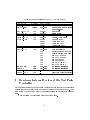
Compass Note 1999-9
CATCH1
A Test-facility for COMPASS Front-End Electronics
User Manual
Update for VME Block Transfer
G. Braun, H. Fischer, J. Franz, A. Grunemaier,
F.H. Heinsius, K. Konigsmann, M. Schierloh,
T. Schmidt, H. Schmitt, J. Urban
Fakultat fur Physik, Universitat Freiburg, 79104 Freiburg, Germany
June 30, 1999
1 Changes for addressing the CATCH1
The latest version of the CATCH1's VME interface can handle block transfer
requests to read front-end data from the FIFO-buer. As shown in the table
below the READ FIFO command's oset address changed to %8000 (was
%08). At this address the CATCH1 responds to both, single quad byte
transfers and block transfers. For the block transfer block sizes of up to 32
kByte are allowed.
Other changes concern the two commands REFRAME and BISTEN
which are no longer available and the modules base address. The two four bit
rotary switches now are compared to the adress lines A23-A16 (was A15-A08)
which results in a range for possible base addresses from
%E000 0000 to %E0FF 0000.
1
Table 1: Oset addresses of the CATCH1 commands
COMMAND
READ ID
READ FIFO
OFFSET DATA WORD
%00
D31-D00
CATCH1 identier
%8000 D31-D00
READ STATUS
READ FPGA
WRITE SERIAL
WRITE FPGA
WRITE TRIG
%10
%18
%40
%48
%50
PROG FIFO
PROG FPGA
%80
%88
REFRAME
BISTEN
%98
%90
RESET FIFO
RESET FPGA
%C0
%C8
three data words from
the front-end
D15-D07
D31-D16
D23-D00
D31-D16
D03=1
D02=1
D01=1
D00=1
D31-D16
D07-D00:
%01
%02
%04
%08
%10
%20
%40
%80
status bits
scaler values
setup data to front-end
pattern, pulse height
User command
Clear command
Reset command
Trigger command
set FIFO ags
data transferred:
enable programming pins
disable programming pins
set PROG pin to 0
set PROG pin to 1
set DIN pin to 1
set DIN pin to 0
set CCLK pin to 1
set CCLK pin to 0
-
reset FIFO buer
reset Test Pulse Controller
D07-D00
D07-D00
no longer available
no longer available
2 Erratum: Internal Scalers of the Test Pulse
Controller
In the actual design of the Test Pulse Control Unit the readout of the internal
scalers for the four User Commands and Pattern Strobe does not work. Thus
each attempt to read out one of the scalers results in obtaining a value of
zero.
A new revision of this design will be provided soon.
2