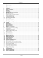
1
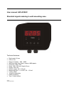
User manual AKV-2VR4C Standard signal metering in wall-mounting case Technical features: • • • • • • • • • • • • • Digit height: 20 mm Colour: red Range of display: -999…9999 Wall-mounting case: black, made of ABS-plastic Protection class: IP65 Sizes: 160 x 130 mm, Depth 60 mm Supply: 230 VAC Sensor supply: 24 V / 50 mA Measuring input: 0 -10 VDC, 0/4 – 20 mA 2 relay output 10 point linearisation Offset presetting Tara- / Hold-function V1.00 Stand 08-02-2010 Contents 1. 2. 2.1. 2.2. 2.3. 2.4. 3. 3.1. 3.2. 3.3. 4. 4.1. 4.2. 4.3. 4.3.1. 4.3.2. 4.4. 5. 5.1. 5.1.1. 5.1.2. 5.2. 5.3. 5.4. 5.5. 5.6. 5.6.1. 6. 6.1. 6.1.1. 6.2. 6.2.1. 6.2.2. 6.2.3. 7. 7.1.1. 7.1.2. 7.1.3. 7.1.4. 7.1.5. 7.1.6. 7.1.7. 7.1.8. 7.1.9. 7.1.10. 7.1.11. 7.1.12. 7.1.13. 8. 9. 10. 10.1. 10.2. Brief description ........................................................................................................................3 Safety advices ..........................................................................................................................3 Proper use ................................................................................................................................3 Control of the device.................................................................................................................3 Installation.................................................................................................................................3 Notes on installation .................................................................................................................3 Assembly ..................................................................................................................................4 Dimensions ...............................................................................................................................4 Assembly of the wall-type housing ...........................................................................................4 Mounting holes .........................................................................................................................5 Electrical connection.................................................................................................................5 Position of the connecting terminals .........................................................................................5 9-pole connector strip ...............................................................................................................6 5- pole connector strip ..............................................................................................................6 Input for standard signals .........................................................................................................6 Sensor supply ...........................................................................................................................6 Connection examples ...............................................................................................................7 Operation ..................................................................................................................................8 Operating and display elements ...............................................................................................8 Keys 8 Displays ....................................................................................................................................8 Switching on .............................................................................................................................9 Starting sequence.....................................................................................................................9 MIN/MAX-memory ....................................................................................................................9 Overflow and Underflow ...........................................................................................................9 Relay.......................................................................................................................................10 Optical response display flashing ...........................................................................................11 Programming ..........................................................................................................................12 Programming procedure .........................................................................................................12 Change to the operating mode ...............................................................................................13 Measuring input ......................................................................................................................13 Factory calibration ..................................................................................................................13 Sensor calibration ...................................................................................................................14 Sensor linearisation ................................................................................................................14 Device parameter ...................................................................................................................15 Measuring input PN0 ..............................................................................................................15 Skaling PN1 and PN2 .............................................................................................................15 Decimal point PN3 ..................................................................................................................15 Offset shift PN5.......................................................................................................................15 Zero point suppression PN10 .................................................................................................15 Indication time PN13...............................................................................................................15 Measuring time PN14 .............................................................................................................16 Security setting, user level PN50 to PN52..............................................................................16 Allocation of functions of the zero key PN54 ..........................................................................17 Display flashing PN59.............................................................................................................17 Switching points PN60 to PN75..............................................................................................17 Linearisation PN100 to PN110 ...............................................................................................17 Serial number PN200 .............................................................................................................17 Program number table ............................................................................................................18 Technical data ........................................................................................................................20 Trouble shooting .....................................................................................................................22 Questions and answers ..........................................................................................................22 Reset on default values ..........................................................................................................22 2/24 Brief description 1. Brief description With the digital indicator AKV-2VR4C standard signals DC 0/4 … 20 mA or DC 0 … 5/10 V can be measured. The 4-digit display shows the measurements or the scaled value of the measurement. During programming the display is used to indicate the set values and the user prompts. Two relays are available to monitor threshold values the status of which is displayed via two separate LED on the front. The integrated 24 VDC voltage output is used to supply possible sensors. 2. Safety advices Please read the users guide before installation and keep it for future reference. 2.1. Proper use The AKV-2VR4C is designed for the evaluation and display measuring transmitter signals. With the alarm outputs, it is possible to perform simple control tasks. Danger! Careless use or improper operation can result in personal injury and/or damage to the equipment. 2.2. Control of the device The indicators are checked before dispatch and sent out in perfect condition. Should there be any visible damage, we recommend close examination of the packaging. Please inform the supplier immediately of any damage. 2.3. Installation The AKV-2VR4C must be installed by a suitably qualified specialist (e.g. with a qualification in industrial electronics). 2.4. Notes on installation There must be no magnetic or electric fields in the vicinity of the device, e.g. due to transformers, mobile phones or electrostatic discharge. The fuse rating of the supply voltage should not exceed a value of 1A N.B. fuse. Do not install inductive consumers (relays, solenoid valves etc.) near the device and suppress any interference with the aid of RC spark extinguishing combinations or freewheeling diodes. Keep input, output and supply lines separate from one another and do not lay them parallel with each other. Position go and return lines next to one another. Where possible use twisted pair. Screen off and twist sensor lines. Do not lay current-carrying lines in the vicinity. Connect the screening on one side on a suitable potential equaliser. The device is not suitable for installation in areas where there is a risk of explosion (hazardous areas). Any electrical connection deviating from the connection diagram can endanger human life and/or can destroy the equipment. Do not install the device nearby a heat source (ambient temperature). 3/24 Electrical connection 3. Assembly The wall-type housing consists of an upper part and a lower part. A suitable seal has been inserted in the lower part to achieve protection IP66. In the upper part is the AKV-2VR4C with its operating and display elements. On the back are the terminals for all the electrical connections. The AKV-2VR4C is intended for wall mounting. 3.1. Dimensions 130 mm 160 mm Housing depth = 60 mm 3.2. Assembly of the wall-type housing I. Before mounting the unit, the side flaps covering the area, where the screws are located, must be flapped open to the left and right. II. With a suitable screw driver loosen the 4 fixing screws, joining the upper to the lower section. Now the upper part can be removed from the lower part. The upper section is connected to the lower section via a catch support, facilitating subsequent cable assembly on the AKV-2VR4C unit, which is hanging downwards. III. In the next step, in accordance with the above diagram, 4 holes should be drilled for the screws. After this you can mount the housing on the wall with the PG screws aligned upwards. IV. Now the connecting cables can be fed via the PG screws to the unit and connected to the screw clamp terminal in line with the connection diagram. V. After successfully mounting the lower section, lift up the upper section with the AKV2VR4C and place it on the lower section. Using the 4 fixing screws, screw the upper part to the lower part. Take care that the screws are completely tightened in order to attain protection IP66. Finally, fold the cover flaps inwards again. 4/24 Electrical connection 3.3. Mounting holes 160,0 ø5 ,2 ,2 ø5 ø5 ,2 130,0 74,0 ,2 ø5 139,0 Maßbild der Befestigungslöcher 4. Electrical connection Connect all the signals needed for operation to the back terminal strips. The connecting terminals are provided with a reference grid of 5.08 mm as clamp terminals. These enable the connection of wires up to 2.5 mm². 4.1. Position of the connecting terminals 5/24 Electrical connection 4.2. 9-pole connector strip Via the connector strip with the terminal numbers 6 to 14 the voltage supply/auxiliary power of the device and the two relay outputs are connected. Relay 1 (S1) 6 7 Normally Normally open closed 8 Com Auxiliary power 9 10 11 L PE N Relay 2 (S2) 12 13 Normally Normally open closed 14 Com 4.3. 5- pole connector strip Via the connector strip with the terminal numbers 1 to 5 the signal input for the standard signals and the sensor supply are connected. 4.3.1. Input for standard signals The input signal is connected to terminals 3 to 5. The AK-M2-VVR4C has a voltage input and a current input to which most conventional sensors with a standard signal output can be connected. The input is galvanic isolated from the power supply (auxiliary voltage) and the sensor supply. Sensor 0...10 V 0...5 V 0...20 mA 4…20 mA Measuring range -12 V…+12 V 12 -24 mA…+24 mA I+ 11 U+ 10 UI- Examples for connecting different transmitters can be found in the section on connecting examples. 4.3.2. Sensor supply The 24 VDC sensor supply is available at terminals 1 and 2. The sensor supply is galvanic insulated from the measuring input. Current loop sensors (2-wire) and 3-wire and 4-wire sensors can be operated via the sensor supply as long as their current consumption is not higher than 50 mA (Power consumption < 1.2 VA). 1 Sensor supply + 2 Sensor supply - 6/24 Operation 4.4. Connection examples This section gives a few examples of practical connections. Other connection options can be combined from the various examples. Measuring a current signal (4-20 mA) from a 2-wire transmitter, using the sensor supply. Measurement of a voltage signal (0-5 V or 0-10 V) from a 3-wire transmitter using the sensor supply 24 VDC. The ground is bridged via the sensor, which eliminates the measuring error through the drop in voltage on the sensor supply wires Measuring a current signal (0 … 20 mA) from a 3-wire transmitter using the sensor supply 24 VDC. The voltage drop on the sensor supply wire is irrelevant, which is why this can also be bridged directly on the indicator. 7/24 Operation 5. Operation This unit is operated via the [P], [S] and [T] keys. 5.1. Operating and display elements 7 5 1/min S1 S2 6 1 2 3 4 5 6 7 Program key [P] Minus key [DOWN] Plus key [UP] Option key Set point display 1-2 Dimension gap 7-segment display P 1 2 3 4 Front view 5.1.1. Keys The AKV-2VR4C has 3 keys, with which you can parameterise and call up various functions during operation. 1 Program key [P] 2 Minus key [▼] 3 Plus key [▲] With the program key, you can call up the programming mode or perform various functions in the programming mode. With the minus key, you can call up the MIN memory or alter parameters in the programming mode With the plus key, you can call up the MAX memory or alter parameters in the programming mode. 5.1.2. Displays The AKV-2VR4C has a 4-digit 7-segment display and two LED. 4 7-segment display 5 Setpoint display In the 7-segment display measuring values are displayed, respectively. during programming the program numbers or parameter are displayed. In the setpoint display the state of the relay outputs is displayed. If a relay is switched, the LED lights up. 8/24 Operation 5.2. Switching on Before switching on you have to check all the electrical connections to make sure they are correct. On completion of the installation, the device can be switched on by applying the power supply. 5.3. Starting sequence During the switching-on process a segment test is performed for approx. 1 second, whereby all LEDs on the front (including alarm LEDs) are triggered. After this, the type of software is indicated for approx. 1 second and then, also for 1 second, the software version. After the starting procedure, the unit changes to operation/display mode. 5.4. MIN/MAX-memory The measured minimum and maximum values are saved in a volatile memory in the unit and get lost when the unit is switched off. You can call up the contents of the memory by pushing (less than 1 second) the [S] or [T] key. The relevant value is indicated for approx. 7 seconds. By briefly pressing the same key again, you will return immediately to the display mode. [▲] [▼] ⇒ ⇒ Display of the MAX value Display of the MIN value You can erase the value shown in the display by simultaneously operating the [▲] & [▼] keys. The erasure is acknowledged by horizontal bars. The content of the memory is lost when the unit is switched off. 5.5. Overflow and Underflow An overflow of the display is indicated by horizontal bars at the top of the 7-segment display „ ¯ ¯ ¯ ¯ “. An underflow of the display is indicated by horizontal bars at the bottom of the 7-segment display „ _ _ _ _ “. 9/24 Operation 5.6. Relay With the aid of the LED below the 7-segment display, you can view the switching state of the relay. An active relay is indicated by the relevant LED lighting up. The relays have the following properties with regard to their switching properties: Switch-off delay Deactivated, activated Threshold value for switchover Width of the window between the switch thresholds active above SP value / active below SP value Time between reaching the threshold and the resultant switching on of the relay Time between reaching the threshold and the resultant switching off of the relay treshold Setpoint output Threshold Hysteresis Operating principle Switch-on delay setpoint raised ON fallen Active above SP value The setpoint is off below the threshold and switched on on reaching the threshold. OFF display treshold hysteresis setpoint Switch-on delay The relay is on e.g. 10 seconds after reaching the threshold; briefly exceeding the threshold does not lead to the relay being switched on. The switch-off delay functions in a similar manner, in other words it keeps the alarm output switched on until the parameterised time has elapsed. ON fallen raised Active below SP value The setpoint is on below the threshold and switched off on reaching the threshold. OFF display hysteresis input 10 treshold 0 5 relay switch on delay 10 s time [s] 5 time [s] ON OFF 10/24 Operation 5.6.1. Optical response display flashing The switching on of one or more alarm outputs can also be set to trigger a flashing of the display to enhance the optical response. 11/24 Programming 6. Programming The display shows the program numbers (PN) right-aligned, as a 3-digit number with a “P” at the front. Display of e.g. program number 0 6.1. Programming procedure The entire programming of the AKV-2VR4C is done by the steps described below. Change to the programming mode Pushing the [P] key changes to programming mode. The unit goes to the lowest available program number. When the programming lock is activated, the key must be pressed for at least 1 seconds. Example: Change to programming mode by pushing key [P]. The first released program number (PN) appears, in this case PN0. P Changing to other program numbers To change between individual program numbers, hold the [P] key down and press the [S] key for changing to a higher program number or the [T] key for changing to a lower number. By keeping the keys pushed, e.g. [P] & [S], the display will begin, after approx. 1 second, to automatically run through the program numbers. P Example: A 1 is parameterised under PN0 Hold the [P] key down and press the [S] key once. PN1 appears in the display. Under this parameter, the final value of input can be changed. Change to the parameter Once the program number appears in the display, you can press the [T] or [S] key to get to the parameters set for this program number. The currently stored parameters are displayed. Example: By pressing the [T] or [S] key, the currently stored value for PN1 appears in the display. In this case, it is 75.64. P Changing a parameter After changing to the parameter, the lowest digit of the respective parameter flashes on the display. The value can be changed with the [S] or [T] key. To move to the next digit, the 12/24 Programming [P] key must be briefly pressed. Once the highest digit has been set and confirmed with [P], the lowest digit will begin to flash again. Example: The 4 is flashing; this is the lowest value digit and, by flashing, it is asking for a figure to be entered. In our example, the value is to be changed from 75.64 to P 75.00. You can change the value by changing the figure from 4 to 0 using the [S] or [T] key. To move to the next digit, the [P] key must be briefly pressed. The 6 begins flashing. Change the value from 6 to 0 using the [S] or [T] key. The 5 and the 7 need no change. Saving parameters All parameters must be acknowledged by the user by pressing the [P] key for one second. The changed parameters are then taken over as the current operating parameters and saved in the EEPROM. This is confirmed by horizontal bars lighting up in the display. Example: Save the parameters by pressing [P] for one second. P All the newly entered data are confirmed by the unit. If no confirmation is received, the relevant parameters have not been saved. Example: You receive confirmation from the unit that the changes have been saved through the appearance of horizontal bars in the middle segments. P 6.1.1. Change to the operating mode If no key is pressed in programming mode for approx. 7 seconds, the unit automatically returns to operating mode. 6.2. Measuring input The AKV-2VR4C is equipped with a measuring input for standard signals that enables standardised signals (e.g. 4 … 20 mA) from all kinds of different measuring transmitters on the market to be measured directly. 6.2.1. Factory calibration For this, various sensor values for 0 … 10 V, 0 … 5 V, 0 … 20 mA and 4 … 20 mA are stored in the unit and can be called up via the parameter PN0. They are called factory calibrations because the data were established during production and are saved 13/24 Programming permanently in the unit. It means that a pre-adjusted transmitter can be operated directly with the indicator without any need to previously connect the signal to be measured to the indicator. The indicator can be scaled freely according to the physical dimension to be measured. 6.2.2. Sensor calibration If, on the other hand, the sensor has not been pre-calibrated, the indicator can be adjusted and calibrated direct via the measurement together with the sensor path. This can be selected via the parameter PN0 = 0 and is consequently called sensor calibration. 6.2.3. Sensor linearisation In addition, non-linear sensors can be linearised with the aid of a characteristic line that can be saved in the indicator. This is described with the following example: The sensor signal must be parameterised in a strictly monotonously manner, i.e. every new calibration point (e.g. PN104) must have a higher input signal than the previous one (e.g. PN103) so that it is taken over by the indicator. Otherwise, no confirmation will be shown. On the other hand, the relevant indication values do not need to increase constantly. They can also fall or alternate between rising and falling. Example: To program e.g. 5 additional calibration points, 5 must be entered under PN100. Subsequently, for each of the calibration points, the voltage/current must be applied to the unit and the respective indication value programmed under the following program numbers PN101 – PN105. Linearisation of a pressure transmitter (0 ... 100 mbar) with output 0 … 20 mA. The indicated value before correction can be either calculated from the known characteristic line of the transmitter or determined empirically. The non-linear range is between 0 ... 75 mbar. For calibration point 101, this means: A pressure of 15 mbar, the transmitter delivers 3.3 mbar instead of the ideal value of 3.0 mbar. Since 20 mA in the display corresponds to 100.0 mbar, 3.3 mA in the display corresponds to 16.5 mA before the correction. Setpoint Pressure Output (PN) [mbar] transmitter [mA] 2 101 102 103 104 105 1 0 15 30 40 60 75 100 0.5 3.3 6.2 9.2 11.4 14.7 20.0 Indication before correction (IN) 2.5 16.5 31.0 46.0 57.0 73.5 100.0 14/24 Desired indication (OUT) 0.0 15.0 30.0 40.0 60.0 75.0 100.0 Programming 7. Device parameter The AKV-2VR4C has a number of unit parameters with which the function of the indicator can be adjusted to the relevant measuring tasks. Because of the large number of these settings and the limited possibility of displaying them on the 7-segment display, the parameters have been given consecutive numbers. 7.1.1. Measuring input PN0 One of the aspects in the basic configuration is the desired measuring input, which consists of the terminal selection and the relevant factory or sensor calibration. 7.1.2. Skaling PN1 and PN2 The two program numbers 1 and 2 are used to scale the indication. With these two parameters the end value and start value are parameterised. If sensor calibration has been selected via PN0 = 0, then the current for the relevant sensor signal must be applied during programming. Otherwise, a simple allocation of the selected input configuration will be made. For example, at PN0 = 3, which corresponds to a standard signal input 0…10 V, the value saved under PN1 will be indicated at 10 V, and the value saved under PN2 will be indicated at 0 V. 7.1.3. Decimal point PN3 By changing this parameter the number of places shown after the decimal point in the display is changed. This parameter has no influence on the scaling of the indication value, only on the position of the decimal point in the display. 7.1.4. Offset shift PN5 With this parameter it is possible to carry out a parallel shift of the parameterised characteristic line. This may be necessary, if for example a pressure transmitter ages over the course of time, giving rise to a shift in the zero point. With the parallel shift the transmitter can be adjusted back to the zero point. Another application is to parameterise a certain tank level to zero and have any deviation from this level displayed. 7.1.5. Zero point suppression PN10 Via the zero point suppression, an indication value window can be defined as zero. This means, for example, that at PN10 = 10, all indication values between –10 … 10 are shown in the display as zero. This function is intended to produce a reliable zero indication at high display resolution and low sensor accuracy around zero. This could be, for example, the rpm of an engine for which a zero would be expected in the display when standing still. 7.1.6. Indication time PN13 The indication time is the interval at which the display is updated. The longer the time between two indication cycles, the calmer the display. As a rule, the eye perceives the indication time of 1 s as very pleasant. If the adjusted indication time is longer than the adjusted measuring time, no averaging of the detected measuring values during the indication time takes place. The display will be always refreshed with the newest detected measuring value. 15/24 Programming 7.1.7. Measuring time PN14 The measuring time corresponds to the conversion time of the A/D conversion, which determines the response time of the alarm outputs. The longer the conversion time, the smaller the influence of disturbances and the higher the resolution of the measured signal. 7.1.8. Security setting, user level PN50 to PN52 With the parameters in the security settings, access to the program numbers is regulated through the setting of various user levels. The user levels divide the access into various levels. The user is only given access to the settings authorised by the system operator, such as the setting of thresholds. The lower the figure for the user level given under PN52, the lower the level of security of the unit parameters against user intervention. Userlevel (PN 52 =) Access to:: Locking code / user level Measuring input parameters Tara / Hold Linearisation parameters for measuring input Parameters of the alarm outputs Hysteresis of the alarm outputs Thresholds of the alarm outputs Access code Serial number 0 1 2 3 4 5 6 7 8 PN: 51, 52 0 ... 18 54 100 ... 110 59, 60, 63 … 65, 70, 73 … 75 62, 72 61, 71 50 200 X X X X X X X X X X X X X X X X X X X X X X X X X X X X X X X X X X X X X X X X X X X X X X The user levels 1 and 3 are reserved user levels at which access to the higher numbered user level is active. The parameterised user level PN52 is active as long as the locking code PN51 and the access code PN50 are different. On delivery of the AKV-2VR4C both parameters are set to 0000, so that the programming lock is deactivated. On changing to programming mode, the unit jumps to the first authorised program number. If user level PN52 = 3, then, for example, the parameters of the alarm outputs can be changed, but changing the parameter of the measuring input (PN0) is not possible at this user level. In order to obtain access to all program numbers later (equivalent to user level 0), you have to enter under PN50 the same code you entered before under PN51. You must then acknowledge this by pressing the [P] key for approx. 1 s. After this you have access to all program numbers. Caution! If the locking code becomes lost, the unit can be set to the default value 0000 at the manufacturer's without any data loss. 16/24 Programming 7.1.9. Allocation of functions of the zero key PN54 By pushing of the zero key functions like e.g. TARA and HOLD can be actuated or a offset shift can be preset. By allocation of TARA the key needs to be pushed for at least 1 second. The device confirms the function by showing „0000“ in the display. With activated offset shift, the value in PN5 will be added to the initial value directly by pushing the key. A display hold can only be actuated for approx. 20 seconds. By pushing the zero key again one turns back into the current measurement directly. During HOLD phase the display flashes. 7.1.10. Display flashing PN59 By activating the display flashing, various alarm states can be optically reinforced. The trigger for the display flashing can be freely assigned to the setpoint outputs. 7.1.11. Switching points PN60 to PN75 The behaviour of the switching points can be influenced via various program numbers. The data refer to the scaled measurement and are updated with the set measuring time. A description of the various parameters is given in Section 5.6 Relay. 7.1.12. Linearisation PN100 to PN110 Through linearisation, the user has the possibility to linearise a non-linear sensor signal. A detailed description can be found in the chapter on Sensor linearisation. Under PN100, the desired number of additional set points can be released. Only after changing the number are they accessible via the configuration PN101 to max. PN110. If PN100 = 0, then no PN101 will be displayed. To monitor the desired linearisation, all the set points should first be parameterised, otherwise there may be deviations from the desired value in the display! 7.1.13. Serial number PN200 Under PN200 the 4-digit serial number can be called up that allows allocation to the production process and the manufacturing procedure. This parameter can only be viewed. 17/24 Program number table 8. Program number table The program table lists all the program numbers (PN) with their function, range of values, default values and user level. PN Function 0 Channel 1 Measuring input Parameters 1 to 4 make use of the factory calibration. 1 2 3 Final value respectively fullscale Zero point respectively offset Number of decimal places 5 10 Offset shift on display value Zero point suppression General settings Display time Measuring time Security settings Programming lock Access code User level Threshold behaviour of LED display Actuator via zero key 13 14 50 51 52 54 59 Display flashing (approx. 0.5 seconds) No flashing Flashes at setpoint 1 Flashes at setpoint 2 Flashes at setpoint 1 and 2 60 Setpoint 1 Setpoint 1 61 62 63 Threshold Hysterisis Active below / above threshold value 64 Switch delay in seconds Range of value Default User level Current, Voltage 0 = Sensor calibration 1 = 0...20 mA 2 = 4...20 mA 3 = 0...10 V 4 = 0....5 V 2 2 -999...9999 -999...9999 0=0 1 = 0.0 2 = 0.00 3 = 0.000 -999…9999 0…999 1000 0 0 2 2 2 0 0 2 2 0.1 ... 10.0 0.01 ... 10.0 1.0 1.0 2 2 0000...9999 0000...9999 1...8 0000 0000 8 8 0 0 0 = deactivated 1 = TARA 2 = Offset shift 3 = HOLD 0 2 1 4 1000 1 1 6 5 4 1 4 0 no flashing 1 flashes at 1 2 flashes at 2 3 flashes at 1 and 2 0 = deactivated 1 = activated -999...9999 1...9999 0 = active below 1 = active above 0…1000 seconds 18/24 Program number table PN Function Range of value 65 Delay type 0 = none 1 = switch-on delay 2 = switch-off delay 3 = switch-on/-off delay 70 Setpoint 2 Setpoint 2 71 72 73 Threshold Hysterisis Active below / above threshold value 74 75 Switch delay in seconds Delay type Linearisation 100 Number of additional setpoints 101 Setpoints 1...30 ... 130 Information 200 Serial number Default 0 User level 4 1 4 1000 1 1 6 5 4 1 0 4 4 0...10 -999...9999 0 2 2 0...9999 0 8 0 = deactivated 1 = activated -999...9999 1...9999 0 = active below 1 = active above 0…1000 seconds 0 = none 1 = switch-on delay 2 = switch-off delay 3 = switch-on/-off delay 19/24 Technical data 9. Technical data Housing Dimensions Weight Fixing Material Colour Protection class Connection Display Digit height Segment colour Range of display Setpoints Overflow Underflow Display time Input Measuring range / Input resistance/ Measuring error (at measuring time =1 second) Temperature drift Measuring time = Display time Measuring principle Resolution (at 1 sec measuring time) Output Relay Switching cycles Sensor supply (galvanic insulated) Power pack Supply voltage (galvanic insulated) 160 x 130 x 60 mm (B x H x T) max. 430 g 4 fixing holes in the lower section of the housing ABS (UL94V-0) Black, RAL7035 Standard IP65 abatable screw terminals; line cross section up to 2.5 mm2 wire feed via PG9 screws 20 mm red -999...9999 one LED per switching point horizontal bars at top horizontal bars at the bottom 0.1 to 10.0 seconds Measuring range 0...10 V 0...5 V 0...20 mA 4…20 mA RI approx. 150 kΩ 150 kΩ 100 Ω 100 Ω Measuring error [%] MR 0,1 0,1 0,1 0,1 Digit ±1 ±1 ±1 ±1 all measuring inputs 50 ppm/K 0.1 to 10.0 seconds Voltage-/Frequency converter approx. 20 bit Switch-over contact 230 VAC 5 A respectively 30 VDC 2 A (cos ϕ = 1); with ohm resistive load 0,5 * 105 at max. contact rating 5 * 106 mechanically Separation as per DIN EN 50178 Characteristics as per DIN EN 60255 24 VDC; 50 mA 230 VAC / 50/60 Hz / ±10 % 20/24 Technical data Power consumption Memory Data life max. 8 VA Parameter memory EEPROM >20 years Ambient conditions Working temperature Storing temperature Climatic density 0...60 °C -20...80 °C rel. humidity ≤ 75 % on years average without dew EMV CE-sign DIN 61326 Conformity to 89/336/EWG Safety standard DIN 61010 21/24 Trouble shooting 10. Trouble shooting The following list gives the recommended procedure for dealing with faults and locating their possible cause. 10.1. Questions and answers I. The unit permanently indicates overflow „ ¯ ¯ ¯ ¯ “. ¾ The input has a very high measurement, check the measuring circuit. II. The unit permanently indicates underflow „ _ _ _ _ “. ¾ The input has a very low measurement, check the measuring circuit. III. The device shows “HELP” in the 7-segment display. ¾ The unit has found an error in the configuration memory. Perform a reset on the default values and reconfigure the unit according to your application. IV. Program numbers for parameterising the input are not available. ¾ The program lock is set to a user level that does not permit access. V. „Err1“ lights up in the 7-segment display ¾ This error can only be eliminated by the manufacturer. 10.2. Reset on default values To return the unit to a defined basic state, a reset can be carried out to the default values. The following procedure should be used: I. Switch off the power supply II. Press button [P] III. Switch on the power supply and press [P] for further approx. 2 seconds. With reset, the default values of the program table are loaded and used for subsequent operation. This puts the unit back to the state in which it was supplied. Caution! This is only possible when the programming lock PN50 allows access to all PNs or “HELP” is shown in the display. Caution! All application-related data are lost. 22/24 Trouble shooting 23/24 Trouble shooting 24/24