1
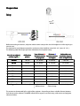
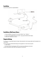
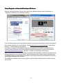
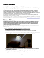
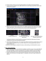
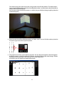
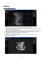
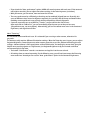
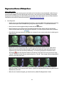
DAVID SLS-1
Getting Started
Guide
Version 3.4
DAVID Vision Systems GmbH
Rudolf-Diesel-Str. 2a
D-56070 Koblenz
Germany
Phone: +49(0)261 983 497-70
Fax: +49(0)261 983 497-77
Mail: [email protected]
Web: www.david-laserscanner.com
© 2012 DAVID Vision Systems GmbH
DAVID SLS-1
Contents of Package
• SL Scanner pre-mounted, consisting of
• Video projector
• Camera with focusable lens
• Mounting rack with ball joint (for camera)
• Tripod with protective bag
• 2 calibration panels with 2 mounting tracks 90°
• USB drive with DAVID-Laserscanner Pro Edition and camera drivers
• Accessories for projector
• External wall power supply
• Remote control
• VGA cable
• HDMI cable
• 2 AV cables (not required for scanner)
• Protective bag
• User Manual
• Adapter set for global power supply
• USB cable for camera
• Cable straps
System Requirements
• Windows XP, Vista or 7 (32-bit or 64-bit)
• 3D graphics adapter
• Available VGA or HDMI port
• Two available USB ports
• Recommended: Dual-core processor, 2 GHz, 4 GB RAM, NVIDIA or AMD graphics adapter
Safety Instructions
• Only operate the scanner in a dry environment.
• Do not operate the scanner in areas where there is a risk of explosion.
• Repairs to the scanner or its components may only be performed by an authorized service centre or the
DAVID-Laserscanner after-sales service.
• Do not make changes of any kind to your scanner.
3
Preparation
object size s
Setup
Before connecting the devices, adapt the whole scanner setup to the size of the object or surface region you
want to scan.
The intersection angle between projection and camera view should be around 20°-25° (max. 15°-35°).
The following table should give you some indications for an optimal setup:
Size of scan object /
surface region s
Calibration
pattern
Lens distance b
Distance d
between camera between scanner
and projector
and object
Achievable scan
resolution (approx.
0.2% of object size)
<30 mm
30 mm
ca. 30 mm
ca. 90 mm
< 0.1 mm
50 mm
60 mm
ca. 40 mm
ca. 120 mm
ca. 0.1 mm
70 mm
60 mm
ca. 65 mm
ca. 180 mm
ca. 0.15 mm
90 mm
120 mm
ca. 80 mm
ca. 220 mm
ca. 0.2 mm
120 mm
120 mm
ca. 110 mm
ca. 300 mm
ca. 0.25 mm
150 mm
120 mm
ca. 125 mm
ca. 350 mm
ca. 0.3 mm
200 mm
240 mm
ca. 160 mm
ca. 450 mm
ca. 0.4 mm
300 mm
240 mm
ca. 250 mm
ca. 700 mm
ca. 0.6 mm
500 mm
240 mm
ca. 400 mm
ca. 1200 mm
ca. 1.0 mm
in general
similar to object
angle 20°-25°
between them
object should fill
camera image
ca. 0.2% of object size
The camera can be mounted left or right of the projector – depending on how a suitable distance between
their lenses can be achieved. The DAVID software also supports a vertical setup, with camera and projector
above each other.
4
Installation
Connect all components as depicted below:
USB
VGA / HDMI
Installation of the Camera Drivers
1. Plug the USB drive into your PC, then choose “Open” resp. “Explorer”.
2. Launch “Install_DAVID-CCD-Camera_Driver“ (may require administrator rights).
3. Follow the instructions on screen.
Projector Settings
The projector is shipped with optimal settings. We recommend not to change anything in the projector's onscreen menu.
You can restore the recommended settings in the projector's on-screen menu any time:
1. Select “Reset“
2. Be sure to switch “Auto Keystone“ OFF, and set the manual Keystone value to 0.
For more information, please refer to the projector's User Manual.
5
Setup Projector as Extended Desktop in Windows
With your right mouse button, click on a free space on your Windows desktop. Choose “Resolution” or
“Properties” (depending on your Windows version).
In this dialogue window, you can separately change the settings of your two displays, monitor and projector.
Your monitor should be set as “main display”. Set the projector to be an extended desktop (“extend these
displays” / “extend desktop to this display”).
This setting is required so that DAVID can project its scan patterns and show the user interface on your
computer screen at the same time. You can find more detailed instructions in our online user manual at
http://www.david-laserscanner.com/ , “Manual”, in chapter “3D Structured Light Scanning“.
When these settings are correct, your monitor and projector will show different contents (but with the same
desktop wallpaper). You can move the mouse pointer sideways from the monitor into the projected image.
The Windows Taskbar and most desktop icons will be shown only on the monitor. All windows can be moved
from monitor to projector, and vice versa.
If the DAVID main window is shown on your projector, grab its title bar with the mouse and move it over to
your monitor.
6
Scanning with DAVID
Launch DAVID by starting “Start_DAVID3“ on your DAVID USB key.
On the left side you can see the expandable main menus. Each menu is dedicated to one of the following work
steps, which you will usually walk through from top to bottom.
For the individual work steps, different camera and/or projector settings may be optimal. For example,
Camera Calibration may require a different Exposure Time, or Texturing may require a darker projector
setting. The respective controls are available at all times, and DAVID will remember and restore the settings
separately for each work step – depending on which menu is currently expanded.
Our software is developed and improved continuously. Therefore, please use the automatic update. All
updates within versions 3.x are free of charge.
This printed manual refers to version 3.4 of the software and may already be out of date. Please also read our
detailed and always up-to-date online manual, which you can find on http://www.david-laserscanner.com/.
Calibration of the Scanner
One advantage of the SLS-1's modular setup is that its size can be adjusted to very different object sizes.
Therefore, calibration (measurement of the current hardware setup in the DAVID software) is required,
allowing the software to obtain undistorted 3D data at the correct scale. We use a calibration corner as
reference, whose properties are known precisely.
The three steps, hardware setup, camera calibration and projector calibration, must be carried out in the
following order.
1. Menu “Hardware Setup“: Adjustment and settings of projector and camera
1. Select setup type “Structured Light Setup“.
2. Choose the correct “Screen ID“ such that the stripe pattern is projected by the projector.
3. Place the scanner in front of the scanned object and adjust the projector's position and direction so
that its projection illuminates the scanned surface – not less, but also not much more.
4. Use the projector's focus ring to adjust sharpness, such that the black and white stripes are well
focused on the object surface.
5. Below “Camera”, select your camera (DAVID-CAM-2-M). You will see the live view. If necessary,
roughly adjust the camera's mechanic aperture and focus ring.
7
6. Aim the camera so that it can see the projected pattern on the object. Then fix the ball joint.
7. The Exposure Time should be set to 1/60s, otherwise the camera image might flicker or pulse when
looking at the projection.
8. Adjust the mechanic aperture at the camera's lens. Regard only those image regions that show the
circular wave pattern: The red intensity curves must be sinusoidal and must not be over- or undersaturated. In other words, the red sine curve must not be cut off at the blue borders.
Too dark.
→ Increase aperture size
Perfectly adjusted,
sine wave nearly reaches the
blue borders.
Too bright,
Sine wave is cut off (overdriven).
→ Decrease aperture size
The Projector Brightness control should be at maximum in most cases. Only reduce it if a clean,
undistorted sine wave cannot be obtained otherwise.
9. Look at the projected grey planes in the camera image. Adjust camera focus (mechanic focus ring) so
that the object is depicted as sharp as possible. Also you can use the projected black and white
stripes for focussing.
10. Fasten all screws (projector, ball joint of camera) so that nothing can be dislocated from now on.
2. Menu “Camera Calibration“
1. Select a calibration pattern size which fits to the object (see table on page 3). Set up the calibration
corner at precisely 90°, using the mounting tracks. For starters, the pattern should be flapped to
the inside, while advanced users may be able to reduce reflections with a concave corner setup.
2. Remove the object and set up the scanner and the calibration corner in front of each other, with
approx. the same distance as the object before. The projection and camera image should be well
focused.
8
The camera image must show at least the 6 ring markers and a few dot markers. The whole camera
image should be filled with around 15 to 70 calibration markers, and the camera should not able to
look past the calibration boards.
You can move, rotate and tilt the scanner as a whole, but you should not change anything above the
red mounting rack.
3. Enter the scale size of the calibration pattern at “Calibr. Scale”. You can find the number printed on
the panels right next to the respective pattern.
4. The projector now shows a plane white or grey face. You can adjust its brightness wit the Projector
Brightness control, so that the calibration markers are clearly visible in the camera image. If there
is enough environment light in the room, you can set the control to 0.
If necessary, you can adjust the camera Exposure too.
9
5. Click “Calibrate“ in order to calibrate the camera.
In this step the software computes the position and orientation of the camera, as well as the focal
length and distortion parameters of its lens.
6. From this moment on, do not move or adjust anything at the scanner – otherwise you will have to
repeat the calibration.
3. Menu “Structured Light Scanning“: Calibration of the projector
1. When you open the Structured Light Scanning menu, the projector will again show the setup
pattern, and both projector and camera will be set back to the settings you have made in step 1.
2. Select a profile (recommended: “default“).
3. Check the camera image again. In those areas that show the circular wave pattern, the red intensity
curves must not be cut off at the blue borders. Carefully adjust the lens aperture if necessary, but be
sure not to change the focus.
4. Click “Calibrate” in order to calibrate the projector.
In this step the software measures the position and orientation of the projector, its focal length and
distortion coefficients, as well as optical transmission properties and delays of the whole system.
Your scanner is now calibrated. This refers to the position and orientation of camera and projector relative to
each other, and the focus and brightness settings. You may move, rotate and tilt the scanner as a whole, and
you can close and restart the DAVID software, without losing the calibration.
However, if you rotate camera or projector with respect to each other or change the focus (e.g. in order to
scan much smaller or larger objects), you will have to repeat the whole calibration procedure.
10
3D Scanning
Menu “Structured Light Scanning“
• Place scanner and object in front of each other, like you did during calibration.
If the distance is too different, the projected stripes and camera image will be out of focus. In this case,
correct the distance, not the focus rings.
Important: For each scan, observe that the red sine waves are not cut off / overdriven (this refers only
to the image regions where the circular wave pattern is visible). Should a correction be required,
carefully adjust the camera aperture, but do not change the focus.
• Each click on “Start” performs a new scan.
DAVID projects a set of different stripe patterns and records the images. This takes 2-4 seconds,
depending on the settings.
11
• If you check the “Auto. grab texture” option, DAVID will record a texture with each scan. If the texture is
too bright or too dark, you can adjust the texture settings in the Texturing menu (see below).
• With your mouse, you can rotate, move and zoom the 3D view.
• The scans need to overlap sufficiently so that they can be combined/aligned later on. Generally, 6-8
scans of different views around an object are required, plus possibly a few of the top and bottom sides.
Grabbing a texture with each scan can help with the automatic or manual alignment.
• Save each successful scan as an OBJ file (“Save As“) and/or add it to the List of Scans.
After each click on “Add to list”, you can immediately align the new scan to the previous ones
(Shapefusion menu, see next chapter). Alternatively, you can first collect more scans in the Structured
Light menu, and align them all later.
Menu “Texturing”
You can record a texture with each scan. It is coloured if you are using a colour camera, otherwise it is
greyscale.
The texture usually requires different illumination settings. When the Texturing menu is open, you can adjust
Projector Brightness, camera Exposure or other camera properties as you like, without influencing the scan
settings. A decent texture is like a good photo: uniform illumination, not too bright, not too dark. It may be
helpful not to use the projector as a light source (set Projector Brightness to 0), but instead use diffuse
environment light in the room.
• The button “Grab Texture” records a new textures and applies it to the scan at hand.
• All settings here are stored separately. For the following scans, you will not have to open the Texturing
menu each time. Instead you can use the “Auto. grab texture” option in the Structured Light menu.
12
Alignment and Fusion of Multiple Scans
Menu “Shape Fusion“
This menu offers to 1. align several scans to each other and 2. fuse them to one closed 360° model. You can
export the fused object in various file formats and use it e.g. for 3D printing. In the following we describe
the general case of aligning scans from arbitrary perspectives. Hints about special cases and more detailed
information can be found in the online manual on www.david-laserscanner.com.
1.
Scan Alignment
• Single scans are usually collected in the List of Scans, using the “Add to List” button during scanning.
You can also import scans from OBJ files by drag-and-drop or with the “+” button below the list.
• Hint: Each scan can be toggled visible/invisible with the
button.
• Hint: If necessary, you can clean your scan with the Selection Tool. At this time you should only
remove surface areas which are not useful for alignment, i.e. which no pair of scans have in common.
• Hint: With the Arrange buttons
good overview.
you can arrange all scans next to each other in order to get a
• DAVID offers several alignment modes. In general you should start with the “Free” mode, which
aligns one scan to one other with each step. In order for the automatic mode to find the correct
alignment, the scans have to overlap sufficiently, i.e. contain a good portion of identical areas.
starts the alignment mode. In the 3D view, first click on the scan you want to align,
The button
“Scan A”. Then click on the scan you want to align it to, “Scan B”. These images show an alignment of
the blue scan to the green one:
Subsequently, align more scans to those previously aligned. Always select pairs which overlap as
much as possible. In the example shown above, a good next step would be to align the yellow scan to
the blue one, and so on.
• After all scans have been aligned, you should run the „Global Fine Registration“ mode.
13
• Hint: All scan movements can be undone separately with the “Undo” button
.
• Hint: You can save your single scans at any time. They will be saved in their current position and
rotation in space, so you won't have to align them again.
• Hint: After some alignment steps it can be helpful to “combine” several scans temporarily. Select two
or more scans in the List of Scans (press and hold the Ctrl key while you click). Then click on them
with the right mouse button, and choose “Combine”. This puts the selected scans into one group
temporarily and allows you to tread them all as one. In our example, the Büssing bust, we might
combine scans 1 and 4 (or all scans 1-4) and then align scan 5 to that group. This way scan 5 would be
aligned to all scans, which includes more overlapping areas and thus can lead to a more precise
alignment.
Right-click on the group's name in the list and choose “Uncombine” to separate the group again.
• If automatic alignment cannot solve an alignment task correctly, you can align scans manually by
mouse, keeping the Ctrl key pressed. Please refer to the online manual for details.
2. Scan Fusion
• Only visible scans will be fused, so select all scans with the
button.
• Click “Fuse” to start the Fusion. This is a complex process which requires a computation time of
several seconds or minutes. All visible scans will be merged to one closed triangle mesh, removing
small artefacts. If the scans have textures, a fused texture will also be created. Optionally, all holes
will be closed.
• Finally you can use the “Save” button to export your fused 3D model as OBJ, STL or PLY file.
14
Terms of Warranty
This device was manufactured using the latest production methods and has been carefully inspected. All
DAVID Laserscanner® products are subjected to rigorous quality control. If this device nevertheless fails to
perform faultlessly, this is something we regret and we ask you to consult your supplier.
The following conditions apply to warranty claims:
This warranty is valid for a period of 24 months from the day of purchase. Please keep the receipt
carefully as proof of purchase when making a warranty claim.
The defective product may be returned to your supplier during the warranty period. If the warranty claim is
valid you will be entitled to the repair of your device or a new device will be given to you. This is free of
charge. Alternatively a warranty claim can be settled through reimbursement of the purchase price. After the
warranty period has expired you still have the option of sending the defective device to your supplier or to
the DAVID Laserscanner® after-sales service for repair. Repairs made after expiry of warranty will be subject
to a charge. Your statutory rights are not affected through this warranty.
Damage caused through improper handling, use, storage, changes to the electronics, lens or housing, or
through Acts of God or other external influences or any operation outside of the technical specifications are
not covered by this warranty.
Before returning the device please contact your supplier to ensure your warranty claim is processed as
efficiently as possible. If it is not possible to process your warranty claim through your supplier, you may as
an exceptional case contact the DAVID Laserscanner® after-sales service directly.
Disposal / Recycling
Waste batteries or accumulators may not be disposed of as household waste. Every
consumer has a statutory obligation to properly dispose of these items at officially
designated points of disposal. Never discard electronic components of the DAVID
Laserscanner in standard household waste. In accordance with the EU Directive
2002/96/EC on waste electrical and electronic equipment this must be disposed of in
accordance with local regulations. You can dispose of the product at your local public
point for collection of electronic waste.
© 2012 DAVID Vision Systems GmbH
15