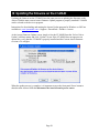
1
User Manual
Please Note: The LT-MADI requires your Aurora converter to have Firmware Version 24 or
later. Any Aurora shipped from Lynx Studio Technology prior to September 9th, 2009 will have
previous firmware installed in it.
For information about updating the Aurora’s firmware to a compatible revision, see Section 3.3
Operation Requirements.
Lynx Studio Technology, Inc.
www.lynxstudio.com
[email protected]
User Manual
Table of Contents
1
2
3
Introduction............................................................................................................................. 1
Features ................................................................................................................................... 1
Before You Begin ................................................................................................................... 2
3.1
Contents .......................................................................................................................... 2
3.2
Optional Equipment ........................................................................................................ 2
3.3
Operation Requirements ................................................................................................. 2
4
Nomenclature used in this manual.......................................................................................... 3
5
Warranty Registration............................................................................................................. 3
5.1
Locating the Serial Number of Your LT-MADI............................................................. 3
6
Installation Procedure ............................................................................................................. 4
7
External Connections ............................................................................................................ 10
7.1
MADI 56/64 Channel Modes........................................................................................ 10
7.2
LT-MADI 16/32-channel modes .................................................................................. 12
7.2.1
16-channel mode................................................................................................... 12
7.2.2
32-channel mode................................................................................................... 12
7.2.3
Switching and verifying mode .............................................................................. 13
7.2.4
What about an Aurora 8? ...................................................................................... 13
7.3
Connector Types ........................................................................................................... 14
7.4
Configuring Multiple Auroras ...................................................................................... 14
7.4.1
Unit ID Switch ...................................................................................................... 15
7.4.2
Delay Compensation............................................................................................. 16
7.4.3
Unit Bypass........................................................................................................... 16
7.4.4
Daisy-Chaining Units............................................................................................ 16
7.4.5
Possible Combinations.......................................................................................... 17
8
Clock Settings ....................................................................................................................... 19
9
Routing and Channel Mapping ............................................................................................. 21
9.1
Routing Logic ............................................................................................................... 21
9.1.1
MADI Output Routing.......................................................................................... 21
9.1.2
Input Routing ........................................................................................................ 22
10
Updating the firmware on the LT-MADI ......................................................................... 26
11
Specifications.................................................................................................................... 27
12
Support.............................................................................................................................. 28
12.1 Lynx Website Support Resources................................................................................. 28
12.2 Telephone Support ........................................................................................................ 28
12.3 Registering your LT-MADI.......................................................................................... 28
12.4 Return Policy ................................................................................................................ 28
13
Warranty Information ....................................................................................................... 29
1 Introduction
Thank you for purchasing the LT-MADI™! We are proud to provide you with a reliable,
professional-quality product for your digital audio requirements.
This manual provides basic information to help you get started. Additional information is
available via our web site and email support. Please refer to Section 12, Support, at the end of
this manual for support contact information.
The LT-MADI is a 64-channel LSlot interface that is designed to allow the Aurora professional
audio AD/DA converters to be used with MADI (Multichannel Audio Digital Interface)
compatible mixers, multi-track recorders and other audio devices. The LT-MADI features
coaxial and optical connections, allows synchronization to MADI input streams, and allows
daisy-chaining of LT-MADI equipped Auroras. Each LT-MADI card can be configured for 56 or
64 channel operation. Connections up to 100 meters with coaxial cable and 2000 meters with
fiber optic cable are supported.
2 Features
¾ Two BNC/Coaxial and Two SC-Type Optical connectors per card.
¾ Each LT-MADI card is capable of up to 64-channels of I/O at sample rates up to 48kHz, 32channels at 88.2/96kHz, and 16-channels at 176.4/192kHz.
¾ An Aurora 16 can be configured for 32-channel or 16-channel operation. In 32-channel
mode, all Analog AND AES/EBU channels can be routed to and from MADI I/O. In 16channel mode, Analog OR AES/EBU channels can be routed to and from MADI I/O. An
Aurora 8 will only operate in 16-channel mode, using 8 analog and 8 AES/EBU channels.
¾ Up to four Auroras can be daisy-chained together for a maximum of 64 channels of I/O.
¾ Lynx proprietary SynchroLock™ technology can be used to reduce jitter when Aurora is a
clock slave or to provide stable, low jitter clock to downstream devices. This is especially
important and highly recommended for MADI clocking due to its inherent high jitter level.
¾ Supports MADI 64-channel operation as well as legacy 56-channel operation.
¾ Routing and configuration options available via Aurora Remote Control software application.
¾ Supports Cable lengths up to 100 meters with coaxial, and up to 2000 meters with fiber optic
cable.
¾ Programmable firmware onboard allows field updates to expand device utility and features.
¾ Automatic Delay Compensation insures sample accuracy with multiple, daisy-chained
Auroras.
¾ Easily installed into Aurora.
Page 1
3 Before You Begin
We recommend that you read through the manual to acquire an overview of the installation
procedure and use of the LT-MADI. This manual will presume a working knowledge of the
Aurora converter. For additional information, please refer to the Aurora owner’s manual.
3.1 Contents
Verify that you received the following in the LT-MADI shipping carton:
• LT-MADI card in cushioned antistatic bag
• Warranty Registration Card
• Lynx Installation CD
• 1/2” Standoff Post
3.2 Optional Equipment
75-ohm Coaxial Cable with BNC connectors or Fiber optic cable for connection to MADI
devices.
3.3 Operation Requirements
The LT-MADI requires your Aurora converter to have Firmware Version 24 or above. This
should be verified prior to installing and configuring the LT-MADI card. To determine what
firmware revision your Aurora has, press the TRIM and POWER buttons at the same time with
the power to the Aurora off. If the LED flashes over the numbers 2 & 4 or above (i.e. 2 & 5, 3 &
1, etc.), then your unit is compatible with the LT-MADI. If pressing Power and Trim does not
cause any LEDs to flash, or causes a single number to flash, then your unit needs to be updated.
The Aurora firmware can be updated by a Windows PC or OSX Macintosh with a Lynx AES16
PCI audio interface installed, or via MIDI (note: firmware revision 13 or above is required for
MIDI programming). The Aurora firmware updater program is available for download from the
Lynx website at Support > Downloads. If your unit requires an AES16 to update because it has
firmware revision 12 or earlier, and you do not have access to one, there are two options for
customers within the USA and Canada:
•
•
Option 1: Send the Aurora and LT-MADI to Lynx Studio Technology in California. We
will update the Aurora, install the LT-MADI and do a full diagnostic test within one day
of receipt. It will be return shipped via 2-Day Air.
Option 2: Lynx Studio Technology will loan you an AES16 for updating the firmware in
your Aurora. For more information on the procedure and any questions, contact
[email protected] or call 714-545-4700 extension 206.
If you are outside of the USA or Canada, please contact your local distributor for
additional firmware update options.
Page 2
4 Nomenclature used in this manual
The following typographic conventions are used in this manual:
¾ ALL UPPER CASE TEXT refers to a specific parameter selection control (i.e. SYNC
SOURCE) or a cable connection.
¾ Text in quotation marks indicates a parameter selection value or menu option (i.e. “EXT”).
¾ Phrases, such as: Click Setups Mixer > About Aurora Remote…, use the greater than symbol
(“>”) to indicate multiple menu options or mouse selections within a software control
context.
5 Warranty Registration
We are committed to providing you with the best service possible. To help us serve you better,
please be sure to register your LT-MADI using one of the following methods:
•
Fill out and mail the Warranty Registration Card included with your LT-MADI.
•
Register on the web at:
https://www.lynxstudio.com/support_register.asp
Once you are registered you will automatically receive notifications of new products and
upgrades.
5.1 Locating the Serial Number of Your LT-MADI
To register your LT-MADI, you must supply its serial number. The serial number is located on a
label attached to the back (solder-side) of the LT-MADI board, and also on the shipping carton.
Page 3
6 Installation Procedure
1.
Remove the AC power cord and take the top off of the Aurora 16 or Aurora 8. There are
seven large screws plus one small screw near the center of the front faceplate.
2.
Before installing the LT-MADI card, slide switch 4 (labeled W4 on PCB) of SW1 to the
OFF position (towards back panel)
If you are updating an older Aurora that has jumper pins at JP6, instead of the W4
switches, please call Lynx Technical Support for instructions.
3.
Remove the LSlot Expansion Port cover above the AES I/O Ports by removing the two
mounting screws. Set these two screws aside, as they will be used to secure the LTMADI after installation.
Page 4
4.
Remove the screw from the Aurora circuit board that is adjacent to the JP1 connector and
the white serial number/barcode label. Set the screw aside for reuse.
5.
Install the standoff post (included with the LT-MADI) in this same hole.
Page 5
6.
Grounding yourself to the earth ground, remove the LT-MADI from its protective static
bag.
7.
Set the appropriate dip switches on the LT-MADI. These settings are specific to the
context of use, so it is strongly encouraged to read the associated sections of the manual
before determining which settings are correct. The following settings are configured from
the Dip Switches on the LT-MADI card:
Device Order: These switches establish whether the Aurora is to be used as the only
device in the MADI system, or within a multiple Aurora configuration. See Section 7.4.1
Unit ID Switch for a detailed explanation.
Page 6
Note that when the Aurora is the only MADI device connected, switch SW3 should be
OFF and switches SW1 and SW 2 should be ON (this is the default state for a new LTMADI card). When multiple Auroras are used, each needs a unique device ID to be
correctly integrated, and SW3 should be ON. The table below will describe the pertinent
switch settings for single unit mode and any of the four device IDs:
SW1
SW2
SW3
UNIT_ID
SWITCH
Back of Aurora
ON
ON
ON
OFF
C&K
SDA04
Single Aurora
1
2
3
4
Back of Aurora
ON
ON
ON
ON
C&K
SDA04
Device 0
1
2
3
4
Back of Aurora
ON
OFF
ON
ON
C&K
SDA04
Device 1
1
2
3
4
Back of Aurora
ON
ON
OFF
ON
C&K
SDA04
Device 2
1
2
3
4
Back of Aurora
ON
OFF
OFF
ON
C&K
SDA04
Device 3
1
2
3
4
16-channel mode: This is applicable to an Aurora 16 that is configured for 16-channel
mode. It is not applicable for an Aurora 8 or an Aurora 16 in 32-channel mode. For an
explanation of 16 and 32-channel mode, see Section 9.1.1 MADI Output Routing. The
SW4 determines whether the Aurora’s ANALOG or DIGITAL Inputs will route to the
16-channel MADI stream. For more information, see Section 9.1.1.2 Aurora 16 in 16channel mode.
SW4
Selection when in 16-channel mode
OFF
DIGITAL INPUT
SWITCH
Back of Aurora
ON
1
C&K
2
SDA04
3
4
Back of Aurora
ON
ON
C&K
SDA04
ANALOG INPUT
1
Page 7
2
3
4
8.
Set the JP2 jumper for the MADI 56 or 64 channel modes. MADI devices can utilize 56
channel operation or 64 channel operation. The LT-MADI inputs auto-detect the
appropriate mode, but the outputs must be configured to work correctly with MADI
devices receiving streams from the LT-MADI outputs. It is crucial to consult the
documentation for your MADI equipment to determine which mode is appropriate. See
MADI 56/64 Channel Modes. 64 channel mode is the LT-MADI default state.
9.
Attach the multi-pin connector on the back edge of the LT-MADI to the LSLOT
connector (JP1) on the Aurora mainboard. The LT-MADI LSLOT connector has a
protective sheath to insure that the pins line up correctly with the Aurora LSLOT
receptacle. When the LT-MADI connector pins appear to be lined up correctly with the
Aurora LSLOT connector press gently until the connector snaps into place. In some
cases, the board may need to be gently flexed for the LSLOT connector pins to line up
correctly with JP1 on the Aurora mainboard.
Use caution to insure that the pins line up as shown. Incorrect installation could
damage the unit.
Page 8
10.
Secure LT-MADI with three screws; one on the standoff and two from the back panel of
Aurora. Keep screws loose until LT-MADI is properly aligned, then tighten snugly, but
do not overtighten.
11.
Reinstall the Aurora lid using the eight screws that had been removed. Do not over
tighten the small screw near the center of the front faceplate as it is easily damaged.
12.
Plug in and power up the Aurora using the front panel standby switch. You can see the
LT-MADI from the slits in the Aurora lid. If LED6 on the LT-MADI lights up green,
then the installation was successful. If LED6 does not light, unplug the Aurora and remount the LT-MADI, making sure that it is securely attached. Then plug in and power up
again. If LED6 still does not light, contact Lynx Customer Support (714-545-4700
extension 206).
Page 9
7 External Connections
MADI (Multichannel Audio Digital Interface), also known as AES10, is an AES approved
digital audio standard. Originally conceived for use with Digital Consoles, MADI has since
expanded into other audio contexts where high channel count audio transfers are required, such
as broadcast, installations, live sound, video post-production, etc. MADI is distinct from other
common digital audio standards by the number of channels supported per cable connection.
Where other popular standards (AES/EBU, ADAT Lightpipe, TDIF) carry up to 8 channels per
connection, MADI is capable of carrying up to 64-channels per connection.
MADI is a point-to-point interface, with separate cable connections carrying input and output
signals. There are some variations in how MADI is implemented that are important to consider
when configuring your system. These options, as they apply to the LT-MADI card, are explored
below.
7.1 MADI 56/64 Channel Modes
Originally, the MADI standard defined a maximum of 56-channels per connection at 100 Mbit/s.
In 2001, the specification was expanded to support 64-channel operation at 125 Mbit/s. 64channel operation was conceived for cases where an exact sampling frequency was to be
provided, as is typical with modern digital equipment.
MADI operates as a stream of 64 channels, with connected devices occupying a particular
number of channels in that stream. For instance, when operating in 64-channel mode up to four
16-channel devices can be plugged into this stream, as long as their device IDs are unique.
The LT-MADI card supports 56 and 64-channel operation. Consult the operation manual for the
hardware that you will be connecting to the LT-MADI to determine if it supports 64 or 56
channel operation.
Incoming MADI streams are analyzed for 56 or 64 channel operation and the LT-MADI receiver
is automatically adjusted. For output streams, the card needs to be configured for 56-channel or
64-channel mode by setting the jumper on J1. See illustration below:
Page 10
64-channel mode is the default. If this is a new installation and your connected hardware
supports 64-channel mode, then no changes are required.
Maximum channel count is also dependent on the operating sample rate. In 56-channel mode, the
LT-MADI is capable of 56 channels at 44.1kHz or 48kHz sample rates, 28 channels at 88.2 or
96kHz and 14 channels at 176.4 or 192kHz. In 64-channel mode, the LT-MADI is capable of 64
channels at 44.1kHz or 48kHz sample rates, 32 channels at 88.2 or 96kHz and 16 channels at
176.4 or 192kHz. Also consider that the maximum number of channels that can be achieved
from a single Aurora 16 is 32. Greater than 32-channels is possible only in a system with
multiple Auroras.
Page 11
7.2 LT-MADI 16/32-channel modes
When used with some LSLOT expansion cards like the LT-MADI, an Aurora 16 can be
configured to operate as a 16-channel or a 32-channel device, depending on your ultimate I/O
needs. 16-channel mode is ideal for streaming audio via MADI to the Auroras Analog I/O OR
AES I/O, but not both. In contrast, 32-channel mode provides access to all AES/EBU and
ANALOG channels on the Aurora, simultaneously and independently.
7.2.1 16-channel mode
In 16-channel mode, the LT-MADI extracts 16 audio channels from the incoming MADI stream
and sends them to the Analog and AES outputs simultaneously. The signals are mirrored so that
signals delivered to Analog Output 1 would also be sent to AES Output 1.
For the outgoing MADI Stream, the LT-MADI card can be set to route audio from the Analog
inputs OR the AES inputs, but not both at the same time. Selecting Digital Inputs or Analog
Inputs is done with SW4 switch on the LT-MADI card. See below:
SW4
Selection when in 16-channel mode
OFF
DIGITAL INPUT
SWITCH
Back of Aurora
ON
1
C&K
2
SDA04
3
4
Back of Aurora
ON
ON
C&K
SDA04
ANALOG INPUT
1
2
3
4
The Analog/Digital selection is global. You cannot, for instance, send 8 channels from the
Analog inputs and 8 channels from the AES inputs to the MADI outputs.
Note: this switch is only applicable for an Aurora 16 set to 16-channel mode, and is not pertinent
for use with an Aurora 8 or an Aurora 16 set to 32-channel mode.
7.2.2 32-channel mode
In 32 channel mode and device ID 0, the LT-MADI is capable of routing 32 audio channels from
the incoming MADI stream and sending channels 1-16 to the Aurora Analog outputs, and
channels 17-32 to the AES outputs. Similarly, the signals from the Analog Inputs can be routed
to MADI Outputs 1-16, and signals from the AES Inputs can be routed to MADI outputs 17-32
(note that if the LT-MADI has device ID 1, then the corresponding MADI channels will be 3348 and 49-64).
As an example, a signal sent to MADI input channel 3 will be delivered to Aurora analog output
3, whereas a signal sent to MADI input channel 18 will be delivered to AES Output 2
(sometimes labeled 1R). See Section 9: Routing and Channel Mapping for more information.
Page 12
7.2.3 Switching and verifying mode
Switching between 16-channel and 32-channel mode is done by holding down the TO ANALOG
OUT button on the Aurora front panel for one-half second. All of the Aurora LEDs will flash to
confirm the switch has occurred. There are two ways to confirm that a unit is in 16-channel or
32-channel mode:
1. Run the Aurora Remote Control software via MIDI. The Aurora Remote Control
software is available for OSX or Windows computers, and is on the Lynx Installation
disk, or it can be downloaded from www.lynxstudio.com > Support > Downloads. On the
Analog I/O page, the LSLOT CHANNEL MODE label will display either “32-channel”
or “16-channel”.
For more information about the Aurora Remote Control software, see Aurora Remote
Control Software.
2. The Aurora channel state can be determined by putting the Aurora into “demo mode”.
This is done by pressing down the TRIM and POWER buttons at the same time with the
power to the Aurora off. This will cause the Aurora LEDs to flash sequentially from left
to right. In addition to this, if the three LEDs around the TO ANALOG OUT button flash
together repeatedly, then the Aurora is in 32-channel mode. If they do not, then it is in
16-channel mode.
7.2.4 What about an Aurora 8?
There is no equivalent mode option for an Aurora 8. An Aurora 8 will always operate in 16
channel mode, where the analog and digital inputs and outputs are independent.
With an Aurora 8, the LT-MADI extracts 16 audio channels from the MADI inputs and routes
channels 1-8 to the Analog Outputs, and channels 9-16 to the AES outputs. Similarly, the signals
from the Analog inputs are routed to MADI outputs 1-8, signals from the AES Inputs are routed
to MADI outputs 9-16.
Page 13
7.3 Connector Types
MADI is typically carried on one of two connector and cable types, and both are supported by
the LT-MADI card. The older, original method is coaxial cable with BNC connectors. The LTMADI requires 75 Ohm coaxial cable. Cables of this sort are inexpensive and easily procurable.
The alternative, more typical with newer MADI devices, uses SC-Type Optical connections with
network fiber optic cables. There are a number of benefits to this connection type including
markedly less jitter on the digital signal. One of the biggest differences between the two
connection types is maximum cable length. Cable runs of up to 2000 meters are possible with the
fiber optic connection, whereas coaxial has a maximum cable length of 100 meters.
Two types of glass fiber optic cables can be used:
• Cables with an internal diameter of 50 µm and an external diameter of 125 µm are
typically orange and referred to as 50/125 Network Cables.
• Cables with an internal diameter of 62.5 µm and an external diameter of 125 µm are
typically blue and referred to as 62.5/125 Network Cables.
Signals passing to the LT-MADI outputs are mirrored to both the coaxial and fiber optic ports.
Potentially, both can be connected at the same time in cases where it is useful to have duplicate
streams sent to different devices for recording or monitoring.
For MADI input signals, the hardware supports only using either the optical or coaxial ports, but
not both simultaneously. The MADI receiver auto-detects which connection has a valid MADI
signal, and selects that as the default input port. If both connections contain a valid MADI signal,
then priority is given to the fiber optic port.
Tips: LED1 being ON indicates that there is a valid MADI signal on an input port, otherwise, if
the incoming MADI signal is invalid, LED1 will blink. LED2 being ON indicates that both
MADI output ports are enabled and are passing MADI data.
7.4 Configuring Multiple Auroras
The LT-MADI was designed so that up to four Auroras could be daisy-chained through a single
MADI connection. This allows great flexibility in creating a high-channel count system that is
simple to manage and use. Any combination of Aurora 16s and/or Aurora 8s can be combined to
a channel maximum of 64-channels.
As described earlier, each MADI connection carries up to 64 channels divided into 16-channel
clusters. Aurora I/Os occupy these clusters based on several factors:
• Aurora Type (8 or 16)
• Channel Mode (16 or 32 – Pertinent to Aurora 16 only, see Section 7.2.)
• Sample Rate (1X – 44.1/48kHz, 2X – 88.2/96kHz, or 4X – 176.4/192kHz)
• Unit ID settings (LT-MADI Switches SW1 – SW2)
Page 14
With this number of influential factors, there are a significant number of possible combinations.
A key element to multi-Aurora configurations is correctly setting the Unit ID switch on each LTMADI card.
7.4.1 Unit ID Switch
When multiple Auroras are daisy chained via MADI, it is essential that they each occupy unique
positions in the MADI stream. MADI is a serial medium, so devices in a MADI daisy chain will
be mounted in a sequential fashion. The Unit ID switch on each LT-MADI card determines the
order in which devices are integrated into the MADI stream.
The Unit ID is determined by the position of the SW1 and SW2 switch on the LT-MADI card. It
is possible to set this switch after the card is installed, although there should be no AC power to
the Aurora when this modification is made.
The unit ID should also correspond to the physical position of each unit in the daisy-chain. For
instance, the output of Unit 0 should connect to the input of Unit 1. The output of Unit 1 should
connect to the input of Unit 2, etc. For a system that is used in different settings, it is important
to make note of the device IDs for each Aurora so that they are not connected in the wrong order.
Switch 3 toggles the delay compensation on or off. Delay Compensation should be ON whenever
more than one Aurora is used in a MADI daisy-chain (see section 7.4.2), and OFF whenever a
single Aurora is used. The table below will describe the pertinent switch settings:
SW1
SW2
SW3
UNIT_ID
SWITCH
Back of Aurora
ON
ON
ON
OFF
C&K
SDA04
Single Aurora
1
2
3
4
Back of Aurora
ON
ON
ON
ON
C&K
SDA04
Device 0
1
2
3
4
Back of Aurora
ON
OFF
ON
ON
1
Page 15
C&K
SDA04
Device 1
2
3
4
Back of Aurora
ON
ON
OFF
ON
C&K
SDA04
Device 2
1
2
3
4
Back of Aurora
ON
OFF
OFF
ON
C&K
SDA04
Device 3
1
2
3
4
The factory default state of these Switches is for Single Aurora operation.
7.4.2 Delay Compensation
Each device in a MADI chain operates a number of samples behind or ahead of the previous
device, due to latencies intrinsic to the transportation of MADI data through the daisy-chain.
Normally, the result of this disparity would be that streams from multi-unit systems would NOT
be sample aligned. The LT-MADI has a mechanism to correct for this disparity. Internal delay
compensation for each unit insures that analog signals are sample aligned, even with four units
connected. The amount of delay compensation that is applied is determined by the Unit ID on
the LT-MADI card. For that reason, it is important that the Auroras are daisy chained consistent
with the Unit ID position (i.e. Device 0 into Device 1 into Device 2 etc.). Delay Compensation,
as stated previously, is turned ON with the SW3 switch and should always be ON for multiAurora systems.
The delay compensation affects all Analog and AES/EBU inputs and outputs, at all sample rates.
7.4.3 Unit Bypass
When all MADI channels are being deployed by Auroras on a chain, additional Auroras are put
in bypass mode (MADI in and out are bypassed). Bypass is relative to the sample rate. If, for
instance, 4 Auroras in 16-channel mode are chained together at 44.1/48 kHz sample rates, I/O
from all 4 units will be utilized. At an 88.2/96 kHz sample rate, only the first two units in the
chain will be utilized and the last two put into Bypass mode. This is because at the 2X sample
rates MADI supports a maximum of 32-channels. LED5 being turned ON (green) indicates that
the LT-MADI card is in bypass mode.
Section 7.4.5 details several common multi-Aurora scenarios and which units are in bypass mode
at different sample rates.
7.4.4 Daisy-Chaining Units
In MADI systems where signal flow is ingoing and outgoing, connected devices typically form a
loop. In systems where audio only travels either upstream or downstream (ie. either recording or
playback, but not both), then creating a complete daisy-chained loop is not necessary.
The graphics below detail some common scenarios to use as a configuration guide.
Page 16
In a system where there is a MADI device that is both the signal source and final destination,
connected devices form a loop with outputs connected to inputs through each device in the chain.
The example below shows two Aurora 16s connected to a MADI source/destination:
In the case of a system when the MADI source and destination are different devices, the
configuration would look like this:
Alternatively, it is possible to have the MADI stream only move in one direction. In this case it is
not necessary for the MADI stream to form a complete loop. The example below details a MADI
system used for playback only:
Since signals are mirrored to the Optical and Coaxial outputs simultaneously on the LT-MADI, it
is possible to mix coaxial and optical connections types in a single MADI daisy chain. However,
keep in mind that the optical port will be prioritized as the input connection, so generally you
would not want to have both optical and coaxial input connections made to the same Aurora.
7.4.5 Possible Combinations
Since there are a variety of factors that impact the channel count and I/O types in a multi Aurora
system, this section will help you identify what hardware and settings are necessary to achieve
several common configurations.
Page 17
7.4.5.1
32-channels of Analog I/O, No AES
For this configuration you will need two Aurora 16s. The first Aurora in the chain should be
configured as Device 0 and the second as Device 1. Only the Analog I/O on the Aurora will be
connected to signal sources and destinations.
16/32
channel
mode
Active
Active
Active
Channels
Channels
Channels
44.1/48kHz 88.2/96kHz 176.4/192kHz
SWITCH
Back of Aurora
Aurora 16
- Device
0
16Channel
Mode
ON
C&K
1
SDA04
2
3
Analog
1-16
Analog
1-16
Analog
1-16
Analog
1-16
Analog
1-16
ByPass
4
Back of Aurora
Aurora 16
- Device
1
7.4.5.2
16Channel
Mode
ON
C&K
1
SDA04
2
3
4
64 Channels of Analog I/O, No AES
For this configuration you will need four Aurora 16s. They should be configured, in order, as
Devices 0 – 3. Only the Analog I/O on the Aurora will be connected to signal sources and
destinations.
16/32
channel
mode
Active
Active
Active
Channels
Channels
Channels
44.1/48kHz 88.2/96kHz 176.4/192kHz
SWITCH
Back of Aurora
Aurora
16 Device 0
16Channel
Mode
ON
1
C&K
2
SDA04
3
Analog
1-16
Analog
1-16
Analog
1-16
Analog
1-16
Analog
1-16
ByPass
Analog
1-16
ByPass
ByPass
Analog
1-16
ByPass
ByPass
4
Back of Aurora
Aurora
16 Device 1
16Channel
Mode
ON
1
C&K
2
SDA04
3
4
Back of Aurora
Aurora
16 Device 2
16Channel
Mode
ON
1
C&K
2
SDA04
3
4
Back of Aurora
Aurora
16 Device 3
16Channel
Mode
ON
1
C&K
2
SDA04
3
4
Page 18
7.4.5.3
32 Channels of Analog I/O AND 32 Channels of Digital I/O
For this configuration you will need two Aurora 16s. They should be configured, in order, as
Devices 0 – 1. All Analog I/O and AES/EBU on both Auroras will be connected to signal
sources and destinations.
16/32
channel
mode
Aurora
16
- Device
0
Aurora
16 Device
1
7.4.5.4
Active
Active
Active
Channels
Channels
Channels
44.1/48kHz 88.2/96kHz 176.4/192kHz
SWITCH
Back of Aurora
32Channel
Mode
ON
C&K
1
2
SDA04
3
4
Analog
1-16,
AES 1-16
Analog
1-16,
AES 1-16
Analog
1-16
Analog
1-16,
AES 1-16
ByPass
ByPass
Back of Aurora
32Channel
Mode
ON
C&K
1
2
SDA04
3
4
16 Channels of AES I/O, No Analog
For this configuration you will need one Aurora 16 that should be configured as a single unit.
Only the Digital I/O on the Aurora will be connected to signal sources and destinations.
16/32
channel
mode
Aurora
16 –
Single
Unit
16Channel
Mode
Active
Active
Active
Channels
Channels
Channels
44.1/48kHz 88.2/96kHz 176.4/192kHz
switch
Back of Aurora
ON
C&K
SDA04
AES 1-16
1
2
3
AES 1-16
AES 1-16
4
8 Clock Settings
In any audio system with more than one digital device, it is ideal for one master clock to provide
synchronization to all connected devices. There are several options for configuring the Aurora to
send or receive a clock signal within a MADI environment.
MADI equipment and other digital devices can slave to the sample clock generated by the
Aurora, or the Aurora can be configured to receive clock from other digital devices. It is also
possible to have a dedicated clock source that provides clock to both the Aurora and every other
digitally connected device. In fact, if more than two digital I/O devices will be integrated into
your system, we strongly recommend using some form of clock distribution to insure proper
clock synchronization.
Page 19
The table below details SYNC SOURCE choices for the Aurora as pertinent to use within a
MADI-based system. Please see section 2.4 of the Aurora manual for general information about
available clock settings and clocking considerations with the Aurora.
EXT - External
Clock signals from Aurora WORD CLOCK input. In general, WORD
CLOCK is the preferred means to clock devices (including multiple
Auroras) in a MADI system. Auroras can be daisy-chained via wordclock,
or recipients of wordclock distribution. In a simple system (i.e. one Aurora
and a MADI source/destination), it is still ideal to use Word Clock sync
between the Aurora and the other MADI device(s) as a means to reduce
jitter system-wide.
EXT/2 - External Divided by 2
Used if the word clock is half the rate of the desired sample rate, which
would be more typical in legacy systems.
AES A – Port A Digital Input
Word Clock recovered from the Port A digital input (or AES channels 1-4
on an Aurora 8). In a MADI-based system this would be an unusual Sync
Source. It could be a solution when the Aurora is used with a MADI device
that does not have wordclock sync options but does have AES/EBU ports,
in order to avoid some of the issues with clocking via MADI connections.
AES B – Port B Digital Input
Word Clock recovered from the Port B digital input, like above. On an
Aurora 8, this would be signals from AES inputs 5-8.
LSLOT
Sample clock derived from the incoming MADI signal.
There are some specific issues to be aware of when clocking via MADI:
Clock signals derived from a MADI stream contain high-levels of jitter
because the clock rate for MADI I/O is asynchronous with the sample rate.
Thankfully, the Aurora was designed with Lynx’s SynchroLock technology
specifically to correct for jitter in incoming signals. It is capable of jitter
reduction up to 3000:1. Considering the poor jitter performance with the
MADI protocol, we strongly recommend leaving SynchroLock ON when
clocking via LSLOT.
Additionally, MADI devices can only detect the base (1x) rate of the
incoming MADI stream. Therefore it is necessary to manually set the
Aurora to the desired Sample Rate when using LSLOT as the SYNC
SOURCE at sample rates > 48kHz (ie. 2x, 4x rates). For instance, if the
incoming MADI signal is operating at 88.2kHz, the Aurora will default to a
sample rate of 44.1kHz. Click the SAMPLE RATE button on the Aurora
front panel to toggle between 2x, 4x, 1x sample rates and set the Aurora to
88.2kHz for proper clock operation.
Page 20
9 Routing and Channel Mapping
Sending audio signals into and out of the LT-MADI is straightforward. Routing can be initiated
globally from the Aurora front panel or on a per-channel basis by using the Aurora Remote
Control software.
9.1 Routing Logic
The LT-MADI card implements a routing scheme whereby signals sent to Analog or Digital
inputs on the Aurora get automatically routed to appropriate MADI Outputs. Signals going into
MADI Inputs however can be routed to the AES, Analog or MADI Outputs.
The selections of 16/32 channel mode, and the Analog/Digital switch for 16-channel mode are
pertinent to the routing behavior, so it is important to be clear on the state of the Aurora in this
regard to understand the results.
9.1.1 MADI Output Routing
MADI Output routing is hard wired and cannot be altered by the user. The state of the TO
ANALOG OUT and TO DIGITAL OUT buttons on the Aurora front panel have no impact on
the MADI Output routing scheme. Signals sent to an Aurora input (analog and/or digital) get
routed directly to a MADI output. The block of MADI output channels that will be affected
depends on the LT-MADI’s device ID, whether the Aurora is operating in 16 or 32 channel
mode (for an Aurora 16 only), and the operating sample rate.
9.1.1.1
Aurora16 in 32-channel mode
In 32-channel mode, all 16 Analog AND all 16 AES/EBU Inputs send audio streams to the
MADI outputs. Analog Inputs 1-16 are routed directly to MADI outputs 1-16, and Aurora Digital
Inputs 1-16 are routed directly to MADI Outputs 17-32. It is important to consider the active
sample rate as this has pertinence to the number of actual MADI channels available. See the
reference charts in section 7.4.5: Possible Combinations
9.1.1.2
Aurora 16 in 16-channel mode
In 16-channel mode, the Aurora 16 will pass up to 16 channels of audio to the MADI outputs. If
the LT-MADI card is set to “ANALOG”, then signals sent to the 16 Analog inputs will be routed
to the MADI outputs, and signals sent to the Aurora’s Digital inputs will not. Conversely, if the
LT-MADI card is set to “DIGITAL”, then signals sent to the 16 Digital inputs will be routed to
the MADI outputs, and signals sent to the Analog inputs will not.
9.1.1.3
Aurora 8
An Aurora 8 will always be a 16-channel device when used with the LT-MADI. All 8 Analog
AND all 8 AES/EBU Inputs send audio streams to the MADI outputs. Analog Inputs 1-8 are
routed to MADI Outputs 1-8, and Digital Inputs 1-8 are routed to MADI Outputs 9-16.
Page 21
9.1.2 Input Routing
Signals from MADI inputs can be routed to Aurora Analog and/or AES/EBU Outputs. The
Aurora will need to be configured for this routing scheme and will not operate this way in its
default state. Input routing can be set globally from the Aurora Remote Control software or from
the Aurora front panel.
Additionally, input routing can also be initiated by the user on a per-channel basis with the
Aurora Remote Control software.
9.1.2.1
Global Routing
Global routing is achieved from the Aurora Remote Control software or from the Aurora front
panel. From the front panel, the buttons labeled TO ANALOG OUT and TO DIGITAL OUT are
where appropriate routing would be established. Since the LT-MADI is an LSLOT device,
Choosing “LSLOT In” as the Source for TO ANALOG OUT would route signals from MADI
inputs to the Aurora’s Analog outputs. Choosing “LSLOT In” as the Source for TO DIGITAL
OUT would route signals from MADI inputs to the Aurora’s AES/EBU DIGITAL outputs.
This setting will be affected by the 16/32-channel mode states for an Aurora 16. In 32-channel
mode, MADI inputs 1-16 will route to Analog outputs 1-16. MADI inputs 17-32 would route to
Aurora Digital outputs 1-16.
In 16-channel mode, if the LT-MADI card is set to “ANALOG”, then signals sent to the 16
MADI inputs will be routed to the Aurora’s Analog outputs, and signals sent to the Aurora’s
Digital inputs will not. Conversely, if the LT-MADI card is set to “DIGITAL”, then signals sent
to the 16 Digital inputs will be routed to the MADI outputs, and signals sent to the Analog inputs
will not.
With an Aurora 8, MADI inputs 1-8 will be sent to the Aurora’s Analog outputs, and MADI
inputs 9-16 will be sent to the Aurora’s Digital outputs.
The following chart will detail global LT-MADI Input routing with the various configurations of
an Aurora 8 or Aurora 16
Unit
Aurora 16
Aurora 16
Aurora 16
Aurora 8
16/32
Digital or
channel
Analog
mode
mode
32-Channel
N/A
Mode
16-Channel SW4 switch
Mode
= Analog
16-Channel SW4 switch
Mode
= Digital
N/A
N/A
MADI
Inputs 1-8
Route to
Analog
Out 1-8
Analog
Out 1-8
Digital
Out 1-8
Analog
Out 1-8
Page 22
MADI
Inputs 9-16
Route to
Analog
Out 9-16
Analog
Out 9-16
Digital
Out 9-16
Digital
Out 1-8
MADI
Inputs 1724 Route to
Digital Out
1-8
MADI
Inputs 2532 Route to
Digital Out
9-16
N/A
N/A
N/A
N/A
N/A
N/A
9.1.2.2
Per Channel Routing
In addition to global routing, an LT-MADI equipped Aurora is capable of routing MADI streams
to Aurora Analog and Digital outputs on a per-channel basis. MADI streams can also be
duplicated across multiple Aurora outputs. For instance, MADI input 1 and 2 can be routed to
Analog outputs 7 and 8, while MADI inputs 3 and 4 can be routed to Analog outputs 5 and 6
AND Digital out 1 and 2 at the same time.
Per-channel routing can only be initiated from the Aurora Remote Control software. The Aurora
Remote Control (ARC) application allows control of Aurora parameters from a convenient
software interface. It also provides accurate real-time metering for the Analog and Digital inputs
and outputs.
The ARC software can operate on an OSX or Windows PC computer via a Lynx AES16 audio
interface or MIDI. The software is available on the Lynx Installation CD, or can be downloaded
from www.lynxstudio.com > Support > Downloads.
9.1.2.2.1
Aurora Remote Control Software
The Aurora Remote Control (ARC) application allows control of Aurora parameters from a
convenient software interface. It also provides accurate real-time metering for the Analog and
Digital inputs and outputs.
After installation, the ARC can be run from the “Lynx Studio Technology” program group on a
Windows machine, or from “Applications” on an OSX installation.
The Aurora Remote Control Application allows the user to control output levels, route inputs to
outputs, change parameters, and view accurate meters for inputs and outputs on a connected
Aurora. Most parameter changes will be reflected both on the Aurora front panel and within the
software application.
Global routing can be set identically from the Aurora front panel or from the ARC application.
The selections available for TO ANALOG OUT and TO DIGITAL OUT are “ANALOG IN”,
“AES IN” and “LSLOT IN”. Additionally these buttons can be set to “Remote” mode by
pressing the appropriate button until the LEDs for all three choices are illuminated or by
selecting “Remote” as the source from within the ARC Digital I/O and Settings page.
In “Remote” routing mode, the Volume faders in the ARC become active, and audio signals can
be routed on a per-channel basis. Routing and volume controls for the Analog Outputs are
initiated from the “Analog I/O” page, and for the AES/EBU Digital Outputs from the “Digital
Page 23
I/O & Settings” page. The Aurora is capable of two sources per output at any sample rate.
LSLOT sources will represent MADI signals when an LT-MADI card is installed.
The features on the Output section of the “Analog I/O” page are described below:
q
These indicators will illuminate when three consecutive full-scale samples are detected
on the Aurora Analog inputs and outputs or when a summing overrun occurs on the
Aurora Analog outputs. The indicator will remain illuminated for 250ms.
w
These meters display the instantaneous peak level of audio being sent to the Aurora
Analog inputs and outputs.
e
These buttons allow the Analog input or output trims to be set. Each button allows groups
of fours channels to be toggled between +4dBu (the default) and -10dBV. This setting
will only appear on the Analog I/O page.
r
These tabs allow monitor source groups to be selected for the Analog outputs when
Remote Routing is utilized. The Aurora can be set for global routing (i.e. AES In routes
to Analog Out) or Remote Routing. With Remote Routing up to two sources (Source A
Page 24
and Source B) can be established for each output. For these custom monitor sources to be
active, the TO ANALOG OUT switch on the Digital I/O & Settings page must be set to
“Remote”. In this state all three LEDs for the TO ANALOG OUT button on the Aurora
front panel will be illuminated.
t
These buttons allow individual monitor sources to be selected for each analog output
when using Remote Routing. Clicking a button allows selection of any Analog, Digital or
LSLOT input source (LSLOT = MADI). Holding down the CTRL key while selecting a
source causes the remaining channels to be set sequentially (i.e. if you select LSLOT In 1
as the monitor source for Analog Out 1 while holding down the CTRL key, LSLOT In 116 will be assigned to Analog Out 1-16).
y
These faders allow control over the output level of each monitor source when in Remote
Routing mode. This level attenuation occurs in the digital domain, so it is recommended
to leave these faders in their default, maximum position in situations where the highest
fidelity is required. Holding down the SHIFT key on the keyboard while adjusting a
fader, will cause adjustment of channel pairs.
u
i
This display reveals the amount of attenuation, in dB, of a monitor source.
This button enables the mute function for the associated monitor source.
Any input sources assigned to an output can be assigned multiple times, for instance, a stream
coming in to MADI inputs 1 and 2, can be routed to Analog outputs 1 and 2, as well as Analog
outputs 9 and 10. With an Aurora 16 it is important to be aware of whether the Aurora is
operating in 16 or 32-channel mode. This will determine the number of MADI input channels
that will be available for routing.
Some examples of possible routing combinations would be:
Routing MADI input streams to Analog outputs AND routing Analog inputs to Analog outputs:
TO ANALOG OUT = “REMOTE”
Source A = LSLOT 1-16
Source B = Analog In 1-16
Routing 16-channels of MADI input streams to Analog out 1-16 AND Digital out 1-16:
TO ANALOG OUT = “Remote”
TO DIGITAL OUT = “Remote”
Analog Source A = LSLOT 1-16
Digital Source A = LSLOT 1-16
Sending a stereo MADI stream to 16 MADI outputs:
TO DIGITAL OUT = “Remote”
Digital Source A = LSLOT 1/2, LSLOT 1/2, etc.
Page 25
10 Updating the firmware on the LT-MADI
Updating the firmware on the LT-MADI uses the same process as updating the firmware on the
Aurora. With the most current Aurora Firmware Update program, a properly installed LT-MADI
can be selected as the device to program.
Instructions for downloading and running the Aurora Update program for Windows or OSX are
available at: www.lynxstudio.com > Support > Downloads > Product = Aurora.
At the Aurora Firmware Update screen, simply select the LT-MADI from the “Select Unit to
Update” pulldown menu, and click “Update” to run. If the LT-MADI does not appear as an
option here, verify that the LT-MADI is properly installed and the Current Aurora firmware
revision is 24 or higher.
When the update process is complete, it is important to press the front-panel Power button to
shut down the Aurora AND then disconnect the Aurora from its power source.
Page 26
11 Specifications
MADI PORTS
Type Coaxial input and output / fiber optic input and output
Channels In 56 Channel Mode:
56 channels @ 48kHz
28 channels @ 96kHz
14 channels @ 192kHz
In 64 Channel Mode:
64 channels @ 48kHz
32 channels @ 96kHz
16 channels @ 192kHz
CLOCK SYNCHRONIZATION
Clock Sources MADI or Aurora slave
ARCHITECTURE
Core FPGA-based core. Support for firmware field upgrades.
CONNECTIONS
I/O Ports (2) Bracket-mounted BNC connectors.
(2) Bracket-mounted fiber optic SC connectors.
Other LSlot expansion header (to Aurora)
SUPPORTED CABLE TYPES
Coaxial 75 Ohm with BNC connectors.
Fiber Optic 50/125 or 62.5/125 network cables with SC Type optical connectors
GENERAL
Host Interface Lynx proprietary LSlot™ Interface: 400 Mbps bi-directional
Requirements Aurora 16/Aurora 8 with Firmware Revision 24 or higher and
available LSlot expansion slot.
Size 3.0” H X 5.0” W X 0.75” D
EMI FCC and CE
Certifications
Shipping Weight 1 pound
Page 27
12 Support
We are devoted to making your experience with the LT-MADI trouble-free and productive. If the
operational sections of this manual did not help resolve your questions, several support options are
available to you:
12.1 Lynx Website Support Resources
Logging on to http://www.lynxstudio.com/support.html will provide several options for resolving your
support issues:
Support Ticket
For direct attention from the Lynx Technical Support Staff, registered users can submit a support
ticket online that details their problem and steps they’ve taken to resolve it. Most Support Ticket
submissions are responded to within 24 hours.
Frequently Asked Questions
An extensive catalog of FAQs derived directly from our most common tech support inquiries.
Our FAQ section is updated regularly and designed to allow users to find the answers to their
most common questions quickly.
Firmware and Driver Downloads
A library of current firmware and driver files are available for download and installation. Check
back regularly to insure that your Aurora and LT-MADI are up-to-date.
Lynx Support Forum
An online Lynx users support forum provides a venue for customers to post questions and issues
and receive responses from other users as well as Lynx technical administrators. Searching
previous posts is often an excellent way to uncover valuable information about Aurora operation
and troubleshooting. See http://www.lynxstudio.com/forum.
12.2 Telephone Support
Telephone support is available by calling +1 (714) 545-4700 extension 206 from 9AM to 5PM Pacific
Time, Monday through Friday, excluding United States Holidays.
12.3 Registering your LT-MADI
Lynx is committed to providing you with the best service possible. To help us serve you better, please be
sure to register your LT-MADI using one of the following methods:
¾ Fill out and mail the Warranty Registration Card included with your LT-MADI.
¾ Register on the web at: http://www.lynxstudio.com/ > Support > Register Your Products
Once you are registered you will automatically receive notifications of new products and upgrades.
12.4 Return Policy
If you have a unit that you suspect is defective or is malfunctioning contact Lynx technical support via
one of the means described above for diagnosis. If the technician determines that the unit is faulty, they
will issue an RMA number so you can send the unit in for repair. Units received without a valid RMA
number will be refused. All RMA numbers are valid for 30 days from the date of issue.
Page 28
13 Warranty Information
One year Free Labor / One year Parts Exchange
This product must be returned to the factory for repair.
Who Is Covered?
You must have proof of purchase to receive warranty service. A sales receipt or other document showing
when and where you purchased the product is considered proof of purchase. This warranty is enforceable
only by the original retail purchaser. To be protected by this warranty, the purchaser must complete and
return the enclosed warranty card or register online within 14 days of purchase.
What Is Covered?
Warranty coverage beings the day you buy your product. For one year thereafter, Lynx shall, at its sole
and absolute option, either repair or replace free of charge any product that proves to be defective on
inspection by Lynx or its authorized service representative. In all cases disputes concerning this warranty
shall be resolved as prescribed by law. All parts, including repaired and replaced parts, are covered only
for the original warranty period. When the warranty on the product expires, the warranty on all replaced
and repaired parts also expires.
What Is Excluded?
You warranty does not cover:
• Labor charges for installation or setup of the product.
• Product repair and/or part replacement because of misuse, accident, unauthorized repair or other
cause not within the control of Lynx.
• A product that requires modification or adaptation to enable it to operate in any country other than the
country for which it was designed, manufactured, approved and/or authorized, or repair of products
damaged by these modifications.
• Incidental or consequential damages result from the product, damage to property, damage based on
inconvenience or on loss of use of the product, and, to the extent permitted by law, damages for
personal injury. Some states do not allow the exclusion or limitation of incidental or consequential
damages, so the above limitation or exclusion may not apply to you.
• A product that is used for rental purposes.
To Get Warranty Service…
To obtain warranty service, the purchaser must first call or email Lynx at the email address or telephone
number printed in Section 12 to obtain a Return Authorization Number and instructions concerning where
to return the unit for service. All inquiries must be accompanied by a description of the problem. All
authorized returns must be sent to Lynx or an authorized Lynx repair facility postage prepaid insured and
properly packaged. Proof of purchase must be presented in the form of a bill of sale, canceled check or
some other positive proof that the product is within the warranty period. Lynx reserves the right to update
any unit returned for repair. Lynx reserves the right to change or improve design of the product at any
time without prior notice.
Lynx Studio Technology, Aurora and the Aurora Logo are trademarks of Lynx Studio Technology, Inc.
All other product or company names are the trademarks or registered trademarks of their respective
owners.
LT-MADI™ User Manual, October 14, 2009.
Copyright © 1998-2009, Lynx Studio Technology, Inc. All rights reserved.
Page 29