1
FORSCHUNGSZENTRUM ROSSENDORF
WISSENSCHAFTLICH-TECHNISCHE BERICHTE
FZR-317
April 2001 (Revised January 2002)
TRIDYN_FZR User Manual
Wolfhard Möller and Matthias Posselt
Institute of Ion Beam Physics and Materials Research
Forschungzentrum Rossendorf, 01314 Dresden, Germany
The present report contains the User Manual of the FZR version of the dynamic binarycollision computer simulation code TRIDYN. The present version of the code is based on
TRIDYN Vs. 4.0 by W.Möller and W.Eckstein, Department of Surface Physics, MaxPlanck Institute of Plasma Physics, Boltzmannstraße 2, 85748 Garching, Germany (1989).
Modifications, in particular for PC implementation, quasi-dynamic display and the input
dialog have been performed at the Institute of Ion Beam Physics and Materials Research
by V.Kharlamov, T.Schwieger, M.Posselt, and W.Möller (1995-2001).
1
General remarks
TRIDYN simulates the dynamic change of thickness and/or composition of multicomponent
targets during high-dose ion implantation or ion-beam-assisted deposition. It is based on TRIM,
using the binary collision approximation (BCA) model for ballistic transport.
The main fields of application of TRIDYN include high fluence ion implantation, ion beam
synthesis, sputtering and ion mixing of polyatomic solids, ion-beam or plasma assisted
deposition of thin films, and ion-beam or plasma assisted etching.
Ballistic effects such as projectile deposition and reflection, sputtering, and ion mixing are
computed for a target at zero-temperature. Radiation damage is not taken into account. The
target and the grown layers are assumed to be amorphous. Each simulated projectile
("pseudoprojectile") represents a physical increment of incident fluence (incident particles per
unit area). Up to 5 different atomic species in the target and/or in the beam may be considered,
with different energies and angles of incidence for the beam components. Initially
homogeneous as well as initially inhomogeneous and layered targets may be treated.
TRIDYN allows to calculate the depth profiles of all atomic species in the target as function of
the incident fluence. Additionally, sputtering yields, total areal densities, surface concentrations
and re-emitted amounts are calculated as function of fluence, as well as the surface erosion
(when sputtering prevails) or the grown layer thickness (in the deposition regime)
The physical background of TRIDYN is described in the papers given in the refs. 1-4. A simple
diffusion procedure, which is described in this manual, can be included in addition to ballistic
transport of atoms.
TRIDYN covers only non-thermal processes. Due to the binary collision approximation, its
lower energy limit is in the order of 10 eV. Nevertheless, experience shows that also collisional
processes with slightly lower characteristic energies, such as sputtering, are predicted quite
accurately. The upper energy limit is given by feasible times of computation. Nevertheless,
TRIDYN is less suitable for energies in the MeV range and above. (It does not contain a
collision frequency reduction such as in TRIM for higher energies.)
2
The following files are available to run TRIDYN_FZR:
input.f and input.exe – source code and dialog program for preparing the input files
elements.dat – file containing atomic data of the elements
tridynfzr.f and tridynfzr.exe – source code and executable program
Running the Programme (under MS-DOS Window)
Step 1: Creating Standard Input Files
Dialog using the program input.exe, Command: input.exe
Creates namexxxx.IN and optionally namexxxx.LAY.
Note! For all questions ”(Yes/No?)”, the ”Yes” answer can be chosen by small or capital ”Y” or by
pressing the ”Enter” button, and the answer ”No” can be chosen by small or capital ”N”.
Input of parameters for beam and target components
At first, the name of the run to be performed (4 ASCII characters, example: AlN5) is prompted.
The file "namexxxx.IN" will contain all necessary input information excluding the target
structure information in the case of an inhomogeneous target. Then, prompts for the beam
components, their energies and angles of incidence, fractions in the beam, maximum possible
fractions in the target, energy parameters (bulk binding energies, surface binding energies), and
atomic volumes appear. During the input of energy and atomic volume parameters, the values
for pure elements from the file ”elements.dat” are proposed. If the maximum target fraction of
any component is set to less then 100 %, a "diffusion" model can be chosen, with ”Yes” for
diffusion of excess atoms to the nearest depth interval with an atomic fraction less than the
maximum one, and ”No” for reemission of excess atoms. Subsequently, target components and
their parameters are prompted.
Input of calculation and target parameters
The total fluence and the corresponding number of pseudoprojectiles are prompted, followed
by the target thickness, the thickness for dynamic simulation (in which the dynamic change of
target composition is considered), and the number of depth intervals within the range for
dynamic simulation. Subsequently, the beam and target properties are prompted. Three
different types of inputs for the initial target structure are possible:
Homogeneous target: The initial target is considered as homogeneous.
Inhomogeneous target from a file: This option allows the use of a target structure obtained from
a previous calculation. The name of the output file namePRxx.DAT of the previous calculation,
which contains the depth profiles of the atomic components, is prompted. This file must be in
the current directory. From this, the input file ”namexxxx.LAY” is created. Be careful with
this option! The number of ion beam and target components and their sequence must be the
same as in the previous calculation. If necessary a beam component can be "switched off" by
3
setting its fraction in the beam to zero. Check that the depth for dynamic simulation, the
number and width of depth intervals and other parameters are the same as in the previous
simulation.
Layered Structure: An additional dialogue is set up to construct a layered structure on top of the
substrate, using the target elements which have been defined in the first part of the input
dialogue.
General Note! Not all parameters of the simulation are prompted during the input dialog.
Some of the default parameters of the standard input file "namexxxx.IN" are not optimized for
an efficient simulation. See notes below for an appropriate choice of all input parameters,
which can be adjusted by editing the standard input file. For example, the standard choice of
the cutoff energies is always on the safe side, but will generally cause unnecessarily long
computing times. Moreover, it is often inconvenient to use the input dialog program repeatedly,
such as in the case of performing a series of calculations with similar parameters. Therefore,
the input file ”namexxxx.IN” should preferably be edited directly, once it is available.
Step 2: Running the Simulation
The following input files are necessary for starting the simulation (see above):
a) in the case of a homogeneous target : ”namexxxx.IN” (e.g. AlN5xxxx.IN)
b) in the case of an inhomogeneous target or a layered structure: ”namexxxx.IN” (e.g.
AlN5xxxx.IN) and ”namexxxx.LAY” (e.g. AlN5xxxx.LAY)
Run of the simulation code tridynfzr.exe: Command: tridynfzr.exe < namexxxx.IN
(Example: tridynfzr.exe < AlN5xxxx.IN)
During the run, information about the status of the calculation appears on the screen.
Input Data
The input file ”namexxxx.IN” contains the following variables:
Line 1: namexxxx.IN
Line 2: PPLOT
Line 3: IFOUT
Line 4: NH, IDOUT, IQOUT, NCP, IDREL, IQ0, IRC0, IRAND, JCP1, JCP2, JFRP, JNRM
Line 5: FLC, INEL, IWC, IDIFF
Line 6: TT, TTDYN, NQX, DSF, IQXN, IQXX, IMCP
Line 7: ZZ(1), M(1), BE(1), ED(1), EF(1), QU(1), DNS0(1), CK(1)
Line 8: E0(1), ALPHA0(1), QUBEAM(1), QUMAX(1), SBV(1,1),...,SBV(1,NCP)
Line 9: ZZ(2), M(2), BE(2), ED(2), EF(2), QU(2), DNS0(2), CK(2)
Line 10: E0(2), ALPHA0(2), QUBEAM(2), QUMAX(2), SBV(2,1),...,SBV(2,NCP)
Line 11: ...
The names used above are the same as in the TRIDYN_FZR source code.
4
Name of
variable
Description
Parameter range or meaning
Default settings
namexxxx.IN the name of input file. The first Part ”name”
part (”name”) is used for the characters
creation of all output files
consist
of
4
ASCII
PPLOT
Decides whether plots with Plots appear: y
intermediate
results
of
the Plots do not appear: n
simulation appear in a separate
window after each 20% progress of
the calculation
IFOUT
the number of pseudoprojectile Integer, 0<IFOUT<NH;
histories after which the status Default: IFOUT=NH/20
messages appear on the screen
NH
total number of pseudoprojectiles
IDOUT
the number of pseudoprojectile Integer; 0<IDOUT<NH;
histories after which integral data Default: IDOUT=NH/5
(files nameSRFC.DAT, ... – see
below) are written
IQOUT
the number of pseudoprojectile Integer; NH/70<IQOUT<NH;
histories after which the profile Default: IQOUT=NH/5
output files namePRxx.DAT are
created
NCP
total number of components
IDREL
index of suppression of dynamic Integer; Default: 0 (>0 – suppression of
relaxation
dynamic relaxation; <0 - suppression of
dynamic relaxation and cascades)
IQ0
index of structure type
IRC0
index for treatment of recoil atoms Integer; Default: -1 (<0 – ”subthreshold
in cascade
recoils free”; ≥0 – ”subthreshold recoils
bound”
IRAND
initial random number for the Integer; IRAND>0; Default: 147483647
random number generator
JCP1, JCP2
suppression
of
recoils
of Integer;
0≤JCP1<JCP2,
1≤JCP2≤4;
components with number between Default: JCP1=0, JCP2=1 (if JCP1=0 –
JCP1 and JCP2
recoils of all components are treated)
JFRP
generation of Frenkel pairs for Integer; 1≤JFRP≤5; Default: 1
components with number ≥ JFRP
(only meaningful for "static"
output – see below)
Integer; NH>0
Integer; 2≤NCP≤5
Integer: 0, -1 (0 – homogeneous target;
-1 – inhomogeneous target)
5
JNRM
output of profiles for components Integer; 1≤JNRM≤5; Default: 1
with number ≥ JNRM (only
meaningful for "static" output –
see below)
FLC
total fluence of all projectiles Real; FLC>0
(1016/cm2)
INEL
index for
interaction
IWC
maximum
order
of
projectile-target collisions
IDIFF
index of "diffusion" model for Integer: 0, 1; (0 – diffusion and
atoms exceeding maximum atomic reemission; 1 – reemission)
fraction (see QUMAX below)
TT
target thickness (Å)
TTDYN
depth
range
simulation (Å)
NQX
number of depth intervals within Integer; 100≤NQX≤500
depth for dynamic simulation
DSF
averaging depth
composition (Å)
model
of
inelastic Integer: 1, 2, 3; Default: 1 (1 – inelastic
interaction nonlocal; 2 – local; 3 –
equipartition)
weak Integer: 1, 2, 3 ; Default: 1
Real; TT>0
for
dynamic Real; TTDYN>0
for
surface Real; 0≤DSF≤TTDYN
IQXN, IQXX profile output only for depth Integer; 0≤IQXN≤IQXX; 1≤IQXX≤NQX
intervals with numbers between Default: IQXN=0, IQXX=NQX (if
IQXN and IQXX
IQXN=0 – output for all intervals)
IMCP
Number of component for Integer; 0≤IMCP≤5; Default: 0
calculation of the moments of the IMCP=0 – no moment calculation)
depth distribution (no output in
present version)
ZZ(I)
atomic number
number I
M(I)
mass (in a.m.u.) of component Real; M(I)>0
number I
BE(I)
bulk binding energy of component Real; BE(I)>0
number I (eV)
ED(I)
relocation threshold energy of Real; ED(I)>0
component number I (eV)
EF(I)
cut off energy (eV) (atom with Real; EF(I)>0; Default: 0.1
energy falling below this value is
considered to be stopped);
QU(I)
fraction of component number I in Real; 0≤QU(I) ≤1; (For beam component
the target (substrate);
default: 0)
of
(if
component Integer value in real format; 1≤ZZ(I) ≤92
6
DNS0(I)
atomic density of component Real; DNS0(I)>0
number I (1024/cm3) (DNS0=1/VI,
where VI is the volume occupied
by atom of component number I)
CK(I)
electronic
factor
E0(I)
incident energy of component Real; E0(I)≥0
number I (eV)
ALPHA(I)
angle of incidence of component Real; 0≤ALPHA(I) ≤90
number I with respect to the
surface normal
stopping
correction Real; CK(I)>0; Default: 1
QUBEAM(I) fraction of component number I in Real; 0≤QUBEAM≤1 (For
the beam
component QUBEAM(I)=0)
target
QUMAX(I)
maximum fraction of component Real; 0≤QUMAX(I) ≤QU(I)
number I in the target
SBV(I,J)
surface binding energy matrix for Real; Default: SBV(I,J) are equal for all
component number I with respect components J
to surface component number J
(J=1, NCP) (eV)
The default values are recommended to be used for all variables which are not prompted
during the input dialog.
7
Choice of Input Parameters – Hints and Formulas
1. Target Intervals and Thickness
The thickness of the initially equidistant depth intervals, which is equal to TTDYN/NQX,
should be small enough to allow for a sufficient resolution within the depth range of interest.
However, too thin intervals might result in an artificial broadening due to the algorithm of
interval splitting and combination. A choice below about 2 Å is not meaningful in view of the
typical atomic distances. The stability of the results against the interval thickness should always
be checked.
The range of dynamic relaxation, TTDYN, may be larger than the target thickness, TT. This is
helpful, if the modification (e.g. ion mixing) of a thin layer by a high-energy ion beam, with a
range much larger than the depth range of interest, shall be simulated. In this way, the highenergy pseudoprojectile is suppressed after the passage through TT, saving computer time, and
the depth range of interest can be resolved sufficiently.
2. Total Fluence and Number of Pseudoprojectiles
Mostly, one will aim at reducing computer time by reducing the number of pseudoprojectile
histories at a given total fluence. However, the statistical quality and the precision of the results
is deteriorated simultaneously. A fluence increment of 1012 cm-2 per pseudoprojectile (e.g.,
10000 pseudoprojectiles at a total fluence of 1016 cm-2) is normally a reasonable initial choice.
The statistical quality can be checked after the termination of the run by means of the output
quantity MAXCHA (see below). The stability of the results against a variation of NQX should
be checked.
3. Energy Parameters
TRIM, and correspondingly TRIDYN, are BCA simulations with only a repulsive interaction
potential. Therefore, in contrast to classical dynamics simulations, "solid state" energy
parameters have to be defined additionally.
As a general remark, the energy parameters should not be misused as fitting parameters, e.g. in
order to reproduce experimental values. They should rather be chosen according to the best
knowledge and according to TRIM and TRIDYN conventions as described in the following.
3.1 Cutoff Energy
The cutoff energies, EF(I), determine the energy at which any pseudoparticle (projectile or
atom in a collision cascade) is stopped. Obviously, very long computation times result from
very low cutoff energies, so that these should be chosen as high as possible. The upper limits
depend on the problem itself. For example, if a high-energy deposition profile (as, e.g., for
MeV ion beam synthesis where sputtering is negligible) shall be simulated, a very high cutoff
energy (sometimes up to several keV) can be chosen, being only limited by the artificial
distortion of the resulting profile at a too high cutoff energy. In general, the choice of the cutoff
8
energies must be consistent with the characteristic energies of the governing processes. For
example, if sputtering is to be treated correctly, the cutoff energies of the target components
must be equal or less than the surface binding energies SBE(I) (see below), so that the surface
binding energies are a good choice also for the cutoff energies. In order to further reduce the
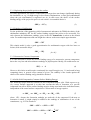
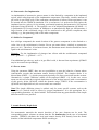
computer time for certain problems, it may be adequate to increase the cutoff energy of a
projectile according to the energy transfer to the target atoms, resulting in
EF proj =
(m
+ m t arg et )
2
proj
4 m proj m t arg et
SBE tmin
arg et
(1)
as, e.g., for gaseous projectiles which are not trapped in the target (see 4.)
Note! In general, it is not justified to identify the cutoff energies with the displacement
threshold energies (see 3.4) which are in the order of several 10 eV. This would reduce the
computing time significantly, but suppress all cascade development below these energies, and
thus, e.g., result in a drastic underestimation of sputtering.
3.2 Bulk Binding Energy
In a BCA simulation, the bulk binding energy, BE(I), is subtracted from the energy transfer to
the recoil atom before it is set in motion. A well-defined value for this energy is difficult to
obtain. Therefore, it is often simply set to zero, with good results, e.g., for sputtering yields if
other standard parameters as described here are chosen. It is also known from TRIM experience
that an increase of the bulk binding energies to up to a few eV requires a corresponding
decrease of the surface binding energies in order to obtain the same sputtering yields. It is
recommended to set the bulk binding energies to the default value of zero.
3.3 Surface Binding Energy
The surface binding energies determine critically the sputtering yields. Theoretically, the
sputtering yield is proportional to the inverse of the surface binding energy. In TRIDYN, the
effective surface binding energy of each target component can be chosen in dependence on the
actual surface composition. With cj denoting the surface atomic fractions of the target atoms j
(1#j#NCP, Σ cj = 1), the surface binding energy of a surface atom i is given by
SBE i =
NCP
∑ SBV
j=1
ij
⋅cj
(2)
with the matrix components SBVij . Eq. (2) includes the simple choice of surface binding
energies which are independent of the surface composition, by the default setting SBVij = SBEi
for all components j.
In the following, recipes of increasing complexity will be given for the choice of the surface
binding energies.
9
3.3.1 Neglecting the projectile species at the surface
For some applications, the surface composition of a target does not change significantly during
the simulation, as, e.g., for high-energy or low-fluence implantations, or inert gas bombardment
where the gas concentration is neglected (see 4.) In such cases, the choice of the surface
binding energy of the projectile species is not critical. A reasonable choice is
SBE proj = EF proj
(3)
3.3.2 Enthalpy of Sublimation
For the prediction of the sputtering yield of monoatomic substances by TRIM, the choice of the
sublimation enthalpies ∆Hs for the surface binding energies has proven to be successful. For
each element the sublimation enthalpy given in the file elements.dat is taken as the default
value. For multicomponent solids one might also choose as the most simple approximation
SBE i = ∆H is
(4)
This simple model is also a good approximation for multiatomic targets with low heats of
fusion, such as metallic alloys.
SBVij = ∆H is
for all j
(5)
3.3.3 Nonreactive Gaseous Components
It is often difficult to define the surface binding energy of a nonreactive gaseous component,
due to the very low and often unknown enthalpy of physisorption. Ideally, on would tend to set
s
∆H gas
→ 0
(6)
However, this choice would require consistently low cutoff energies (see 3.1) and result in long
computing times. A general recipe cannot be given. The stability of the results against the
choice of the surface binding energy should be checked.
3.3.4 Solid-Solid Compounds (Constant Surface Binding Energy)
The following recipes shall be restricted to two-component targets AnBm. With respect to eq.
(4), a more realistic approach is to take into account the heat of formation of a specific
compound, but still to define surface binding energies being associated to the individual atoms,
independent of the actual surface composition. Conservation of energy requires
n ⋅ SBE A + m ⋅ SBE B = n ⋅ ∆H As + m ⋅ ∆H Bs + ∆H
f
(7)
where ∆H f denotes the formation enthalpy per molecule of the compound. If the heat of
formation is small, it might simply be added to the enthalpy of sublimation of one of the
constituents, e.g., B. This results in
SBE A = SBV AA = SBV AB = ∆H As
SBE B = SBV BA = SBV BB
10
1
= ∆H + ∆H
m
s
B
(8)
f
This formalism may also be employed if ∆H f is large, but if the surface composition remains
far from the pure component B. Then, with eq. (8), the surface binding energy of the pure A
surface is approximately correct, and eq. (7) is fulfilled. Physically, this model is justified, if,
e.g., preferential sputtering or thin film deposition result in a surface composition between that
of the stoichiometric compound and an enrichment of the component A.
Example: Preferential sputtering of TaC by He at keV energies results in an enrichment of Ta at
the surface. Therefore, the choice of the surface binding energies should be good for the
compound itself and for the limit of a pure Ta surface. With ∆HsTa = 8.1 eV, ∆HsC = 7.41 eV, and
∆H fTaC = 1.54 eV, it is reasonable to set SBETa = SBVTaTa = SBVTaC = SBVTaHe = 8.1 eV, and SBEC =
SBVCTa = SBVCC = SBVCHe = 8.95 eV, and for the projectile component SBEHe = SBVHeTa = SBVHeC =
SBVHeHe = EFHe = 9 eV (see 3.3.1 and eq. (1)).
3.3.5 Solid-Gas Compounds (Constant Surface Binding Energy)
If one of the constituents of the target AnBm, e.g. B, is from a diatomic gas, its enthalpy of
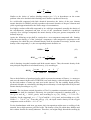
dissociation ∆Hdiss has to be taken into account. Then, in analogy to eq. (7)
n ⋅ SBE A + m ⋅ SBE B = n ⋅ ∆H As + ∆H f +
m
∆H diss
2
(9)
As the gaseous component will normally not be enriched significantly, a proper choice is
SBE A = SBV AA = SBV AB = ∆H As
SBE B = SBV BA = SBV BB
1
1
= ∆H f + ∆H diss
2
m
(10)
Example: During the ion beam synthesis of Si3N4 by nitrogen bombardment of silicon the
surface stoichiometry remains between pure Si and the stoichiometric Si3N4 compound. With
∆HsSi = 4.7 eV, ∆HdissN2 = 9.85 eV, and ∆H fSi3N4 = 7.8 eV, one obtains SBESi = SBVSiSi = SBVSiN =
4.7 eV, and SBEN = SBVNSi = SBVNN = 6.95 eV.
In some cases, an atomization enthalpy ∆Ha per atom of the gaseous component can be found in
the literature (see, e.g. ref. 5). Then
SBE B = SBV BA = SBV BB = ∆H Ba
(11)
This is strictly valid only if the deviation of the surface composition from stoichiometry is
small.
3.3.6 Solid-Solid Compounds (Variable Surface Binding Energy)
For a diatomic compound AnBm , eq. (2) reads
SBE A = SBV AA ⋅ c A + SBV AB ⋅ c B
SBE B = SBV AB ⋅ c A + SBVBB ⋅ c B
11
(12)
Physically, the matrix elements SBVij denote the interaction energies between atoms i and j.
Therefore, SBVij = SBVji has been assumed. For a solid-solid compound, they are related to the
enthalpies of formation and sublimation, ∆Hf and ∆Hs, respectively. For cA = 1 and cB = 0 and
vice versa, the pure components A or B are given, so that
SBV AA = ∆H As
(13)
SBV BB = ∆H Bs
The combination of eqs. (7,12,13) yields for the stoichiometric compound with cA = n/(n+m)
and cB = m/(n+m)
SBV AB = SBV BA =
(
)
n+m
1
∆H As + ∆H Bs +
∆H
2 nm
2
f
(14)
Compared to eq. (8), eqs. (13,14) are of better symmetry and thus more rigorous, but still only
valid if the deviation from the stoichiometric compound is not too strong. Alternatively, by
setting cA = 0 and cB = 1 in eq. (12 top) or vice versa in eq. (12 bottom), the non-diagonal
matrix elements may be identified with the sorption energy of A on the elemental B surface,
and vice versa, which are not symmetric in general. Then
sorp
SBV AB = ∆H AB
sorp
SBV BA = ∆H BA
(15)
where ∆Hsorpij denotes the sorption enthalpy of atom i on the elemental surface j.
Unfortunately, the sorption enthalpies are not readily available in literature, so one will
generally prefer the approach of eq. (14), except when treating specific problems of surface
physics.
3.3.7 Solid-Gas Compounds (Variable Surface Binding Energy)
If in a diatomic compound AnBm one of the components is from a diatomic gas, e.g., B, one may
neglect any interaction of B atoms in the surface. (Otherwise, they would react and form a
volatile molecule.) Therefore
SBV AA = ∆H As
SBVBB = 0
(16)
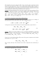
In analogy to 3.3.6, the combination of eqs. (9,12,15) yields for the stoichiometric compound
SBV AB = SBV BA =
n+m
n+m
1
∆H As +
∆H f +
∆H diss
4n
2 nm
2
12
(17)
In summary, the matrix formulation for the surface binding energies (eq. (2)) allows a large
variety of different models for the surface binding as discussed in 3.3.1-3.3.7. Similar
formalisms can be derived for more than two components. Other models might be appropriate
for specific problems.
3.4 Relocation Threshold Energy, Subthreshold Recoils
The relocation of recoils is steered by the recoil index IRC0 and the relocation threshold
energies ED(I). The relocation threshold critically determines the amount of ion mixing, but
also the shape of compositional profiles resulting from low-energy implantation and/or
preferential sputtering. The width of collisional mixing profiles scales as ED-1/2.
The conventional model assumes that a Frenkel pair can only be formed if the interstitial atom
is relocated far enough from its original lattice site, corresponding to a minimum energy
transfer when it is created. This minimum energy transfer is denoted as the displacement
threshold energy, which is in the order of several 10 eV. This model can be implemented by
identifying the relocation threshold energies with the displacement threshold energies, and
setting subthreshold recoils "bound" with IRC0>0. (In the simulation, this causes all recoil
atoms to be followed down to their cutoff energy, but to be restored at their original sites after
cutoff, provided their initial energy had been below the relocation threshold energy. In this way,
in the subthreshold regime only mass transport is suppressed, whereas cascade evolution and
momentum transport are maintained. Thus, e.g., sputtering is not influenced by the choice of
the relocation threshold.)
It should be noted that the concept of a displacement threshold is strictly valid only for a
perfect and nondamaged crystal. In an amorphous substance or in a solid being subjected to
high-fluence ion bombardment (which is the standard application of a TRIDYN simulation),
relocation thresholds might be significantly lower. Well-based data cannot be given. However,
according to experience with, ion mixing and preferential sputtering simulations and their
comparison to experimental findings, a relocation threshold energy of 8 eV has turned out to be
successful in a number of different systems, such as metallic compounds at low temperature
and oxides, so that this value is recommended.
For each element the relocation threshold energy given in the file elements.dat is taken as the
default value.
The "free" subthreshold recoil option (IRC0<0) gives additional flexibility. In this case, all
recoils remain at the position where the cutoff energy is reached. Thus, the cutoff energies (see
3.1) serve as effective relocation thresholds. Then, the displacement threshold energies can be
chosen independently, with corresponding results in the "static" output file (see below).
Note! With the "free" subthreshold recoil option (IRC0<0), make sure that sputtering is not
influenced by the choice of excessively high cutoff energies.
4. Maximum Concentration, Reemission, Simplified "Diffusion" Model
For each component, a maximum atomic fraction in the target can be defined by QUMAX(I).
This is of particular interest if gaseous species are involved.
13
4.1 Nonreactive Gas Implantation
An implantation of nonreactive gaseous atoms is often limited by a saturation in the implanted
region, which often depends on the implantation temperature. Physically, sizeable amounts of
gas reside in gas-filled voids. If the saturation concentration is known from experiment, it can
be inserted into the TRIDYN simulation. If it is not known, it is preferred to fully ignore the
implanted species (such as for ion mixing, preferential sputtering and nonreactive ion-assisted
deposition) using QUMAX = 0. The opposite case of an unlimited implantation (QUMAX = 1)
is problematic for several reasons: In addition to an unrealistically high gas incorporation, a
large fraction of the collisional energy will be transferred to the gaseous component, thus
reducing, e.g., the sputtering yields of the other components.
4.2 Solid-Gas Compound
In a solid-gas compound, the atomic fraction of the gaseous component is often limited to a
value close to the stoichiometric fraction. Excess gas atoms behave similarly to nonreactive
gases (see 4.1). Therefore, if not known better, the maximum atomic fraction should be chosen
equal to the stoichiometric value.
Example: For the implantation of nitrogen into silicon with the stoichiometric compound
Si3N4, QUMAXSi = 1, QUMAXN = 0.571.
If an additional gas take-up, such as in gas-filled voids, is known from experiment, QUMAX
may be increased correspondingly.
4.3 Excess Atoms
Using the parameter IDIFF, there are two possibilities to steer the behavior of atoms whose
concentration exceeds the maximum atomic fraction QUMAX. The simplest choice is to
discard them (IDIFF = 1), which corresponds physically to a direct reemission into the vacuum.
Alternatively, a simple "diffusion" model can be employed (IDIFF = 0). In this case, excess
atoms are moved from their original depth interval to the nearest interval with a concentration
of this species below QUMAX, within the dynamic range TTDYN. If the concentration is
QUMAX in all depth intervals, the excess atoms are reemitted.
Note! The simple diffusion picture is realistic only for some specific systems, such as the
formation of a buried oxide in silicon by oxygen implantation. It is not appropriate for a
corresponding formation of a buried nitride. This indicates that any generalization of the simple
diffusion model is not justified.
5. Atomic Density, Depth Scale
For monoatomic materials the atomic densities of the pure element can be used. The
corresponding atomic volumes are taken from the file elements.dat. In the case of compound
materials, TRIDYN calculates the local total atomic density DNS linearly from the atomic
densities of the individual components DNS0 according to
14
NCP
cj
1
=∑
DNS j = 1 DNS 0 j
(18)
Similar to the choice of surface binding energies (see 3.3), in dependence on the actual
problem it has to be decided which limiting cases shall be reproduced correctly.
In a solid-solid compound with little chemical interaction, the choice of the pure element
atomic densities for DNS0(I) trivially reproduces the atomic densities of the pure elements and
yields a good approximation for the whole range of concentrations.
In a highly covalent solid-solid compound or in a solid-gas compound, normally the density of
the stoichiometric compound and that of one of the constituents should be reproduced
correctly. (In a solid-gas compound, the atomic density of the pure gaseous component is illdefined, anyway.)
Again, the following recipe shall be restricted to a two-component compound AnBm. Starting
from the mass density ρA of the "principal" component A (the nongaseous component or the
component for which the pure elemental density shall be reproduced correctly), and the mass
density of the compound ρAnBm, the corresponding atomic densities are
DNS 0 A =
ρAL
MA
(19)
ρ AnBm L
nM A + mM B
(20)
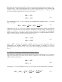
DNS AnBm = (n + m )
with L denoting Avogadro’s number and M the atomic masses. Then, the atomic density of the
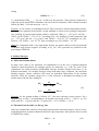
non-principal component is calculated from eq. (18) according to
n+m
1
n
1
−
DNS 0 B =
m DNS AnBm m DNS 0 A
−1
(21)
Due to the definition of pseudoprojectiles which represent increments of fluence, i.e. atoms per
unit area, the natural depth scale of TRIDYN is an areal density, with each depth interval given
by the total number of atoms per unit area in this interval. For the resulting depth profiles,
geometrical depths are calculated by dividing the areal density of each depth interval by its total
atomic density according to eq. (18).
Example: The ion-beam assisted deposition of Ta2O5 by tantalum evaporation and oxygen ion
bombardment shall be simulated. Obviously, the principal component is tantalum with ρTa =
16.6 g/cm3 and ΜTa = 180.95 g/mole, and according to eq. (19), DNS0Ta = 5.53A1022 cm-3.
Similarly, for the compound, ρTa2O5 = 7.5 g/cm3 and ΜO = 16.0 g/mole, and according to eq. (20),
DNS0Ta2O5 = 7.16A1022 cm-3. From this and eq. (21), the input atomic density for the oxygen
component results as DNS0O = 8.11A1022 cm-3.
For the bombardment with inert gas atoms, their incorporation might cause a swelling of the
material, due to high-pressure gas-filled voids. The density of the gas within these bubbles and
their volume fraction are mostly unknown. Therefore, one might simply discard the swelling by
15
setting
DNS 0 InertGas → ∞
(22)
i.e., numerically DNS0InertGas > 1028 cm-3. In this way, the presence of the gaseous component is
neglected for the depth scale calculation, but not for the development of the collision cascades
(unless QUMAX = 0 for the inert gas – see 4.)
Example: A TaC surface is bombarded with He. Due to the more efficient momentum transfer,
carbon will be sputtered preferentially, so that tantalum is chosen as the principal component.
Any swelling by incorporated helium shall be neglected. With ρTa = 16.6 g/cm3 and ΜTa =
180.95 g/mole, DNS0Ta = 5.53A1022 cm-3 according to eq. (19). Similarly, for the compound, with
ρTaC = 13.9 g/cm3 and ΜC = 12.0 g/mole, and, DNS0TaC = 8.68A1022 cm-3 according to eq. (20).
From eq. (21), DNS0C = 2.02A1023 cm-3 and, according to eq. (22), DNS0He = 1030 cm-3.
Note! For compounds with a very high atomic density, the atomic density of the non-principal
component may become negative according to eq. (21). This represents no problem for the
processing in TRIDYN.
6. Incident Energies
6.1 Molecular Bombardment
In many cases, such as for molecular ion implantation or in the case of plasma-enhanced
chemical vapour deposition, the incident species are molecules, e.g., AnBm. For each of the
constituents, the beam fractions QUBEAM(I) and the incident energies E0(I) have to be
defined consistently. For incident energies being sufficiently large compared the molecular
binding energies, surface collisions will cause an immediate dissociation of the incident
molecule. Then, the incident energy E0AnBm of the molecule is distributed according to the
atomic masses ΜA and ΜB, resulting in
E0A =
MA
⋅ E 0 AnBm
nM A + mM B
MB
E0B =
⋅ E 0 AnBm
nM A + mM B
(23)
Example: For the plasma etching of silicon, CF3+ ions may represent a major species. For a
substrate bias of 500 V corresponding to an incident ion energy of E0CF3 = 500 eV, eq. (23)
yields with ΜC = 12 g/mole and ΜF = 19 g/mole E0C = 87 eV and E0F = 138 eV.
6.2 Thermal Neutrals and Low-Energy Ions
Often, the incident flux consists of ions and neutral particles at thermal energies, such as in ionassisted deposition or plasma-enhanced chemical vapor deposition. Such species can be treated
in TRIDYN by setting
E 0 neutr = 0
16
(24)
As stated above, the treatment of the collisional processes in TRIDYN is problematic for very
low ion energies (about 30 eV and below). Nevertheless, the low-energy incident particles will
be correctly deposited at the surface.
The user should be aware of the fact that each incident pseudoparticle is accelerated by the
surface binding energy SBE(I) before entering the solid.
17
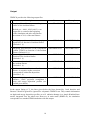
Output
TRIDYN provides the following output files:
#
Description
Name
Example
namePRxx.DAT
AlN5PR04.DAT
2 Surface composition (within the averaging
depth DSF) as function of incident fluence
(Default cf. 1))
nameSRFC.DAT
AlN5SRFC.DAT
3 Integrated areal densities of the components
(within TTDYN) as function of the incident
fluence (Default cf. 1))
4 Sputtering yields of the components as
function of the incident fluence
(Default cf. 1))
nameARDN.DAT
AlN5ARDN.DAT
nameSPYL.DAT
AlN5SPYL.DAT
5 Accumulated reemitted fluence as function of
the incident fluence
(Default cf. 1))
nameREEM.DAT
AlN5REEM.DAT
6 Surface recession as function of incident
fluence. A negative surface recession
corresponds to a thin film deposition
(Default cf. 1))
nameSRRS.DAT
AlN5SRRS.DAT
7 Output listing (input data, statistics, particle
balances, "static" projectile (component 1
only) and energy deposition profiles (see
remark given below)
nameOUT.DAT
AlN5OUT6.DAT
1 Depth profiles of the components for given
values of the incident fluence.
Default: xx = 00,01, 02,03,04,05, i.e.an
output file is created at the beginning
of the simulation and after each fluence
increment of 20 % of the total fluence
In the output listing (# 7), the lines given below the lines denoted by "areal densities and
fluences" should in general be ignored for a dynamic TRIDYN run. They contain information
on depth and energy deposition profiles as well radiation damage in a simple Kinchin-Pease
model, integrated over the whole run. However, in static mode (IDREL<0), the simulation
corresponds to a standard TRIM simulation with this output.
18
Test of the statistical quality and precision of the results using the parameter MAXCHA
The output listing (file nameOUT.DAT) contains the parameter MAXCHA. For results with
sufficient statistical quality and precision MAXCHA should be less than 0.05! An increase
of the number of pseudoparticles NH and a reduction of the total fluence FLC result in a
decrease of MAXCHA.
Error messages
During the simulation the error messages are written on the screen and into the output listing
(file nameOUT.DAT) if certain program parameters were not chosen properly. Some of the
errors can stop the program before the regular end of simulation. The following error messages
may occur:
1) ”Projectile (recoils) range exceeds dynamic composition range. Increase TTDYN”
This message appears when the projectile or a recoil went out of the limit of dynamic
composition range. The simulation is stopped after the accumulation of a definite number
(default: 5 % of the number of projectiles) of such events. The depth of dynamic simulation
should be increased to avoid this problem.
2) ”Depth interval completely depleted. Decrease FLC or increase NH”
This message appears if the change of the composition induced by a projectile in a certain
depth interval is so high, that the interval is completely depleted. The simulation is stopped
after accumulation of a definite number (default: 1 % of the number of projectiles) of such
events. The problem can be avoided by decreasing of total fluence or by increasing the number
of ion histories (pseudoprojectiles).
3) ”Deposited depth is larger than dynamic depth range. Output profile might be in error.
Increase TTDYN (and NQX)”
Decrease the total fluence or increase the depth for dynamic simulation (and number of
intervals if the same depth interval is required) to avoid this problem.
4) ”Recoil storage capacity exceeded”
The total number of recoils for each projectile is limited by a definite number (default: 20000).
If this limit is exceeded (this occurs only for very high ion energies) the program is stopped.
19
References
1. W.Möller and W.Eckstein, Nucl. Instr. and Meth. in Phys. Res. B 2 (1984) 814.
2. W.Möller, W.Eckstein and J.P.Biersack, Comput. Phys. Commun. 51 (1988) 355.
3. W.Möller and W.Eckstein, Report IPP 9/64, Max-Planck Institute of Plasma Physics,
Garching (1988)
4. W.Eckstein and J.P.Biersack, Appl. Phys. A 37 (1985) 95.
5. R. Kelly, Surf. Science 100 (1980) 85.
20