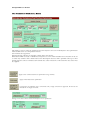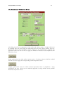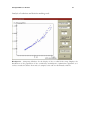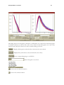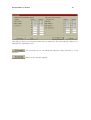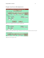
1
USER’S MANUAL Email: mailto:[email protected] Web: http://www.mlahanas.de WinOpt-HDR User Manual 2 Information in this document is subject to change without notice. This User’s Manual can be reproduced, stored in a retrieval system, or transmitted in any form or by any means electronic or mechanical, including photocopying and recording for any purpose. The following trade names are referenced throughout this manual: Windows NT, Windows 2000, Windows 95/98 are trademarks of Microsoft Corporation. Pentium, Pentium II, Pentium III and Pentium V are trademarks of Intel Corp. WinOpt-HDR User Manual 3 Introduction ...................................................................................................................8 Dose computation using dosimetric Look-Up Tables ....................................13 Sampling Points..............................................................................................................14 Optimized bounding boxes .....................................................................................16 Triangulation and Collision detection .................................................................17 Dose Optimization in HDR brachytherapy ..........................................................................18 Dose optimization using variances .......................................................................18 Dose optimization using dose-volume histogram based objectives ............21 Single objective weighted sum optimization ......................................................23 True multiobjective optimization ..........................................................................24 M ultiobjective optimization. ...............................................................................25 Introduction and Definitions ..................................................................................25 Solutions obtained with the use of weighted sums in optimization procedures .......27 Generation of uniform and random importance factors for multiobjective optimization ................................................................................................................28 Decision making tools ............................................................................................29 Template based Inverse Planning ....................................................................31 Post Implant Optimization ..................................................................................33 The User Interface ....................................................................................................34 The FILE I/O Dialog .............................................................................................36 The Dose Parameter Dialog....................................................................................37 The Template based Inverse Planning Dialog ..................................................40 Template View ............................................................................................................48 The Optimization Dialog.........................................................................................52 Post Plan Optimization...............................................................................................53 Template based inverse Plan Optimization ....................................................71 The Dose distribution Dialog .................................................................................72 Examples of using WinOpt-HDR ....................................................................80 PTV based optimization method....................................................................................80 DVH based multiobjective optimization method. .........................................................83 Example of template based manual Inverse Planning ..........................86 WinOpt-H DR Errors and Warnings ...............................................................94 General References ...................................................................................................96 WinOpt-HDR User Manual WinOpt-H DR References 4 ....................................................................................98 APPENDIX ............................................................................................................... 100 1. Template Coordinate System............................................................................ 100 2. The VOI Charisma File ..................................................................................... 101 3. The Catheters Charisma File ............................................................................ 109 4. The Loading Charisma File ............................................................................. 112 The WinOpt-HDR Log File............................................................................................... 115 The WinOpt-HDR Solutions File ...................................................................................... 120 WinOpt-HDR User Manual 5 WinOpt-HDR Overview and Tutorial WinOpt-HDR is a software toolkit designed for anatomy based dose optimization for high dose rate (HDR) brachytherapy. Its algorithm are continuously updated and improved. It has been developed by Michael Lahanas in cooperation with Dimos Baltas head of the Medical Physics & Engineering department of Klinikum Offenbach in Germany. Kostas Karouzakis and Stavroula Giannouli from the National Technical University of Athens helped in the development of parts of the WinOpt-HDR source code. Additional studies by Natasa Milickovic and Maria Papagiannopoulou were important in estimating the performance of various algorithms. Some of the methods, which are unique in HDR brachytherapy, have been described in numerous publications in medical physics journals and in conference proceedings. WinOpt-HDR is a demonstration toolkit for our solution which we offer for the true multiobjective dose optimization problem in HDR brachytherapy. It does not include other tools such as catheter reconstruction, volumetric rendering, image fusion etc. It assumes that these possibilities exist in some other program and that the information can be exported so that they can be used by WinOpt-HDR. The methods presented in this program should be easily ported to any brachytherapy treatment planning system. WinOpt-HDR includes the necessary tools for data mining, analysis and optimization with respect to multiple objectives. WinOpt-HDR has been found in comparison to Nucletrons planning system PLATO to produce superior and in the worst case compatible results. Systems like PLATO provide only a single solution and/or organs at risk cannot be considered except manually and if only using some phenomenological approximations. WinOpt-HDR offers the possibility to provide in principle all possible solutions. It offers the planner the tools to select the best solutions out of this set. Plato and other systems often use artificial methods to reduce negative dwell position weights. These methods include constraints on the objective function which reduces but does not eliminate these solutions. An artificial correction mechanism is applied by setting all negative dwell times equal to 0. This mechanism necessarily reduces the quality of the obtained solution. WinOpt-HDR avoids the generation of such non-physical solutions. It does not require any artificial constraint for the objective method and also no correction at any stage of the optimization process. The tasks should perform in the following order: 1. 2. 3. 4. Preparation and input of data for the optimization. Selection of a optimization method. Selection of a solution. Analysis of the results. It is assumed that the final acquired anatomy, definition of PTV and critical structures contours , with the needles in situ (CT or 3D-U/S) reconstructed [17], [18]. Additional the source dwell positions to be considered in the optimization are selected. Thereafter the anatomy based optimization tool as described previously can be utilized for the case of HDR brachytherapy for defining the exact source dwell times and source dwell positions within the implanted catheters, that will result to the desired 3D dose distribution (user objectives). The parameters needed to drive the afterloader in order to deliver the planned brachytherapy are then calculated and stored. WinOpt-HDR User Manual 6 It is assumed that the geometry of the VOIs, the catheter geometry and the source dwell positions and the dwell times or loading is written in a special format, see Appendix 2 and 3. Minimum System Requirements WinOpt-HDR version 2.0 runs on a standard PC hardware platform with the operating system Windows 95/98, Windows NT or Windows 2000. Dosimetric fast calculation requires the use of large look-up tables. A RAM of 256 MB and more is therefore recommended. A graphic-card that supports OPENGL is recommended but not necessary. Current version supports only implants which include in addition to the surrounding normal tissue maximal three critical structures. Version 2.0 is not full optimized. A speed-up of optimization and dose calculation by a factor of 2-3 is possible. The computation time increases linear with the number of active source dwell positions. New dose calculation methods could decrease the computation time by an additional factor of 2-5. WinOpt-HDR requires that in the registry a directory is specified such as in this example: [HKEY_LOCAL_MACHINE\SOFTWARE\Winopt-HDR] "Directory"="d:\winopt" This directory is expected to exist and that WinOpt-HDR is able to create files in this directory. The user should modify the path which is this example is set arbitrary to d:\winopt! WinOpt-HDR User Manual Definition of Terms OAR O CT C DVH D HDR H LDR L ow Dose R ate PTV P lanning T arget Volume PC P ersonal Computer U/S U VOI V rgan At R isk omputed T omography ose Volume H istogram igh Dose R ate ltra Sound olume Of Interest 7 WinOpt-HDR User Manual 8 Introduction In brachytherapy small-miniaturized radioactive sources are positioned within the tumor so that an effective dose delivery results while saving healthy tissues. This can be done by two principal methods: • The sources can be positioned directly into the tumor tissue and will stay there until the end of their life (continuously decreasing activity of the sources according to their decay scheme and decay half-time). This is called permanent implantation and for this technique low activity and low energy radioactive sources, radioactive seeds , are used. This method is call LDR method. • A single radioactive source of high activity driven and controlled by a computer system is stepping within hollow catheters, which have been previously implanted into the tumor, according to pre-designed chart: specific dwell time for a specific dwell position within a specific catheter. The treatment time for such a temporary implantation is very short. Due to the high activity of the used single stepping source (Iridium-192 nuclide) this method is called H DR . We consider here only the HDR case. Clinicians need to know before starting inserting catheters/needles into the tumor, how many catheters are needed and what is their ideal position into the tumor. The step described above for defining the appropriate geometry, number and location of needles within the tumor in order to achieve the desired therapeutic effect is called pre-planning. We have a post implantation dose optimization problem, or post-planning problem, i.e. given the position of the source dwell positions to determine the dwell times such that the resulting dose distribution satisfies to the maximum possible extent the objectives of conformal HDR brachytherapy. Conformal anatomy based dose optimization considers the dose in the planning target volume, PTV, and critical structures, including the surrounding normal tissue. Goals of the conformal anatomy based dose optimization is the complete coverage of the PTV with a dose at least equal to the prescription dose and simultaneously to avoid dose values above some critical value, specific for each critical structure in the surrounding normal tissue and in critical structures, inside or in the neighborhood of the target. An additional objective is the avoidance of dose values much above the prescription dose in the target. With anatomy based optimization we also mean that user can define his target for the tumor and the dosimetric limitations to the critical structures. For example for the case of prostate this could be: deliver at least 7.0 Gy to the prostate gland where doses of 10.5 Gy have to be avoided to the urethra and dose of 10 Gy have to be avoided to the rectum. Since these objectives are usually controversial, the optimization system has to offer following tools: 1. User can define his own (pre-known) significance factors of the objectives 2. User can define several combinations of these significance factors 3. The system is able to estimate the feasible spectrum of solutions among which the user has to make his decision. WinOpt-HDR User Manual 9 Tools 1 and 2 have to be fast enough so that the results can be evaluated and used for the interactive steps. Step 3 should be utilized for finally optimizing the implant dosimetry. Fig. 1. A single cylindrical shaped radioactive source of high activity (e.g. 192Ir) driven and controlled by a computer system is stepping within hollow catheters, which have been previously implanted into the tumor. The dose is calculated at a small number of points (sampling points). The contribution to the dose at each such point depends on the source dwell time, the distance and the angle θ. Today the majority of treatment planning systems in brachytherapy such as Nucletrons PLATO system use phenomenological optimization methods such as geometrical optimization. Additionally most of the algorithms used have the so called artificial problem of negative times which in principle does not exist and artificial methods such as setting the negative dwell times equal to zero and applying a dose renormalization are therefore used. 20%-50% of the dwell times that are always negative as a result of the optimization are arbitrarily set equal to 0. Dose normalization is then applied to rescale the dose at a specified number of dose points. Another method used is to introduce constraints on the objective function such as gradient constraints between dwell times of adjacent dwells, which reduces but does not completely avoids negative solutions. Still up to 20% of the dwell times can be negative. There is no reason WinOpt-HDR User Manual 10 why a gradient-based restriction should be applied to the objective function only to reduce negative times which can be avoided by a more natural and extremely simple method without imposing any restriction on the optimization result. Other approaches use a constraint of positive dwell times. They do not require some rather arbitrary modification of the objective function. This in principle increases the number of optimization parameters by a factor of two. If the constraints are satisfied only partial and negative dwell times are still present in the final solution again a correction mechanism must be applied. An additional constraint applied on the optimization result is the use of a dose point normalization based on the dose of some points for example on the minimum peripheral dose, or the average dose on the PTV surface. This is because the definition of what conformal brachytherapy means is not mathematical well defined. If the most important objective is to have a dose at least above some value in the entire PTV then a normalization based on the minimum peripheral dose can be used. By using this normalization method it is true that the dose in the PTV will be everywhere high enough but how is then the dose distribution in the surrounding tissue and in organs at risk? This method based on the normalization on a single point usually increases the dose in the surrounding tissue by in principle expanding the reference isodose so that it passes through this dose point at which the minimum dose was measured and if the point is on the PTV surface. If the dose is normalized using the PTV dose average value then we cannot have always high enough dose values anywhere in the PTV. As long as there are no sources outside the PTV it will more or less help us to avoid high dose values in the surrounding tissue. Also we have not full control of the dose in the organs at risk. This method assumes that the reference isodose can actually have the shape of the PTV. As the shape of the PTV is usually complicated and isodose surfaces are less complex it requires that the number of sources is large and adequately distributed in the PTV. A method that is less restricted is the normalization free method. In this method there is in principle no point defined at which the dose is normalized. The optimization is free so that finally we have the best possible results. Currently there are some requirements to document the dose in a definite way and the established methods introduce constraints that reduce the quality of the dose distribution which can be obtained. It is still not clear that the problem is not a single objective problem but a multiobjective problem with contradictory and competing objectives that requires the determination of at least a portion of the Pareto front. Today when there are no exact established quality criteria the planner cannot guide the system exactly to a single solution on the Pareto front. The problem is transformed into a single objective problem using arbitrary importance factors for each objective and combining the objectives into a single objective function to be minimized. What does it mean to use an importance factor 0.9 for objective 1 and 0.1 for objective 2? That the objective 1 is more or less 9 times more important than objective 2? If there is a strong tradeoff then a combination of 0.89 and 0.11 can give quite different results! Some algorithms require importance factors of 20000 for one objective and 10 for another which shows that also the optimal importance factors depend on the objective function used. In IMRT we have found that the surrounding tissue and PTV coverage objective produce not the best results with a 0.1 and 0.9 importance factor respectively as assumed but sometimes the best result was obtained with importance factors 0.7 and 0.3 or 0.3 and 0.7 respectively. This is because some objectives are cooperating to some extent and to some extent they are competing, depending on the importance factors of the other objectives and in a complicated way which depends on the WinOpt-HDR User Manual 11 topology of the PTV and the OARs, the beam orientation etc. It is not very much different in brachytherapy. Not only the optimization method is important but also the distribution of sampling points used in the optimization procedure. One problem is that dose variances are calculated from sampling points limited on the contours which even if their number is large it is not true that the variances are approximated with sufficient accuracy. Another problem is the use of points inside catheters. Optimization is the most important part of a treatment planning system and to a smaller extent for example its volume rendering capabilities. It seems therefore strange that these constraints used in the optimization, models based on crude approximations are still used in the majority of planning systems. It is true that speed is an important factor. Nevertheless also methods such a geometric optimization although may be fast require from the planners often to manually intervene in order to modify the dwell times if the results are not satisfactorily. Using only a very small set of importance factors, 1-2 usually, the planner is left without information of what actually is possible. The true multiobjective optimization is free of importance factors. Even if a set of importance factors which somehow gives reasonable results can be found for some fixed topology it requires time to find these and a significant time has to be spent. A multiobjective algorithm does not require such training. Sometimes although it seems strange in principle it is easier to calculate all possible solutions at once than only one particular. This is true for true multiobjective optimization algorithms. In a single objective optimization there is only a single decision, accept the solution or not. If not a new solution must be calculated or a manual manipulation of dwell times or dose rescaling remains which takes a lot of time, usually much more than the automatic optimization. These are definitive not methods of the 21st century. Today the computing power of modern PCs allows the determination of hundreds of possible solutions. The planner now has information that was to him/her not available before or only to a very limited extent. The optimization problem is not an optimization problem anymore that has to consider arbitrary importance factors, arbitrary correction methods and objectives based on nomograms or other hand waving arguments, but is now transformed to a decision making problem. The planner is confronted with all possible solutions and information. He/She knows now all the answers to the questions: What is possible if I modify the importance factors? What coverage can I get? How this affects the dose value in the organs at risk? Even if some new systems give an approximate answer to some of these questions these methods use a sometimes-complicated way to obtain part of this information. A true multiobjective method requires a set of objectives functions that are more intuitive for the planner than variances of dose distributions. The most natural way from a dosimetric-based approach seems to be the use of dose-volume histogram based objectives. Methods have been proposed which try to optimize the importance factors using an optimization method. The objective function for a set of importance factors is calculated and then a different set of functions combined with another set of new importance factors is used to establish a quality criterion of the optimization results. Here the problem has been bypassed by the introduction of a new set of artificial importance factors, but this method is probably better than using a fixed set of arbitrary importance factors for the objective functions. WinOpt-HDR User Manual 12 It is clear that methods such as the geometric optimization method have been established through the years The hope is that the new optimization methods slowly will be introduced in new planning systems and the planners will get familiar with the new methods. It requires some training but the result will be less arbitrary without unnecessary correction methods, less manual intervention. It will also produce better optimization results. Finally it will produce probably new quality criteria that at the moment are not very well established. It is true that we cannot expect miracles from any optimization method since the number of sources, and their distribution finally introduces physical restrictions of what is possible. Aim of a true multiobjective anatomy dose optimization is to show these limitations independent on arbitrary corrections and importance factors. It is also necessary not to use the word inverse planning for only post plan optimization, since inverse planning means actually to find not only the dwell times of the optimal solution but also the optimal distribution of sources in space in an economic way, i.e. finding the smallest possible number of source dwell positions without significantly reducing also the optimization quality in comparison to a solution a very large number (within realistic limits) of sources. It should become clear soon or later that only multiobjective optimization should be used for the inverse planning problem. The new optimization methods do not require normalization on some arbitrary set of dose points. They do not require arbitrary correction mechanisms. They do not require arbitrary importance factors. All these constraints in the past have due to ignorance or due to limiting computational possibilities introduced restrictions on the optimization result. The dominance of the market by a single provider for treatment planning systems in brachytherapy has helped to establish the old methods and it is now difficult to replace these by the new methods. It is true that the new optimization methods require a slightly more complex cooperation with planners and still the decision making process of these multiobjective methods can be improved with some additional tools. A dose optimization procedure which does not require any human decision making process is difficult if not impossible to be realized. WinOpt-HDR User Manual 13 Dose computation using dosimetric Look-Up Tables The dose D(r) at r=(x, y, z) is conventionally calculated using Eq. (1). Ns Ns i =1 i =1 D (r j ) = ∑ si f (r j − ri ) = ∑ si f ij (1) In Eq. (1) ri is the position of the ith source and Ns the total number of sources. f(r-ri) is the dosimetric kernel describing the dose rate per unit source strength at r from a source positioned at ri. si is proportional to the air kerma strength Sk of the source. For the case of HDR afterloader si is equal to Sk·ti, where ti is the dwell time of the ith source dwell position and Sk is the air kerma strength of the single stepping source. We use dose calculation point Look-Up tables (LUT) in which the kernel values fij for each dose calculation point and source dwell position pair is calculated and stored in the table once in a preprocessing step. If we ignore the preprocessing time then the calcucation time for dose distributions is independent of the form of the dosimetric kernel. This enables us to use realistic kernels obtained by sophisticated Monte Carlo simulation routines [11]. The calculation requires only a file which contains the dosimetric LUT. The dose distribution around a cylindrical source is not isotropic due to the attenuation of the photons in the active source material, the encapsulation material, the source drive cable etc. Due to the cylindrical rotational symmetry the dose rate in a uniform isotropic medium is a function of r and θ only. The orientation of the source is determined from the catheter geometry. At each source dwell position a vector is calculated which is parallel to the cylindrical source axis and in opposite direction to the source drive cable, see Fig. 2. Fig. 2: Source dwell positions for a prostate implant. The white points are active source dwell positions, i.e. are considered in the optimization process, while blue points show inactive source dwell positions, rejected by the auto-activation algorithm. A tangent vector at each source dwell position is shown which defines the direction of the cylindrical source and which is used for the dose calculation. WinOpt-HDR User Manual 14 Sampling Points We estimate the dose distribution inside the PTV, critical structures and the PTV surface from the dose of a small number of points (sampling points). Fig. 3: Sampling points distributed on the contours and on the triangulated surface. For the contour based method no points are on both ends of the PTV. Therefore a large part of the surface is undefined for the optimization algorithm and the resulting isodose is bounded only by the PTV contours. Sampling points in the volume are generated from low discrepancy sequences or quasi-random distributed sampling points. In contrast to pseudo-random distributed sampling points voids and cluster are avoided. Monte-Carlo generated quantities convergence much more rapidly than a conventional pseudo-random sequence. We exclude sampling points inside catheters. This reduces the influence of very large dose values of sampling points that occasionally are produced very close to the source dwell positions. Statistical values obtained from the sampling points are calculated therefore with a higher accuracy [9]. Fig. 4: A catheter is defined by catheter describing points. These points are connected with cylinders and at each catheter describing point an additional sphere is included. The set of catheters cylinders and spheres are used to describe the geometry of a catheter that may be either metallic linear or plastic and curved. WinOpt-HDR User Manual 15 Fig. 5: The set of all catheters defined by the catheter describing points and extended by the catheter radius defines the bounding box of all catheters. The orientation of this bounding box is optimized such that its volume is minimum. Only sampling points in this optimal oriented box are tested if they are inside the catheters. WinOpt-HDR excludes the volume of parts of catheters and of parts of OARs which are inside the PTV. Such a case we have for example in a prostate implant where the volume of the urethra and the catheters inside the prostate is ignored and not included in the prostate volume. WinOpt-HDR User Manual 16 Optimized bounding boxes Our anatomy based optimization method uses optimal oriented bounding boxes [10] for a variety of reasons. For the efficient calculation of dose-volume histograms (DVHs) of anatomical structures obtained from sampling points inside the three-dimensional triangulated objects using the test routines described by Lahanas et al. [9] The sampling points are required to be outside catheters and critical structures but inside the object. The generation time of sampling points can be reduced significantly using optimal oriented bounding boxes of the object, the critical structures and catheters. For an optimal orientation of dose calculation grids for fast Fourier transform (FFT) based dose calculation methods [8], the number of grid points inside an object have to be maximized. If the axes of the grid are given by the axes of the minimum bounding box of the object then the number of grid points inside an object is maximal and this significantly increases the efficiency and accuracy of this method. For the efficient determination of the volumes of objects that take into account catheters, a simple hit or miss Monte Carlo method with a large number of random points (> 105) inside the bounding box of each structure (e.g. organs) is produced. The ratio of the number of points inside the structure to the number of points inside the associated bounding box, which is maximal for minimum bounding boxes, is equal to the ratio of the structure volume to the bounding box volume. From the known bounding box volume, the volume of the structure is then calculated. For the efficient calculation of DVHs of critical structures and the PTV a stratified sampling technique can be used [7] in which the regions also known as strata are defined by either optimal oriented bounding boxes or minimum enclosing spheres. Fig. 6. Contours of a critical structure (myelon) and the catheters of an implant showing the original bounding box (white) and the optimized bounding box (red). WinOpt-HDR User Manual 17 Triangulation and Collision detection Anatomy based optimization assumes that the geometry of the PTV and the OARs is given. WinOpt-HDR assumes that the VOIS are given in form of contours defined by points on the constours obtained from parallel image slices from CT, ultrasound or other imaging modalities. We apply a triangulation of these points for the reconstruction of their surface. This triangulation defines the geometry of the VOIS and is used for the calculation of the volume of the VOIS, excluding parts of OARs in these VOIS, such as the urethra inside the prostate case. During the manual semiautomatic or automatic segmentation there may be some overlap of VOIS. We apply a collision detection algorithm and report all triangles of all combination of VOIS which are in contact or if they intersect. WinOpt-HDR reconstructs the surface of the PTV, Body and OARs by a triangulation. VOIs with branches are not supported. WinOpt-HDR uses the triangulation algorithm of Fuchs et al. to reconstruct the surface of the VOIS from the points on the parallel slices. WinOpt-HDR User Manual 18 Dose Optimization in HDR brachytherapy Dose optimization using variances One solution of conformal HDR brachytherapy is to obtain a dose distribution such that the isodose of the prescription dose coincides with the PTV surface. In principle with this approach the use of an additional objective for the surrounding body is not necessary. This objective can be expressed as the problem to determine the time of the source dwells such that the resulting dose variance f S of the sampling points (dose points) uniformly distributed on the PTV surface is as small as possible. In order to avoid excessive high dose values inside the PTV we require a small as possible dose distribution variance fV inside the PTV. Due to the source characteristics these two objectives are competing. We use normalized variances for the two objectives: fS = 1 2 mS N S Ns ∑ (D − m ) , 2 i i =1 S fV = 1 2 mV NV NV ∑ (D j − mV )2 j =1 Where mS and mV is the average dose value on the PTV surface and in the PTV volume and NS, NV the corresponding number of sampling points. For these objectives the Pareto tradeoff surface (described later in the text) is convex and gradient-based algorithms converge to the global Pareto front. [13],[15]. In the past dose points have been use limited on the target contours. With this approach increasing the number of sampling points does not increase the coverage of the PTV. We developed a method to uniformly distribute sampling points on the whole PTV surface. This method requires the triangulation of the entire PTV surface. Based on the stochastic universal sampling method uniform distributed sampling points are generated on the PTV surface, see [9]. In the past treatment planning systems using dose point based optimization methods had to consider the problem of negative dwell times. Many phenomenological approaches have been used to eliminate, reduce or correct negative dwell times either at each optimization step or at the end of the optimization. One method specifies constraints such as the difference of dwell times between closely situated sources [4], [14]. Therefore the objective function is extended including a term that considers the gradient of dwell times (differences between neighbor sources). Since all algorithms use importance factors some empirical importance factor has to be used for this additional objective. This approach includes the additional objective like a penalty function that tries to reduce the number and the magnitude of negative dwell times. It does not eliminate such solutions and finally always a correction method is necessary. This method just sets all negative dwell times equal to 0 and renormalizes the dwell times after this correction. This method has the following problems: It includes an additional objective function that tries to reduce or eliminate negative source dwell times. This approach reduces the quality of the solutions since it introduces some constraint on the solutions such as the difference of source dwell times between two neighbor sources. Additional it requires an importance factor, which cannot be unique, and the influence on the result of it is case dependent. Another problem is that it finally cannot avoid negative source dwell times and therefore it has to correct the solution with the non-physical negative dwell times by setting these equal to 0. This further reduces the quality of the obtained solution. WinOpt-HDR User Manual 19 Other approaches use a constraint of positive dwell times. They do not require some rather arbitrary additional objective function. This in principle increases the number of optimization parameters by a factor of two. If the constraints are satisfied only partial and negative dwell times are present in the final solution again a correction mechanism must be applied. In order to eliminate this problem we use a simple mapping technique that transforms the linear constrained problem into a quadratic non-constrained problem. With this approach negative solutions are avoided. No constraints or bounds are applied in the search space. Therefore the method does not introduce any bias to the search algorithm. No additional objective functions, constraints, correction or importance factors are required. If organs at risk close or in the target except the surrounding normal tissue don’t ned to be considered then the powerful gradient optimization method converges according to the KuhnTucker theorem for convex or quasi-convex functions to a global solution. No local minima are present. The gradients guide the algorithm fast to the global minimum defined by a minimum variance on the PTV surface. In this approach the objective function f is scale invariant i.e. if the source dwell times are t1, t2, …, tN then f(t1, t2, …, tN) = f(at1, at2, …, atN), where a is any positive (a>0) number. A benefit of this method is that the search space can limited to any range such as [0, 1]. For other objective functions that are not scale invariant an absolute scale must be given. The optimization method requires that only source dwell positions inside the target should be used. If source dwell positions outside the PTV are included, then high dose values outside the PTV may exist. It is therefore necessary to use the auto-activation algorithm. The objectives in terms of variances allow the use of gradient-based algorithms that converge very fast to the global minimum. A single optimization requires only a few seconds. Fig. 7: Example of an optimization for the variance based method. The PTV, catheters and source dwell positions are show. Points on the PTV surface are included at which the dose variance around the prescription should be minimized. The result is show as the isodose surface of the prescription dose. WinOpt-HDR User Manual 20 The gradient-based deterministic algorithm can be extended to include dose variances for OARS. In this case it is possible that the algorithm is trapped by local minima. f OARi = 1 / N OARi Θ( D − DOARi )( D − DOARi ) 2 Where Θ(x) is the theta step function, N OARi is the number of sampling points in the ith OAR and DOARi is the critical dose for the ith OAR, i.e. only dose values above the critical dose value for each OAR are considered in the objective function. A fast simulated annealing algorithm is less sensitive to local minima and therefore is implemented in WinOpt-HDR. WinOpt-HDR User Manual 21 Dose optimization using dose-volume histogram based objectives In the past optimization methods were based on the dose of some sampling points at some special positions, such as on the PTV contours or basal dose points. The normalization of the dose was based on the values of these points. For the dose points on the PTV contours for example the mean dose value was normalized to the prescription dose. An optimization goal is the minimization of the variance. For a solution with a very small dose variance the isodose of the prescription dose then coincides with a high degree with the PTV surface. This normalization although imposes a constraint on the dose distributions and therefore to the obtained solution(s). If the PTV surface is complex it is impossible that the entire PTV receives a dose equal or larger than the prescription dose. The normalization at specific points introduces a constraint that produces practical always points in the PTV with dose values below the prescription dose (cold spots). Also it cannot consider critical structures inside the PTV or in its vicinity. In order to avoid to some extend under dosage or dose values above the critical dose in the critical structure it is necessary to rescale the dwell times of the obtained solution, i.e. to use some other normalization factor. This problem is always present more or less since it is impossible to satisfy all conflicting objectives simultaneously. It is a consequence of the limited number of sources. Additional the source characteristics are such that the possibilities of the obtained dose distribution are limited. In some cases the planner is willing to sacrifice then overdose of a portion of a region at risk in order to improve the probability of curing the disease. Constraints could be no more than x% of this region can exceed a dose value of Dcrit. One advantage of these so-called partial volume constraints is that the results in terms of objective values are more intuitive to understand. We used the following set of objectives formulated as partial volume constraints: 1) Fraction of PTV (including surface) with D< DVL 2) Fraction of PTV (including surface) with D> DVH 3) Average squared dose in the surrounding normal tissue: <DSBH2> 4) Fraction of CS with D> DCSCrit. DVL is the prescription dose, or lower dose limit and DVH is the high dose limit in the PTV. <DSBH2> is the mean quadratic dose in the surrounding normal tissue and DCSCrit is the critical dose for a critical structure (organ at risk). In this model we have two objectives for the target (1,2), one objective for the surrounding normal tissue (3) and for each organ at risk an additional objective (4). The inclusion of points on the surface for the objective 1), 2) improves only the definition of the boundaries of the PTV. The objectives 1), 2), 4) are strongly correlated with the DVH values at the corresponding dose values. As a fraction they are normalized in the range [0, 1]. The dose values are expressed as fractions of the prescription dose. If the sources are limited inside the PTV using the auto-activation algorithm then the range of the values of the objective 3) is of comparable magnitude as the other objectives. The use of the square of the dose value ensures that high dose values are more likely to be avoided than more uniformly distributed moderate dose values. Fig. 8 shows an ideal conformal dose distribution for the PTV, which is a simple delta function at the prescribed dose value. The corresponding ideal and a realistic cumulative DVH is show in Fig. 9. WinOpt-HDR User Manual 22 40 BODY dV/dD of PTV for optimal dose distribution dV/dD 30 dV/dD of real dose distribution 20 10 0 0 PTV 1 D/Dref 2 3 4 Fig. 8: Dose distributions are described by dose volume histograms (DVH). The differential DVH of a PTV shows the part of the volume with a specific dose value. The optimal homogeneous dose distribution (marked by a red line) is a delta function and practical impossible to realize. PTV 100 DVH of optimal dose distribution DVH (%) 80 DVH of real dose distribution 60 40 38% of Volume with D/Dref > 1.5 20 0 0 1 D/Dref 2 3 4 Fig. 9: A cumulative DVH shows the part of a volume with a dose larger than a specified dose value. The ideal cumulative DVH for the PTV is 100% up to the reference dose value and 0 above. Objectives 1), 2) and 3) are used such that the resulting dose distribution approaches as close as possible the optimal dose distribution. The objective function 4) tries to satisfy the constraint for the dose inside critical structures. WinOpt-HDR User Manual 23 Single objective weighted sum optimization We support the conventional weighted sum approach of a single solution formed by the linear weighted sum of the individual objectives. The weight of each objective is called also importance factor. For two objectives f1 ( x ) and f 2 ( x ) we have f = w1 f1 ( x ) + w2 f 2 ( x ) . w1 and w2 are the importance factors of f1 ( x ) and f 2 ( x ) respectively. An objective will contribute more to the objective function f if it is associated with a large corresponding importance factor guiding probably thus the search engine to a smaller value for this objective. This is of course not always possible because objectives are either cooperating or in conflict or indifferent. WinOpt-HDR User Manual 24 True multiobjective optimization Conventional dose optimization algorithms are single objective, i.e. they provide a single solution. This solution is found by a trial and error search method, by modifying importance factors of a weighted sum of objectives. This problem has been addressed currently and some methods have been proposed to find an optimal set of importance factors [8,9]. Conventional optimization methods combine the target objectives and the objectives for the surrounding healthy tissue and of critical structures into a single weighted objective function. The weight, or importance factor, for each objective must be supplied. The obtained solution depends on the value of importance factors used. One goal of a treatment planning system is the ability to assist the clinician in obtaining good plans on the fly. Also it should provide all the information of the possibilities given the objectives of the treatment. In order to explore the feasible region of the solution space with respect to each objective, different values for the importance factors in the aggregate objective function must be given, and then the results assed. Furthermore, the appropriate values of these importance factors differ from clinical case to clinical case. This implies that for any new clinical case a lot of effort is necessary for their determination. While current optimization methods are single weighted objective methods the dose optimization problem is a true multiobjective problem and therefore multiobjective optimization methods should be used. The gradient-based algorithm due to its efficiency allows the construction of the so-called Pareto or trade-off surface which contains all the information of the competition between the objectives which is necessary for the planner to select the solution which best fulfills his requirements. One problem of this algorithm is that the weighted sum as used in all conventional dose optimization algorithms cannot provide solutions in possible non-convex parts of the Pareto tradeoff surface because a convex weighted sum of objectives converges only to the convex parts of the Pareto front. Another major limitation of the algorithm is its restriction to convex objective functions for which gradients can be calculated. In this case according to the Kuhn-Tucker theorems a global optimum can be obtained and the entire Pareto front is accessible from the weighted sum. If we search for an optimal set of importance factors dividing each importance factors in n points, then the number of combinations for k objectives is approximately proportional to nk-1 and the shape of the entire trade-off surface require a very large computational time. Most realistic problems require the simultaneous optimization of many objectives. It is unlikely that all objectives are optimal for a single set of parameters. If this is so, then there exist many, in principle infinite solutions. A multiobjective algorithm does not provide a single solution but a representative set of all possible solutions. Out of these representative solutions a single final solution has to be selected. It is a complex problem to automatically select such a solution and such methods have been proposed but then a planner would not know what alternatives solutions could instead be selected. In problems where different sets of objectives have to be compared this information is valuable, since it shows the possibilities a planner has for each such set. WinOpt-HDR User Manual 25 Multiobjective optimization. Introduction and Definitions The multiobjective optimization (MO) problem (also called multicriteria optimization or vector optimization) can be defined as the problem of determining: “A vector of decision variables which satisfies constraints and optimizes a vector function whose elements represent the objective functions. These functions form a mathematical description of performance criteria that are usually in conflict with each other. Hence, the term optimize means finding such a solution which would give the values of all objective functions acceptable to the designer.” We call decision variables xj, j=1,2,...,N for which values are to be chosen in an optimization problem. In order to know how ''good'' a certain solution is we need to have some criteria for evaluation. These criteria are expressed as computable functions f1(x),..., fk(x) of the decision variables, which are called objective functions. These form a vector function f. In general, some of these will be in conflict with others, and some will have to be minimized while others are maximized. The multiobjective optimization problem can be now defined as follows: Find the vector x=(x1,x2,...,xN) which will satisfy the m inequalities: gi(x)>0,i=1,2,...,M the p equality constraints: hi(x)=0,i=1,2,...,P and optimize the vector function f. The constraints define the feasible region X and any point x in X defines a feasible solution. The vector function f(x) is a function that maps the set X in the set F that represents all possible values of the objective functions. Normally we never have a situation, like this, in which all the fi(x) values have a minimum in X at a common point x. We have to establish certain criteria to determine what would be considered a ''optimal'' solution. One interpretation of the term optimum in multiobjective optimization is the Pareto Optimum. For two vectors x=(x1,x2,...,xN) and y=(y1,y2,...,yN) of the same dimension, equality and less than and greater than relationships are fulfilled if the relationships are true element by element. A fourth partial less than relationship can be defined as follows: x is partially less than y if ∀ i ∈ {1,...,N}: xi ≤ yi ∧ ∃ ι ∈ {1,...,N} | xi < yi . For minimization problems if x is partially less than y it is said that y is dominated by x or y is inferior to x. We say that a point x* in X is Pareto optimal if and only if there is no x ∈ X for which f(x) dominates f(x*), i.e., there is no x such that for k objectives: ∀ ι ∈ {1,...,κ} , fi(x) ≤ fi(x*) ∧ ∃ ι ∈ {1,...,κ} | fi(x) < fi(x*) Each element in the Pareto-optimal set constitutes a non-inferior solution to the MO problem. The problem has usually no unique, perfect solution, but a set of equally efficient, or noninferior, alternative solutions, known as the Pareto-optimal set. Each point in this set is optimal WinOpt-HDR User Manual 26 in the sense that no improvement can be achieved in one vector component that does not lead to a degradation in at least one of the remaining components. That is, there are no other solutions superior in all attributes. The set of non-dominated solutions lie on a surface on the boundary of the feasible and non-feasible objective space known as the Pareto optimal front. The Pareto set of the entire feasible space is called the global or true Pareto set: In most cases, there will be several optimal solutions in the Pareto sense, and we have to look to the values of the objective functions in order to decide which values seems the most appropriate. This process in which a solution is selected is called the decision making process. In comparison to single objective algorithms, which provide one single solution, the task of multiobjective algorithms is to provide a representative sample of all non-dominated solutions. Two main approaches can be used: A weighted sum where each objective is combined with a weight. A convex combination is formed and for each such combination a single objective optimization algorithm is used. Each such point produces one possible non-dominated solution. To obtain a representative sample of solutions the optimization algorithm has to be applied several times. As the number of objective increases the combinatorial possibilities increases exponential. Since a convex sum is formed only convex parts of the Pareto surface are accessible by this method [3]. The repeated application of the optimization requires a considerable time to obtain a representative sample of the Pareto front. The other approach is a true multiobjective optimization method, which does not use weights, but a population of solutions is guided in the multidimensional space towards the Pareto front. In order to prevent the population to converge to a small part of the Pareto surface evolutionary principles are used to distribute as uniformly as possible the population over the entire trade-off surface. WinOpt-HDR User Manual 27 Solutions obtained with the use of weighted sums in optimization procedures The solution which is obtained in the conventional weighted sum approach depends on the shape of the Pareto front and the importance factors used. In Fig. 10 the set F is shown for two objectives f1 and f2. The importance factors of the weighted sum to be optimized are w1 and w2. According to their values their vector sum defines a direction. f2 A F 1 2 w2 w1 -w 1 / w 2 B f1 Fig. 10. Optimal solution found for a combination of importance factors. In the objective space the weighted sum is given by y = w1 f1 ( x) + w2 f 2 ( x) . This can be written as f 2 ( x) = − y w1 . The minimization of the weighted sum can be interpreted f1 ( x) + w2 w2 as finding the value of y for which the line with slope –w1/w2 just touches the boundary of F. It is therefore not possible to obtain solutions on non-convex parts of the Pareto front with this approach. We support two multiobjective optimization methods. A multiobjective weighted sum method based on the fast simulated annealing algorithm [19] and a true importance factors free multiobjective optimization algorithm that uses a multiobjective evolutionary algorithm. The weighted sum approach using the fast-simulated annealing algorithm can practically provide only a small number of non-dominated solutions. Additional only convex parts of the Pareto tradeoff surface can be found. It requires a large number of iterations but converges most likely to the global Pareto front. The evolutionary algorithm uses a population that is guided towards the global Pareto front. It provides 100 and more solutions in less than 10 minutes. WinOpt-HDR User Manual 28 Generation of uniform and random importance factors for multiobjective optimization Importance factor vectors w j , j = 1,..., n that meet the following conditions are called normalized importance factors: ∀j w j ≥ 0 , n ∑w j =1 j =1 Two methods are supported for the generation of importance factors: 1) Random distributed Importance Factors Importance factor vectors are generated with uniform probability p(w) for which: ∀S * ⊆ S ∫ p( w)dw / ∫ p(w)dw = V ( S w∈S * * ) / V (S ) w∈S where S is the set of all normalized weights and and S* the subset of it. V(S) and V(S*) are the Euclidean hyper-volume of S and S* respectively. The benefit of this method is that the Pareto front can be sampled with continuously resolution. 2) Uniform distributed Importance Factors In this method each individual importance factor for each objective takes one of the following values: [l/k, l = 0,…,k], where k is the sampling parameter. n + k − 1 such combinations. For n objectives and a sampling parameter of k we have n −1 While this method requires a precalculation of the imprtance factors. Its benefit is that the distribution is uniform and that it avoids clusters and voids such as in the random distributed sampling case. WinOpt-HDR User Manual 29 Decision making tools We have implemented simple decision making tools that enables a planner to select a single solutions from the Pareto-set based on objective values and DVHs. Solutions can be selected from the list of all objectives and values of DVHs at the prescription dose for the Target and the critical structures respectively. The list can be sorted in descending order for each of the objectives used in the optimization or the corresponding DVH values. The smallest value for each such quantity corresponds to the best solution found in the optimization. Additional constraints can be applied on the possible values thus reducing the number of solutions. The full list without constraints shows what possible dose distributions can be realized. It also shows the correlations and trade-offs between the objectives. The planner can select according to his/her preferences a single non-dominated solution. Contrast to this interactive selection of a single solution some objective functions can be applied for the automatic selection of a single solution. One must be of course cautious because a simple objective function which simulates the decision making process still does not exist in this or any other decision making tool. One decision tool is based on the Conformal Index [1] corrected and extended now by D. Baltas for the inclusion of critical structures proposed as a measure of implant quality and dose specification in brachytherapy which takes into account patient anatomy, both of the tumor and COIN = c1 ⋅ c2 (2) normal tissues and organs. COIN for a specific dose value D is defined as: c1 = PTV D PTV (3) The coefficient c1 is the fraction of the PTV (PTVD) with dose values at least D. c2 = PTVD VD (4) The coefficient c2 is the fraction of the total calculated volume (body) with dose values at least D (VD) that is covered by PTV. It is also a measure of how much normal tissue outside the PTV is covered by D. COIN can be calculated from the cumulative DVHs of the PTV and the body DVHPTV and DVHbody respectively. Vbody is the volume of the body. If D is chosen to be the reference dose Dref then the ideal situation is c1 = c2 = 1. COIN = PTV ⋅ DVH PTV ( D )2 / ( 100 ⋅ Vbody ⋅ DVH body ( D )) (5) We describe the dependence of the conformal index COIN on the choice of the reference dose value as the COIN distribution. One objective in dose optimization in brachytherapy is the avoidance of excessive radiation inside the PTV and normal tissue. This objective can be formulated in terms of the COIN distribution. The integral of the COIN distribution from some defined value, for example 1.5Dref, can be used. WinOpt-HDR User Manual 30 The conformity index is extended in the presence of org ans at risk. ViCS is the volume of the ith critical structure, and V i CS ( D > D i crit ) is the volume of that critical structure that receives a dose that exceeds the critical dose level Dicrit. The product runs over all critical structures NOAR. In case where a critical structure receives dose above the critical value defined for that structure, the conformity index will be reduced by a fraction that is proportional to the volume that exceeds this limit. According to this Eq. 2 is now extended to the following: COIN = c1 ⋅ c2 V i OAR ( D > D i crit ) 1 − ∏ V i OAR i =1 N OAR (6) WinOpt-HDR User Manual 31 Template based Inverse Planning Two are the main questions in HDR brachytherapy dose optimization. a) How and how many catheters should be inserted and which possible source dwells positions should be used b) What is the duration of a radioactive source at each of these so called active source dwell positions such that the resulting dose distribution satisfies various objectives? WinOpt-HDR supports template based pre-planning optimization and post plan optimization with any catheter topology. An automatic template based catheter implantation routine is used. The algorithm determines given a template from the anatomical structures, PTV and OARs which catheters and to what extent they should be inserted given a minimum distance to the PTV surface and organs at risk. This gives a partial answer to question a). A template-based inverse planning algorithm is supported, i.e given a template find the minimum number of catheters and source dwell times so that given criteria are satisfied. Source dwell position Catheter PTV OAR Template Fig. 11. Output of the automatic template based catheter implantation algorithm. For each catheter find the free length of the catheter and the possible source dwell positions considering organs at risk. It is therefore desirable to find also the position of the dwell sources such that using this geometric distribution the optimization will finally produce the best possible result. An additional goal is to use the minimal number of dwell positions. An analytic determination of the optimal distribution is currently not possible. Therefore optimization methods are used which examine a subset of possible configuration out of which the best is selected. These methods assume some importance factors with which the various objectives are combined. An additional objective is a WinOpt-HDR User Manual 32 minimum number of source dwell positions. These objectives are of different scales and therefore some complex tuning of importance factors is used. Only a single set of importance factors is usually used. The result is that the optimization is limited in a very small part of the vast objective space and therefore the result could be of poor quality and the optimization has to be repeated with a different set of importance factors. Additional the planner may think that the result is the best he could get but by limiting the search into a small set of the available space he/she actually does not know what is actually possible. The pre-planning solution gives an optimal solution for the objective of the planner. It requires that the catheters and source dwell positions are exactly known and fixed. This is of course possible only to some extent. WinOpt-HDR offers the possibility to get the maximum possible out of the planners’ objectives given a distribution of source dwell positions. This is called postimplant optimization and is an answer to the problem b). WinOpt-HDR provides a unique methodology in that it does not necessary needs arbitrary importance factors for the various objectives but provides the entire spectrum of possible solutions for the various competing objectives. Also it does not produce negative and non-physical dwell times. It is surprising that the majorities of treatment planning systems produce such infeasible solutions and then apply a simple correction mechanism which deteriorates the quality of the solution. Most of the treatment planning systems use arbitrary rules which although have been gained through experience are not able to give always the best result. The methods in WinOpt-HDR although expect from the planner more interaction in order to obtain the best result for the patient. This interaction is mainly in the selection of the best solution out of the many competing solutions. WinOpt-HDR used DVH-based objectives for the inverse planning optimization. WinOpt-HDR User Manual 33 Post Implant Optimization Post Implant Optimization assumes that the source dwell positions are given. WinOpt-HDR supports deterministic single and multiobjective optimization with variance based objectives. Additional DVH-based aggregate single objective optimization is supported with fast simulated annealing. Multiobjective optimization can in principle also be used but requires considerable time if the number of different set of importance factors is not very small. WinOpt-HDR offers a true multiobjective optimization with evolutionary algorithms for variance and DVH based objectives. Inverse planning tries to find an optimal distribution of source dwell positions such that using this distribution with a small as possible number of source dwell positions we can achieve a dose distribution which fulfills the planners optimization criteria as much as possible. The actual distribution after the implantation may differ and or there may be additional a significant modification of the PTV and OAR geometry. A goal of post implant optimization is therefore still to obtain a good solution. WinOpt-HDR User Manual 34 The User Interface C B A E D F User Interface of WinOpt-HDR 2.0. The main toolbar selects the module and the dialog on the right side. The secondary toolbar is used for the biobjective Window and the Anatomy Window that shows the anatomy, i.e. the VOIS, catheters and sources and isodose distributions. A) The Anatomy Window displays the VOIS, catheters and the source distribution. B) The Main Toolbar selects the module and the corresponding dialog field. C) The Secondary Toolbar is used for functions of the Anatomy Window D) The Dialog field is used to set parameters or actions of the corresponding Menu of the Main Toolbar E) The Progress bar appears when a lengthy calculation starts showing percent of the calculation performed. WinOpt-HDR User Manual 35 Main Toolbar used to select the corresponding module and dialog in the right side of the user interface. Import Module, import VOIS, Catheters and Loading in Charisma format. Dose Optimization Module Settings for the display of two and three-dimensional isodose lines and surfaces. Exit. Stops the WinOpt-HDR application Export Loading in Charisma Format. Documentation of Optimization results. Parameter Setting, such as prescribed dose, source strength and sampling points. Volumetry module. Display of volume and surface areas of VOIS. Generates a compressed image of the Anatomy Window in TIFF format. Opens or closes the Bi-Objective Window that shows the Population of the multiobjective evolutionary algorithm. Toggle between solid and wire frame display format for the VOIS in the anatomy window Starts and stops rotation of implant and VOIS around the z-Axis Prints the Image Window. WinOpt-HDR User Manual 36 The FILE I/O Dialog This dialog is used to for the import of the VOIS, Catheters and Loading File in Charisma format which define the geometry and the source distribution necessary for the anatomy based dose optimization. Imports VOIS, Catheters and Loading from in Charisma format. WinOpt-HDR User Manual 37 The Dose Parameter Dialog This dialog is used to set the prescription dose and the source parameters. Additionally the number of sampling points used in the optimization can be set. Sets the prescription dose and the source strength required for the optimization. Shows information about the VOIS and the sampling points. Starts the auto-activation dialog. WinOpt-HDR User Manual 38 Used a dosimetric look-up table for dose calculation. Use for various sources a TG43 based interpolation function for the dosimetric kernel. Use an invariant dosimetric kernel. This dialog can be used to specify the number of sampling points to be used in the VOIS for the anatomy-based optimization. Additionally the catheter margin can be modified or the number of points on the PTV surface per cm2. A default value of 3 Points/cm2 is used and recommended. Additionally the number of sampling points can be selected with which the final DVHs should be calculated with high accuracy. Radius defines the outer-catheter radius of the catheter used. A margin can be used so that sampling points additionally inside this margin around the catheters are excluded in the dose calculation and optimization. WinOpt-HDR User Manual 39 This dialog is used to define the source strength or activity and the prescription dose. These parameters have to be supplied for the use of the optimization algorithms. The source is characterized by its strength in units of U or as activity in units of GBq or Ci. The prescription dose is specified in cGy. WinOpt-HDR User Manual 40 The Template based Inverse Planning Dialog This dialog is used to set the parameters for pre planning. It includes a template based catheter autoimplantation possibility. Open and load a template file which contains geometrical information of various templates Displays the list of all templates loaded. A template can be selected from this list. Open and load a needle file that contains geometrical information of various needles Displays the list of all needles loaded. A needle can be selected from this list. WinOpt-HDR User Manual 41 Provides an information about the loading of the catheters obtained by the automatic template based implantation algorithm Calls the algorithm to perform an automatic template based catheter implantation This dialog appears if a template based optimization should be performed and the VOIS and template position is loaded. It contains information about the template and the catheters and afterloader parameters such as source step etc. WinOpt-HDR User Manual 42 This dialog is used for the selection of a template type from a list of templates previously imported. This dialog is used for the selection of a needle type from a list of needles previously imported. WinOpt-HDR User Manual 43 This dialog is used for the auto-activation algorithm. The PTV and Organs at risk are listed and the minimum distance of the source dwell positions from the corresponding VOI in mm. It is used to select only source dwell positions that are at a distance to a corresponding VOI larger than a specified value. WinOpt-HDR User Manual 44 Result of the algorithm which determines which catheter can be used in the template based inverse planning for a prostate implant where the rectum and the urethra is also shown. Catheters that through their path hit the urethra are not selected. WinOpt-HDR User Manual This dialog shows which catheters can be used in a template based preplanning. 45 WinOpt-HDR User Manual 46 ACTIVE NEEDLE MAP 1 1.5 2 2.5 3 3.5 4 4.5 5 5.5 6 6.5 7 7.5 8 A - a - B X X X X X X X - b X X X X X X X X X - C X X X X X X X X X X - c X X X X X X X X X X X - D X X X X X X X X X X - d X X X X X X X X - E X X X X X X X X - e X X X X X - F - This table shows marked with an X the grid position on the template where a catheter can be inserted. ACTIVE DWELL MAP 1 1.5 2 2.5 3 3.5 4 4.5 5 5.5 6 6.5 7 7.5 8 A 0 0 0 0 0 0 0 0 0 0 0 0 0 0 0 a 0 0 0 0 0 0 0 0 0 0 0 0 0 0 0 B 0 0 0 1 0 3 5 5 5 1 1 0 0 0 0 b 0 0 0 3 5 5 5 5 6 5 5 4 0 0 0 C 0 0 0 5 5 5 5 5 5 5 5 5 1 0 0 c 0 0 0 5 5 4 5 5 5 5 5 4 4 0 0 D 0 0 1 5 5 4 2 0 5 5 4 4 2 0 0 d 0 0 0 2 3 3 0 0 3 4 2 3 2 0 0 E 0 0 0 1 0 1 0 1 1 3 2 1 0 0 0 e 0 0 0 0 0 0 0 2 1 1 1 0 0 0 0 F 0 0 0 0 0 0 0 0 0 0 0 0 0 0 0 This table shows the number of source dwell positions on each catheter on the template grid that can be used or are selected. WinOpt-HDR User Manual 47 FREE LENGTH (cm) 1 1.5 2 2.5 3 3.5 4 4.5 5 5.5 6 6.5 7 7.5 8 A out out out out out out out out out out out out out out out a out out out out out out out out out out out out out out out B out out out 11.58 out 10.30 10.30 10.30 10.30 11.55 11.55 out out out out b out out out 10.30 10.30 10.30 10.30 10.30 10.38 10.30 10.30 10.30 out out out C out out out 10.30 10.30 10.30 10.30 10.30 10.30 10.30 10.30 10.30 10.30 out out c out out 10.30 10.30 10.30 10.30 10.30 10.30 10.30 10.30 10.30 10.30 10.30 out out D out out 10.30 10.30 10.30 10.30 10.30 out 10.30 10.30 10.30 10.30 10.30 out out d out out out 10.30 10.30 10.50 out out 10.30 10.30 10.30 10.30 10.30 out out E out out out 10.30 10.30 10.32 out 10.61 10.30 10.30 10.30 10.30 out out out e out out out out out out out 10.33 10.30 10.30 10.30 10.30 out out out F out out out out out out out out out out out out out out out This table shows the free length of each catheter on the corresponding template grid point and determines therefore how deep each catheter should be inserted. WinOpt-HDR User Manual 48 Template View The template view is used to display the VOIs and the catheter position on the template plane. Z’ Source dwell position Z VOI Catheter Y Template Global coordinate system X The template view: The contours of VOI are shown along the normal to the template plane up to the maximum needle depth z’min. WinOpt-HDR User Manual 49 WinOpt-HDR offers a manual method for the selection of catheters to be implanted based on the VOIs and template geometry. It offers an auto-activation mechanism that ensures that no source dwell position will be closer than a given distance to a specified VOI surface. The first step finds the catheters that can be used considering OARs in the path of each catheter. Usually the number of catheters which pass through the PTV can be very large. If the template grid is very fine catheters on a larger grid (using each second grid point) can be used. Additional each possible catheter can be included manually. Dialog which shows the grid of the template, the catheters and VOIs at various distances from the template. The selected catheters are shown in red. The catheters which can be selected in light blue while the catheters which are shown in dark gray at the give position can not reach the selected plane. WinOpt-HDR User Manual 50 Show intersection of specified VOI at a given distance from the template Displays the template Displays the used catheter on the template grid Moves the plane along the normal to the template. This plane is shown in the anatomy window. Select the catheter density. Use every fourth, second or every possible catheter that can be used WinOpt-HDR User Manual The position of the plane defined by the z slider is shown in the anatomy window. 51 WinOpt-HDR User Manual 52 The Optimization Dialog This dialog is used to select the optimization method, a template based inverse plan optimization or a post plan optimization. It is used to set the parameters of the optimization methods, start the optimization and finally to display the results. If a multiobjective optimization is used a single solution can be selected using the decision making dialog. Part of optimization dialog for template based inverse plan optimization Part of optimization dialog for template based post plan optimization WinOpt-HDR User Manual 53 Post Plan Optimization Apply a fast simulated annealing single or multiobjective dose optimization Apply a deterministic single or multiobjective dose optimization Apply an evolutionary single or multiobjective dose optimization Set optimization options for selected optimization algorithm Start the optimization Interrupt current loop in optimization Show after optimization results and decision-making tools for the selection of a single solution and for the analysis of the tradeoff between the objectives. WinOpt-HDR offers a true multi-objective inverse plan optimization method for template based implants. In this method the optimization algorithm determines an optimal minimal subset of catheters that should be used without a significant loss in optimization quality. This optimization is very complex and deterministic algorithms are very slow or are trapped in local minima due to the very complex objective function dependence on the dwell-position weights and the catheter configuration. Since the combinatorial complexity is extremely large a supported evolutionary multiobjective optimization algorithm is used which can handle this very complex optimization problem due to its so-called implicit parallelism. The user is supposed to supply a range of number of catheters to be used in the optimization. WinOpt-HDR User Manual 54 The Evolutionary Optimization Dialog This dialog is used to select the parameters and the objectives for a true multiobjective dose optimization method without the use of importance factors: Two methods are supported: PTV based using variances on the PTV surface and in the volume. DVH based which is based on DVH-based objectives. For this method additional a constraint can be set to select only solutions with a fraction above the Prescription dose less than a specified value. Up to three critical structures can be considered. The critical dose value in fractions of the reference dose value must be supplied. Apply a PTV variance based dose optimization using variances. Apply a DVH based dose optimization CS objectives are included only as constraints. Only a single constraint is supported. All the CSs are included in one single constraint. Settings for the PTV variance based multiobjective dose optimization WinOpt-HDR User Manual 55 Settings for the DVH based multiobjective dose optimization Settings for the DVH based multiobjective dose optimization. Parameters for crossover operator Parameters for mutation Specify population size Specify number of generations Specify number of solutions to be initialized by a deterministic algorithm. WinOpt-HDR User Manual 56 The Simulated Annealing Optimization Dialog This dialog is for the multiobjective weighted sum optimization method based on the fast-simulated annealing algorithm. Two methods are supported: PTV based and DVHs based. For both methods either a single optimization run can be used, i.e. a set of importance factors for each objective must be supplied. For multiobjective optimization runs using the weighted sum it is possible to generate many solutions from successive runs. The importance factors of each run are calculated from the number of intervals parameter set by the user. This parameter defines the number of points each importance factor has to be sampled for each objective. If we divide the range of each importance factor in n intervals then for k ≥ 2 objectives the number of combinations is of the order nk-1: n + k − 2 n ⋅ (n + 1) ⋅ ⋅ ⋅ (n + k − 2) (n + k − 2)! = = ≈ n k −1 − k 1 (k − 1)! (k − 1)!(n − 1)! (7) For three objectives this means that the following set of importance factors will be used: w1 w2 w3 0 0 0 0 0.5 1 1 0.5 0 WinOpt-HDR User Manual 57 0.5 0.5 1 0 0.5 0 0.5 0 0 WinOpt-HDR User Manual 58 Example of the importance factors used for k=3 objectives divided in n=3 steps. For all six cases we have w1+w2+w3=1. Apply a PTV variance based dose optimization using variances. Apply a DVH based dose optimization Only a single run with importance factors set by the user. Multiple runs with importance factors determined by the number of intervals for each importance factor. Uniform Weights With uniform distributed importance factors (or weights) the Pareto set is sampled uniformly (if it is convex and the algorithm is not trapped by local minima). Uniformly distributed importance factors (weights) are generated Specify number of importance factors/objective Please consider that number of final solutions increases exponential with number of objectives (Eq. 7) and only maximal 500 solutions are currently supported!!! Reports the total number of solutions. Example of the output for 3 Objectives and 5 steps per objective Random Weights With random distributed importance factors (or weights) the Pareto set is sampled randomly (if it is convex and the algorithm is not trapped by local minima). Random distributed importance factors are generated. Specify number of solutions if random weights are selected. WinOpt-HDR User Manual 59 Displays for the PTV variance based single dose optimization method the objective and the corresponding importance factor. Displays for the DVH based single dose optimization method the objective and the corresponding importance factor. WinOpt-HDR User Manual 60 This dialog is used for the setting of the parameters of the fast simulated annealing optimization algorithm. WinOpt-HDR User Manual 61 The Deterministic Optimization Dialog This dialog is used for the optimization of the surface and volume variance. A single solution can be obtained. The user must supply the importance factor for the volume variance. The twodimensional Pareto trade-off surface can be samples by the multiobjective weighted sum approach. In this case the user has to supply the number of intervals to be sampled for each importance factor. Single optimization run, either surface variance only or if volume variance should be included then the user must supply the corresponding volume importance factor. Multiple optimization runs, the volume variance importance factor is sampled in n steps, specified by the user. There are two methods supported: a) using uniform and b) random distributed importance factors. WinOpt-HDR User Manual 62 Uniform Weights With uniform distributed importance factors (or weights) the Pareto set is sampled uniformly (if it is convex and the algorithm is not trapped by local minima). Uniformly distributed Weights are generated Specify number of weights per objective. Please consider that number of final solutions increases exponential with number of objectives (Eq. 7) and only maximal 500 solutions are currently supported!!! Reports the total number of solutions. Example of the output for 4 Objectives and 11 steps per objective Random Weights With random distributed importance factors (or weights) the Pareto set is sampled randomly (if it is convex and the algorithm is not trapped by local minima). Random distributed weights are generated Specify number of solutions if random weights are selected. WinOpt-HDR User Manual 63 This dialog is used for the settings of the deterministic algorithm that uses dose variance based objectives. WinOpt-HDR User Manual 64 Analysis of solutions and decision making tools Bi-objective – Temporary Window for the display of the so-called bi-loss map. Displays the distribution of the population of the evolutionary multiobjective optimization algorithm as it evolves towards the Pareto front and as it samples at the end non-dominated solutions. WinOpt-HDR User Manual 65 The Analysis of solutions Dialog This dialog is used for the calculation of DVHs and statistical parameters of the dose distribution in the VOIS and on the PTV surface. It is used also for the calculation of a selected solution. In case of many solutions obtained from various optimization runs or from a multiobjective optimization algorithm solutions can be save and compared. A decision tool is used to select a solution that satisfies the objectives of the planner. Additional it helps the planner to understand the trade-off between the objectives for the particular implant. Accept the selected number. This is necessary to confirm that the selected Nr in the following dialog element should indeed be selected. Number of solution to be selected Displays the Filter dialog for the selection of solutions from a set of non-dominated solutions. Includes critical structures in the calculation of the COIN presented in the list of solutions. WinOpt-HDR User Manual 66 After selection and acceptance of this solution press this to generate output with statistics (DVHs, dwell times etc.). Additional it calculates the isodose surfaces. WinOpt-HDR User Manual 67 This dialog displays all non-dominated solutions of an optimization run. The list includes the values of all objectives used in the optimization and the values of the DVHs of all solutions. The whole list can be sorted for each item. Solutions can be selected out of this list and marked. The cumulative and differential DVHs of all VOIS of all solutions can be shown. Constraints can be applied to the values of the objectives and the DVHs to filter only solutions that satisfy these constraints. Save the current list in a file Show constraints setting dialog Display dialog with histograms Display dialog with Pareto set (bi-objective plots) WinOpt-HDR User Manual 68 This dialog shows two histograms, cumulative or differential, for a selected VOI. The histograms of marked solutions are shown with a blue color, while all other histograms are in red. Only solutions that satisfy the criteria set in the Constraints dialog are shown. Display all histograms (selected and not selected) else only selected. Display limits (critical dose values and reference dose value) Saves corresponding image as a TIFF file Select histogram to be shown. Set color for not selected solutions Set color for selected solution WinOpt-HDR User Manual 69 This dialog is used to set constraints which must be satisfied for all non-dominated solutions of a multiobjective optimization run. Set constraints set by the DVH and objectives values from the set of all solutions. Removes all constraints applied. WinOpt-HDR User Manual 70 This dialog is used to display two-dimensional projections of the Pareto set. In blue color is shown the population of solutions. In green the accumulated population of non dominated solutions. In red the population members which are selected in the Filter Dialog. Save image of Pareto window as a TIFF file. Display distribution of archived solutions in Pareto window Display of all solutions Size of solution in the Pareto window. Reduce external archived population to a given size. (Uses a hierarchical cluster reduction technique WinOpt-HDR User Manual 71 Template based inverse Plan Optimization Dialog for the template based inverse plan optimization. Objectives for the PTV and the range of number of catheters that should be used in the search. Objectives for the organs at risk. WinOpt-HDR User Manual 72 The Dose distribution Dialog This dialog is used to select the two and three-dimensional isodoses to be displayed with the VOIS in the Anatomy Window. Switches on/off all the checked 2D-isodoses if an isodose calculation has been completed. Switches on/off all the checked 3D-isodoses if an isodose calculation has been completed. Switches to a solid rendering of the 3D isodose surfaces. Set color mapping for 2D and 3D isodose lines and surfaces Show in Anatomy Window color mapping spectrum WinOpt-HDR User Manual Set Min and Maximum isodose values. Press limit to set actual values Update isodose graph for values set in Example of 2D isodose lines. 73 WinOpt-HDR User Manual Example of 3D isodose surfaces Example of 3D isodose surfaces in solid mode and transparent. 74 WinOpt-HDR User Manual 75 The Volumetry Dialog This Dialog displays information about the volume and surface of the PTV, body and organs at risk. WinOpt-HDR User Manual 76 The 3D View Dialog The 3D View dialog controls the display parameters of the Anatomy Window. VOIS, bounding boxes, Catheters, sources and sampling points can be switched on or off. Display original not oriented bounding box of VOI Display of optimal oriented bounding box of VOI Display strata if a stratified sampling method is used Display of activated source dwells positions Display catheters Display of not activated source dwell positions Display tangents at dwells, which shows the direction of the cylindrical source Displays the Template Display of sampling points on the triangulated PTV surface Select font for text display that uses the standard font dialog WinOpt-HDR User Manual 77 WinOpt-HDR User Manual Show sampling points in corresponding VOI Select color uses the standard windows color selection dialog. Show the settings dialog for more settings of additional display parameters Show corresponding VOI Set points size Set line width 78 WinOpt-HDR User Manual 79 WinOpt-HDR User Manual 80 Examples of using WinOpt-HDR PTV based optimization method. We consider here an example of the dose optimization of a prostate implant where no critical structures except the surrounding normal tissue have to be considered. We use the PTV based algorithm (Conventional). We select a multiobjective optimization with 21 solutions i.e. the importance factors are varied in steps of 0.05 units from 0 to 1. We see the list of all solutions in the Filter dialog. WinOpt-HDR User Manual 81 We observe that the there is a trade-off between the part of the urethra that receives a dose above the critical dose value and the PTV coverage. We see as expected that the best conformity index is achieved for the solution that considers only the variance on the PTV surface. For this solution although 50% of the urethra receives a dose above the critical dose. The coverage for the PTV is 95.4%. The dose distribution is shown in the following figure. Dose distribution for Solution Nr. 0 in the Filter Dialog (smallest PTV surface dose variance). We select solution 6. We see that less than 1% of the urethra receives a dose larger than the critical dose value. Now we have to pay this by a reduction of the coverage of the PTV with the prescription dose. It is now 90.9%. WinOpt-HDR User Manual 82 Dose distribution for Solution Nr. 6 in the Filter Dialog. The dose distribution shows that the dose variance in the volume has been reduced therefore also high dose values inside the PTV. Of course the optimization does not consider critical structures but this method can be used to some extend also for critical structures. We finally look at the Histograms. The solutions 0 and 6 are marked. For solution 0 there are considerably high dose values in the PTV and in the urethra. This is reduced significantly for solution Nr. 6. WinOpt-HDR User Manual 83 DVH based multiobjective optimization method. We consider here an example of the dose optimization of the prostate implant used previously where we now consider two additional critical structures: rectum and urethra. We use the evolutionary true multiobjective optimization algorithm and use the DVH based objectives. We set the critical dose values for the rectum and urethra as fractions of the prescription dose value. We require 300 non-dominated solutions. As the number of objectives is now five it is recommended to increase the number of individuals so that we have a representative set of the Pareto surface. We could impose a constraint on the PTV coverage (PTVLow) that would select solutions that satisfy this constraint. Here we want to see the entire Pareto surface. If we set PTVLow < 0.3 then with a high probability we accept only non-dominated solutions for which the coverage of the PTV with the prescription dose is larger than 70%. After the optimization run we use the filter dialog to select a solution from the non-dominated set. We set constraints for the solutions: for the urethra and the rectum we allow a maximum of 3% of the volume to exceed the critical dose. Actually if we set both constraints equal to 0% we see that the maximum the possible coverage of the PTV is 74%. For the conformity index we set the constraint that it should be larger than 0.85. We select solutions with coverage of the PTV larger than 85%. We obtain 11 non-dominated solutions. WinOpt-HDR User Manual 84 We sort the list of the 11 solutions according to the value of the coverage of the PTV with the prescription dose. We find that the largest coverage is 94.2% for solution 151. WinOpt-HDR User Manual 85 The isodose distribution is shown with the isodose of the prescription dose and the isodose of the critical dose for the urethra. We have now a solution that satisfies to a great extent the OAR constraint. The coverage of the PTV is larger than with the conventional method. This is a consequence that the critical structures are considered in the optimization process and the dose normalization is absolute and not normalized to dose points on the PTV surface that imposes constraints on the obtained dose distributions. WinOpt-HDR User Manual 86 Example of template based manual Inverse Planning First we load VOIs and the template coordinates. We assume that the VOIS are given in a right handed coordinate system. Before importing the necessary Charisma files we have to specify the coordinate system using the following dialog which appears after the Preplan with template is called in the FILEIO dialog. Parameters have to be specified such as the template geometry. We assume that these are given by default. The afterloader should be selected and the loading, i.e. minimum and maximum number of dwells per catheter. The Autoactivation parameters should be set. WinOpt-HDR User Manual 87 This dialog specifies the autoactivation parameters, i.e. minimum distance of all dwells to each VOI. After this the catheters which satisfy these constraints are selected and inserted automatically inside the PTV. WinOpt-HDR User Manual 88 In the template view the selected catheters are shown. The plane along the template normal can be moved with the z slider. The intersection of the VOIs is shown in the template view. We move it at a height where the PTV cross-section is maximal. We reduce the number of catheters by selecting only those which are inside every second template grid point. WinOpt-HDR User Manual 89 By using the left mouse button (double-click) we can manually switch catheters on and off. For example we select catheters which are on the periphery and some around the PTV center. Finally we press the ACCEPT button in the template view. WinOpt-HDR User Manual 90 The selected catheters are shown in the anatomy window. Some other selection criteria can be realized but this is not a true inverse planning. An automatic optimal selection of catheters can be realized by using the template based multiobjective evolutionary inverse plan algorithm but this method is not available in the DEMO version. WinOpt-HDR User Manual 91 Our manual selection results in the following distribution of source dwell positions. We assume that the catheters are optimal distributed and then we can use the post-plan optimization algorithms. In the true multiobjective optimization also a optimization of dwell times is included. We use the deterministic algorithms and specify a critical dose of 1.5times the prescription dose. We consider 40 runs with random distributed importance factors in order to cover a part of the Pareto front. We sort the solutions according to the COIN value without OARs. We see that the maximum conformity still requires that 50% of the urethra exceeds the critical dose The coverage of the PTV is 92%. If we reduce it to 88% only 5% of the urethra receives a dose larger than Dcrit. This is the price we have to pay. Some histograms of all solutions and the marked two solutions are shown. We accept solution Nr 31 and calculate the isodose distribution. WinOpt-HDR User Manual 92 WinOpt-HDR User Manual 93 Here are the two marked solutions Nr. 17 and 31. Here we se the isodose distribution for solution 31. The isodose for the prescription dose and 1.5 times the prescription dose is shown. The dose is distributed such that it avoids the region around the urethra. The PTV is shown solid in red. WinOpt-HDR User Manual 94 WinOpt-HDR Errors and Warnings Optimization does not run! Set the source parameters (source strength and prescription dose) VOI contours which are not simple polygons (crossings) are reported. As a result the ends, firs and last contour is left open (no triangulation). I.e. no sampling points are generated at the ends and the surface of these contours is not considered in the calculation of areas. Points in VOI contours that are less than 0.01 mm and less than the minimum distance allowed in the ROIS file is found. As a result the ends, firs and last contour is left open (no triangulation). I.e. no sampling points are generated at the ends and the surface of these contours is not considered in the calculation of areas. WinOpt-HDR User Manual 95 Collision or contact warning between VOIS! In the file WinOpt_Log.txt see the list of triangles that are in contact or intersect. Collision Detection Test between rectum and PTV triangles!!! Number of triangles in Object Nr 1: 536 Number of triangles in Object Nr 2: 190 All contacts between overlapping triangles: Number of box intersection tests: 5343 Number of contact pairs: 130 contact 0: tri 383 and tri 117 contact 1: tri 384 and tri 116 contact 2: tri 383 and tri 116 contact 3: tri 476 and tri 147 contact 4: tri 476 and tri 177 contact 5: tri 384 and tri 115 … contact 127: tri 451 and tri 159 contact 128: tri 45 and tri 186 contact 129: tri 359 and tri 159 WinOpt-HDR User Manual 96 General References [1] D. Baltas, C. Kolotas, K. Geramani, R. F. Mould, G. Ioannidis, M. Keckidi and N. Zamboglou, ”A Conformal Index (COIN) to evaluate implant quality and dose specifications in brachytherapy”, Int. J. Radiation Oncology Biol. Phys, Vol. 40, No. 2, 512-524, 1998. [2] Baltas D., Milickovic N., Giannouli S., Lahanas M., Kolotas C., Zamboglou N., New Tools of Three- Dimensional Imaging Based Brachytherapy, in the Frontiers of Radiation Therapy and Oncology Series, 59-70,. 2000 Abstract [3] I. Das and J. Dennis, “A Closer Look at Drawbacks of Minimizing Weighted Sums of Objectives for Pareto Set Generation in Multicriteria Optimization Problem”, Structural Optimization 14, No. 1, 1997. [4] G. K. Edmundson, “Geometry based optimization for stepping source implants”, in: Brachytherapy HDR and LDR, A. A. Martinez, C. G. Orton and R. F. Mould eds., Nucletron: Columbia, 184-192, 1990. [5] S. Giannouli, D. Baltas, N. Milickovic, M. Lahanas, C. Kolotas, N.Zamboglou,N. Uzunoglu, Autoactivation of Source Dwell Positions for HDR Brachytherapy Treatment Planning, Med. Phys. 27, 2517-2520, (2000). Abstract, Preprint in pdf format [6] C. Kolotas, D. Baltas, N. Zamboglou, “CT-Based Interstitial HDR Brachytherapy”, Strahlenther. Onkol. 9, 175, 419-427, 1999. [7] K. Karouzakis, M. Lahanas, N. Milickovic, D. Baltas and N. Zamboglou, Stratified sampling, submitted for publication in Med. Phys. 2000. Abstract, Preprint in pdf format [8] T. Kemmerer, M. Lahanas, D. Baltas and N. Zamboglou, DVH computation comparisons using conventional methods and optimized FFT algorithms for brachytherapy, Med. Phys. 27, 23432356, 2000. Abstract, Preprint in pdf format [9] M. Lahanas, D. Baltas, N. Milickovic, S. Giannouli, and N. Zamboglou, Generation of uniformly distributed dose points for anatomy-based- three-dimensional dose optimization in brachytherapy, Med. Phys. 27, 1034-1046, 2000 Abstract, Preprint in pdf format [10] M. Lahanas, T. Kemmerer, N. Milickovic, D. Baltas, N. Zamboglou, Optimized bounding boxes for three-dimensional treatment planning in brachytherapy, Med. Phys. 27, 2333-2342, 2000. Abstract, Preprint in pdf format [11] M. Lahanas, D. Baltas, and M. Papagiannopoulou, Calculation of Dose Distributions in Brachytherapy using Monte-Carlo Generated Dosimetric Look-Up Tables, MITTUG Report, 2000. [12] M. Lahanas, D. Baltas and N. Zamboglou, Anatomy-based three-dimensional dose optimization in brachytherapy using multiobjective genetic algorithms, Med. Phys. 26, 1904-1918, 1999 Abstract, Preprint in pdf format WinOpt-HDR User Manual 97 [13] M. Lahanas, N. Milickovic, M. Papagiannopoulou, K. Karouzakis, D. Baltas and N. Zamboglou, Application of a Hybrid NSGA-II Multiobjective Algorithm for Anatomy based Dose Optimization in Brachytherapy, "EUROGEN 2001 - Evolutionary Methods for Design, Optimisation and Control with Applications to Industrial Problems" Athens, Greece 19-21 September 2001. Abstract, Preprint in pdf format [14] R. Van der Larsen, T. P. E. Prins, “Introduction to HDR brachytherapy optimization”, In: R. F. Mould, J. J. Batterman, A. A. Martinez and B. L . Speiser eds. Brachytherapy from Radium to Optimization. Veenendaal, The Netherlands: Nucletron International, pp. 331-351, 1994. [15] N. Milickovic, M. Lahanas, M. Papagiannopoulou, K. Karouzakis, D. Baltas and N. Zamboglou, Application of a Multiobjective Genetic Algorithms in Anatomy based Dose Optimization in Brachytherapy and its Comparison with Deterministic Algorithms, "EUROGEN 2001 Evolutionary Methods for Design, Optimisation and Control with Applications to Industrial Problems" Athens, Greece 19-21 September 2001. Abstract, Preprint in pdf format [16] N. Milickovic, S. Giannouli, D. Baltas, M. Lahanas, C. Kolotas, N. Zamboglou and N. Uzunoglou, “Catheter autoreconstruction in computed tomography based brachytherapy treatment planning, “ Med. Phys. 27, 1047-1059, 2000. [17] N. Milickovic, D. Baltas, S. Giannouli, M. Lahanas and N. Zamboglou, “Algorithm for autoreconstruction of catheters in computer tomography-based brachytherapy treatment planning”, IEEE, Transactions on Biomedical Engineering, 48, No. 3, 372-383, 2001. [18] H. Szu and R. Hartley, Fast simulated annealing, Phys. Lett. A 122, 157-162, 1987. [19] A. Tsalpatouros, D. Baltas, et al.: CT-based Software for 3-D Localization and Reconstruction in Stepping Source Brachytherapy. IEEE, Transactions in Information Technology in Biomedicine 1, No. 4, 229-242, 1998. WinOpt-HDR User Manual 98 WinOpt-HDR References M. Lahanas, D. Baltas and N. Zamboglou, Anatomy-based three-dimensional dose optimization in brachytherapy using multiobjective genetic algorithms, Med. Phys. 26, 1904-1918, 1999 Abstract, Preprint in pdf format M. Lahanas, D. Baltas, N. Milickovic, S. Giannouli, and N. Zamboglou, Generation of uniformly distributed dose points for anatomy-based- three-dimensional dose optimization in brachytherapy, Med. Phys. 27, 1034-1046, 2000 Abstract, Preprint in pdf format S. Giannouli, D. Baltas, N. Milickovic, M. Lahanas, C. Kolotas, N. Zamboglou, N. Uzunoglu, Autoactivation of Source Dwell Positions for HDR Brachytherapy Treatment Planning, Med.Phys. 27, 2517-2520, (2000). Abstract, Preprint in pdf format M. Lahanas, T. Kemmerer, N. Milickovic, D. Baltas, N. Zamboglou, Optimized bounding boxes for three-dimensional treatment planning in brachytherapy, Med. Phys. 27, 2333-2342, 2000. Abstract, Preprint in pdf format T. Kemmerer, M. Lahanas, D. Baltas and N. Zamboglou, DVH computation comparisons using conventional methods and optimized FFT algorithms for brachytherapy, Med. Phys. 27, 23432356, 2000. Abstract, Preprint in pdf format Baltas D., Milickovic N., Giannouli S., Lahanas M., Kolotas C., Zamboglou N., New Tools of ThreeDimensional Imaging Based Brachytherapy, in the Frontiers of Radiation Therapy and Oncology Series, 59-70,. 2000 Abstract K. Karouzakis, M. Lahanas, N. Milickovic, D. Baltas and N. Zamboglou, Stratified sampling, submitted for publication in Med. Phys. 2000. Abstract, Preprint in pdf format M. Lahanas, N. Milickovic, D. Baltas and N. Zamboglou, “Application of Multiobjective Evolutionary Algorithms for Dose Optimization Problems in Brachytherapy” in Proceedings of the first international conference, EMO 2001, Zurich, Switzerland, edited by E. Zitzler, K. Deb, L. Thiele, C. A. Coello Coello, D. Corne, Lecture Notes in Computer Science Vol. 1993, Springer, 574-587, 2001 Abstract N. Milickovic, M. Lahanas, D. Baltas and N. Zamboglou, “Comparison of Evolutionary and Deterministic Multiobjective Algorithms for Dose Optimization in Brachytherapy”, in Proceedings of the first international conference, EMO 2001, Zurich, Switzerland, edited by E. Zitzler, K. Deb, L. Thiele, C. A. Coello Coello, D. Corne, Lecture Notes in Computer Science Vol. 1993, Springer, 167-180, 2001. Abstract WinOpt-HDR User Manual 99 M. Lahanas, N. Milickovic, M. Papagiannopoulou, K. Karouzakis, D. Baltas and N. Zamboglou, Application of a Hybrid NSGA-II Multiobjective Algorithm for Anatomy based Dose Optimization in Brachytherapy, "EUROGEN 2001 - Evolutionary Methods for Design, Optimisation and Control with Applications to Industrial Problems" Athens, Greece 19-21 September 2001. Abstract, Preprint in pdf format N. Milickovic, M. Lahanas, M. Papagiannopoulou, K. Karouzakis, D. Baltas and N. Zamboglou, Application of a Multiobjective Genetic Algorithms in Anatomy based Dose Optimization in Brachytherapy and its Comparison with Deterministic Algorithms, "EUROGEN 2001 Evolutionary Methods for Design, Optimisation and Control with Applications to Industrial Problems" Athens, Greece 19-21 September 2001. Abstract, Preprint in pdf format WinOpt-HDR User Manual 100 APPENDIX 1. Template Coordinate System Templates are accessories being used in brachytherapy for fixing helping positioning and guiding of catheters/needles that have to be inserted into the tumour volume in the human body. Following figure shows the coordinate system for templates in WinOpt. The definition of the Template coordinate system is shown in the following two Figures. WinOpt-HDR User Manual 101 2. The VOI Charisma File Here is an example of the VOI file that contains information about the VOIS, such as the PTV and OARs. The part that is not necessary for the optimization is marked. The Charisma File formats have been specified and been developed by Prof. Dimos Baltas. The VOI Type must be one of the following types: 1) CS for a organ at risk (critical structure). 2) BODY for a body, which is assumed to include the PTV and the critical structures. 3) PTV for the Target. Contours of VOIs are assumed to be simple polygons with none of the points to be identical. The first and last point of each contour are assumed to be connected, i.e. the polygons are closed. Not simple polygons, i.e. without any intersection between any of its edges are not allowed. Points with a difference of less that 1/100 mm in each coordinate can not be distinguished. WinOpt-HDR User Manual # ++++++++++++++++++++++++++++++++++++++++++++++++++++++ # VOI Contours Data File # CHARISMA (R) , Vs. 1.0.0.1 # (C)opyrights Pi-Medical Ltd # All Rights protected # ++++++++++++++++++++++++++++++++++++++++++++++++++++++ # The Inner Surfaces or Contours of a Hole-Type VOI are referred # explicitly as INNER # If no explicit reference to Inner Surface or Contours is made # the OUTER surface and contours are meant. # ++++++++++++++++++++++++++++++++++++++++++++++++++++++ # Wall Thickness: # If Volume Type = "compact" # then wall thickness = 0.0 mm # If Volume Type = "compact" # then Number of Inner Contours NIC = 0 # If Volume Type = "compact" # then Inner Surface = Surface # ++++++++++++++++++++++++++++++++++++++++++++++++++++++ # All coordinates according to the World-DICOM-Coordinate-System # All dimensions are in mm # All surfaces are in cm² # All volumes are in cm³ # Date is given in mm/dd/yyyy # Time is given in hh:mm:ss # ++++++++++++++++++++++++++++++++++++++++++++++++++++++ CHARISMA Software Version xx.xx.xx.xx Reconstruction File Version xx.xx.xx.xx File creation date and time mm/dd/yyyy, hh:mm:ss Patient Name SurName, GivenName Patient ID XXXXXXXXXXXXXXX Number of VOIS NVOI VOI Data Begin VOI 0 Begin Name BBBBBBBBBBBBBB Type CS, BODY or PTV Volume Type Compact or Hole Wall Thickness XXXX.XX Extraction Begin Reference VOI Begin VOI No. XXX Name CCCCCCCCCCCCC 102 WinOpt-HDR User Manual 103 End Type Type of Extraction: e.g.: 3D volume, 2D on CT-plane Method Begin Type Isotropic or Ellipsoid or ... Margins Begin X+ XXX.XX XXXX.XX Y+ XXX.XX YXXX.XX Z+ XXX.XX ZXXX.XX End End End Connections Begin Here enter information for connection & connection type between two Organs..... End BBOX Begin Origin +123.25 +23.12 -12.34 Vector 1 +123.25 +23.12 -12.34 Vector 2 +123.25 +23.12 -12.34 Vector 3 +123.25 +23.12 -12.34 End Volume 1234567890.123 Surface 1234567890.123 Inner Surface 1234567890.123 Number of Contours NC0 Contour 0 Begin Type XXXXXX (e.g. not on an Image or .... ????) Number of Points NPC00 Point 0 Begin Coordinates +123.25 +23.12 -12.34 Image 1 End WinOpt-HDR User Manual ... ... Point NPC00-1 Begin Coordinates +123.25 +23.12 -12.34 Image 34 End End ... ... Contour NC0-1 Begin Type XXXXXX (e.g. not on an Image or .... ????) Number of Points NPCNC00-1 Point 0 Begin Coordinates +123.25 +23.12 -12.34 Image 1 End ... ... Point NPCNC00-1-1 Begin Coordinates +123.25 +23.12 -12.34 Image 34 End End Number of Inner Contours NIC0 Contour 0 Begin Type XXXXXX (e.g. not on an Image or .... ????) Number of Points NPIC00 Point 0 Begin Coordinates +123.25 +23.12 -12.34 Image 1 End ... ... Point NPIC00-1 Begin Coordinates +123.25 +23.12 -12.34 Image 34 End End ... 104 WinOpt-HDR User Manual ... Contour NIC0-1 Begin Type XXXXXX (e.g. not on an Image or .... ????) Number of Points NPICNIC00 Point 0 Begin Coordinates +123.25 +23.12 -12.34 Image 1 End ... ... Point NPICNIC00-1-1 Begin Coordinates +123.25 +23.12 -12.34 Image 34 End End End .... .... VOI NVOI-1 Begin Name BBBBBBBBBBBBBB Type AAAAAAAA Volume Type Compact or Hole Wall Thickness XXXX.XXX Extraction Begin Reference VOI Begin VOI No. XXX Name CCCCCCCCCCCCC End Type Type of Extraction: e.g.: 3D volume, 2D on CT-plane Method Begin Type Isotropic or Ellipsoid or ... Margins Begin X+ XXX.XX XXXX.XX Y+ XXX.XX Y- 105 WinOpt-HDR User Manual 106 XXX.XX Z+ XXX.XX ZXXX.XX End End End Connections Begin Here enter information for connection & connection type between two Organs..... End BBOX Begin Origin +123.25 +23.12 -12.34 Vector 1 +123.25 +23.12 -12.34 Vector 2 +123.25 +23.12 -12.34 Vector 3 +123.25 +23.12 -12.34 End Volume 1234567890.123 Surface 1234567890.123 Inner Surface 1234567890.123 Number of Contours NCNVOI-1 Contour 0 Begin Type XXXXXX (e.g. not on an Image or .... ????) Number of Points NPC0NVOI Point 0 Begin Coordinates +123.25 +23.12 -12.34 Image 1 End ... ... Point NPC0NVOI-1 Begin Coordinates +123.25 +23.12 -12.34 Image 34 End End ... ... Contour NCNVOI-1 Begin Type XXXXXX (e.g. not on an Image or .... ????) WinOpt-HDR User Manual Number of Points NPCNCNVOI-1 Point 0 Begin Coordinates +123.25 +23.12 -12.34 Image 1 End ... ... Point NPCNCNVOI-1-1 Begin Coordinates +123.25 +23.12 -12.34 Image 34 End End Number of Inner Contours NICNVOI-1 Contour 0 Begin Type XXXXXX (e.g. not on an Image or .... ????) Number of Points NPIC0NVOI-1 Point 0 Begin Coordinates +123.25 +23.12 -12.34 Image 1 End ... ... Point NPIC0NVOI-1-1 Begin Coordinates +123.25 +23.12 -12.34 Image 34 End End ... ... Contour NICNVOI-1 Begin Type XXXXXX (e.g. not on an Image or .... ????) Number of Points NPICNICNVOI-1-1 Point 0 Begin Coordinates +123.25 +23.12 -12.34 Image 1 End ... ... 107 WinOpt-HDR User Manual Point NPICNICNVOI-1-1-1 Begin Coordinates +123.25 +23.12 -12.34 Image 34 End End End End 108 WinOpt-HDR User Manual 109 3. The Catheters Charisma File Here is an example of the Catheters file which contains information about the Catheter type and geometry. # +++++++++++++++++++++++++++++++++++++++++++++++++++++++ # Reconstructed Catheters Data File # CHARISMA (R) , Vs. 1.0.0.1 # (C)opyrights Pi-Medical Ltd # All Rights protected # +++++++++++++++++++++++++++++++++++++++++++++++++++++++ # Catheter Describing Points: X-, Y-, Z# Image # Status # Image: The number of the Image [0, N-1] # with N the total number of Images # -1 if the Catheter Describing Point doesn't lie on a Image # # All coordinates according to the World-DICOM-Coordinate-System # All dimensions are in mm # Density values are given in g/cm³ # Date is given in mm/dd/yyyy # Time is given in hh:mm:ss # +++++++++++++++++++++++++++++++++++++++++++++++++++++++ CHARISMA Software Version xx.xx.xx.xx Reconstruction File Version xx.xx.xx.xx File creation date and time mm/dd/yyyy, hh:mm:ss Patient Name SurName, GivenName Patient ID XXXXXXXXXXXXXXX Number of Catheters N Catheter Data Begin Catheter 0 Begin Name aaaaaaa Material aaaaaaa Density XX.XXX Outer Diameter XX.XXX Inner Diameter XX.XXX Length XXXX.XXX min Free Length XXXX.XXX Distance Tip 1st Source Position XX.XXX Channel Length WinOpt-HDR User Manual XXXX.XXX Distance 1st Reconstructed Point Tip XXXX.XXX Reconstructed Length XXXX.XXX Free Length XXXX.XXX End ...... ...... Catheter N-1 Begin Name aaaaaaa Material aaaaaaa Density XX.XXX Outer Diameter XX.XXX Inner Diameter XX.XXX Length XXXX.XXX min Free Length XXXX.XXX Distance Tip 1st Source Position XX.XXX Channel Length XXXX.XXX Distance 1st Reconstructed Point Tip XXXX.XXX Reconstructed Length XXXX.XXX Free Length XXXX.XXX End End Catheter Describing Points Begin Catheter 0 Begin Number of Points NP0 Point 0 Begin Coordinates +146.18 +234.14 -228.00 Image 0 End Point 1 Begin Coordinates +145.15 +234.38 -223.00 Image 1 End ....... ....... 110 WinOpt-HDR User Manual Point NP0-1 Begin Coordinates +127.67 +224.33 -83.00 Image 29 End End ...... ...... Catheter N-1 Begin Number of Points NPN-1 Point 0 Begin Coordinates +146.18 +234.14 -228.00 Image 0 End Point 1 Begin Coordinates +145.15 +234.38 -223.00 Image 1 End ....... ....... Point NPN-1-1 Begin Coordinates +127.67 +224.33 -83.00 Image 29 End End End 111 WinOpt-HDR User Manual 112 4. The Loading Charisma File Here is an example of the Loading file which contains information about the dwells which should be used and their corresponding dwell times. # ++++++++++++++++++++++++++++++++++++++++++++++++++++++ # Catheters Source Loading Data File # CHARISMA (R) , Vs. 1.0.0.1 # (C)opyrights Pi-Medical Ltd # All Rights protected # ++++++++++++++++++++++++++++++++++++++++++++++++++++++ # Source Positions: X-, Y-, Z-, Usage Status, Weight # Usage Status: Inactive, Active # Weight: # Inactive: 0.000000 # Active: X.XXXXXX, if no optimization done -1.000000 # If optimization done then Weight is in [0 , 1] # All coordinates according to the World-DICOM-Coordinate-System # All dimensions are in mm # Date is given in mm/dd/yyyy # Time is given in hh:mm:ss # ++++++++++++++++++++++++++++++++++++++++++++++++++++++ CHARISMA Software Version xx.xx.xx.xx Loading File Version xx.xx.xx.xx File creation date and time mm/dd/yyyy, hh:mm:ss Patient Name SurName, GivenName Patient ID XXXXXXXXXXXXXXX Number of Catheters N Source Step Begin Catheter 0 Begin XX.XXX End Catheter 1 Begin XX.XXX End ..... ..... Catheter N-1 Begin XX.XXX End End Source Positions Begin Catheter 0 Begin Number of Points WinOpt-HDR User Manual NS0 Point 0 Begin Coordinates +145.15 +234.38 -223.00 Status Inactive Weight 0.000000 End Point 1 Begin Coordinates +145.15 +234.38 -223.00 Status Active Weight 0.123456 End ...... ...... Point NS0-1 Begin Coordinates +144.60 +234.46 -218.00 Status Inactive Weight 0.000000 End End ...... ...... Catheter N-1 Begin Number of Points NSN-1 Point 0 Begin Coordinates +145.15 +234.38 -223.00 Status Inactive Weight 0.000000 End Point 1 Begin Coordinates +145.15 +234.38 -223.00 Status Active Weight 0.123456 End ...... ...... Point NSN-1-1 Begin Coordinates +144.60 +234.46 -218.00 113 WinOpt-HDR User Manual 114 Status Inactive Weight 0.000000 End End End WinOpt-HDR User Manual 115 The WinOpt-HDR Log File A logfile which stores information during the running of WinOpt-HDR is created and can be found as WinOpt_Log.txt in the working directory Here is a example ___________________________________________________________________________ WinOpt-HDR v. 2.00: Anatomy based HDR 3D Dose Optimization ©WinOpt-HDR by Michael Lahanas Email: [email protected] www: www.mlahanas.de Developed by: Michael Lahanas, Kostas Karouzakis, Stavroula Giannouli, Maria Papagiannopoulou and Natasa Milickovic from Medical Physics and Engineering Department in Offenbach, Germany under the supervision, help and support from Prof. Dimos Baltas Monte Carlo Dosimetric Look-up Table from Pantelis Karaiskos et al, University of Athens _____________________________________________________________________________________________________ OS time: 11:40:04 OS date: 10/22/01 Monday: 22 October 2001 _____________________________________________________________________________________________________ WinOpt Log-File -------Check Topology of PTV Contours Polygon is not simple !!!! crossing of edges 39.900002 241.300003 40.849998 231.800003 and Crossing is reported 38.950001 235.600006 40.849998 236.550003 Points with distance less Less than 0.01 mm between contour points ...!!! .. .. Check if points are double or contour polygons are not simple --------- Collision Detection Tests -------- Check if there is any contact or intersection between the VOIS Collision Detection Test between PTV and BODY triangles!!! Number of triangles in Object Nr 1: 2254 Number of triangles in Object Nr 2: 583 All contacts between overlapping triangles: Number of box intersection tests: 179 Number of contact pairs: 0 Collision Detection Test between Rectum and PTV triangles!!! Number of triangles in Object Nr 1: 2254 Number of triangles in Object Nr 2: 2124 All contacts between overlapping triangles: Number of box intersection tests: 13 Number of contact pairs: 0 Here we have a contact between the urethra and PTV Collision Detection Test between urethra and PTV triangles!!! Number of triangles in Object Nr 1: 2254 Number of triangles in Object Nr 2: 528 than 0.01 mm WinOpt-HDR User Manual 116 All contacts between overlapping triangles: Number of box intersection tests: 1631 Number of contact pairs: 85 contact 0: tri 261 and tri 39 contact 1: tri 261 and tri 38 contact 2: tri 261 and tri 37 contact 3: tri 261 and tri 25 contact 4: tri 260 and tri 39 contact 5: tri 260 and tri 41 contact 6: tri 260 and tri 40 contact 7: tri 260 and tri 25 contact 8: tri 260 and tri 24 < contact 9: tri 258 and tri 41 contact 10: tri 259 and tri 41 … contact 81: tri 2201 and tri 520 contact 82: tri 2201 and tri 508 contact 83: tri 2201 and tri 509 contact 84: tri 2201 and tri 510 <- List of all triangles in contact Contours of all VOIS imported Organ: BODY Slice : 0 Perimeter: 367.895706 Points in this slice: 9 anti - CCW order 59.6700 110.3100 0.0000 59.6700 10.2100 0.0000 139.1700 10.2100 0.0000 138.9700 110.3100 0.0000 … 102.4600 60.8500 104.0000 Active sources and their position in the catheters Number of Active Sources found : 294 Act Dwell Nr 1 Catheter Nr 1 Dwell Nr 1 Pos 89.900166 60.218575 94.800000 Act Dwell Nr 2 Catheter Nr 1 Dwell Nr 3 Pos 89.900166 60.218575 84.800000 Act Dwell Nr 3 Catheter Nr 1 Dwell Nr 4 Pos 89.900166 60.218575 79.800000 … Act Dwell Nr 293 Catheter Nr 46 Dwell Nr 1 Pos 114.770972 90.424905 78.550000 Act Dwell Nr 294 Catheter Nr 47 Dwell Nr 1 Pos 99.750094 95.300897 74.800000 List of all catheters and their geometry (defined by catheter describing points) Number of Catheters 47 Catheter 1 --- List of Describing points --Number of Describing points for this catheter 2 Point: 1 Pos 89.9002 60.2186 9.8000 Point: 2 Pos 89.9002 60.2186 100.8000 --- List of dwells --Number of dwells in this catheter 17 Act Dwell 1 Pos 89.9002 60.2186 Inac Dwell 2 Pos 89.9002 60.2186 Act Dwell 3 Pos 89.9002 60.2186 Act Dwell 4 Pos 89.9002 60.2186 Act Dwell 5 Pos 89.9002 60.2186 Inac Dwell 6 Pos 89.9002 60.2186 Inac Dwell 7 Pos 89.9002 60.2186 Inac Dwell 8 Pos 89.9002 60.2186 94.8000 89.8000 84.8000 79.8000 74.8000 69.8000 64.8000 59.8000 t: 0.00000 t: 0.00000 t: 0.00000 t: 0.00000 t: 0.00000 t: 0.00000 t: 0.00000 t: 0.00000 0.00000 0.00000 0.00000 0.00000 0.00000 0.00000 0.00000 0.00000 1.00000 1.00000 1.00000 1.00000 1.00000 1.00000 1.00000 1.00000 WinOpt-HDR User Manual 117 .. Inac Dwell 16 Pos 89.9002 60.2186 19.8000 t: 0.00000 0.00000 1.00000 Inac Dwell 17 Pos 89.9002 60.2186 14.8000 t: 0.00000 0.00000 1.00000 Catheter 2 --- List of Describing points --Number of Describing points for this catheter 2 Point: 1 Pos 94.9000 60.2599 9.8000 Point: 2 Pos 94.9000 60.2599 102.0500 Tot. Source Nr 0 in Catheter Nr 1 at dwell 1 Tot. Source Nr 1 in Catheter Nr 1 at dwell 3 Tot. Source Nr 2 in Catheter Nr 1 at dwell 4 Tot. Source Nr 3 in Catheter Nr 1 at dwell 5 Tot. Source Nr 4 in Catheter Nr 2 at dwell 1 Tot. Source Nr 5 in Catheter Nr 2 at dwell 2 Tot. Source Nr 6 in Catheter Nr 2 at dwell 3 Tot. Source Nr 7 in Catheter Nr 2 at dwell 5 Tot. Source Nr 8 in Catheter Nr 2 at dwell 6 Tot. Source Nr 9 in Catheter Nr 3 at dwell 1 Tot. Source Nr 10 in Catheter Nr 3 at dwell 2 Number of Active Sources found : 94 Act Dwell Nr 1 Catheter Nr 1 Dwell Nr 1 Act Dwell Nr 2 Catheter Nr 1 Dwell Nr 3 Act Dwell Nr 3 Catheter Nr 1 Dwell Nr 4 Act Dwell Nr 4 Catheter Nr 1 Dwell Nr 5 Act Dwell Nr 5 Catheter Nr 2 Dwell Nr 1 Pos 89.900166 60.218575 94.800000 Pos 89.900166 60.218575 84.800000 Pos 89.900166 60.218575 79.800000 Pos 89.900166 60.218575 74.800000 Pos 99.899825 60.301217 92.300000 … Here log of optimization run _____________________________________________________________________________________________________ WinOpt-HDR v. 2.00: New Optimization _____________________________________________________________________________________________________ Optimization at 10/22/01 11:45:48 Deterministic Optimization ... Deterministic Multi-Objective Weighted Sum Uniform distributed importance factors Sets per objective: 11 Number of Objectives : 3 Optimization Objectives : 1: PTV Surface Variance 2: PTV Volume Variance 3: Volume Variance (D> Dcrit) of urethra Using WinOpt-HDR Very Fast Deterministic Optimization Algorithm Include OAR: urethra with 500 Sampling Points and Dcrit/Dref= 1.250000 --------- Implant Geometry -------------Reconstruction File Contour File PTV Volume (cm**3) 52.7220 Surface (cm**2) 70.2718 #Surface Dose Points 208 Dose Points 500 Body Volume (cm**3) 1213.8017 Surface (cm**2) 638.8287 Dose Points 500 Rectum Volume (cm**3) 73.8731 WinOpt-HDR User Manual 118 Surface (cm**2) 105.6765 Dose Points 500 urethra Volume (cm**3) Surface (cm**2) Dose Points 500 2.3627 13.1406 Surrounding Tissue Dose Points 1000 Number of Catheters 16 Number of Dwells 270 Number of Active Dwells 94 Number of Surface Points 208 Sampling Points for CS or PTV Volumetry:50000 Sampling Points for Body Volumetry: 100000 Sampling points 0.950000 mm from Catheter center ignored Here log of another optimization run _____________________________________________________________________________________________________ WinOpt-HDR v. 2.00: New Optimization _____________________________________________________________________________________________________ Optimization at 10/22/01 11:50:37 Deterministic Optimization ... Deterministic Multi-Objective Weighted Sum Uniform distributed importance factors Sets per objective: 11 Number of Objectives : 3 Optimization Objectives : 1: PTV Surface Variance 2: PTV Volume Variance 3: Volume Variance (D> Dcrit) of urethra Using WinOpt-HDR Very Fast Deterministic Optimization Algorithm Include OAR: urethra with 500 Sampling Points and Dcrit/Dref= 1.500000 --------- Implant Geometry -------------Reconstruction File Contour File PTV Volume (cm**3) 52.7220 Surface (cm**2) 70.2718 #Surface Dose Points 208 Dose Points 500 Body Volume (cm**3) 1213.8017 Surface (cm**2) 638.8287 Dose Points 500 Rectum Volume (cm**3) 73.8731 Surface (cm**2) 105.6765 Dose Points 500 urethra Volume (cm**3) Surface (cm**2) Dose Points 500 2.3627 13.1406 Surrounding Tissue Dose Points 1000 Number of Catheters 16 Number of Dwells 270 Number of Active Dwells 94 Number of Surface Points 208 Sampling Points for CS or PTV Volumetry:50000 Sampling Points for Body Volumetry: 100000 Sampling points 0.950000 mm from Catheter center ignored WinOpt-HDR User Manual 119 WinOpt-HDR User Manual 120 The WinOpt-HDR Solutions File The result of the optimization by WinOpt-HDR can be found as WinOpt_Solution.txt in the working directory. It contains the solution which was saved in the Filter Dialog. It is overwritten each time if a new solution is selected. It contains information about the catheters, source dwell positions the dwell times finally found relative and in absolute units. Also it contains dose distributions in terms of cumulative and differential dose volume histograms obtained from the sampling points used in the optimization and for comparison the corresponding histograms with a large number (20000) of sampling points. Here is a example _____________________________________________________________________________________________________ WinOpt-HDR v. 2.00: Anatomy based HDR 3D Dose Optimization ©WinOpt-HDR by Michael Lahanas Email: [email protected] www: www.mlahanas.de Developed by: Michael Lahanas, Kostas Karouzakis, Stavroula Giannouli, Maria Papagiannopoulou and Natasa Milickovic from Medical Physics and Engineering Department in Offenbach, Germany under the supervision, help and support from Prof. Dimos Baltas Monte Carlo Dosimetric Look-up Table from Pantelis Karaiskos et al, University of Athens _____________________________________________________________________________________________________ OS time: 12:02:17 OS date: 10/22/01 Monday: 22 October 2001 _____________________________________________________________________________________________________ Dose Statistics Template Based Optimization ACTIVE NEEDLE MAP 8.00 7.50 7.00 6.50 6.00 5.50 5.00 4.50 4.00 3.50 3.00 2.50 2.00 1.50 1.00 A - a - B X X X - b X X - C X X - c X X D X - d X X - E X X - e X X - F - WinOpt-HDR User Manual 121 ACTIVE DWELL MAP 8.00 7.50 7.00 6.50 6.00 5.50 5.00 4.50 4.00 3.50 3.00 2.50 2.00 1.50 1.00 A 0 0 0 0 0 0 0 0 0 0 0 0 0 0 0 a 0 0 0 0 0 0 0 0 0 0 0 0 0 0 0 B 0 0 0 0 0 0 0 0 4 0 7 0 6 0 0 b 0 0 0 0 0 0 0 4 0 0 0 0 0 5 0 C 0 0 0 0 0 0 0 0 0 10 0 10 0 0 0 c 0 0 0 0 0 0 0 6 0 0 0 0 0 0 2 D 0 0 0 0 0 0 0 0 0 6 0 0 0 0 0 d 0 0 0 0 0 0 0 0 0 0 10 0 9 0 0 E 0 0 0 0 0 0 0 4 0 0 0 0 0 3 0 e 0 0 0 0 0 0 0 0 0 4 0 4 0 0 0 F 0 0 0 0 0 0 0 0 0 0 0 0 0 0 0 B out out out out out out out out 9.925 out 9.425 out 10.050 out out b out out out out out out out 9.800 out out out out out 10.425 out C out out out out out out out out out 8.800 out 8.925 out out out c out out out out out out out 10.050 out out out out out out 11.800 D out out out out out out out out out 11.175 out out out out out d out out out out out out out out out out 9.050 out 9.425 out out E out out out out out out out 10.050 out out out out out 11.425 out e out out out out out out out out out 9.825 out 10.050 out out out F out out out out out out out out out out out out out out out FREE LENGTH (cm) 8.00 7.50 7.00 6.50 6.00 5.50 5.00 4.50 4.00 3.50 3.00 2.50 2.00 1.50 1.00 A out out out out out out out out out out out out out out out a out out out out out out out out out out out out out out out WinOpt-HDR User Manual 122 Solution Nr: 31 Objective values: Best Surface_Variance_PTV -Objective value = 0.029947 Best Volume_Variance_PTV -Objective value = 0.082574 Best (D-Dcrit)**2 for urethra -Objective value = 0.000025 Best -Objective value = 0.000000 --------- Implant Geometry -------------Reconstruction File Contour File PTV Volume (cm**3) 52.7220 Surface (cm**2) 70.2718 #Surface Dose Points 208 Dose Points 500 Body Volume (cm**3) 1213.8017 Surface (cm**2) 638.8287 Dose Points 500 Rectum Volume (cm**3) 73.8731 Surface (cm**2) 105.6765 Dose Points 500 urethra Volume (cm**3) Surface (cm**2) Dose Points 500 2.3627 13.1406 Surrounding Tissue Dose Points 1000 Number of Catheters 16 Number of Dwells 270 Number of Active Dwells 94 Number of Surface Points 208 Sampling Points for CS or PTV Volumetry:50000 Sampling Points for Body Volumetry: 100000 Sampling points 0.950000 mm from Catheter center ignored Dosimetric Kernel from Monte Carlo Lookup Table Source Strength : 370.000000 (GBq) = 40821.996772 (U) Prescription Dose : 100.000000 (cGy) Here are the dwell times in seconds Dwell position weights in absolute units [s] Nr: 1 Catheter: 1 Dwell: 1 Weight [s]: Nr: 2 Catheter: 1 Dwell: 3 Weight [s]: Nr: 3 Catheter: 1 Dwell: 4 Weight [s]: Nr: 4 Catheter: 1 Dwell: 5 Weight [s]: Nr: 5 Catheter: 2 Dwell: 1 Weight [s]: Nr: 6 Catheter: 2 Dwell: 2 Weight [s]: … Nr: 92 Catheter: 15 Dwell: 3 Weight [s]: Nr: 93 Catheter: 16 Dwell: 1 Weight [s]: Nr: 94 Catheter: 16 Dwell: 2 Weight [s]: 0.285665 x = 89.900 y = 60.219 z = 94.800 0.196752 x = 89.900 y = 60.219 z = 84.800 0.104952 x = 89.900 y = 60.219 z = 79.800 0.160361 x = 89.900 y = 60.219 z = 74.800 0.493317 x = 99.900 y = 60.301 z = 92.300 0.005404 x = 99.900 y = 60.301 z = 87.300 0.606145 x = 114.771 y = 90.425 z = 68.550 0.000310 x = 99.750 y = 95.301 z = 74.800 0.740380 x = 99.750 y = 95.301 z = 69.800 List of all catheters and the total dwell time in each catheter Catheter Nr 1: Total Dwell Time : 0.747730 [s] Catheter Nr 2: Total Dwell Time : 2.727544 [s] Catheter Nr 3: Total Dwell Time : 1.322610 [s] ... Catheter Nr 14: Total Dwell Time : 1.956138 [s] Catheter Nr 15: Total Dwell Time : 0.872949 [s] Catheter Nr 16: Total Dwell Time : 0.740690 [s] Total Time for Treatment: 32.483522 [s] WinOpt-HDR User Manual 123 Here are the relative dwell times (normalized to unity at the maximum dwell time) Normalized to unity dwell position weights Nr: 1 Catheter: 1 Dwell: 1 Weight: 0.179915 x = 89.900 y = 60.219 z = 94.800 Nr: 2 Catheter: 1 Dwell: 3 Weight: 0.123916 x = 89.900 y = 60.219 z = 84.800 Nr: 3 Catheter: 1 Dwell: 4 Weight: 0.066100 x = 89.900 y = 60.219 z = 79.800 Nr: 4 Catheter: 1 Dwell: 5 Weight: 0.100997 x = 89.900 y = 60.219 z = 74.800 Nr: 5 Catheter: 2 Dwell: 1 Weight: 0.310696 x = 99.900 y = 60.301 z = 92.300 … Nr: 90 Catheter: 15 Dwell: 1 Weight: 0.168005 x = 114.771 y = 90.425 z = 78.550 Nr: 91 Catheter: 15 Dwell: 2 Weight: 0.000031 x = 114.771 y = 90.425 z = 73.550 Nr: 92 Catheter: 15 Dwell: 3 Weight: 0.381756 x = 114.771 y = 90.425 z = 68.550 Nr: 93 Catheter: 16 Dwell: 1 Weight: 0.000195 x = 99.750 y = 95.301 z = 74.800 Nr: 94 Catheter: 16 Dwell: 2 Weight: 0.466298 x = 99.750 y = 95.301 z = 69.800 The normalization is mean dose on the PTV surface defined by 208 dose points in this example Number of Dose Points = 208 Sum of relative weights = 20.458434 Average relative weight = 0.217643 Reference dose value = Mean dose value on PTV surface Normalization Factor = 1.000000 Dose Scaling Factor = 1.000000 WinOpt-HDR User Manual High Statistics with 20000 Sampling points DDVH (Differential Dose-Volume Histogram) for the PTV High Statistics of DDVH for the PTV 0.050000 0.150000 0.250000 0.350000 0.450000 0.550000 0.650000 0.750000 0.850000 0.950000 1.050000 1.150000 1.250000 1.350000 1.450000 1.550000 1.650000 1.750000 1.850000 1.950000 2.050000 2.150000 2.250000 2.350000 … 9.250000 9.350000 9.450000 9.550000 9.650000 9.750000 9.850000 9.950000 0.000000 0.000000 0.000000 0.000000 0.000000 0.000000 0.394505 8.758019 20.540579 33.559255 44.342402 53.968332 56.940273 56.072361 54.047233 51.390897 34.900574 24.012226 16.174719 13.123878 8.731718 6.548789 5.996481 4.602562 0.026300 0.052601 0.105201 0.026300 0.052601 0.026300 0.026300 0.000000 CDVH (Cumulative Dose-Volume Histogram) High Statistics of CDVH for the PTV 0.000000 100.000000 0.100000 100.000000 0.200000 100.000000 0.300000 100.000000 0.400000 100.000000 0.500000 100.000000 0.600000 100.000000 0.700000 99.925000 0.800000 98.260000 0.900000 94.355000 1.000000 87.975000 1.100000 79.545000 1.200000 69.285000 1.300000 58.460000 1.400000 47.800000 1.500000 37.525000 1.600000 27.755000 1.700000 21.120000 1.800000 16.555000 1.900000 13.480000 2.000000 10.985000 2.100000 9.325000 2.200000 8.080000 2.300000 6.940000 2.400000 6.065000 2.500000 5.280000 2.600000 4.700000 2.700000 4.190000 .. 9.700000 0.240000 9.800000 0.235000 9.900000 0.230000 124 WinOpt-HDR User Manual 125 Statistical Parameters Mean, ADEV (Average deviation), SDEV( Standard deviation), VAR (Variance), MIN, MAX values High Statistics of Dose Distribution for the PTV Mean ADEV SDEV VAR MIN MAX 1.542382 0.444308 1.370637 1.878645 0.622747 129.869449 High Statistics of Dose Distribution for the BODY Mean ADEV SDEV VAR MIN MAX 0.230071 0.197105 0.370684 0.137407 0.031468 15.116395 High Statistics of Dose Distribution for the Surrounding Tissue Mean ADEV SDEV VAR MIN MAX 0.447663 0.157729 0.221776 0.049185 0.140545 11.782692 High Statistics of Dose Distribution for the Rectum Mean ADEV SDEV VAR MIN MAX 0.157791 0.067478 0.086317 0.007451 0.037300 0.532966 High Statistics of Dose Distribution for the urethra Mean ADEV SDEV VAR MIN MAX 1.246166 0.198082 0.237210 0.056269 0.574726 1.860300 Here follows statistical information obtained by the sampling points used in the Optimization ---------------------------------------------------------------------------Statistics for Dose distribution of sampling points used in the optimization ---------------------------------------------------------------------------Statistics for PTV Surface # of Sampling points 208 Mean 1.0000 Average Deviation 0.1442 Standard Deviation 0.1759 Variance 0.0309 Skewness 0.1970 Kurtosis -0.5117 Minimum Index 4 Minimum 0.6707 Maximum Index 69 Maximum 1.5543 DDVH from sampling points used in optimization Dose/D_ref counts 0.050000 0.150000 0.250000 0.350000 0.450000 0.550000 0.650000 0.750000 0.850000 0.950000 1.050000 1.150000 1.250000 1.350000 1.450000 1.550000 1.650000 1.750000 1.850000 1.950000 2.050000 2.150000 … 0.000000 0.000000 0.000000 0.000000 0.000000 0.000000 20.270721 87.839789 114.867417 121.624324 148.651951 118.245870 64.190615 23.649174 0.000000 3.378453 0.000000 0.000000 0.000000 0.000000 0.000000 0.000000 9.450000 0.000000 WinOpt-HDR User Manual 9.550000 9.650000 9.750000 9.850000 9.950000 0.000000 0.000000 0.000000 0.000000 0.000000 CDVH from sampling points used in optimization Dose/D_ref percent 0.000000 0.100000 0.200000 0.300000 0.400000 0.500000 0.600000 0.700000 0.800000 0.900000 1.000000 1.100000 1.200000 1.300000 1.400000 1.500000 1.600000 1.700000 .. 100.000000 100.000000 100.000000 100.000000 100.000000 100.000000 100.000000 97.115385 84.615385 68.269231 50.961538 29.807692 12.980769 3.846154 0.480769 0.480769 0.000000 0.000000 9.700000 9.800000 9.900000 0.000000 0.000000 0.000000 ---------------------------------------------------------------------------Statistics for PTV Volume # of Sampling points 500 Mean 1.4490 Average Deviation 0.3173 Standard Deviation 0.4168 Variance 0.1737 Skewness 0.9043 Kurtosis 1.0601 Minimum Index 340 Minimum 0.6875 Maximum Index 161 Maximum 3.1165 DDVH from sampling points used in optimization Dose/D_ref counts 0.050000 0.150000 0.250000 0.350000 0.450000 0.550000 0.650000 0.750000 0.850000 0.950000 1.050000 1.150000 1.250000 1.350000 1.450000 1.550000 1.650000 … 9.450000 9.550000 9.650000 9.750000 0.000000 0.000000 0.000000 0.000000 0.000000 0.000000 1.054439 13.707713 22.143229 27.415427 40.068700 51.667535 49.558656 56.939732 55.885293 50.613095 50.613095 0.000000 0.000000 0.000000 0.000000 126 WinOpt-HDR User Manual 9.850000 9.950000 0.000000 0.000000 CDVH from sampling points used in optimization Dose/D_ref percent 0.000000 0.100000 0.200000 0.300000 0.400000 0.500000 0.600000 0.700000 0.800000 0.900000 1.000000 1.100000 1.200000 1.300000 1.400000 1.500000 1.600000 1.700000 1.800000 1.900000 .. 8.900000 9.000000 9.100000 9.200000 9.300000 9.400000 9.500000 9.600000 9.700000 9.800000 9.900000 100.000000 100.000000 100.000000 100.000000 100.000000 100.000000 100.000000 99.800000 97.200000 93.000000 87.800000 80.200000 70.400000 61.000000 50.200000 39.600000 30.000000 20.400000 15.800000 13.600000 0.000000 0.000000 0.000000 0.000000 0.000000 0.000000 0.000000 0.000000 0.000000 0.000000 0.000000 127