1
Model 2400 Series SourceMeter
®
User's Manual
A GREATER MEASURE OF CONFIDENCE
WARRANTY
Keithley Instruments, Inc. warrants this product to be free from defects in material and workmanship for a
period of 1 year from date of shipment.
Keithley Instruments, Inc. warrants the following items for 90 days from the date of shipment: probes, cables,
rechargeable batteries, diskettes, and documentation.
During the warranty period, we will, at our option, either repair or replace any product that proves to be defective.
To exercise this warranty, write or call your local Keithley representative, or contact Keithley headquarters in
Cleveland, Ohio. You will be given prompt assistance and return instructions. Send the product, transportation
prepaid, to the indicated service facility. Repairs will be made and the product returned, transportation prepaid.
Repaired or replaced products are warranted for the balance of the original warranty period, or at least 90 days.
LIMITATION OF WARRANTY
This warranty does not apply to defects resulting from product modification without Keithley’s express written
consent, or misuse of any product or part. This warranty also does not apply to fuses, software, non-rechargeable
batteries, damage from battery leakage, or problems arising from normal wear or failure to follow instructions.
THIS WARRANTY IS IN LIEU OF ALL OTHER WARRANTIES, EXPRESSED OR IMPLIED, INCLUDING ANY IMPLIED WARRANTY OF MERCHANTABILITY OR FITNESS FOR A PARTICULAR USE.
THE REMEDIES PROVIDED HEREIN ARE BUYER’S SOLE AND EXCLUSIVE REMEDIES.
NEITHER KEITHLEY INSTRUMENTS, INC. NOR ANY OF ITS EMPLOYEES SHALL BE LIABLE FOR
ANY DIRECT, INDIRECT, SPECIAL, INCIDENTAL OR CONSEQUENTIAL DAMAGES ARISING OUT OF
THE USE OF ITS INSTRUMENTS AND SOFTWARE EVEN IF KEITHLEY INSTRUMENTS, INC., HAS
BEEN ADVISED IN ADVANCE OF THE POSSIBILITY OF SUCH DAMAGES. SUCH EXCLUDED DAMAGES SHALL INCLUDE, BUT ARE NOT LIMITED TO: COSTS OF REMOVAL AND INSTALLATION,
LOSSES SUSTAINED AS THE RESULT OF INJURY TO ANY PERSON, OR DAMAGE TO PROPERTY.
Keithley Instruments, Inc.
28775 Aurora Road • Cleveland, Ohio 44139 • 440-248-0400 • Fax: 440-248-6168
1-888-KEITHLEY (534-8453) • www.keithley.com
Sales Offices:
Bergensesteenweg 709 • B-1600 Sint-Pieters-Leeuw • 02-363 00 40 • Fax: 02/363 00 64
Yuan Chen Xin Building, Room 705 • 12 Yumin Road, Dewai, Madian • Beijing 100029 • 8610-6202-2886 • Fax: 8610-6202-2892
Tietäjäntie 2 • 02130 Espoo • Phone: 09-54 75 08 10 • Fax: 09-25 10 51 00
3, allée des Garays • 91127 Palaiseau Cédex • 01-64 53 20 20 • Fax: 01-60 11 77 26
Landsberger Strasse 65 • 82110 Germering • 089/84 93 07-40 • Fax: 089/84 93 07-34
Unit 2 Commerce Park, Brunel Road • Theale • Berkshire RG7 4AB • 0118 929 7500 • Fax: 0118 929 7519
Flat 2B, Willocrissa • 14, Rest House Crescent • Bangalore 560 001 • 91-80-509-1320/21 • Fax: 91-80-509-1322
Viale San Gimignano, 38 • 20146 Milano • 02-48 39 16 01 • Fax: 02-48 30 22 74
New Pier Takeshiba North Tower 13F • 11-1, Kaigan 1-chome • Minato-ku, Tokyo 105-0022 • 81-3-5733-7555 • Fax: 81-3-5733-7556
2FL., URI Building • 2-14 Yangjae-Dong • Seocho-Gu, Seoul 137-888 • 82-2-574-7778 • Fax: 82-2-574-7838
Postbus 559 • 4200 AN Gorinchem • 0183-635333 • Fax: 0183-630821
c/o Regus Business Centre • Frosundaviks Allé 15, 4tr • 169 70 Solna • 08-509 04 679 • Fax: 08-655 26 10
Kriesbachstrasse 4 • 8600 Dübendorf • 01-821 94 44 • Fax: 01-820 30 81
1FL., 85 Po Ai Street • Hsinchu, Taiwan, R.O.C. • 886-3-572-9077• Fax: 886-3-572-9031
BELGIUM:
CHINA:
FINLAND:
FRANCE:
GERMANY:
GREAT BRITAIN:
INDIA:
ITALY:
JAPAN:
KOREA:
NETHERLANDS:
SWEDEN:
SWITZERLAND:
TAIWAN:
4/02
2400 Series SourceMeter®
User’s Manual
©1998, Keithley Instruments, Inc.
All rights reserved.
Cleveland, Ohio, U.S.A.
Seventh Printing, May 2002
Document Number: 2400S-900-01 Rev. G
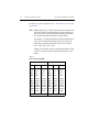
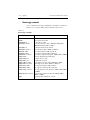
Manual Print History
The print history shown below lists the printing dates of all Revisions and Addenda created
for this manual. The Revision Level letter increases alphabetically as the manual undergoes subsequent updates. Addenda, which are released between Revisions, contain important change information that the user should incorporate immediately into the manual. Addenda are numbered
sequentially. When a new Revision is created, all Addenda associated with the previous Revision
of the manual are incorporated into the new Revision of the manual. Each new Revision includes
a revised copy of this print history page.
Revision A (Document Number 2400S-900-01) ........................................................... August 1998
Revision B (Document Number 2400S-900-01) .......................................................... January 1999
Addendum B (Document Number 2400S-900-02) .......................................................... April 1999
Revision C (Document Number 2400S-900-01) .............................................................. April 1999
Addendum C (Document Number 2400S-900-02) ..................................................November 1999
Revision D (Document Number 2400S-900-01).......................................................... January 2000
Revision E (Document Number 2400S-900-01) ................................................................July 2000
Revision F (Document Number 2400S-900-01) ............................................................... June 2001
Revision G (Document Number 2400S-900-01)............................................................... May 2002
All Keithley product names are trademarks or registered trademarks of Keithley Instruments, Inc.
Other brand names are trademarks or registered trademarks of their respective holders.
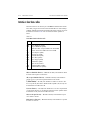
Safety Precautions
The following safety precautions should be observed before using this product and any associated instrumentation. Although
some instruments and accessories would normally be used with non-hazardous voltages, there are situations where hazardous
conditions may be present.
This product is intended for use by qualified personnel who recognize shock hazards and are familiar with the safety precautions
required to avoid possible injury. Read and follow all installation, operation, and maintenance information carefully before using the product. Refer to the manual for complete product specifications.
If the product is used in a manner not specified, the protection provided by the product may be impaired.
The types of product users are:
Responsible body is the individual or group responsible for the use and maintenance of equipment, for ensuring that the equipment is operated within its specifications and operating limits, and for ensuring that operators are adequately trained.
Operators use the product for its intended function. They must be trained in electrical safety procedures and proper use of the
instrument. They must be protected from electric shock and contact with hazardous live circuits.
Maintenance personnel perform routine procedures on the product to keep it operating properly, for example, setting the line
voltage or replacing consumable materials. Maintenance procedures are described in the manual. The procedures explicitly state
if the operator may perform them. Otherwise, they should be performed only by service personnel.
Service personnel are trained to work on live circuits, and perform safe installations and repairs of products. Only properly
trained service personnel may perform installation and service procedures.
Keithley products are designed for use with electrical signals that are rated Installation Category I and Installation Category II,
as described in the International Electrotechnical Commission (IEC) Standard IEC 60664. Most measurement, control, and data
I/O signals are Installation Category I and must not be directly connected to mains voltage or to voltage sources with high transient over-voltages. Installation Category II connections require protection for high transient over-voltages often associated with
local AC mains connections. Assume all measurement, control, and data I/O connections are for connection to Category I sources unless otherwise marked or described in the Manual.
Exercise extreme caution when a shock hazard is present. Lethal voltage may be present on cable connector jacks or test fixtures.
The American National Standards Institute (ANSI) states that a shock hazard exists when voltage levels greater than 30V RMS,
42.4V peak, or 60VDC are present. A good safety practice is to expect that hazardous voltage is present in any unknown
circuit before measuring.
Operators of this product must be protected from electric shock at all times. The responsible body must ensure that operators
are prevented access and/or insulated from every connection point. In some cases, connections must be exposed to potential
human contact. Product operators in these circumstances must be trained to protect themselves from the risk of electric shock.
If the circuit is capable of operating at or above 1000 volts, no conductive part of the circuit may be exposed.
Do not connect switching cards directly to unlimited power circuits. They are intended to be used with impedance limited sources. NEVER connect switching cards directly to AC mains. When connecting sources to switching cards, install protective devices to limit fault current and voltage to the card.
Before operating an instrument, make sure the line cord is connected to a properly grounded power receptacle. Inspect the connecting cables, test leads, and jumpers for possible wear, cracks, or breaks before each use.
When installing equipment where access to the main power cord is restricted, such as rack mounting, a separate main input power disconnect device must be provided, in close proximity to the equipment and within easy reach of the operator.
For maximum safety, do not touch the product, test cables, or any other instruments while power is applied to the circuit under
test. ALWAYS remove power from the entire test system and discharge any capacitors before: connecting or disconnecting ca5/02
bles or jumpers, installing or removing switching cards, or making internal changes, such as installing or removing jumpers.
Do not touch any object that could provide a current path to the common side of the circuit under test or power line (earth) ground. Always make measurements with dry hands while standing on a dry, insulated surface capable of withstanding the voltage being measured.
The instrument and accessories must be used in accordance with its specifications and operating instructions or the safety of the
equipment may be impaired.
Do not exceed the maximum signal levels of the instruments and accessories, as defined in the specifications and operating information, and as shown on the instrument or test fixture panels, or switching card.
When fuses are used in a product, replace with same type and rating for continued protection against fire hazard.
Chassis connections must only be used as shield connections for measuring circuits, NOT as safety earth ground connections.
If you are using a test fixture, keep the lid closed while power is applied to the device under test. Safe operation requires the use
of a lid interlock.
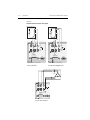
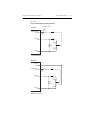
If
The
or
!
is present, connect it to safety earth ground using the wire recommended in the user documentation.
symbol on an instrument indicates that the user should refer to the operating instructions located in the manual.
The
symbol on an instrument shows that it can source or measure 1000 volts or more, including the combined effect of
normal and common mode voltages. Use standard safety precautions to avoid personal contact with these voltages.
The WARNING heading in a manual explains dangers that might result in personal injury or death. Always read the associated
information very carefully before performing the indicated procedure.
The CAUTION heading in a manual explains hazards that could damage the instrument. Such damage may invalidate the warranty.
Instrumentation and accessories shall not be connected to humans.
Before performing any maintenance, disconnect the line cord and all test cables.
To maintain protection from electric shock and fire, replacement components in mains circuits, including the power transformer,
test leads, and input jacks, must be purchased from Keithley Instruments. Standard fuses, with applicable national safety approvals, may be used if the rating and type are the same. Other components that are not safety related may be purchased from
other suppliers as long as they are equivalent to the original component. (Note that selected parts should be purchased only
through Keithley Instruments to maintain accuracy and functionality of the product.) If you are unsure about the applicability
of a replacement component, call a Keithley Instruments office for information.
To clean an instrument, use a damp cloth or mild, water based cleaner. Clean the exterior of the instrument only. Do not apply
cleaner directly to the instrument or allow liquids to enter or spill on the instrument. Products that consist of a circuit board with
no case or chassis (e.g., data acquisition board for installation into a computer) should never require cleaning if handled according to instructions. If the board becomes contaminated and operation is affected, the board should be returned to the factory for
proper cleaning/servicing.
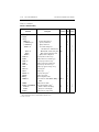
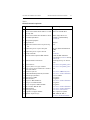
Table of Contents
1
Getting Started
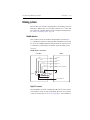
General information ................................................................... 1-2
Warranty information .......................................................... 1-2
Contact information ............................................................ 1-2
Manual addenda .................................................................. 1-2
Safety symbols and terms ................................................... 1-2
Inspection ............................................................................ 1-3
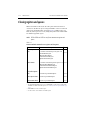
Options and accessories ...................................................... 1-3
General purpose probes ............................................... 1-3
Low thermal probes ..................................................... 1-4
Cables and adapters ..................................................... 1-4
Rack mount kits ........................................................... 1-5
Carrying case ............................................................... 1-5
Product overview ........................................................................ 1-5
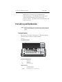
Front and rear panel familiarization ........................................... 1-7
Front panel summary .......................................................... 1-7
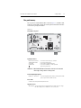
Rear panel summary ........................................................... 1-9
Power-up .................................................................................. 1-10
Line power connection ...................................................... 1-10
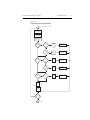
Power-up sequence ........................................................... 1-11
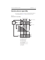
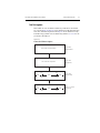
System identification ......................................................... 1-11
Line frequency setting ....................................................... 1-12
Front panel line frequency ......................................... 1-12
Remote command line frequency .............................. 1-12
Fuse replacement .............................................................. 1-13
Cooling fan ............................................................................... 1-13
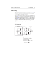
Display ..................................................................................... 1-14
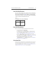
Display format .................................................................. 1-14
EDIT key ........................................................................... 1-14
TOGGLE key .................................................................... 1-15
Status and error messages ................................................. 1-15
Remote display programming ........................................... 1-15
Front panel tests ................................................................ 1-16
Default settings ......................................................................... 1-16
Saving and restoring user setups ....................................... 1-16
Saving setups ............................................................. 1-16
Restoring setups ......................................................... 1-16
Power-on configuration .............................................. 1-17
Factory default settings ..................................................... 1-17
Remote setups ................................................................... 1-20
Menus ....................................................................................... 1-20
Main menu ......................................................................... 1-20
Rules to navigate menus .................................................... 1-24
Editing source and compliance values .............................. 1-24
Toggling the source and measure display fields ................ 1-25
Disabling front panel display ............................................ 1-25
Front panel control ..................................................... 1-26
Remote command programming ................................ 1-26
Configuration menus ......................................................... 1-26
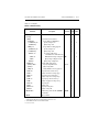
2
Connections
Connection overview .................................................................. 2-2
Front/rear terminals selection .............................................. 2-2
Front panel terminals selection .................................... 2-2
Remote command terminals selection ......................... 2-3
Test fixture interlock .................................................... 2-3
Connections to DUT ................................................................... 2-3
Sensing methods .................................................................. 2-5
4-wire remote sensing .................................................. 2-6
2-wire local sensing ..................................................... 2-7
Guarding methods ............................................................... 2-8
Cable guard .................................................................. 2-8
Ohms guard .................................................................. 2-9
Sense and guard selections ......................................... 2-11
Sense selection ........................................................... 2-11
Guard selection .......................................................... 2-12
3
Basic Source-Measure Operation
WARNING - CAUTION ............................................................ 3-2
Operation overview .................................................................... 3-3
Source-measure capabilities ................................................ 3-3
Compliance limit ................................................................. 3-6
Setting the compliance limit ................................................ 3-7
Front panel compliance limit ....................................... 3-7
Compliance range synchronization .............................. 3-7
Remote compliance limit ............................................. 3-7
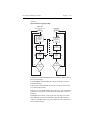
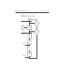
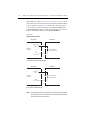
Basic circuit configurations ................................................. 3-8
Operation considerations ............................................................ 3-9
Warm-up .............................................................................. 3-9
Auto zero ............................................................................. 3-9
Front panel auto zero .................................................... 3-9
Remote command auto zero ......................................... 3-9
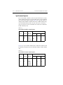
NPLC caching ...................................................................
NPLC cache setup ......................................................
Typical NPLC cache test times ..................................
V-source protection ...........................................................
Front panel V-source protection .................................
Remote command V-source protection ......................
Source delay ......................................................................
Front panel source delay ............................................
Remote command source delay .................................
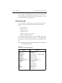
Basic source-measure procedure ..............................................
Output control ...................................................................
Front panel source-measure procedure .............................
Step 1: Select source. .................................................
Step 2: Set source level and compliance limit. ..........
Step 3: Select measurement function and range. .......
Step 4: Turn output on. ..............................................
Step 5: Observe readings on the display. ...................
Step 6: Turn output off. ..............................................
Remote command source-measure procedure ..................
Basic source-measure commands ..............................
Source-measure programming example ....................
Measure only ............................................................................
Front panel measure only ..................................................
Remote command measure only .......................................
Sink operation ..........................................................................
Battery charging/discharging ............................................
Sink programming example ..............................................
4
3-10
3-10
3-11
3-11
3-12
3-12
3-12
3-13
3-13
3-14
3-14
3-14
3-14
3-14
3-16
3-17
3-17
3-18
3-18
3-18
3-19
3-20
3-20
3-21
3-22
3-22
3-24
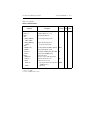
Ohms Measurements
Ohms configuration menu .......................................................... 4-2
Ohms measurement methods ..................................................... 4-3
Selecting ohms measurement method ................................. 4-4
Auto ohms measurements ................................................... 4-4
Manual ohms measurements ............................................... 4-5
Ohms sensing ............................................................................. 4-7
Sense selection .................................................................... 4-8
Offset-compensated ohms .......................................................... 4-9
Enabling/disabling offset-compensated ohms .................... 4-9
Offset-compensated ohms procedure ................................ 4-10
Ohms source readback ............................................................. 4-11
Ohms source readback selection ....................................... 4-11
6-wire ohms measurements ...................................................... 4-11
Remote ohms programming ..................................................... 4-12
Remote ohms commands .................................................. 4-12
Ohms programming example ............................................ 4-13
5
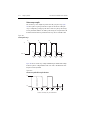
Pulse Mode Operation (Model 2430 only)
Overview .................................................................................... 5-2
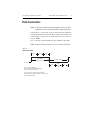
Pulse characteristics .................................................................... 5-3
Pulse width .......................................................................... 5-4
Signal measurement ..................................................... 5-4
Overhead time .............................................................. 5-4
Pulse width delay ......................................................... 5-5
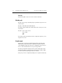
Output off-time .................................................................... 5-5
Reference and zero measurements ............................... 5-5
Overhead time .............................................................. 5-5
Pulse delay ................................................................... 5-6
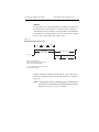
Pulse duty cycle ................................................................... 5-6
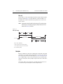
Fast pulse output .................................................................. 5-6
Auto zero ...................................................................... 5-7
Pulse-only ..................................................................... 5-8
Pulse jitter ............................................................................ 5-8
Pulse energy limitations (10A range) ......................................... 5-9
Pulse Mode configuration ......................................................... 5-10
Front panel Pulse Mode configuration .............................. 5-10
Select Pulse Mode, and set pulse width
and pulse delay ....................................................... 5-10
Set pulse measurement speed ..................................... 5-10
Set pulse count ........................................................... 5-10
Disable/enable auto zero ............................................ 5-11
Remote command Pulse Mode configuration ................... 5-11
Basic Pulse Mode operation ..................................................... 5-12
Front panel pulse-measure procedure ............................... 5-12
Step 1: Select Pulse Mode, and set pulse width
and pulse delay. ...................................................... 5-12
Step 2: Set pulse measurement speed. ....................... 5-12
Step 3: Set pulse count. .............................................. 5-12
Step 4: Select source. ................................................. 5-13
Step 5: Set pulse level and compliance limit. ............. 5-13
Step 6: Select measurement function and range. ....... 5-13
Step 7: Turn output on. ............................................... 5-14
Pulse-ohms measurements ................................................ 5-14
Auto and Manual pulse-ohms measurements ............ 5-14
Offset-compensated pulse-ohms measurements ........ 5-14
Remote command pulse-measure operation ..................... 5-15
Basic pulse commands ............................................... 5-15
Ignored settings and invalid commands ..................... 5-15
Pulse-measure programming example ....................... 5-16
Pulse-measure considerations ..................................................
Measurement speed ...........................................................
Filter ..................................................................................
Auto range .........................................................................
Concurrent measurements .................................................
Ohms source readback ......................................................
Toggle key .........................................................................
Offset-compensated ohms .................................................
Source delay ......................................................................
Trigger delay .....................................................................
Input triggers .....................................................................
Output triggers ..................................................................
Auto output-off .................................................................
Output-off state .................................................................
Turning source on .............................................................
SCPI signal oriented measurement commands .................
6
5-16
5-16
5-17
5-17
5-17
5-17
5-17
5-18
5-18
5-18
5-19
5-19
5-19
5-19
5-20
5-20
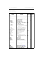
Source-Measure Concepts
Compliance limit ........................................................................ 6-2
Types of compliance ........................................................... 6-2
Maximum compliance values ............................................. 6-3
Compliance examples ......................................................... 6-4
Compliance principles ........................................................ 6-4
Passive load compliance example ................................ 6-4
Active load compliance example ................................. 6-4
Determining compliance limit ............................................ 6-5
Overheating protection ............................................................... 6-6
Overheating conditions ....................................................... 6-6
Power equations to avoid shutdown .................................... 6-7
Model 2400 SourceMeter ............................................ 6-7
Model 2410 SourceMeter ............................................ 6-8
Model 2420 SourceMeter ............................................ 6-8
Models 2425 and 2430 SourceMeters ......................... 6-9
Model 2440 SourceMeter ............................................ 6-9
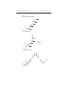
Source-delay-measure cycle ..................................................... 6-10
Sweep waveforms ............................................................. 6-12
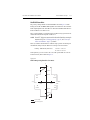
Operating boundaries ............................................................... 6-14
Source or sink ................................................................... 6-14
Duty cycle ......................................................................... 6-14
Model 2400 SourceMeter .......................................... 6-15
Model 2410 SourceMeter .......................................... 6-16
Model 2420 SourceMeter .......................................... 6-17
Models 2425 and 2430 SourceMeters ....................... 6-18
Model 2440 SourceMeter .......................................... 6-20
I-Source operating boundaries .......................................... 6-21
Voltage compliance boundaries .................................. 6-24
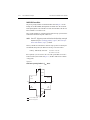
V-Source operating boundaries ......................................... 6-26
Current compliance boundaries ................................. 6-28
Source I measure I and source V measure V ..................... 6-30
Source readback accuracy .......................................... 6-30
Basic circuit configurations ...................................................... 6-31
Source I ............................................................................. 6-31
Source V ............................................................................ 6-32
Measure only (V or I) ........................................................ 6-33
Guard ........................................................................................ 6-34
Cable guard ....................................................................... 6-34
Ohms guard ....................................................................... 6-35
Guard sense ....................................................................... 6-38
Data flow ................................................................................... 6-40
Buffer considerations ........................................................ 6-42
Changing V, I, or Ω measurement function ................ 6-42
Changing MATH function ......................................... 6-43
Changing REL or LIMITS ......................................... 6-43
7
Range, Digits, Speed, and Filters
Range and digits ......................................................................... 7-2
Range ................................................................................... 7-2
Maximum readings ...................................................... 7-2
Ranging limitations ...................................................... 7-2
Manual ranging ............................................................ 7-3
Auto ranging ................................................................ 7-3
Auto range considerations ............................................ 7-3
Auto range change mode .............................................. 7-4
Auto range limits .......................................................... 7-4
Limits evaluation .......................................................... 7-5
Digits ................................................................................... 7-5
Setting display resolution ............................................. 7-5
Remote range and digits programming ............................... 7-5
Range and digits commands ........................................ 7-6
Range and digits programming example ...................... 7-6
Speed .......................................................................................... 7-7
Setting speed ....................................................................... 7-7
Front panel speed control ............................................. 7-7
PULSE SPEED (NPLC) – Model 2430 Pulse Mode ... 7-8
Remote speed programming ................................................ 7-8
Speed commands .......................................................... 7-8
Speed programming example ....................................... 7-9
Filters ......................................................................................... 7-9
Response time considerations ...................................... 7-9
Front panel filter control ................................................... 7-10
Configuring filter ....................................................... 7-10
CONFIGURE FILTERING menu ............................. 7-10
Enabling filter ............................................................ 7-10
Response time ............................................................ 7-11
Remote filter programming ............................................... 7-12
Filter commands ........................................................ 7-12
Filter programming example ..................................... 7-13
8
Relative and Math
Relative ....................................................................................... 8-2
Front panel rel ..................................................................... 8-2
Enabling and disabling rel ........................................... 8-2
Defining a rel value ...................................................... 8-2
Remote rel programming .................................................... 8-3
Rel commands ............................................................. 8-3
Rel programming example .......................................... 8-3
Math operations .......................................................................... 8-4
Built-in math functions ....................................................... 8-4
Power ........................................................................... 8-4
Offset-compensated ohms ............................................ 8-4
Varistor alpha ............................................................... 8-5
Voltage coefficient ....................................................... 8-5
Percent deviation .......................................................... 8-6
Front panel math operations ................................................ 8-6
Remote math operations ..................................................... 8-7
Math commands ........................................................... 8-7
Math programming example ........................................ 8-8
User-defined math functions ............................................... 8-9
Commands for user-defined math functions ................ 8-9
User-defined math function programming example .. 8-10
9
Data Store
Data store overview ....................................................................
Front panel data store .................................................................
Storing readings ..................................................................
Recalling readings ...............................................................
Buffer location number ................................................
Timestamp ...................................................................
Displaying other buffer readings .................................
9-2
9-2
9-2
9-2
9-2
9-3
9-3
Buffer statistics .................................................................... 9-3
Minimum and maximum .............................................. 9-3
Peak-to-peak ................................................................. 9-3
Average ......................................................................... 9-4
Standard deviation ........................................................ 9-4
Timestamp format ............................................................... 9-4
Timestamp accuracy ............................................................ 9-5
Buffer considerations .......................................................... 9-5
Using :TRACe commands to store data ....................... 9-5
Using :READ? to store data ......................................... 9-5
Remote command data store ...................................................... 9-6
Data store commands .......................................................... 9-6
Data store programming example ....................................... 9-7
10
Sweep Operation
Sweep types .............................................................................. 10-2
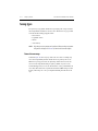
Linear staircase sweep ....................................................... 10-2
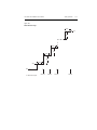
Logarithmic staircase sweep ............................................. 10-4
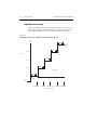
Custom sweep ................................................................... 10-5
Custom sweep examples ............................................ 10-6
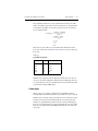
Source memory sweep ...................................................... 10-7
Sweep configuration ................................................... 10-7
Saving and restoring source memory setups .............. 10-7
Saving multiple source memory sweeps .................... 10-8
Saved source memory configurations ........................ 10-8
Sweep branching ...................................................... 10-10
Diode test example ................................................... 10-12
Configuring and running a sweep ........................................... 10-14
Front panel sweep operation ........................................... 10-14
Sweep configuration menu ....................................... 10-14
Setting delay ............................................................. 10-16
Trigger count and sweep points ............................... 10-16
Performing sweeps ................................................... 10-16
Performing a linear staircase sweep ......................... 10-17
Performing a log staircase sweep ............................. 10-18
Performing a custom sweep ..................................... 10-19
Performing a source memory sweep ........................ 10-21
Remote sweep operation ................................................. 10-22
Staircase sweep commands ...................................... 10-22
Staircase sweep programming example ................... 10-22
Custom sweep commands ........................................ 10-24
Custom sweep programming example ..................... 10-25
Source memory sweep commands ........................... 10-25
Source memory sweep programming example ........ 10-26
Sweep branching program example .......................................
Pulse Mode sweeps (Model 2430 only) .................................
Front panel Pulse Mode sweep procedure ......................
Remote Pulse Mode sweep operation .............................
11
10-27
10-32
10-33
10-34
Triggering
Front panel trigger operation .................................................... 11-2
Front panel trigger model .................................................. 11-2
Event detection .......................................................... 11-2
Idle ............................................................................. 11-2
Arm layer ................................................................... 11-4
Trigger layer .............................................................. 11-5
Counters ..................................................................... 11-6
Output triggers ........................................................... 11-6
Bench defaults ........................................................... 11-7
Operation summary ................................................... 11-7
Configuring triggering ...................................................... 11-8
Trigger configuration menu ....................................... 11-8
Remote trigger operation ....................................................... 11-11
Remote trigger model ..................................................... 11-11
Idle and initiate ........................................................ 11-11
Event detection ........................................................ 11-13
Arm layer ................................................................. 11-13
Trigger layer ............................................................ 11-14
Counters ................................................................... 11-16
Output triggers ......................................................... 11-16
GPIB defaults ........................................................... 11-17
Operation summary ................................................. 11-17
Remote trigger commands .............................................. 11-18
Trigger link ............................................................................. 11-19
Input trigger requirements ............................................... 11-19
Output trigger specifications ........................................... 11-20
Triggering examples ............................................................... 11-20
Front panel trigger example ............................................ 11-20
External trigger example ................................................. 11-23
Trigger link connections .......................................... 11-24
Instrument configurations ........................................ 11-25
Operation ................................................................. 11-26
Remote trigger example .................................................. 11-28
Pulse Mode triggering (Model 2430) ..................................... 11-30
Trigger models ................................................................ 11-30
Idle ........................................................................... 11-33
Source event detector ............................................... 11-33
Pulse delay ............................................................... 11-33
Source action ............................................................ 11-33
Pulse width ............................................................... 11-33
Measure action ......................................................... 11-33
Output triggers ......................................................... 11-34
Invalid trigger settings ..................................................... 11-34
Front panel operation ............................................... 11-34
Remote operation ..................................................... 11-34
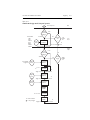
12
Limit Testing
Types of limits .......................................................................... 12-2
Pass/fail information .......................................................... 12-3
Data flow ........................................................................... 12-3
Limit 1 test (compliance) .................................................. 12-3
Limit 2, limit 3, and limit 5-12 tests .................................. 12-4
Limit test modes ................................................................ 12-4
Binning .............................................................................. 12-4
Operation overview .................................................................. 12-5
Grading mode .................................................................... 12-5
Binning control .......................................................... 12-5
Pass condition ............................................................. 12-8
Fail condition ............................................................. 12-8
Sorting mode ..................................................................... 12-9
Binning ....................................................................... 12-9
Binning systems ...................................................................... 12-11
Handler interface ............................................................. 12-11
Digital I/O connector ............................................... 12-11
Digital output lines ................................................... 12-12
SOT line ................................................................... 12-12
/INT line ................................................................... 12-12
Handler types ................................................................... 12-12
Category pulse component handler .......................... 12-13
Category register component handler ...................... 12-13
Basic binning systems ..................................................... 12-14
Single-element device binning ................................. 12-14
Multiple-element device binning ............................. 12-15
Digital output clear pattern .............................................. 12-17
Enabling auto-clear .................................................. 12-17
Auto-clear timing ..................................................... 12-18
Configuring and performing limit tests ..................................
Configuring limit tests .....................................................
Performing front panel limit tests ...................................
Step 1: Configure test system. .................................
Step 2: Configure source-measure functions. ..........
Step 3: Configure limit tests. ...................................
Step 4: Turn output on. ............................................
Step 5: Start testing process. ....................................
Step 6: Stop testing process. ....................................
Remote limit testing ...............................................................
Limit commands .............................................................
Limit test programming example ....................................
13
12-19
12-19
12-21
12-21
12-21
12-22
12-22
12-22
12-22
12-23
12-23
12-24
Digital I/O Port, Safety Interlock, and Output Configuration
Digital I/O port ......................................................................... 13-2
Port configuration .............................................................. 13-2
Digital output lines .................................................... 13-2
SOT line ..................................................................... 13-3
Interlock line .............................................................. 13-3
+5V output ................................................................. 13-3
Digital output configuration .............................................. 13-3
Sink operation ............................................................ 13-3
Source operation ........................................................ 13-4
Controlling digital output lines ......................................... 13-4
Front panel digital output control .............................. 13-4
Remote digital output control .................................... 13-5
Safety interlock ........................................................................ 13-5
Front panel output configuration .............................................. 13-7
Configure OUTPUT menu ................................................ 13-7
Output-off states ................................................................ 13-8
HIGH IMPEDANCE ................................................. 13-8
NORMAL .................................................................. 13-8
ZERO ......................................................................... 13-9
GUARD ..................................................................... 13-9
Output-off states and inductive loads .............................. 13-10
Remote output configuration .................................................. 13-11
Output configuration commands ..................................... 13-11
Output configuration programming example .................. 13-12
14
Remote Operations
Differences: remote vs. local operation .................................... 14-2
Operation enhancements (remote operation) .................... 14-2
Math expressions ........................................................ 14-2
Concurrent measurements .......................................... 14-2
Local-to-remote transition ................................................. 14-2
Remote-to-local transition ................................................. 14-3
Selecting an interface ............................................................... 14-3
GPIB operation ......................................................................... 14-4
GPIB standards .................................................................. 14-4
GPIB connections .............................................................. 14-4
Primary address ................................................................. 14-6
General bus commands ............................................................. 14-7
REN (remote enable) ......................................................... 14-7
IFC (interface clear) .......................................................... 14-7
LLO (local lockout) ........................................................... 14-8
GTL (go to local) ............................................................... 14-8
DCL (device clear) ............................................................ 14-8
SDC (selective device clear) .............................................. 14-8
GET (group execute trigger) ............................................. 14-8
SPE, SPD (serial polling) .................................................. 14-9
Front panel GPIB operation ...................................................... 14-9
Error and status messages ................................................. 14-9
GPIB status indicators ....................................................... 14-9
REM ........................................................................... 14-9
TALK ....................................................................... 14-10
LSTN ........................................................................ 14-10
SRQ .......................................................................... 14-10
LOCAL key ..................................................................... 14-10
Programming syntax ............................................................... 14-11
Command words ............................................................. 14-11
Commands and command parameters ..................... 14-11
Query commands ............................................................. 14-13
Case sensitivity ................................................................ 14-13
Long-form and short-form versions ................................ 14-14
Short-form rules .............................................................. 14-14
Program messages ........................................................... 14-15
Single command messages ....................................... 14-15
Multiple command messages ................................... 14-15
Command path rules ................................................ 14-16
Using common and SCPI commands in the
same message ....................................................... 14-16
Program message terminator (PMT) ........................ 14-16
Command execution rules ........................................ 14-16
Response messages .........................................................
Sending a response message ....................................
Multiple response messages ....................................
Response message terminator (RMT) .....................
Message exchange protocol ............................................
RS-232 interface operation ....................................................
Sending and receiving data .............................................
Baud rate .........................................................................
Data bits and parity .........................................................
Terminator .......................................................................
Flow control (signal handshaking) ..................................
RS-232 connections ........................................................
Error messages ................................................................
Programming example ....................................................
15
14-17
14-17
14-17
14-17
14-17
14-18
14-18
14-18
14-18
14-19
14-19
14-19
14-21
14-21
Status Structure
Overview .................................................................................. 15-2
Status byte and SRQ ......................................................... 15-2
Status register sets ............................................................. 15-2
Queues ............................................................................... 15-2
Clearing registers and queues ................................................... 15-4
Programming and reading registers ......................................... 15-5
Programming enable registers ........................................... 15-5
Reading registers ............................................................... 15-6
Status byte and service request (SRQ) ..................................... 15-7
Status byte register ............................................................ 15-8
Service request enable register .......................................... 15-9
Serial polling and SRQ ..................................................... 15-9
SPE, SPD (serial polling) .......................................... 15-9
Status byte and service request commands ..................... 15-10
Programming example – set MSS (B6)
when error occurs ................................................ 15-10
Status register sets .................................................................. 15-11
Register bit descriptions .................................................. 15-11
Standard Event Register ........................................... 15-11
Operation Event Register ......................................... 15-12
Measurement Event Register ................................... 15-13
Questionable Event Register .................................... 15-15
Condition registers .......................................................... 15-16
Event registers ................................................................. 15-16
Event enable registers ..................................................... 15-17
Programming example — program and
read register set .................................................... 15-18
Queues .................................................................................... 15-18
Output queue ................................................................... 15-18
Error queue ...................................................................... 15-19
Programming example — read error queue ............. 15-20
16
Common Commands
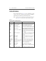
Command summary .................................................................. 16-2
Command reference .................................................................. 16-3
*IDN? — identification query ........................................... 16-3
*OPC — operation complete ............................................ 16-3
*OPC? — operation complete query ................................ 16-3
*OPC programming example ..................................... 16-4
*SAV <NRf> — save ........................................................ 16-4
*RCL <NRf> — recall ...................................................... 16-4
*SAV, *RCL programming example .......................... 16-5
*RST — reset .................................................................... 16-5
*TRG — trigger ................................................................ 16-5
*TRG programming example .................................... 16-6
*TST? — self-test query ................................................... 16-6
*WAI — wait-to-continue ................................................. 16-7
17
SCPI Signal Oriented Measurement Commands
Command summary .................................................................. 17-2
Configuring measurement function .......................................... 17-2
:CONFigure:<function> .................................................... 17-2
Acquiring readings ................................................................... 17-3
:FETCh? ............................................................................ 17-3
[:SENSe[1]]:DATA[:LATest]? ........................................... 17-4
:READ? ............................................................................. 17-4
:MEASure[:<function>]? .................................................. 17-5
18
SCPI Command Reference
Reference tables ........................................................................ 18-2
Calculate subsystems .............................................................. 18-24
CALCulate[1] ......................................................................... 18-24
Select (create) math expression name ............................. 18-24
CATalog? .................................................................. 18-24
NAME <name> ........................................................ 18-24
Program examples .................................................... 18-26
:DELete[:SELected] <name> ................................... 18-29
:DELete:ALL ........................................................... 18-29
Assign unit suffix ............................................................. 18-29
:UNITs <name> ....................................................... 18-29
Define math expression ...................................................
[:EXPRession] <form> or [:DEFine] <form> .........
Enable and read math expression result ..........................
:STATe <b> ..............................................................
:DATA? ....................................................................
:LATest? ...................................................................
CALCulate2 ...........................................................................
Select input path ..............................................................
FEED <name> .........................................................
Null feed reading .............................................................
OFFSet <n> .............................................................
ACQuire ...................................................................
STATe <b> ...............................................................
Read CALC2 ...................................................................
DATA? .....................................................................
LATest? ....................................................................
Configure and control limit tests .....................................
COMPliance:FAIL <name> .....................................
[:DATA] <n> ............................................................
SOURce2 <NRf> |<NDN> ......................................
PASS:SOURce2 <NRf> | NDN ...............................
STATe <b> ...............................................................
FAIL? .......................................................................
Composite testing ............................................................
PASS:SOURce2 <NRf> | NDN ...............................
FAIL:SOURce2 <NRf> | <NDN> ...........................
FAIL:SMLocation <NRf> | NEXT .........................
PASS:SMLocation <NRf> | NEXT .........................
BCONtrol <name> ..................................................
MODE <name> .......................................................
Clear test results ..............................................................
[:IMMediate] ............................................................
AUTO <b> ...............................................................
CALCulate3 ...........................................................................
Select statistic ..................................................................
FORMat <name> .....................................................
Acquire statistic ..............................................................
:DATA? ....................................................................
DISPlay subsystem ................................................................
Control display ................................................................
DIGits <n> ...............................................................
ENABle <b> ............................................................
ATTRibutes? ............................................................
CNDisplay ...............................................................
18-30
18-30
18-33
18-33
18-33
18-34
18-34
18-34
18-34
18-35
18-35
18-35
18-35
18-35
18-35
18-36
18-36
18-36
18-36
18-37
18-39
18-39
18-40
18-40
18-40
18-41
18-42
18-42
18-43
18-43
18-44
18-44
18-44
18-44
18-44
18-44
18-45
18-45
18-46
18-46
18-46
18-46
18-47
18-47
Read display .................................................................... 18-47
DATA? ...................................................................... 18-47
Define :TEXT messages .................................................. 18-48
DATA <a> ................................................................ 18-48
STATe <b> ................................................................ 18-48
FORMat subsystem ................................................................ 18-49
Data format ...................................................................... 18-49
[:DATA] <type>[,length] .......................................... 18-49
Data elements .................................................................. 18-51
ELEMents <item list> .............................................. 18-51
SOURce2 <name> ................................................... 18-55
CALC data elements ....................................................... 18-55
CALCulate <item list> ............................................. 18-55
Byte order ........................................................................ 18-56
BORDer <name> ..................................................... 18-56
Status register format ....................................................... 18-56
SREGister <name> .................................................. 18-56
OUTPut subsystem ................................................................. 18-57
Turn source on or off ....................................................... 18-57
[:STATe] <b> ............................................................ 18-57
Interlock control .............................................................. 18-58
STATe <b> ................................................................ 18-58
TRIPped? ................................................................. 18-58
Output-off states .............................................................. 18-58
SMODe .................................................................... 18-58
ROUTe subsystem .................................................................. 18-59
Select input jacks ............................................................. 18-59
TERMinals <name> ................................................. 18-59
SENSe1 subsystem ................................................................. 18-60
Select measurement functions ......................................... 18-60
CONCurrent <b> ...................................................... 18-60
[:ON] <function list> ............................................... 18-61
OFF <function list> .................................................. 18-61
ALL .......................................................................... 18-62
COUNt? ................................................................... 18-62
STATe? <name> ....................................................... 18-62
RESistance:MODE <name> .................................... 18-63
RESistance:OCOMpensated <b> ............................. 18-63
Select measurement range ............................................... 18-64
[:UPPer] <n> ............................................................ 18-65
Select auto range ............................................................. 18-67
AUTO <b> ............................................................... 18-67
LLIMit <n> .............................................................. 18-67
ULIMit <n> .............................................................. 18-68
Set compliance parameters .............................................
[:LEVel] <n> ............................................................
RSYNhronize <b> ...................................................
TRIPped? .................................................................
Set measurement speed ...................................................
NPLCycles <n> .......................................................
Configure and control filter .............................................
TCONtrol <name> ...................................................
COUNt <n> .............................................................
[:STATe] <b> ...........................................................
SOURce subsystem ................................................................
SOURce[1] ......................................................................
Control source output-off ................................................
[:IMMediate] ............................................................
AUTO ......................................................................
Select function modes .....................................................
SHAPe <name> (Model 2430 only) ........................
[:MODE] <name> ....................................................
Select sourcing mode ......................................................
MODE <name> .......................................................
Select range .....................................................................
RANGe <n> .............................................................
AUTO <b> ...............................................................
Set amplitude for fixed source ........................................
[:IMMediate][:AMPLitude] <n> .............................
TRIGgered[:AMPLitude] <n> .................................
Set voltage limit ..............................................................
[:LEVel] <n> ............................................................
Set delay ..........................................................................
DELay <n> ..............................................................
AUTO <b> ...............................................................
Configure voltage and current sweeps ............................
RANGing <name> ...................................................
SPACing <name> .....................................................
STARt <n>................................................................
STOP <n> ................................................................
CENTer <n> .............................................................
SPAN <n> ................................................................
STEP <n> ................................................................
POINts <n> ..............................................................
DIRection <name> ..................................................
18-68
18-68
18-69
18-70
18-70
18-70
18-71
18-71
18-71
18-72
18-72
18-72
18-72
18-72
18-73
18-73
18-73
18-74
18-74
18-74
18-75
18-75
18-77
18-77
18-77
18-79
18-80
18-80
18-83
18-83
18-83
18-84
18-84
18-85
18-85
18-85
18-87
18-87
18-88
18-90
18-91
Configure list ................................................................... 18-91
CURRent <NRf list>................................................. 18-91
VOLTage <NRf list> ................................................ 18-91
APPend <NRf list> .................................................. 18-92
POINts? .................................................................... 18-93
STARt <n> ............................................................... 18-93
Configure memory sweep ................................................ 18-93
SAVE <NRf> ........................................................... 18-94
POINts <NRf> ......................................................... 18-95
STARt <NRf> .......................................................... 18-95
RECall <NRf> .......................................................... 18-96
Set scaling factor ............................................................. 18-96
TRIGgered:SFACtor <n> ......................................... 18-96
TRIGgered:SFACtor:STATe <b> ............................. 18-96
Sweep and list program examples ................................... 18-96
Linear voltage sweep ................................................ 18-96
Voltage list ................................................................ 18-97
Logarithmic current sweep ....................................... 18-97
Current list ................................................................ 18-98
Soak time ......................................................................... 18-99
SOAK <NRf> ........................................................... 18-99
Pulse Mode delays (Model 2430 only) ........................... 18-99
WIDth <n> ............................................................... 18-99
DELay <n> ............................................................. 18-100
SOURce2 ....................................................................... 18-100
Setting digital output ..................................................... 18-100
[:LEVel] <NRf> | <NDN> ..................................... 18-100
MODE <name> ...................................................... 18-101
BSTate <b> ............................................................. 18-102
BSIZe <n> .............................................................. 18-102
Clearing digital output ................................................... 18-102
[:IMMediate] .......................................................... 18-102
AUTO <b> ............................................................. 18-103
DELay <n> ............................................................. 18-103
STATus subsystem ................................................................ 18-104
Read event registers ....................................................... 18-104
[:EVENt]? .............................................................. 18-104
Program event enable registers ...................................... 18-104
ENABle <NDN> or <NRf> ................................... 18-104
Read condition registers ................................................ 18-104
CONDition? ........................................................... 18-104
Select default conditions ............................................... 18-105
PRESet ................................................................... 18-105
Error queue ....................................................................
[:NEXT]? ...............................................................
CLEar .....................................................................
ENABle <list> .......................................................
DISable <list> ........................................................
SYSTem subsystem ..............................................................
Default conditions .........................................................
PRESet ...................................................................
POSetup .................................................................
Control remote sensing .................................................
RSENse <b> ..........................................................
Select guard mode .........................................................
GUARd <name> ....................................................
Initialize memory ..........................................................
INITialize ...............................................................
Control beeper ...............................................................
[:IMMediate] <freq, time> ...................................
STATe <b> .............................................................
Control auto zero ...........................................................
STATe <name> ......................................................
Control NPLC caching ..................................................
CACHing ...............................................................
Select power line frequency setting ..............................
LFRequency <freq> ...............................................
AUTO <b> .............................................................
Error queue ....................................................................
[:NEXT]? ...............................................................
ALL? ......................................................................
COUNt? .................................................................
CODE[:NEXT]? ....................................................
CODE:ALL? ..........................................................
CLEar .....................................................................
Simulate key presses .....................................................
KEY .......................................................................
Read version of SCPI standard .....................................
VERSion? ..............................................................
RS-232 interface ...........................................................
LOCal ....................................................................
RWLock <b> .........................................................
Query timestamp ...........................................................
TIME? ....................................................................
Reset timestamp ............................................................
RESet .....................................................................
Auto reset timestamp ....................................................
RESet:AUTO <b> ..................................................
18-105
18-105
18-105
18-105
18-106
18-106
18-106
18-106
18-106
18-107
18-107
18-108
18-108
18-108
18-108
18-109
18-109
18-109
18-110
18-110
18-110
18-110
18-111
18-111
18-111
18-112
18-112
18-112
18-112
18-112
18-112
18-112
18-113
18-113
18-115
18-115
18-115
18-115
18-115
18-116
18-116
18-116
18-116
18-116
18-116
Auto range change mode ............................................... 18-117
RCMode <name> ................................................... 18-117
TRACe subsystem ................................................................ 18-117
Read and clear buffer ..................................................... 18-117
DATA? .................................................................... 18-117
CLEar ..................................................................... 18-118
Configure and control buffer ......................................... 18-118
FREE? .................................................................... 18-118
POINts <n> ............................................................ 18-118
ACTual? ................................................................. 18-118
FEED <name> ........................................................ 18-119
CONTrol <name> .................................................. 18-119
Select timestamp format ................................................ 18-119
FORMat <name> ................................................... 18-119
TRIGger subsystem .............................................................. 18-120
Clear input triggers ........................................................ 18-120
CLEar ..................................................................... 18-120
Initiate source/measure cycle ........................................ 18-120
INITiate .................................................................. 18-120
Abort source/measure cycle .......................................... 18-121
ABORt ................................................................... 18-121
Program trigger model .................................................. 18-121
COUNt <n> ............................................................ 18-121
DELay <n> ............................................................. 18-122
SOURce <name> ................................................... 18-123
TIMer <n> .............................................................. 18-124
DIRection <name> ................................................. 18-124
INPut <event list> .................................................. 18-124
ILINe <NRf> .......................................................... 18-125
OLINe <NRf> ........................................................ 18-125
OUTPut <event list> .............................................. 18-126
A
Specifications
B
Status and Error Messages
Introduction ...............................................................................
Status and error messages ..........................................................
Eliminating common SCPI errors .............................................
-113, “Undefined header” ...........................................
-410, “Query INTERRUPTED” ..................................
-420, “Query UNTERMINATED” ..............................
B-2
B-2
B-8
B-8
B-8
B-9
C
Data Flow
Introduction ...............................................................................
FETCh? ..............................................................................
CALCulate[1]:DATA? .......................................................
CALCulate2:DATA? ..........................................................
TRACe:DATA? ..................................................................
CALCulate3:DATA? ..........................................................
D
C-2
C-3
C-4
C-4
C-4
C-4
IEEE-488 Bus Overview
Introduction ............................................................................... D-2
Bus description .......................................................................... D-3
Bus lines .................................................................................... D-5
Data lines ........................................................................... D-5
Bus management lines ....................................................... D-5
Handshake lines ................................................................. D-5
Bus commands .......................................................................... D-7
Uniline commands ............................................................. D-8
Universal multiline commands .......................................... D-8
Addressed multiline commands ......................................... D-9
Address commands ............................................................ D-9
Unaddress commands ........................................................ D-9
Common commands ........................................................ D-10
SCPI commands ............................................................... D-10
Command codes ............................................................... D-10
Typical command sequences ............................................ D-12
IEEE command groups .................................................... D-13
Interface function codes .......................................................... D-14
E
IEEE-488 and SCPI Conformance Information
Introduction ................................................................................ E-2
F
Contact Check Function
Introduction ................................................................................
Overview ....................................................................................
Description ..........................................................................
Block diagram .....................................................................
Operation ....................................................................................
DUT connections ................................................................
Contact check threshold resistances ....................................
Contact check failure indications ........................................
Auto and manual ohms .......................................................
Trigger model operation ......................................................
Sweep and binning considerations .............................................
F-2
F-2
F-2
F-3
F-4
F-4
F-5
F-5
F-5
F-6
F-6
Sweep limitations ............................................................... F-6
Staircase and custom sweeps ...................................... F-6
Source memory sweeps ............................................... F-6
Limit test sequence ............................................................. F-7
Binning failure indications (grading mode) ..................... F-10
Auto clear on, end binning ........................................ F-10
Auto clear on, immediate binning ............................. F-10
Auto clear off, end binning ....................................... F-10
Auto clear off, immediate binning ............................ F-11
Front panel contact check operation ........................................ F-11
Menu selections ................................................................ F-11
Using contact check ......................................................... F-12
Using event detection with contact check ................. F-13
Using pass/fail with contact check ............................ F-13
Remote contact check operation .............................................. F-14
Contact check remote commands ..................................... F-14
Contact check programming example .............................. F-16
Contact check command reference .......................................... F-17
Configure and control contact check ................................ F-17
CCHeck <b> ............................................................. F-17
RESistance <NRf> .................................................... F-17
Configure and control contact check limit test ................. F-17
STATe <b> ................................................................. F-17
FAIL? ........................................................................ F-18
SOURce2 <NRf> |<NDN> ....................................... F-18
Configure and control contact check event detection ....... F-19
SOURce <name> ...................................................... F-19
TOUT <NRf> ............................................................ F-20
Contact check defaults ............................................................. F-20
G
GPIB 488.1 Protocol
Introduction ............................................................................... G-2
Selecting the 488.1 protocol ...................................................... G-2
Protocol differences ................................................................... G-3
Message exchange protocol (MEP) .................................... G-3
Using SCPI-based programs .............................................. G-3
NRFD hold-off ................................................................... G-4
NDAC hold-off ................................................................... G-4
Trigger-on-talk ................................................................... G-5
Message available ............................................................... G-5
General operation notes ...................................................... G-5
GPIB reading speed comparisons .............................................. G-6
Sweep operation ................................................................. G-6
Single-shot operation .......................................................... G-8
List of Illustrations
1
Getting Started
Figure 1-1
Figure 1-2
Figure 1-3
SourceMeter front panel ........................................................ 1-7
SourceMeter rear panel .......................................................... 1-9
Main menu tree .................................................................... 1-23
2
Connections
Figure 2-1
Figure 2-2
Figure 2-3
Figure 2-4
Figure 2-5
Terminal voltage differentials (rear panel) ............................. 2-4
Two-wire connections (local sense) ....................................... 2-5
Four-wire connections (remote sense) ................................... 2-6
High-impedance guarding (cable guard) ............................... 2-8
Guarded ohms measurements (ohms guard) ........................ 2-10
3
Basic Source-Measure Operation
Figure 3-1
Fundamental source measure configuration .......................... 3-8
4
Ohms Measurements
Figure 4-1
Figure 4-2
Figure 4-3
Ohms configuration menu tree ............................................... 4-2
2-wire resistance sensing ....................................................... 4-7
4-wire resistance sensing ....................................................... 4-8
5
Pulse Mode Operation (Model 2430 only)
Figure 5-1
Figure 5-2
Figure 5-3
Figure 5-4
Pulse period ...........................................................................
Pulse-measure timing .............................................................
Pulse-measure timing (auto zero off) .....................................
Pulse-only timing ...................................................................
6
Source-Measure Concepts
Figure 6-1
Figure 6-2
Figure 6-3
Figure 6-4
Figure 6-5
Figure 6-6
Figure 6-7
Figure 6-8
Figure 6-9
Figure 6-10
Figure 6-11
Figure 6-12
Source-delay-measure (SDM) cycle ....................................
Simplified trigger model ......................................................
Three basic sweep waveform types .....................................
Model 2400 operating boundaries (Tamb ≤30°C) ...............
Model 2410 operating boundaries (Tamb ≤30°C) ...............
Model 2420 operating boundaries (Tamb ≤30°C) ...............
Model 2425/2430 operating boundaries (Tamb ≤30°C) ......
Model 2440 operating boundaries (Tamb ≤30°C) ...............
I-Source output characteristics .............................................
I-Source limit lines ...............................................................
I-Source operating examples ...............................................
V-Source output characteristics ...........................................
5-2
5-3
5-7
5-8
6-10
6-11
6-13
6-15
6-16
6-17
6-19
6-20
6-22
6-23
6-25
6-27
Figure 6-13
Figure 6-14
Figure 6-15
Figure 6-16
Figure 6-17
Figure 6-18
Figure 6-19
Figure 6-20
Figure 6-21
V-Source limit lines .............................................................. 6-28
V-Source operating examples ............................................... 6-29
Source I ................................................................................ 6-31
Source V ............................................................................... 6-32
Measure only (V or I) ........................................................... 6-33
High-impedance measurements ........................................... 6-36
In-circuit ohms measurements ............................................. 6-37
In-circuit ohms measurements using guard sense ................ 6-39
Data flow front panel ............................................................ 6-41
7
Range, Digits, Speed, and Filters
Figure 7-1
Figure 7-2
Figure 7-3
Speed configuration menu tree ............................................... 7-8
Moving average and repeating filters ................................... 7-11
Filter configuration menu tree .............................................. 7-12
8
Relative and Math
Figure 8-1
Figure 8-2
Math configuration menu tree ................................................ 8-7
Connections for voltage coefficient tests ................................ 8-9
10
Sweep Operation
Figure 10-1
Figure 10-2
Figure 10-3
Figure 10-4
Figure 10-5
Figure 10-6
Figure 10-7
Figure 10-8
Figure 10-9
Figure 10-10
Linear staircase sweep .......................................................... 10-3
Logarithmic staircase sweep
(example 5-point sweep from 1 to 10 volts) ........................10-4
Custom pulse sweep ............................................................. 10-6
Custom sweep with different pulse durations ...................... 10-6
Six-point test branching example ....................................... 10-10
Typical diode I-V curve and test points (not to scale) ........ 10-12
Sweep configuration menu tree .......................................... 10-15
Connections for diode I-V tests .......................................... 10-23
Diode I-V curve .................................................................. 10-23
Pulse Mode linear staircase sweep ..................................... 10-32
11
Triggering
Figure 11-1
Figure 11-2
Figure 11-3
Figure 11-4
Figure 11-5
Figure 11-6
Figure 11-7
Figure 11-8
Figure 11-9
Figure 11-10
Front panel trigger model ..................................................... 11-3
Trigger configuration menu tree ......................................... 11-10
Remote trigger model ......................................................... 11-12
Measure action ................................................................... 11-15
Rear panel pinout ............................................................... 11-19
Trigger link input pulse specifications ............................... 11-19
Trigger link output pulse specifications ............................. 11-20
Trigger model for front panel trigger example ................... 11-22
DUT test system ................................................................. 11-23
Trigger link connections ..................................................... 11-24
Figure 11-11
Figure 11-12
Figure 11-13
Figure 11-14
Operation model for triggering example ...........................
Trigger model for remote trigger example .........................
2430 Pulse Mode trigger model (front panel operation) ....
2430 Pulse Mode trigger model (remote operation) ..........
11-27
11-29
11-31
11-32
12
Limit Testing
Figure 12-1
Figure 12-2
Figure 12-3
Figure 12-4
Figure 12-5
Figure 12-6
Figure 12-7
Figure 12-8
Figure 12-9
Figure 12-10
Figure 12-11
Limit tests ............................................................................ 12-2
Grading mode limit testing .................................................. 12-6
Immediate binning ............................................................... 12-7
End binning .......................................................................... 12-7
Sorting mode limit testing ................................................. 12-10
Handler interface connections ........................................... 12-11
Binning system single-element devices ............................. 12-14
Binning system multiple-element devices ......................... 12-16
Digital output auto-clear timing example .......................... 12-18
Limits configuration menu tree .......................................... 12-21
Diode pass/fail limits ......................................................... 12-25
13
Digital I/O Port, Safety Interlock, and Output Configuration
Figure 13-1
Figure 13-2
Figure 13-3
Figure 13-4
Figure 13-5
Digital I/O port ....................................................................
Sink operation ......................................................................
Source operation ..................................................................
Using test fixture interlock ...................................................
Output configuration menu tree ...........................................
14
Remote Operations
Figure 14-1
Figure 14-2
Figure 14-3
Figure 14-4
IEEE-488 connector ............................................................. 14-4
IEEE-488 connections ......................................................... 14-5
IEEE-488 connector location ............................................... 14-6
RS-232 interface connector ............................................... 14-20
15
Status Structure
Figure 15-1
Figure 15-2
Figure 15-3
Figure 15-4
Figure 15-5
Figure 15-6
Figure 15-7
SourceMeter status register structure ................................... 15-3
16-bit status register ............................................................. 15-5
Status byte and service request (SRQ) ................................. 15-7
Standard event status .......................................................... 15-12
Operation event status ........................................................ 15-13
Measurement event status .................................................. 15-14
Questionable event status ................................................... 15-15
13-2
13-3
13-4
13-6
13-8
18
SCPI Command Reference
Figure 18-1
Figure 18-2
Figure 18-3
ASCII data format .............................................................. 18-49
IEEE-754 single precision data format (32 data bits) ........ 18-50
Key-press codes ................................................................ 18-114
C
Data Flow
Figure C-1
Data flow block diagram ....................................................... C-2
D
IEEE-488 Bus Overview
Figure D-1
Figure D-2
Figure D-3
IEEE-488 bus configuration .................................................. D-4
IEEE-488 handshake sequence ............................................. D-6
Command codes .................................................................. D-11
F
Contact Check Function
Figure F-1
Figure F-2
Figure F-3
Figure F-4
Figure F-5
Figure F-6
Source of Kelvin resistance errors ........................................
Contact check block diagram ................................................
Contact check DUT connections ...........................................
Contact check limit test sequence .........................................
Grading mode contact check limit testing .............................
Sorting mode contact check limit testing ..............................
G
GPIB 488.1 Protocol
Figure G-1
IEEE-488 handshake sequence ............................................. G-4
F-2
F-3
F-4
F-7
F-8
F-9
List of Tables
1
Getting Started
Table 1-1
Table 1-2
Table 1-3
Table 1-4
Table 1-5
Table 1-6
Table 1-7
Table 1-8
Table 1-9
Table 1-10
Table 1-11
Table 1-12
Line frequency remote commands .......................................
Power line fuse .....................................................................
Basic display commands ......................................................
Factory default settings ........................................................
Main menu ...........................................................................
Measurement configuration menus ......................................
Source and range configuration menus ................................
Rel, filter, and limit configuration menus ............................
Trigger configuration menu .................................................
Sweep, digits, speed, and data store configuration menus ...
Output and display configuration menus .............................
Sweep, digits, speed, and output configuration menus ........
3
Basic Source-Measure Operation
Table 3-1
Table 3-2
Table 3-3
Table 3-4
Table 3-5
Table 3-6
Table 3-7
Table 3-8
Source-measure capabilities .................................................. 3-4
Compliance limits .................................................................. 3-6
Compliance commands .......................................................... 3-7
Auto source delay ................................................................ 3-13
Basic source-measure commands ........................................ 3-18
Basic source-measure programming example ..................... 3-19
Measure only programming example .................................. 3-21
Sink programming example ................................................. 3-24
1-12
1-13
1-15
1-17
1-20
1-27
1-28
1-29
1-31
1-32
1-33
1-34
4
Ohms Measurements
Table 4-1
Table 4-2
Table 4-3
Auto ohms default test currents ............................................. 4-3
Remote commands for basic ohms measurements .............. 4-12
Auto ohms programming example ...................................... 4-13
5
Pulse Mode Operation (Model 2430 only)
Table 5-1
Table 5-2
Basic pulse-measure commands .......................................... 5-15
Basic pulse programming example ...................................... 5-16
6
Source-Measure Concepts
Table 6-1
Table 6-2
Table 6-3
Compliance limits .................................................................. 6-3
Compliance examples ............................................................ 6-5
Buffer considerations ........................................................... 6-42
7
Range, Digits, Speed, and Filters
Table 7-1
Table 7-2
Table 7-3
Table 7-4
Table 7-5
Range and digits commands ................................................... 7-6
Range and digits programming example ................................ 7-6
Speed commands .................................................................... 7-8
Filter commands ................................................................... 7-12
Filter programming example ................................................ 7-13
8
Relative and Math
Table 8-1
Table 8-2
Table 8-3
Table 8-4
Table 8-5
Table 8-6
Rel commands ........................................................................ 8-3
Rel programming example ..................................................... 8-3
Math commands ..................................................................... 8-7
Voltage coefficient programming example ............................. 8-8
Commands for user-defined math functions ........................ 8-10
User-defined math function programming example ............. 8-10
9
Data Store
Table 9-1
Table 9-2
Data store commands ............................................................. 9-6
Data store example ................................................................. 9-7
10
Sweep Operation
Table 10-1
Table 10-2
Table 10-3
Table 10-4
Table 10-5
Table 10-6
Table 10-7
Table 10-8
Table 10-9
Logarithmic sweep points .................................................... 10-5
Source memory saved configurations .................................. 10-9
Linear and log staircase sweep commands ........................ 10-22
Staircase sweep programming example (diode test) .......... 10-24
Custom sweep commands .................................................. 10-24
Custom sweep programming example ............................... 10-25
Source memory sweep commands ..................................... 10-25
Source memory sweep programming example .................. 10-26
Pulse Mode linear staircase sweep programming example 10-34
11
Triggering
Table 11-1
Table 11-2
Remote trigger commands ................................................. 11-18
Commands for remote triggering example ......................... 11-28
12
Limit Testing
Table 12-1
Table 12-2
Table 12-3
Table 12-4
Limit commands ................................................................. 12-23
Commands to control Digital I/O port for limit testing ..... 12-24
Limits test programming example ...................................... 12-26
Limit test results summary ................................................. 12-26
13
Digital I/O Port, Safety Interlock, and Output Configuration
Table 13-1
Table 13-2
Table 13-3
Digital output line settings ................................................... 13-5
Output configuration commands ........................................ 13-11
Output configuration programming example ..................... 13-12
14
Remote Operations
Table 14-1
Table 14-2
Table 14-3
General bus commands ........................................................ 14-7
RS-232 connector pinout ................................................... 14-20
PC serial port pinout .......................................................... 14-20
15
Status Structure
Table 15-1
Table 15-4
Table 15-5
Table 15-6
Table 15-7
Table 15-8
Table 15-9
Common and SCPI commands to reset registers
and clear queues ................................................................... 15-4
Data format commands for reading status registers ............. 15-6
Status Byte and Service Request
Enable Register commands ................................................ 15-10
Status byte programming example .................................... 15-10
Condition register commands ............................................ 15-16
Event register commands ................................................... 15-16
Event enable registers commands ...................................... 15-17
Program and read register programming example ............. 15-18
Error queue commands ...................................................... 15-20
16
Common Commands
Table 16-1
Table 16-2
Table 16-3
Table 16-4
IEEE-488.2 common commands and queries ......................
*OPC programming example ..............................................
*SAV, *RCL programming example ...................................
*TRG programming example ..............................................
17
SCPI Signal Oriented Measurement Commands
Table 17-1
Signal oriented measurement command summary .............. 17-2
18
SCPI Command Reference
Table 18-1
Table 18-2
Table 18-3
Table 18-4
Table 18-5
Table 18-6
Table 18-7
Table 18-8
Table 18-9
CALCulate command summary .......................................... 18-3
DISPlay command summary ............................................... 18-8
FORMat command summary ............................................... 18-9
OUTPut command summary ............................................... 18-9
ROUTe command summary ............................................... 18-10
SENSe command summary ............................................... 18-10
SOURce command summary ............................................. 18-13
STATus command summary .............................................. 18-18
SYSTem command summary ............................................ 18-19
Table 15-2
Table 15-3
16-2
16-4
16-5
16-6
Table 18-10
Table 18-11
TRACe command summary ............................................... 18-21
TRIGger command summary ............................................. 18-22
B
Status and Error Messages
Table B-1
Status and error messages ..................................................... B-3
D
IEEE-488 Bus Overview
Table D-1
Table D-2
Table D-3
Table D-4
Table D-5
Table D-6
IEEE-488 bus command summary ........................................ D-7
Hexadecimal and decimal command codes ........................ D-10
Typical addressed multiline command sequence ................ D-12
Typical addressed common command sequence ................. D-12
IEEE command groups ....................................................... D-13
SourceMeter interface function codes ................................. D-14
E
IEEE-488 and SCPI Conformance Information
Table E-1
Table E-2
IEEE-488 documentation requirements ................................ E-3
Coupled commands ............................................................... E-4
F
Contact Check Function
Table F-1
Table F-2
Table F-3
Table F-4
Table F-5
Recommended contact resistance threshold values .............. F-5
Contact check menu selections ........................................... F-11
Contact check remote commands ........................................ F-14
Contact check programming example ................................. F-16
Contact check defaults ........................................................ F-20
G
GPIB 488.1 Protocol
Table G-1
SCPI/488.1 reading speed comparisons
for measure-only sweep operation (rdgs/sec) ....................... G-6
SCPI/488.1 reading speed comparisons
for source-measure sweep operation (rdgs/sec) .................... G-6
SCPI/488.1 reading speed comparisons
for source-measure-limit test sweep operation (rdgs/sec) ..... G-7
SCPI/488.1 reading speed comparisons
for source-memory sweep operation (rdgs/sec) .................... G-7
SCPI/488.1 reading speed comparisons
for measure-only single-shot operation (rdgs/sec) ..................G-8
SCPI/488.1 reading speed comparisons
for source-measure single-shot operation (rdgs/sec) ............. G-8
SCPI/488.1 reading speed comparisons
for source-measure-limit test single-shot
operation (rdgs/sec) ............................................................... G-8
Table G-2
Table G-3
Table G-4
Table G-5
Table G-6
Table G-7
1
Getting Started
•
General information — Covers general information that includes warranty information, contact information, safety symbols and terms, inspection, and available
options and accessories.
•
Product overview — Summarizes the features of the SourceMeter.
•
Front and rear panel familiarization — Summarizes the controls and connectors
of the instrument.
•
Power-up — Covers line power connection, line voltage settings, fuse replacement, and the power-up sequence.
•
Cooling fan — Covers the cooling fan in the Models 2410, 2420, 2425, 2430, and
2440.
•
Display — Provides information about the SourceMeter display.
•
Default settings — Covers factory default setups and saving and recalling user
setups.
•
Menus — Covers the main and configuration menus as well as rules to navigate
menus.
1-2
Getting Started
2400 Series SourceMeter® User’s Manual
General information
Warranty information
Warranty information is located at the front of this manual. Should your SourceMeter
require warranty service, contact the Keithley representative or authorized repair facility in
your area for further information. When returning the instrument for repair, be sure to fill
out and include the service form at the back of this manual to provide the repair facility
with the necessary information.
Contact information
Worldwide phone numbers are listed at the front of this manual. If you have any questions,
please contact your local Keithley representative or call one of our Application Engineers
at 1-800-348-3735 (U.S. and Canada only).
Manual addenda
Any improvements or changes concerning the instrument or manual will be explained in
an addendum included with the manual. Be sure to note these changes and incorporate
them into the manual.
Safety symbols and terms
The following symbols and terms may be found on the instrument or used in this manual.
The ! symbol on an instrument indicates that the user should refer to the operating
instructions located in the manual.
The
symbol on the instrument shows that high voltage may be present on the terminal(s). Use standard safety precautions to avoid personal contact with these voltages.
The WARNING heading used in this manual explains dangers that might result in personal injury or death. Always read the associated information very carefully before performing the indicated procedure.
The CAUTION heading used in this manual explains hazards that could damage the
instrument. Such damage may invalidate the warranty.
2400 Series SourceMeter® User’s Manual
Getting Started
1-3
Inspection
The SourceMeter was carefully inspected electrically and mechanically before shipment.
After unpacking all items from the shipping carton, check for any obvious signs of physical damage that may have occurred during transit. (There may be a protective film over the
display lens, which can be removed.) Report any damage to the shipping agent immediately. Save the original packing carton for possible future shipment. The following items
are included with every SourceMeter order:
•
•
•
•
•
•
•
SourceMeter with line cord.
Safety test leads (Model 1754).
Accessories as ordered.
Certificate of calibration.
User’s Manual.
Service Manual.
Support Software Disk including TestPoint instrument library for GPIB and LabVIEW for Windows driver.
• Manual addenda containing any improvements or changes to the instrument or
manual.
If an additional manual is required, order the appropriate manual package (for example,
2400-901-00). The manual packages include a manual and any pertinent addenda.
Options and accessories
The following options and accessories are available from Keithley for use with the
SourceMeter.
General purpose probes
Model 8605 high performance modular test leads — Consists of two high voltage
(1600V) test probes and leads. The test leads are terminated with a banana plug that has a
retractable sheath on each end.
Model 8606 high performance probe tip kit — Consists of two spade lugs, two alligator
clips, and two spring hook test probes. (The spade lugs and alligator clips are rated at 30V
RMS, 42.4V peak; the test probes are rated at 1000V.) These components are for use with
high performance test leads terminated with banana plugs, such as the Model 8605.
The following test leads and probes are rated at 30V RMS, 42.4V peak:
Models 5805 and 5805-12 Kelvin probes — Consists of two spring-loaded Kelvin test
probes with banana plug termination. Designed for instruments that measure four-terminal
resistance. The Model 5805 is 0.9m long; the Model 5805-12 is 3.6m long.
1-4
Getting Started
2400 Series SourceMeter® User’s Manual
Model 5806 Kelvin clip lead set — Includes two Kelvin clip test leads (0.9m) with
banana plug termination. Designed for instruments that measure four-terminal resistance.
A set of replacement rubber bands is available (Keithley P/N GA-22).
Model 8604 SMD probe set — Consists of two test leads (0.9m), each terminated with a
surface mount device “grabber clip” on one end and a banana plug with a retractable
sheath on the other end.
Low thermal probes
Model 8610 low thermal shorting plug — Consists of four banana plugs mounted to a
1-inch square circuit board, interconnected to provide a short circuit among all plugs.
Model 8611 low thermal patch leads — Consists of two test leads (0.9m), each with a
banana plug that has a retractable sheath at each end. These leads minimize the thermallyinduced offsets that can be created by test leads.
Model 8612 low thermal spade leads — Consists of two test leads (0.9m), each terminated with a spade lug on one end and a banana plug that has a retractable sheath on the
other end. These leads minimize the thermally-induced offsets that can be created by test
leads.
Cables and adapters
Model 2499-DIGIO adapter — Lets you expand the Digital I/O port to 16 bits instead of
4 bits.
Models 7007-1 and 7007-2 shielded GPIB cables — Connect the SourceMeter to the
GPIB bus using shielded cables and connectors to reduce electromagnetic interference
(EMI). The Model 7007-1 is 1m long; the Model 7007-2 is 2m long.
Models 8501-1 and 8501-2 trigger link cables — Connect the SourceMeter to other
instruments with Trigger Link connectors (e.g., Model 7001 Switch System). The Model
8501-1 is 1m long; the Model 8501-2 is 2m long.
Model 8502 trigger link adapter — Lets you connect any of the six Trigger Link lines of
the SourceMeter to instruments that use the standard BNC trigger connectors.
Model 8503 DIN to BNC trigger cable — Lets you connect Trigger Link lines one (Voltmeter Complete) and two (External Trigger) of the SourceMeter to instruments that use
BNC trigger connectors. The Model 8503 is 1m long.
Model 8505 trigger link cable — The Model 8505 is a male to dual-female trigger link
cable.
2400 Series SourceMeter® User’s Manual
Getting Started
1-5
Rack mount kits
Model 4288-1 single fixed rack mount kit — Mounts a single SourceMeter in a standard
19-inch rack.
Model 4288-2 side-by-side rack mount kit — Mounts two instruments (Models 182,
428, 486, 487, 2000, 2001, 2002, 2010, 2015, 2400, 2410, 2420, 2425, 2430, 2440, 6430,
6517, 7001) side-by-side in a standard 19-inch rack.
Model 4288-3 side-by-side rack mount kit — Mounts a SourceMeter and a Model 199
side-by-side in a standard 19-inch rack.
Model 4288-4 side-by-side rack mount kit — Mounts a SourceMeter and a 5.25-inch
instrument (Models 195A, 196, 220, 224, 230, 263, 595, 614, 617, 705, 740, 775, etc.)
side-by-side in a standard 19-inch rack.
Model 4288-5 dual fixed rack mounting kit — Mounts a SourceMeter and another
3½-inch high instrument (Model 182, 428, 486, 487, 2000, 2010, 2400, 2410, 2420, 2425,
2430, 6430, or 7001), side-by-side in a standard 19-inch rack.
Carrying case
Model 1050 padded carrying case — A carrying case for a SourceMeter. Includes handles and a shoulder strap.
Product overview
The SourceMeter combines a precise, low-noise, highly stable DC power supply with a
low-noise, highly repeatable, high-impedance multimeter. It has 0.012% basic accuracy
with 5½-digit resolution. At 5½ digits, the SourceMeter delivers 520 readings/second
over the IEEE-488 bus. At 4½ digits, it can read up to 2000 readings/second into its internal buffer. The unit has broad source and measurement ranges:
Model 2400:
•
•
•
•
Source voltage from 5µV to 210V; measure voltage from 1µV to 211V.
Source current from 50pA to 1.05A; measure current from 10pA to 1.055A.
Measure resistance from 100µΩ (<100µΩ in manual ohms) to 211MΩ.
Maximum source power is 22W.
Model 2410:
•
•
•
•
Source voltage from 5µV to 1100V; measure voltage from 1µV to 1100V.
Source current from 50pA to 1.05A; measure current from 10pA to 1.055A.
Measure resistance from 100µΩ (<100µΩ in manual ohms) to 211MΩ.
Maximum source power is 22W.
1-6
2400 Series SourceMeter® User’s Manual
Getting Started
Model 2420:
•
•
•
•
Source voltage from 5µV to 63V; measure voltage from 1µV to 63.3V.
Source current from 500pA to 3.15A; measure current from 100pA to 3.165A.
Measure resistance from 10µΩ (<10µΩ in manual ohms) to 21.1MΩ.
Maximum source power is 66W.
Models 2425 and 2430:
•
•
•
•
•
•
Source DC or pulse voltage from 5µV to 105V; measure voltage from 1µV to
105.5V.
Source DC current from 500pA to 3.15A; measure DC current from 100pA to
3.165A.
Source pulse current from 500pA to 10.5A; measure pulse current from 100pA to
10.55A. (Model 2430 only.)
Measure resistance from 10µΩ (<10µΩ in manual ohms) to 21.1MΩ.
Maximum DC source power is 110W.
Maximum pulse source power is 1.1kW. (Model 2430 only.)
Model 2440:
•
•
•
•
Source voltage from 5µV to 42V; measure voltage from 1µV to 42V.
Source current from 500pA to 5.25A; measure current from 100pA to 5.25A.
Measure resistance from 10µΩ (<10µΩ in manual ohms) to 21.1MΩ.
Maximum source power is 66W.
NOTES The Models 2400, 2410, 2420, 2425, 2430, and 2440 are Y2K compliant.
Models with a “-C” suffix have the Contact Check option. See Appendix F.
Some additional capabilities of the SourceMeter include:
•
•
•
•
•
•
•
•
Concurrent measurements of all three functions over the remote interface.
Source-measure sweep capabilities (linear and logarithmic staircase sweeps,
source sweep list of up to 2500 points, memory sweep of up to 100 instrument setups).
6-wire Ω measurement with programmable I-source or V-source with V or I clamp.
4-quadrant source and sink operation.
Up to 12 stages of limit testing with a built-in comparator for pass/fail testing.
Digital I/O for stand-alone binning operations or interface to component handler.
Programming language and remote interfaces — The SourceMeter uses the SCPI
programming language and two remote interface ports (IEEE-488/GPIB and
RS-232C).
Trigger-Link interface to Keithley Series 7000 switching hardware.
2400 Series SourceMeter® User’s Manual
•
•
Getting Started
1-7
Math expressions — Five built-in, up to five user-defined (bus only).
Reading and setup storage — Up to 2500 readings and seven setups (five user
defaults, factory default, *RST default) can be stored and recalled.
Closed-cover calibration — The instrument can be calibrated either from the front
panel or remote interface.
•
Front and rear panel familiarization
NOTE
The SourceMeter models covered in this manual are very similar in appearance.
Therefore, to avoid redundancy, a generic Mondel 2400 is used for illustration
purposes.
Front panel summary
The front panel of the SourceMeter is shown in Figure 1-1. The following abbreviated
information should be reviewed before operating the instrument.
Figure 1-1
SourceMeter front panel
4-WIRE
SENSE
INPUT/
OUTPUT
HI
250V
PEAK
5V
PEAK
250V
PEAK
SourceMeter
MEAS
EDIT
DISPLAY
TOGGLE
POWER
V
I
LO
SOURCE
Ω
FCTN
RANGE
0
1
2
3
LOCAL
REL
FILTER
LIMIT
6
7
8
9
DIGITS SPEED
STORE RECALL
4
EDIT
5
AUTO
TRIG SWEEP
RANGE
+/-
CONFIG MENU
EXIT
ENTER
Measurement (MEAS) function keys:
V
I
Ω
FCTN
Measure volts.
Measure amps.
Measure ohms.
Perform math functions.
SOURCE function keys:
V
I
and 250V
PEAK
I
V
Source voltage (V-Source).
Source current (I-Source).
Increase/decrease source or compliance value.
TERMINALS
ON/OFF
OUTPUT
FRONT/
REAR
1-8
2400 Series SourceMeter® User’s Manual
Getting Started
Operation keys:
EDIT
TOGGLE
LOCAL
REL
FILTER
LIMIT
TRIG
SWEEP
and DIGITS
SPEED
STORE
RECALL
CONFIG
MENU
EXIT
ENTER
Select source or compliance reading for editing.
Toggle display positions of source and measure readings, or display V and I
measurements.
Cancel remote operation.
Enable/disable relative reading on present function.
Display digital filter status for present function and toggle filter on/off.
Perform configured limit tests.
Trigger a measurement from the front panel.
Start configured sweep.
Move through parameter values or selections within functions and operations.
Change number of digits of display resolution.
Change measurement speed by selecting accuracy or specifying NPLC.
Set buffer size and enable reading storage.
Display stored readings and timestamp.
Press CONFIG and then appropriate key to configure function or operation.
Access and configure Main Menu selections. When entering numeric data, use to
clear reading to minimum absolute value.
Cancels selection. Use to back out of menu structures.
Accepts selection.
RANGE keys:
AUTO
Moves to next higher range, increments digit, moves to next selection.
Moves to next lower range, decrements digit, moves to previous selection.
Enables or disables measurement auto range.
Annunciators:
EDIT
ERR
REM
TALK
LSTN
SRQ
REAR
REL
FILT
MATH
4W
AUTO
ARM
TRIG
*
Instrument in edit mode.
Questionable reading, invalid cal step.
Instrument in GPIB remote mode.
Instrument addressed to talk over GPIB.
Instrument addressed to listen over GPIB.
Service request over GPIB.
Rear input/output connectors selected.
Relative measure reading displayed.
Digital filter enabled.
Math function enabled.
Remote sensing enabled.
Autoranging enabled.
Source-measure operations being performed.
External trigger source selected.
Reading being stored.
Input/output connectors:
INPUT/OUTPUT HI and LO
4-WIRE SENSE HI and LO
Use to source-measure volts, amps, and ohms.
Use for 4-wire remote sensing.
Input/output controls:
ON/OFF
FRONT/REAR
Turns the source on or off.
Selects front or rear panel input/output connections.
Handle:
Pull out and rotate to desired position.
2400 Series SourceMeter® User’s Manual
Getting Started
1-9
Rear panel summary
The rear panel of the Model 2400 SourceMeter is shown in Figure 1-2. (The Models 2410,
2420, 2425, 2430, and 2440 are similar.) The following abbreviated information should be
reviewed before operating the instrument.
Figure 1-2
SourceMeter rear panel
WARNING: NO INTERNAL OPERATOR SERVICABLE PARTS, SERVICE BY QUALIFIED PERSONNEL ONLY.
5V
PK
HI
250V
PEAK
250V
PEAK
5V
PEAK
MADE IN
U.S.A.
V, Ω,
GUARD
5V
PEAK
C
LINE FUSE
SLOWBLOW
UL
US
LISTED
SourceMeter
4ZA4
2.5A, 250V
LINE RATING
GUARD
SENSE
100-240VAC
50, 60, Hz
190VA MAX.
CAT I
FUSE DRAWER
LO
4-WIRE
SENSE
!
INPUT/
OUTPUT
250V
PEAK
IEEE-488
(ENTER IEEE ADDRESS
WITH FRONT PANEL MENU)
RS-232
TRIGGER
LINK
OUTPUT
ENABLE
CAUTION: FOR CONTINUED PROTECTION AGAINST FIRE HAZARD, REPLACE FUSE WITH SAME TYPE AND RATING.
Input/output connectors:
INPUT/OUTPUT HI and LO
4-WIRE SENSE HI and LO
V, Ω GUARD
GUARD SENSE
WARNING
Use to source-measure volts, amps, and ohms.
Use for 4-wire remote sensing.
Driven guard for guarded measurements.
Use to correct for IR drops in Guard Output lead.
Earth (chassis) ground screw.
INPUT/OUTPUT LO is not internally connected to the chassis and
can float up to 250V peak above chassis ground.
Interlock and digital input/output port:
INTERLOCK — DIGITAL I/O
Connector for digital output lines, interlock, and component handler
signals. (Output enable on Model 2400 only).
Power module:
Contains the AC line receptacle and the power line fuse.
Trigger link connector:
TRIGGER LINK
8-pin micro-DIN connector for sending and receiving trigger pulses. Use a trigger
link cable or adapter, such as Models 8501-1, 8501-2, 8502, 8504.
1-10
2400 Series SourceMeter® User’s Manual
Getting Started
RS-232 connector:
RS-232
Connector for RS-232 remote operation. Use a straight through (not null modem)
DB-9 cable.
GPIB connector:
IEEE-488
INTERFACE
Connector for GPIB remote operation. Use a shielded cable (Model
7007-1 or 7007-2).
Power-up
WARNING
During the power-up, voltage spikes may appear on the terminals of
the SourceMeter. These voltage spikes could be at hazardous levels
(42.4V peak) and could damage sensitive DUTs. Never touch external
circuitry or the test leads when powering up the SourceMeter. It is good
practice to always disconnect DUTs from the SourceMeter before powering up the unit.
To prevent electric shock, test connections must be configured such
that the user cannot come in contact with conductors or any DUT that
is in contact with the conductors. Safe installation requires proper
shields, barriers, and grounding to prevent contact with conductors.
Operator protection and safety are the responsibility of the person
installing the product.
When handling the SourceMeter, NEVER touch the heat sink located
on the left side of the case. This heat sink could be hot enough to cause
burns.
Line power connection
The SourceMeter operates from a line voltage in the range of 100 to 240V at a frequency
of 50 or 60Hz. Line voltage and line frequency are automatically sensed. Therefore, there
are no switches to set. Check to be sure the operating voltage in your area is compatible.
CAUTION
Operating the instrument on an incorrect line voltage may cause damage, possibly voiding the warranty.
Perform the following steps to connect the SourceMeter to line power and turn it on:
1.
2.
Before plugging in the power cord, make sure the front panel power switch is in the
off (0) position.
Connect the female end of the supplied power cord to the AC receptacle on the rear
panel.
2400 Series SourceMeter® User’s Manual
WARNING
3.
Getting Started
1-11
The power cord supplied with the SourceMeter contains a separate
ground for use with grounded outlets. When proper connections are
made, instrument chassis is connected to power line ground through
the ground wire in the power cord. Failure to use a grounded outlet
may result in personal injury or death due to electric shock.
Turn on the instrument by pressing the front panel power switch to the on (1)
position.
Power-up sequence
On power-up, the SourceMeter performs self-tests on its EPROM and RAM and momentarily lights all segments and annunciators. If a failure is detected, the instrument momentarily displays an error message, and the ERR annunciator turns on (error messages are
listed in Appendix B).
NOTE
For the Model 2430, there is an internal bank of capacitors that need to charge.
While charging, the message “Charging capacitor bank, please wait” message
will be displayed for approximately 10 seconds.
If a problem develops while the instrument is under warranty, return it to Keithley Instruments, Inc., for repair.
If the instrument passes the self-tests, the model number and the firmware revision levels
are displayed. For example:
REV A01 A02
where: A01 is the main board ROM revision.
A02 is the display board ROM revision.
Also displayed is the line frequency. (If the wrong frequency is displayed, it can be set
manually as covered below). The communication interface status is briefly displayed. If
the IEEE-488 bus is the presently selected interface, the identification message will
include the primary address. For example, if the primary address is 24 (factory default),
the “IEEE Addr=24” message is displayed. If the RS-232 interface is selected, the
“RS-232” message is displayed.
After the power-up sequence, the instrument goes to its normal display state with the output off (OUTPUT indicator light off). With the output off, the “OFF” message is displayed, and dashes replace the reading.
System identification
To obtain the serial number and revision information, use the MENU/GENERAL/
SERIAL # selection or the *IDN? query via remote.
1-12
2400 Series SourceMeter® User’s Manual
Getting Started
Line frequency setting
At the factory, the SourceMeter is configured to sense the power line frequency and automatically select the frequency setting. If, however, the line power source is noisy, the
SourceMeter may select the wrong setting on power-up. If this situation occurs, noisy
measurement readings will result, and accuracy may be affected. You can manually set the
line frequency from the front panel or via remote as follows.
Front panel line frequency
Set the line frequency from the front panel as follows:
1.
2.
3.
4.
5.
Press the MENU key to display MAIN MENU.
Using the right arrow key, select AD-CTRL then press ENTER to display A/D
CONTROLS.
Select LINE-FREQ, then press ENTER to display LINE FREQUENCY.
Place the cursor on 50Hz, 60Hz, or AUTO, and press ENTER.
Press EXIT to return to normal display.
Remote command line frequency
Table 1-1 summarizes remote commands used to control line frequency. See “Select
power line frequency setting,” page 18-111, for additional information on using these
commands.
Programming examples
50Hz operation:
:SYST:LFR 50
Auto frequency operation:
:SYST:LFR:AUTO ON
Table 1-1
Line frequency remote commands
Commands
:SYSTem:LFRequency <freq>
:SYSTem:LFRequency:AUTO <state>
Description
Select line frequency (freq = 50 or 60).
Enable/disable auto frequency (state = ON or
OFF).
2400 Series SourceMeter® User’s Manual
Getting Started
1-13
Fuse replacement
A rear panel fuse protects the power line input of the SourceMeter. If the line fuse needs to
be replaced, perform the following steps:
CAUTION
1.
For continued protection against fire or instrument damage, replace
the fuse only with the type and rating listed. If the instrument repeatedly blows fuses, locate and correct the cause of the problem before
replacing the fuse.
The fuse is located in a drawer above the AC receptacle (Figure 1-2). At the bottom
of the fuse drawer is a small tab. At this location, use a small bladed screwdriver to
pry the fuse drawer open.
Slide the fuse drawer out to gain access to the fuse. Note that the fuse drawer does
not pull all the way out of the power module.
Snap the fuse out of the drawer and replace it with the same type (Table 1-2).
Push the fuse drawer back into the power module.
2.
3.
4.
Table 1-2
Power line fuse
SourceMeter
2400 and 2410
2420, 2425, 2430,
and 2440
Fuse description
250V, 2.5A, 5 × 20mm
250V, 3.15A, 5 × 20mm
Keithley part number
FU-72
FU-106-3.15
Cooling fan
The Models 2410, 2420, 2425, 2430, and 2440 use a cooling fan to help keep them from
overheating. The Model 2400 does not have a cooling fan. In either case (fan or no fan),
proper ventilation must be maintained to prevent overheating. Refer to the “WARNING CAUTION” located at the beginning of Section 3 for details on maintaining proper
ventilation.
Model 2410 — Uses a constant-speed fan that runs continuously while the power is on.
Models 2420, 2425, 2430, and 2440 — Uses a 3-speed fan. With the OUTPUT ON, the
fan speed setting is determined by the present current range (source or measure).
2420, 2425, 2430, and 2440 range
10uA, 100uA, 1mA
10mA, 100mA
1A, 3A, 3A/10A (2430)
1A, 5A (2440)
Fan speed
Low (50%)
Medium (75%)
High (100%)
High (100%)
1-14
2400 Series SourceMeter® User’s Manual
Getting Started
When the OUTPUT is turned OFF, the fan will either run at the low speed or stay at the
speed it was at when the output was on (current range dependent). This speed option is set
from the FAN selection of the GENERAL MENU. (See “Main menu” in this section.)
NOTE
If the Model 2420, 2425, 2430, or 2440 overheats, the output will trip and the
cooling fan will run at high speed (regardless of the speed option setting). See
Section 6, “Overheating protection,” for details.
Display
Display format
The SourceMeter display is used primarily to program source and compliance values and
display measured readings. Annunciators, which are located along the top of the reading/
message display, indicate various states of operation, as covered previously in “Front
panel summary.”
On power-up, the top (primary) display is used for measurements when the output is on
(with the output off, “OFF” is displayed). The bottom-left display is used for the programmed source value (Vsrc or Isrc), and the bottom-right display is used for the programmed compliance (Cmpl) limit.
Reading information can be displayed using either engineering units or scientific notation
in either fixed- or floating-point format. Use the GENERAL/NUMBERS selection of the
main MENU to select the display format, as discussed in “Menus” later in this section.
Engineering units example: 1.23456µA
Scientific notation example: 1.23456e -6
NOTE
The display may be disabled for faster operation. See “Disabling front panel
display,” page 1-25.
EDIT key
The SourceMeter must be in the edit mode to set source and compliance values. The edit
mode is selected by pressing the EDIT key (EDIT annunciator on). The editing cursor
(flashing digit) appears for the source or compliance reading. If a value is not edited within
six seconds, the edit mode is cancelled. While in the edit mode, the EDIT key toggles
between the source value and compliance value. See Section 3 for details on setting source
and compliance values.
2400 Series SourceMeter® User’s Manual
Getting Started
1-15
TOGGLE key
NOTE
For the Model 2430 Pulse Mode, the TOGGLE key is disabled.
With the output on, the TOGGLE key manipulates readings on the top display and on the
bottom-left display. It has no effect on the compliance reading (Cmpl), which is located on
the bottom right. Each press of the TOGGLE key sequences through the display options.
With the voltage (V) or current (I) measurement function selected, the TOGGLE key lets
you display both the current and voltage measurements at the same time. It also allows
you to toggle display positions of the source and measure readings.
With the ohms (Ω) measurement function selected, the ohms measurement is always
displayed on the top display. The TOGGLE key lets you display either the programmed
source value, the current measurement, or the voltage measurement on the bottom-left
display.
The TOGGLE key is also used to display statistical data on readings stored in the data
store. This function is performed from the data store RECALL mode.
NOTE
If FCTN, REL, or Limits is enabled, the TOGGLE key is disabled.
Status and error messages
Status and error messages are displayed momentarily. During SourceMeter operation and
programming, you will encounter a number of front panel messages. Typical messages are
either status or error in nature and are listed in Appendix B.
Remote display programming
The display can also be controlled by various SCPI :DISPlay subsystem commands. Table
1-3 summarizes basic commands. See Section 18, “DISPlay subsystem,” for more information on using these commands. See also “Disabling front panel display,” page 1-25.
Table 1-3
Basic display commands
Command
:DISPplay:ENABle <state>
:DISPlay:CNDisplay
:DISPlay:DIGits <n>
Description
Enable/disable display (state = ON or OFF).
Return to source-measure display.
Set display resolution (n = 4 to 7).
1-16
2400 Series SourceMeter® User’s Manual
Getting Started
Front panel tests
Use the TEST/FRONT-PANEL-TESTS selection of the main MENU to test various
aspects of the front panel. Test selections include:
•
KEYS — Front panel keys are tested. Pressing a key displays a message that identifies that key. Pressing EXIT twice cancels this test.
• DISPLAY PATTERNS — Use this selection to turn on all display pixels and
annunciators. Subsequent key-presses cycle through tests that turn off annunciators
and corner pixels of each digit, turn on the rows of the top-left display digit, and
turn on all annunciators and pixels of each digit in a sequential manner. Press EXIT
to cancel this test.
• CHAR SET — This test displays special characters. Press EXIT to cancel the test.
See “Menus,” page 1-20, for more information.
Default settings
By using appropriate menu selections, you can save and recall various instrument setups,
define the power-on configuration, or restore factory defaults as outlined below.
Saving and restoring user setups
You can save and restore up to five of your own user setups as covered below. This feature
provides a convenient way to save specific instrument configurations and then recall them
as needed. Note that you can also set up the SourceMeter to restore a specific user setup at
power-on. See “Power-on configuration,” page 1-17.
NOTE
There are two types of setups. Instrument configuration (user) setups (covered
here) and source memory sweep setups (Section 10).
Saving setups
1.
2.
3.
4.
5.
Select the various instrument operating modes you wish to save.
Press the MENU key, select SAVESETUP, then press ENTER.
From the SAVESETUP menu, select GLOBAL, then press ENTER.
From the GLOBAL SETUP MENU, select SAVE, then press ENTER.
Select the setup position (0-4) to save, then press ENTER to complete the process.
Restoring setups
1.
2.
3.
4.
Press the MENU key, select SAVESETUP, then press ENTER.
From the SAVESETUP menu, select GLOBAL, then press ENTER.
From the GLOBAL SETUP MENU, select RESTORE, then press ENTER.
Select the setup position (0-4) to restore, then press ENTER to complete the
process.
2400 Series SourceMeter® User’s Manual
Getting Started
1-17
Power-on configuration
You can also define which of the stored setups (factory default or user) the instrument
assumes as the power-on configuration as follows:
1.
2.
3.
4.
5.
Press the MENU key, select SAVESETUP, then press ENTER.
From the SAVESETUP menu, select GLOBAL, then press ENTER.
From the GLOBAL SETUP MENU, select POWERON, then press ENTER.
From the SET POWER-ON DEFAULT menu, choose the power-on configuration:
BENCH or GPIB (see below), or USER-SETUP-NUMBER.
If you chose to use a user setup as the power-on configuration, select the user setup
number, then press ENTER.
Factory default settings
As summarized in Table 1-4, there are two sets of factory defaults, BENCH (front panel)
and GPIB (remote). You can restore either of these default conditions as follows:
1.
2.
3.
4.
Press the MENU key, select SAVESETUP, then press ENTER.
From the SAVESETUP menu, select GLOBAL, then press ENTER.
From the GLOBAL SETUP MENU, select RESET, then press ENTER.
Select BENCH or GPIB defaults as desired, then press ENTER to complete the
process.
Table 1-4
Factory default settings
Setting
A/D Controls:
Auto-zero
Line frequency
Beeper
Data Store
Digital output
Digits
Fan (2420, 2425, 2430, and 2440)
FCTN
Filter:
Averaging type
Count
GPIB address
BENCH or GPIB
default
On
No effect
On
No effect
HI, HI, HI, HI
5½
Output on
Power (off)
Off
Repeat
10
No effect
1-18
2400 Series SourceMeter® User’s Manual
Getting Started
Table 1-4 (continued)
Factory default settings
Setting
Guard
Limit tests:
DigOut:
Size
Mode:
Binning control
Auto clear:
Delay
Clear pattern
H/W limits:
Control
Fail mode:
Cmpl pattern
S/W limits:
Lim 2, 3, 5-12:
Control
Low limit:
Low pattern
High limit:
High pattern
Pass (all tests):
Pass pattern
Source memory
location
EOT mode
Numbers
Ohms source mode
Offset compensated ohms
Output
Interlock
Off state
Auto-off
Power-on default
*Model 2410 default off state is guard.
BENCH or GPIB
default
Cable
4-bit
Grading
Immediate
Disabled
0.00001 sec
15
Disabled
In compliance
15
Disabled
-1.0
15
+1.0
15
15
Next
EOT
No effect
Auto
Off
Off
Disabled
Normal*
Disabled
No effect
2400 Series SourceMeter® User’s Manual
Getting Started
Table 1-4 (continued)
Factory default settings
Setting
Pulse Mode (2430 only):
Pulse delay
Pulse width
Ranging (measure):
Auto range
Rel
Value
RS-232
Sense mode
Source delay
Auto-delay
Source shape (2430 only):
Speed
Sweep
Start
Stop
Step
Sweep count
Sweep Pts
Source ranging
Voltage protection
Triggered source:
Control
Scale factor
Triggering:
Arm layer:
Event
Count
Output trigger
Trigger layer:
Event
Count
Output triggers
Delay
BENCH or GPIB
default
0.0s
0.20ms
Enabled
Off
0.0
No effect
2-wire
1ms
Enabled
DC mode
Normal (1 PLC)
Linear staircase
0V or 0A
0V or 0A
0V or 0A
1
2500
Best fixed
NONE
Disabled
+1.0
Immediate
1
Line #2, Off
Immediate
1
Line #2, All off
0.0 sec
1-19
1-20
2400 Series SourceMeter® User’s Manual
Getting Started
Remote setups
You can also save and recall setups via remote using the following SCPI commands:
•
•
•
•
Save and recall user setups using *SAV and *RCL (Section 16).
Restore GPIB defaults using *RST (Section 16).
Restore bench defaults using :SYSTem:PRESet (Section 18).
Save the power-on configuration using :SYSTem:POSetup (Section 18).
Menus
The following paragraphs discuss the main menu, configuration menus, and rules to navigate menus.
Main menu
Use the MENU key to access the Main Menu to select, configure, and/or perform various
instrument operations. These include default setup conditions, communications (GPIB or
RS-232), calibration, front panel tests, digital output states, auto zero, timestamp, numeric
display format, and the beeper.
The overall Main Menu structure is summarized in Table 1-5. Use the “Rules to navigate
menus” to check and/or change Main Menu options. Figure 1-3 shows the main menu tree.
Table 1-5
Main menu
Menu item1
Description
SAVESETUP
GLOBAL
SAVE
RESTORE
POWERON
BENCH
GPIB
USER SETUP NUMBER
RESET
SOURCE MEMORY
SAVE
RESTORE
Configure setup conditions.
Control instrument settings.
Save present SourceMeter setup to memory location.
Return the SourceMeter to setup saved in memory.
Select the power-on default setup.
Powers-on to BENCH defaults.
Powers-on to GPIB defaults.
Powers-on to user setup.
Returns unit to BENCH or GPIB defaults.
Control memory sweep source setup configurations.
Save present setup configuration to memory location.
Return to configuration saved in memory location.
Parameters
0 to 4
0 to 4
See Table 1-4
See Table 1-4
0 to 4
See Table 1-4
1 to 100
1 to 100
2400 Series SourceMeter® User’s Manual
Getting Started
1-21
Table 1-5 (continued)
Main menu
Menu item1
COMMUNICATION2
GPIB
RS-232
BAUD
BITS
PARITY
TERMINATOR
FLOW CTRL
CAL3
UNLOCK
EXECUTE
VIEW DATES
SAVE
LOCK
CHANGE PASSWORD
TEST
DISPLAY TESTS4
KEYS
DISPLAY PATTERNS
CHAR SET
Description
Parameters
Select and configure remote interface.
Select GPIB (IEEE-488 Bus), set primary address and 0 to 30
GPIB protocol.
(Default: 24)
Select the RS-232 interface, set parameters.
Select baud rate.
57600, 38400,
19200, 9600,
4800, 2400,
1200, 600, 300
Select number of data bits.
7 or 8
Select parity.
NONE, ODD,
EVEN
Select terminator.
CR, CR+LF,
LF, or LF+CR
Select flow control.
NONE or
XON/XOFF
Calibrate SourceMeter. (See Service Manual.)
Unlock calibration.
Execute calibration steps.
Display cal dates and count.
Save calibration constants.
Lock calibration.
Change calibration password.
Perform tests on SourceMeter.
Test front panel keys and display digits.
Test front panel keys.
Test display pixels and annunciators.
Test special display characters.
1-22
Getting Started
2400 Series SourceMeter® User’s Manual
Table 1-5 (continued)
Main menu
Menu item1
Description
A/D CTRL
AUTO ZERO5
DISABLE
ENABLE
ONCE
LINE FREQ
NPLC CACHE
DISABLE
ENABLE
REFRESH
RESET
Control auto-zero, line frequency, NPLC caching.
Control auto zero.
Disable auto zero.
Enable auto zero.
Force auto zero immediate update.
Set line frequency.
Control NPLC caching.
Disable NPLC caching.
Enable NPLC caching.
Update all NPLC values in cache immediately.
Clear NPLC cache of all NPLC values.
GENERAL
DIGOUT
SERIAL#
Select general operations.
Set Digital I/O port bit pattern.
Display serial number, firmware revision, SCPI
version.
Reset timestamp.
Set fan speed control. ALWAYS — fan runs at the
same speed with the output on or off. OUTPUT
ON — fan runs at low speed with the output off.
See “Cooling fan,” page 1-13.
Select engineering units or scientific notation display
format.
Enable or disable beeper.
TIMESTAMP
FAN (2420, 2425, 2430, and
2440)
NUMBERS
BEEPER
Parameters
50 or 60Hz, or
AUTO
0-156
YES or NO
ALWAYS or
OUTPUT ON
ENGR,
SCIENTIFIC
1. Top level menu choices indicated in bold. Indentation identifies each lower submenu level.
2. When the remote operation interface selection (GPIB or RS-232) is changed, the SourceMeter performs a power-on reset. To check
or change options of the selected interface, you must re-enter the menu structure.
3. Only VIEW DATES is accessible when calibration is locked. Password is required to unlock calibration.
4. Press EXIT key to cancel test.
5. Disabling auto zero will reduce measurement accuracy.
6. 0-65535 with 2499-DIGIO 16-bit option.
2400 Series SourceMeter® User’s Manual
Getting Started
and
▲
Press MENU key (Use
▲
Figure 1-3
Main menu tree
to select item, then press ENTER).
SAVESETUP
GLOBAL
SAVE
RESTORE
POWERON
BENCH
GPIB
USER-SETUP-NUMBER
RESET
SOURCE MEMORY
SAVE
RESTORE
COMMUNICATION
GPIB
RS-232
BAUD
BITS
PARITY
TERMINATOR
FLOW-CTRL
CAL
UNLOCK
EXECUTE
VIEW-DATES
SAVE
LOCK
CHANGE-PASSWORD
TEST
DISPLAY-TESTS
KEYS
DISPLAY-PATTERNS
CHAR-SET
A/D CTRL
AUTO-ZERO
LINE-FREQ
NPLC-CACHE
GENERAL
DIGOUT
SERIAL#
TIMESTAMP
FAN (2420, 2425, 2430, and 2440 only)
NUMBERS
BEEPER
1-23
1-24
2400 Series SourceMeter® User’s Manual
Getting Started
Rules to navigate menus
Many source-measure functions and operations are configured from the front panel
menus. Use the following rules to navigate through these configuration menus:
NOTE
Complete rules to edit source and compliance values are found in the Basic
source-measure procedure in Section 3. See “Editing source and compliance
values” below for an overview.
•
A menu item is selected by placing the cursor on it and pressing ENTER. Cursor
position is denoted by the blinking menu item or option. The EDIT and keys
control cursor position.
A displayed arrow on the bottom line indicates there are one or more additional
items (or messages) to select from. Use the appropriate cursor key to display them.
A source or parameter value range is changed by placing the cursor on the range
designator (i.e., k, M, G, etc.) and using the SOURCE or or RANGE or keys. Note that when the next higher or lower source range is selected, the reading
increases or decreases by a decade.
A parameter value is keyed in by placing the cursor on the digit to be changed and
using one of the following methods:
•
•
•
NOTE
You can clear a parameter value by pressing the MENU key.
–
•
•
•
Use the SOURCE or or RANGE or keys to increment or decrement
the digit.
– Use the number keys (0 through 9) to key in the value at the selected digit.
– Use the ± key to change source value polarity, regardless of cursor position.
Boolean selections (such as ON/OFF and HIGH/LOW) are toggled by placing the
cursor on the selection and pressing a SOURCE or RANGE up or down arrow key.
A change is only executed when ENTER is pressed. Entering an invalid parameter
generates an error, and the entry is ignored. However, entering an out-of-range
value (too small or too large) selects the lower or upper limit, respectively.
The EXIT key is used to back out of the menu structure. Any change that is not
entered is cancelled when EXIT is pressed.
Editing source and compliance values
Use the following keys to edit source and compliance values:
•
•
EDIT — selects the source or compliance display field for editing. A blinking cursor will appear in the field to be edited. If no key is pressed within a few seconds,
the edit mode will be cancelled automatically.
EDIT and — places the display cursor on the display digit to be changed.
2400 Series SourceMeter® User’s Manual
•
•
•
•
Getting Started
1-25
SOURCE or — increments or decrements the source or compliance value.
Note that pressing either of these keys will automatically enable the source edit
mode.
RANGE or — selects the source or compliance range.
Numeric keys (0-9) — allow you to directly enter source or compliance values.
EXIT — exits the edit mode without waiting for the time-out period.
The basic procedure for editing source and compliance values is outlined below. See
Section 3, “Basic source-measure procedure,” for more details.
1.
2.
3.
4.
Press the EDIT key until the blinking cursor is in either the source or compliance
display field to be edited.
If desired, use the RANGE and keys to select the desired source or compliance range.
To simply increment or decrement the display value, use the EDIT and keys to
place the blinking cursor on the digit to be changed, then increment or decrement
the value with the SOURCE and keys. Note that the source or compliance
value will be updated immediately; you need not press ENTER to complete the
process.
To enter the source or compliance value directly, simply key in the desired value
with the numeric keys while the cursor is blinking. Again, the source or compliance
value will be updated immediately.
Toggling the source and measure display fields
Normally, the measured reading value will appear in the upper, main display line, while
the source and compliance values appear in the left and right fields respectively of the
lower display line. You can toggle the source and measure display fields by pressing the
TOGGLE key to place the source and measure values in the desired positions.
Disabling front panel display
Front panel display circuitry can be disabled to allow the instrument to operate at a higher
speed. While disabled, the display is frozen with the following message:
FRONT PANEL DISABLED
Press LOCAL to resume.
As reported by the message, all front panel controls (except LOCAL, TRIG, and OUTPUT ON/OFF) are disabled.
1-26
2400 Series SourceMeter® User’s Manual
Getting Started
Front panel control
Front panel display circuitry is controlled from the DISABLE DISPLAY configuration
menu, which is accessed by pressing CONFIG and then EDIT (or TOGGLE). To select an
option (NOW, NEVER, SWEEP, or STORE), use the EDIT cursor keys to place the cursor
on the desired option, then press ENTER.
The options for DISABLE DISPLAY are explained as follows:
NOW — Select this option to disable the display now.
NEVER — Select this option if you do not want the display to disable.
SWEEP — Select this option if you want the display to disable while performing a sweep.
The display will disable as soon as sweep is started. The display will automatically reenable after the sweep is completed.
STORE — Select this option if you want the display to disable when storing sourcemeasure readings in the buffer. The display will disable as soon as the buffer is enabled.
The display will automatically re-enable after the storage process is completed. Note that
with this option, the display will disable while performing a sweep. Sweep readings are
automatically stored in the buffer.
Remote command programming
Use the following SCPI commands to enable or disable the front panel display circuitry:
:DISPlay:ENABle OFF
:DISPlay:ENABle ON
Disable the display
Enable the display
Configuration menus
There are a number of configuration menus that can be accessed by pressing the CONFIG
key followed by the appropriate function or mode key. For example, you can configure the
voltage source by pressing CONFIG then SOURCE V. Configuration menus, which are
summarized in Table 1-6 through Table 1-10, are available for the following operating
modes:
•
•
•
•
•
•
Measure functions (V, Ω, FCTN): Table 1-6.
SOURCE V, SOURCE I, and RANGE: Table 1-7.
REL, FILTER, and LIMIT: Table 1-8.
TRIG: Table 1-9.
SWEEP, DIGITS, SPEED, and STORE: Table 1-10.
ON/OFF OUTPUT and Display (EDIT or TOGGLE): Table 1-11.
2400 Series SourceMeter® User’s Manual
Getting Started
1-27
These various configuration menus are covered in detail in the pertinent sections of this
manual.
Table 1-6
Measurement configuration menus
Configuration menu item
Description
CONFIG MEAS V
SENSE MODE
2-WIRE
4-WIRE
Configure V measure.
CMPL-RANGE-SYNC
Enable (ON) or disable (OFF) measure and compliance range synchronization.
Configure I measure.
Enable (ON) or disable (OFF) measure and compliance range synchronization.
Configure ohms measure.
CONFIG MEAS I
CMPL-RANGE-SYNC
CONFIG MEAS Ω
CONFIG OHMS
SOURCE
MANUAL
AUTO
SENSE MODE
2-WIRE
4-WIRE
GUARD
OHMS
CABLE
OFFSET COMPENSATION
DISABLE
ENABLE
SRC RDBK
DISABLE
ENABLE
CONFIG FCTN
CONFIGURE FUNCTION
POWER
OFF COMP OHMS
VOLT-COEFF
VAR ALPHA
%DEV
2-wire mode (local sensing).
4-wire mode (remote sensing).
Select manual or auto source for ohms.
Select 2-wire or 4-wire mode.
Select ohms or cable guard.
Enable/disable offset compensation.
Enable/disable source readback.
Configure functions.
Enable power function.
Enable offset-compensated ohms, program
parameters.
Enable voltage coefficient, program parameters.
Enable varistor alpha, program parameters.
Enable percent deviation, program parameters.
1-28
2400 Series SourceMeter® User’s Manual
Getting Started
Table 1-7
Source and range configuration menus
Configuration menu item
Description
CONFIG SOURCE V
CONFIGURE V SOURCE
PROTECTION
SENSE MODE
2-WIRE
4-WIRE
GUARD
OHMS
CABLE
DELAY
AUTO DELAY
DISABLE
ENABLE
TRIG
CONTROL
SCALE FACTOR
SHAPE
DC
PULSE
Configure V source.
CONFIG SOURCE I
CONFIGURE I SOURCE
GUARD
OHMS
CABLE
DELAY
AUTO DELAY
DISABLE
ENABLE
TRIG
CONTROL
SCALE FACTOR
SHAPE
DC
PULSE
Configure I source
Select voltage protection.
Select 2-wire or 4-wire sensing.
Local sensing.
Remote sensing.
Select ohms or cable guarding.
Program delay between source and measure.
Enable/disable auto delay.
Control triggered source.
Enable/disable triggered source.
Program scale factor.
Select DC or pulse source shape (Model 2430 only).
Select ohms or cable guarding.
Program delay between source and measure.
Enable/disable auto delay.
Control triggered source.
Enable/disable triggered source.
Program scale factor.
Select DC or pulse source shape (Model 2430 only).
2400 Series SourceMeter® User’s Manual
Getting Started
Table 1-7 (continued)
Source and range configuration menus
Configuration menu item
Description
CONFIG RANGE
Program upper range limit.
CONFIG RANGE
Program lower range limit.
CONFIG AUTO RANGE
AUTO RANGE TYPE
SINGLE SRC MTR
MULTIPLE
Select auto range type.
Select single SourceMeter operation.
Select multiple SourceMeter, program soak time.
Table 1-8
Rel, filter, and limit configuration menus
Configuration menu item
Description
CONFIG REL
Program REL value.
CONFIG FILTER
CONFIGURE FILTERING
AVERAGE MODE
MOVING
REPEAT
AVERAGE COUNT
Configure filter.
Select filter average mode.
Moving average filter.
Repeat average filter.
Program filter average count.
1-29
1-30
2400 Series SourceMeter® User’s Manual
Getting Started
Table 1-8 (continued)
Rel, filter, and limit configuration menus
Configuration menu item
CONFIG LIMIT
CONFIGURE LIMITS MENU
DIGOUT
SIZE
3-BIT
4-BIT
MODE
GRADING
IMMEDIATE
END
SORTING
AUTO CLEAR
DISABLE
ENABLE
H/W LIMITS
CONTROL
DISABLE
ENABLE
FAIL MODE
IN
OUT
S/W LIMITS
CONTROL
DISABLE
ENABLE
LOLIM
HILIM
PASS
PASS
DIGIO PATTERN
SRC MEM LOC
NEXT
LOCATION#
EOT MODE
BUSY
/BUSY
EOT
/EOT
Description
Configure limit tests.
Program Digital I/O bit patterns for pass/fail.
Select I/O number of bits.
3-bit size
4-bit size
Select Digital I/O mode.
Pass if within HI/LO limits.
Stop test after first failure.
Stop test at end of sweep.
Fail if outside limits, program fail pattern.
Enable/disable auto clear.
Disable auto clear.
Enable auto clear, program pass/fail pattern.
Control and set fail mode for Limit 1 (compliance)
test.
Control Limit 1 test.
Disable Limit 1 test.
Enable Limit 1 test.
Select Limit 1 fail mode.
Fail when in compliance, program bit pattern.
Fail when out of compliance, program bit pattern.
Control LIM2, 3, 5-12 tests limits and bit patterns.
Enable/disable limit tests.
Disable test.
Enable test.
Set low limit.
Set high limit.
Set pass Digital I/O bit pattern.
Set limit test pass conditions.
Set pass conditions Digital I/O bit pattern.
Set pass conditions next source memory location.
Use next location.
Specify location number.
Set Digital I/O line 4 to act as EOT or BUSY signal.
Set line 4 HI while unit is busy (3-bit mode).
Set line 4 LO while unit is busy (3-bit mode).
Output line 4 HI pulse at end of test (3-bit mode).
Output line 4 LO pulse at end of test (3-bit mode).
2400 Series SourceMeter® User’s Manual
Getting Started
1-31
Table 1-9
Trigger configuration menu
Configuration menu item
CONFIG TRIG
CONFIGURE TRIGGER
ARM LAYER
ARM IN
IMMEDIATE
GPIB
TIMER
MANUAL
TLINK
ONCE
NEVER
↓STEST
ONCE
NEVER
↑STEST
ONCE
NEVER
↑↓STEST
ONCE
NEVER
ARM OUT
LINE
EVENTS
TRIG LAYER EXIT
TL ENTER
COUNT
FINITE
INFINITE
TRIG LAYER
TRIGGER IN
IMMEDIATE
TRIGGER LINK
TRIGGER OUT
LINE
EVENTS
DELAY
COUNT
HALT
Description
Configure triggering.
Configure trigger model arm layer.
Select arm layer detection event.
Immediate event detection.
GPIB GET or *TRG.
After timer interval elapses, enter interval.
Front panel TRIG key.
Enter TLINK line and state.
Bypass event detection once.
Never bypass event detection.
When Digital I/O SOT line is pulsed low.
Bypass event detection once.
Never bypass event detection.
When Digital I/O SOT line is pulsed high.
Bypass event detection once.
Never bypass event detection.
When Digital I/O SOT line is pulsed high or low.
Bypass event detection once.
Never bypass event detection.
Configure arm layer output trigger.
Select trigger link output line (1-4).
Enable/disable events.
Enable (ON) or disable (OFF) on exiting trigger layer.
Enable (ON) or disable (OFF) on entering trigger
layer.
Specify arm count.
Programmable count.
Never ending count.
Configure trigger layer of trigger model.
Select trigger layer detection event.
Trigger event occurs immediately.
Select trigger link line as event (1-4).
Configure trigger layer output trigger.
Select trigger link line (1-4).
Enable (ON) or disable (OFF) for SOURCE, DELAY,
and MEAS.
Program trigger delay time.
Program trigger count.
Return unit to idle state.
1-32
Getting Started
2400 Series SourceMeter® User’s Manual
Table 1-10
Sweep, digits, speed, and data store configuration menus
Configuration menu item
Description
CONFIG SWEEP
CONFIGURE SWEEPS
TYPE
STAIR
LOG
CUSTOM
# POINTS
ADJUST POINTS
INIT
SRC MEMORY
START
# POINTS
SWEEP COUNT
FINITE
INFINITE
SOURCE RANGING
BEST FIXED
AUTO RANGE
FIXED
Configure sweeps.
CONFIG DIGITS
DISPLAY DIGITS
Set display number of digits.
Select 3.5, 4.5, 5.5, or 6.5.
CONFIG SPEED
SPEED ACCURACY MENU
FAST
MED
NORMAL
HI ACCURACY
OTHER
Set measurement speed.
CONFIG STORE
STORE TIMESTAMP
ABSOLUTE
DELTA
Configure data store timestamp.
Select sweep type.
Staircase sweep, program START, STOP, STEP.
Log sweep, program START, STOP, # POINTS.
Custom sweep, program parameters.
Program number of sweep points.
Set individual point values.
Set first point value.
Source memory sweep, set parameters.
Set first point value.
Set number of points.
Set sweep count.
Program sweep count value.
Never-ending sweep.
Set sweep ranging mode.
Best fixed range based on maximum value.
Auto range during sweep.
Set fixed source range.
Fast speed.
Medium speed.
Normal.
Maximum accuracy.
Program NPLCs (number power line cycles).
Absolute timestamp.
Delta timestamp.
2400 Series SourceMeter® User’s Manual
Getting Started
Table 1-11
Output and display configuration menus
Configuration menu item
Description
CONFIG ON/OFF OUTPUT
CONFIGURE OUTPUT
INTERLOCK
DISABLE
ENABLE
OFF STATE
HIGH IMPEDANCE
NORMAL
ZERO
GUARD
AUTO OFF
DISABLE
ENABLE
Configure output.
CONFIG EDIT or TOGGLE
DISABLE DISPLAY
NOW
NEVER
SWEEP
STORE
Enable/disable display.
Enable/disable interlock.
Disable interlock.
Enable interlock.
Set up output off state.
High impedance off state.
Normal off state.
Zero off state.
Guard mode off state.
Enable disable auto off mode.
Keep output on.
Turn output off after each measurement.
Disable display immediately.
Never disable display.
Turn display off during sweep.
Turn display off during buffer store.
1-33
1-34
Getting Started
2400 Series SourceMeter® User’s Manual
Table 1-12
Sweep, digits, speed, and output configuration menus
Configuration menu item
Description
CONFIG SWEEP
CONFIGURE SWEEPS
TYPE
STAIR
LOG
CUSTOM
# POINTS
ADJUST POINTS
INIT
SRC MEMORY
START
# POINTS
SWEEP COUNT
FINITE
INFINITE
SOURCE RANGING
BEST FIXED
AUTO RANGE
FIXED
Configure sweeps.
CONFIG DIGITS
DISPLAY DIGITS
Set display number of digits.
Select 3.5, 4.5, 5.5, or 6.5.
CONFIG SPEED
SPEED ACCURACY MENU
FAST
MED
NORMAL
HI ACCURACY
OTHER
Set measurement speed.
CONFIG STORE
STORE TIMESTAMP
ABSOLUTE
DELTA
Configure data store timestamp.
Select sweep type.
Staircase sweep, program START, STOP, STEP.
Log sweep, program START, STOP, # POINTS.
Custom sweep, program parameters.
Program number of sweep points.
Set individual point values.
Set first point value.
Source memory sweep, set parameters.
Set first point value.
Set number of points.
Set sweep count.
Program sweep count value.
Never-ending sweep.
Set sweep ranging mode.
Best fixed range based on maximum value.
Auto range during sweep.
Set fixed source range.
Fast speed.
Medium speed.
Normal.
Maximum accuracy.
Program NPLCs (number power line cycles).
Absolute timestamp.
Delta timestamp.
2400 Series SourceMeter® User’s Manual
Getting Started
Table 1-12 (continued)
Sweep, digits, speed, and output configuration menus
Configuration menu item
CONFIG ON/OFF OUTPUT
CONFIGURE OUTPUT
INTERLOCK
DISABLE
ENABLE
OFF STATE
HIGH IMPEDANCE
NORMAL
ZERO
GUARD
AUTO OFF
DISABLE
ENABLE
Description
Configure output.
Enable/disable interlock.
Disable interlock.
Enable interlock.
Set up output off state.
High impedance off state.
Normal off state.
Zero off state.
Guard mode off state.
Enable disable auto off mode.
Keep output on.
Turn output off after each measurement.
1-35
1-36
Getting Started
2400 Series SourceMeter® User’s Manual
2
Connections
•
Connection overview — Discusses front/rear terminal selection and using a test
fixture interlock.
•
Connections to DUT — Covers various methods for making connections to the
DUT, including 4-wire remote sensing, 2-wire local sensing, cable and ohms
guard, as well as sense and guard selections.
2-2
2400 Series SourceMeter® User’s Manual
Connections
Connection overview
WARNING
To prevent electric shock, test connections must be configured such
that the user cannot come in contact with conductors or any DUT that
is in contact with the conductors. Safe installation requires proper
shields, barriers, and grounding to prevent contact with conductors.
Operator protection and safety are the responsibility of the person
installing the product.
During power-up, voltage spikes may appear on the terminals of the
SourceMeter. These voltage spikes could be at hazardous levels (42.4V
peak) and could damage sensitive DUTs. Never touch external circuitry or the test leads when powering up the SourceMeter. It is good
practice to always disconnect DUTs from the SourceMeter before powering up the SourceMeter.
Hazardous voltage may be present on the output and guard terminals.
To prevent electrical shock that could cause injury or death, NEVER
make or break connections to the SourceMeter while the output is on
(OUTPUT indicator light on). If on, press the ON/OFF key to turn the
output off (OFF message displayed).
Hazardous voltages may be present on the output and guard terminals.
To prevent electrical shock that could cause injury or death. NEVER
make or break connections to the SourceMeter while the unit is on.
Power off the equipment from the front panel or disconnect the main
power cord from the rear of the SourceMeter before handling cables
connected to the outputs. Putting the equipment into standby mode
does not guarantee the outputs are not powered if a hardware or software fault occurs.
Front/rear terminals selection
The OUTPUT (HI and LO) and SENSE (HI and LO) terminals are accessible from both
the front and rear panels. The GUARD, GUARD SENSE, and EARTH (chassis ground)
terminals are only accessible from the rear panel.
Front panel terminals selection
The FRONT/REAR TERMINALS key is used to control which set of terminals is connected to the SourceMeter. Pressing this key toggles the SourceMeter connections
between the front and rear terminals. When the REAR annunciator is on, the rear terminals
are connected to the SourceMeter. When REAR is off, the front terminals are selected.
NOTE
When the FRONT/REAR TERMINALS key is pressed, the OUTPUT will turn
OFF.
2400 Series SourceMeter® User’s Manual
Connections
2-3
Remote command terminals selection
Use the :ROUTe:TERMinals (Section 18) command to select the front or rear panel terminals via remote. For example, send the following command to select the rear terminals:
:ROUT:TERM REAR
Conversely, send the following command to choose the front terminals:
:ROUT:TERM FRON
Test fixture interlock
A test fixture interlock switch can be used with the SourceMeter to help protect the DUT.
The SourceMeter output will turn off when the lid of the test fixture is opened. However,
you must ALWAYS assume that power is present until you verify that the SourceMeter
output is off. See Section 13 for details.
Connections to DUT
The maximum allowable voltage differentials between terminals are labeled on the
SourceMeter. Figure 2-1 shows these voltage differentials for the various SourceMeter
models.
WARNING
To prevent electric shock and/or damage to the SourceMeter, DO
NOT exceed the maximum allowable voltage differentials shown in
Figure 2-1.
The front and rear terminals of the SourceMeters are rated for connection to circuits rated Installation Category I only. Do not connect
the SourceMeter terminals to CAT II, CAT III, or CAT IV circuits.
Connections of the SourceMeter Input/Output terminals to circuits
higher than CAT I can cause damage to the equipment or expose the
operator to hazardous voltages.
Common mode current limits — As shown in Figure 2-1, the maximum common mode
voltage is the voltage between INPUT/OUTPUT LO and chassis ground. In order to prevent electric shock and/or damage to the SourceMeter, current from an external common
mode voltage source must be limited. Current limiting can be accomplished with the use
of a protective impedance or a fuse.
2-4
2400 Series SourceMeter® User’s Manual
Connections
WARNING
To prevent electric shock and/or damage to the SourceMeter, common
mode voltage must be externally limited as follows:
Models 2400 and 2410 — Limit common mode voltage to 250VDC,
1.05A maximum
Models 2420 and 2425 — Limit common mode voltage to 250VDC,
3.15A maximum
Model 2430 — Limit common mode voltage to 250VDC, 10.5A (pulse)
Model 2440 — Limit common mode voltage to 40VDC, 5.25A
maximum
Figure 2-1
Terminal voltage differentials (rear panel)
WARNING: NO INTERNAL OPERATO
5V
PK
HI
250V
PEAK
5V
PEAK
WARNING: NO INTERNAL OPERAT
5V
PK
HI
V, Ω
GUARD
5V
PEAK
250V
PEAK
1100V
PEAK
V, Ω
GUARD
5V
PEAK
1100V
PEAK
5V
PEAK
GUARD
SENSE
GUARD
SENSE
LO
4-WIRE
SENSE
!
LO
INPUT/
OUTPUT
4-WIRE
SENSE
CAT I
250V
PEAK
Model 2400
!
INPUT/
OUTPUT
250V
PEAK
Model 2410
WARNING: NO INTERNAL OPERAT
5V
PK
HI
75V
PEAK
5V
PEAK
75V
PEAK
WARNING: NO INTERNAL OPERAT
5V
PK
HI
V, Ω
GUARD
5V
PEAK
125V
PEAK
5V
PEAK
125V
PEAK
GUARD
SENSE
5V
PEAK
GUARD
SENSE
LO
4-WIRE
SENSE
V, Ω
GUARD
LO
INPUT/
OUTPUT
4-WIRE
SENSE
250V
PEAK
Model 2420
INPUT/
OUTPUT
250V
PEAK
Models 2425 and 2430
WARNING: NO INTERNAL OPERAT
5V
PK
HI
52V
PEAK
5V
PEAK
42V
PEAK
V, Ω
GUARD
5V
PEAK
GUARD
SENSE
LO
4-WIRE
SENSE
INPUT/
OUTPUT
40V
PEAK
Model 2440
2400 Series SourceMeter® User’s Manual
NOTE
Connections
2-5
To avoid redundancy, generic SourceMeter drawings will be used in this section.
A generic drawing excludes the labeling for the terminal voltage differentials.
Sensing methods
Basic source-measure operations are performed using either 2-wire local sense connections (Figure 2-2) or 4-wire remote sense connections (Figure 2-3). The factory default
sense selection is local. See “Sense selection,” page 2-11, to check and/or change the
sense selection. Also, see Section 4 for “Ohms sensing” issues.
WARNING
There is no internal connection between earth ground and the selected
INPUT/OUTPUT LO terminal of the SourceMeter. Therefore, hazardous voltages (>30V rms) can appear on that LO terminal. Typically,
this can occur when the SourceMeter is operating in any mode where
the output changes rapidly, such as quick, pulsed waveforms that can
be generated using the ZERO, AUTO-OFF output state, or fast pulse
sweep operations.
To prevent this from occurring (if your application allows it), connect
the INPUT/OUTPUT LO terminal to earth ground. You can connect
the LO terminal to the chassis ground screw terminal on the rear panel,
or to a known safety earth ground. Note that the front panel terminals
are isolated from the rear panel terminals. Therefore, if you are using
the front panel terminals, ground the front panel LO terminal. If using
the rear panel terminals, ground the rear panel LO terminal.
Figure 2-2
Two-wire connections (local sense)
4-WIRE
SENSE
INPUT/
OUTPUT
HI
DUT
LO
TERMINALS
ON/OFF
FRONT/
REAR
OUTPUT
SourceMeter Front Panel
Sense Selection: 2-wire
2-6
2400 Series SourceMeter® User’s Manual
Connections
Figure 2-3
Four-wire connections (remote sense)
4-WIRE
SENSE
INPUT/
OUTPUT
HI
DUT
LO
TERMINALS
ON/OFF
FRONT/
REAR
OUTPUT
SourceMeter Front Panel
NOTE
Sense Selection: 4-wire
Connections alone do not determine sense mode. For local sensing (Figure 2-2),
2-wire sensing must be selected from the SENSE MODE option of the
CONFIGURE V-SOURCE menu. For remote sensing (Figure 2-3), 4-wire
sensing must be selected. The 2-wire sense mode is the BENCH and GPIB
default. See “Sense selection,” page 2-11, for details.
4-wire remote sensing
When sourcing and/or measuring voltage, there can be errors associated with IR drops in
the test leads. Voltage source and measure accuracy are optimized by using 4-wire remote
sense connections. When sourcing voltage, 4-wire remote sensing ensures that the programmed voltage is delivered to the DUT. When measuring voltage, only the voltage drop
across the DUT is measured. Use 4-wire remote sensing for the following source-measure
conditions:
•
•
NOTE
Test circuit impedance is <1kΩ.
Optimum Ohms, V-Source, and/or V-Measure accuracy are required.
Specified accuracies for both source and measure are only achieved using
4-wire remote sensing.
2400 Series SourceMeter® User’s Manual
WARNING
NOTE
Connections
2-7
When sourcing voltage in remote sense, make sure the sense leads are
connected to the DUT. If a sense lead becomes disconnected, 0V will be
sensed, and the SourceMeter will increase the output voltage (to possibly hazardous levels) to compensate. For increased safety, you can
limit the voltage output by the SourceMeter. See Section 3, “V-source
protection,” to limit the output voltage level.
When the output is turned off in the 4-wire sense mode, the sense lines are internally disconnected for safety reasons. The sense lines are automatically reconnected when the output is turned on, and 4-wire sensing is restored.
2-wire local sensing
2-wire local sense connections can only be used if the error contributed by test lead IR
drop is acceptable to the user. At current levels below 100mA, the errors are usually not
significant (assuming test lead resistance is not greater than 1Ω).
Since current in a series circuit is the same at all points in the loop, remote sensing does
not improve I-Source or I-Measure accuracy. Thus, if sourcing current and measuring current, you can use local sensing. Other conditions that allow the use of 2-wire local sensing
include:
•
•
Test circuit impedance is 1kΩ. Above 1GΩ, guarding should also be used (“Cable
guard”).
Measure Only (V or I) operation.
2-8
2400 Series SourceMeter® User’s Manual
Connections
Guarding methods
Cable guard
Use the high-impedance (cable) guard connection scheme shown in Figure 2-4 for the following source-measure condition:
•
Test circuit impedance is >1GΩ.
Note that cable guard must be selected for this connection scheme. See “Guard selection,”
page 2-12, to select cable guard.
A test fixture is typically used when testing high-impedance devices. The test fixture
reduces noise and protects the user from a potentially hazardous voltage on the guard
shield (or plate). See Section 6, “Guard,” for details on using guard.
Note that the test fixture chassis is connected to In/Out LO to reduce noise.
Figure 2-4
High-impedance guarding (cable guard)
Guard Shield
Test Fixture
DUT
Connect to earth safety ground
using #18 AWG wire or larger.
WARNING: NO INTERNAL OPERATOR SERVICA
HI
V, Ω
GUARD
GUARD
SENSE
LO
4-WIRE
SENSE
INPUT/
OUTPUT
IEEE-488
(ENTER IEEE ADDRESS
WITH FRONT PANEL MENU)
RS232
CAUTION: FOR CONTINUED PROTECTION AGAINST FIR
2400 Series SourceMeter® User’s Manual
Connections
2-9
Ohms guard
Use the guarded ohms connection schemes shown in Figure 2-5 for the following sourcemeasure operation:
•
In-circuit resistance measurements on the DUT where other parasitic leakage
devices are present.
Note that ohms guard must be selected for this connection scheme. Ohms guard is not
available for the 1A range (source or measure). See “Guard selection,” page 2-12, to select
ohms guard and Section 4, “6-wire ohms measurements.”
Figure 2-5 shows how to make connections to measure the resistance of a single resistor
(DUT) in a resistor network. See Section 6, “Guard,” for more information on guarded
ohms measurements.
The basic connection scheme for guarded ohms measurements is shown in Figure 2-5A. If
the guard resistance path (RG) is <1kΩ, IR drop in the GUARD test lead could be high
enough that the guard voltage at the resistor network is significantly less than the output
voltage at the DUT. This results in leakage current and will corrupt the measurement. To
cancel the effect of IR drop in the GUARD test lead, connect GUARD SENSE to the resistor network as shown in Figure 2-5B. Guard sense ensures that the guard voltage at the
resistor network is the same as the output voltage at the DUT.
Note that if the DUT is <1kΩ, you should use the 4-wire measurement method (remote
sensing) by connecting SENSE HI and LO to the DUT and enabling remote sense (Figure
2-5C).
NOTE
Guard current (IG) must never exceed 50mA. If it does, guard voltage will
become less than the output voltage and corrupt the measurement.
2-10
2400 Series SourceMeter® User’s Manual
Connections
Figure 2-5
Guarded ohms measurements (ohms guard)
Resistor Network
Resistor Network
IG
IG
RG
≥1kΩ
RG
<1kΩ
WARNING: NO INTERNAL OPERATOR SERVICA
WARNING: NO INTERNAL OPERATOR SERVICA
HI
HI
V, Ω
GUARD
V, Ω
GUARD
GUARD
SENSE
GUARD
SENSE
LO
4-WIRE
SENSE
!
LO
INPUT/
OUTPUT
4-WIRE
SENSE
IEEE-488
!
INPUT/
OUTPUT
IEEE-488
(ENTER IEEE ADDRESS
WITH FRONT PANEL MENU)
(ENTER IEEE ADDRESS
WITH FRONT PANEL MENU)
RS232
RS232
CAUTION: FOR CONTINUED PROTECTION AGAINST FI
CAUTION: FOR CONTINUED PROTECTION AGAINST FI
Sense Selection: 2-wire (local)
Sense Selection: 2-wire (local)
A. Basic connections
B. Connections using guard sense
DUT
WARNING: NO INTERNAL OPERATOR SERVICA
HI
V, Ω
GUARD
GUARD
SENSE
LO
4-WIRE
SENSE
INPUT/
OUTPUT
IEEE-488
(ENTER IEEE ADDRESS
WITH FRONT PANEL
RS232
CAUTION: FOR CONTINUED PROTECTION AGAINST FIR
C. 6-wire ohms connections
2400 Series SourceMeter® User’s Manual
Connections
2-11
Sense and guard selections
NOTE
When sense or guard settings are changed, the OUTPUT will turn OFF.
Sense selection
When using the SENSE HI and LO terminals of the SourceMeter, 4-wire remote sensing
must be selected. When not using these terminals, local sensing must be selected. Sense
selection is explained as follows. See Section 3, “Operation overview,” for details on
sense.
NOTE
The SourceMeter defaults to the 2-wire (local) sense mode when the output is
off, regardless of the sense setting. When the output is turned on, the present
sense setting will be in effect.
Front panel sense selection
On power-up, the instrument is automatically set for 2-wire local sense. Perform the following steps to check and/or change the sense selection:
1.
2.
NOTE
3.
4.
Press CONFIG and then the SOURCE V, MEAS V, or Ω key. Changing sense in
one configuration menu changes it in all of the others.
For SOURCE V and Ω, use the and keys to place the cursor (flashing menu
item) on SENSE MODE and press ENTER.
Cursor position indicates the present sense selection. Two-wire indicates that
local sense is selected, and 4-wire indicates that remote sense is selected. To
retain the present selection, use the EXIT key to back out of the menu structure
and skip the next two steps.
To change the sense selection, place the cursor on 4-wire to select remote sense or
on 2-wire to select local sense, and press ENTER.
Use the EXIT key to back out of the menu structure.
Remote command sense selection
Use the :SYSTem:RSENse command (Section 18, “SYSTem subsystem”) to choose
between local and remote sensing via remote. For example, send the following command
to enable remote sensing:
:SYST:RSEN ON
Conversely, send this command to disable remote sensing (enable local sensing):
:SYST:RSEN OFF
2-12
2400 Series SourceMeter® User’s Manual
Connections
Guard selection
Cable guard is used for high-impedance guarding for cables (i.e., coax and triax) and test
fixtures. Ohms guard provides a high-current guard output, which allows in-circuit
guarded ohms measurements. On power-up, cable guard is selected.
NOTE
For 6-wire ohms measurements, use the guard output off mode. See Section 13,
“Front panel output configuration,” for details on the various output off states
and how to select the guard output off state. See also Section 4, “6-wire ohms
measurements.”
Front panel guard selection
Perform the following steps to check or change the guard selection:
1.
2.
NOTE
3.
4.
NOTE
Press CONFIG and then SOURCE V, SOURCE I, or Ω. Changing guard in one
configuration menu changes it in all of the others.
Using the and keys, place the cursor (flashing menu item) on GUARD and
press ENTER.
Cursor position indicates the present guard selection (OHMS or CABLE). To
retain the present selection, use the EXIT key to back out of the menu structure
and skip the next two steps.
To change the guard selection, place the cursor on the alternate selection and press
ENTER.
Use the EXIT key to back out of the menu structure.
Do not use ohms guard with coaxial cabling, or oscillations may occur. Ohms
guard cannot be selected on the 1A or higher range (source or measure).
Remote command guard selection
Use the :SYSTem:GUARd command (Section 18, “SYSTem subsystem”) to choose
between cable and ohms guard mode via remote. For example, send the following command to enable ohms guard:
:SYST:GUAR OHMS
Conversely, send this command to enable cable guard:
:SYST:GUAR CABL
3
Basic
Source-Measure Operation
•
Operation overview — Discusses source-measure capabilities, compliance limit,
and fundamental source-measure configuration.
•
Operation considerations — Covers warm-up, auto zero, V-source protection, and
source delay.
•
Basic source-measure procedure — Describes the basic procedure for setting up
the SourceMeter for source-measure operations, including selecting the source
function, output values, and compliance limits; choosing measurement range and
function; and turning the output on and off.
•
Measure only — Covers how to use the SourceMeter for measurements only.
•
Sink operation — Describes sink operation.
3-2
Basic Source-Measure Operation
2400 Series SourceMeter® User’s Manual
WARNING - CAUTION
The SourceMeter uses a heat sink to dissipate heat. Also, the Models 2410, 2420, 2430,
and 2440 have a cooling fan. The left side of the case is cut out to expose the black, finned
heat sink. This heat sink gets hot and could be hot enough to cause burns. Even if the
instrument is turned off, you should assume that the heat sink is still hot as it takes considerable time for it to cool off.
WARNING
NOTE
When handling the SourceMeter, NEVER touch the heat sink located
on the left side of the case. This heat sink could be hot enough to cause
burns.
See Section 1, “Cooling fan,” for operation details on the cooling fan.
Excessive heat could damage the SourceMeter and at the very least, degrade its performance. The SourceMeter must be operated in an environment where the ambient temperature does not exceed 50˚C.
CAUTION
To prevent damaging heat build-up, and thus ensure specified performance, adhere to the following precautions:
• Keep the heat sink free of dust, dirt, and contaminates, since its
ability to dissipate heat could become impaired.
• Keep the bottom cooling vents from becoming blocked. NEVER
remove the plastic feet and place the SourceMeter directly on a flat
surface. NEVER operate the SourceMeter when it is sitting on a
conformable surface (such as a carpet). This could block the bottom cooling vents.
• Do not position any devices adjacent to the SourceMeter that force
air (heated or unheated) into or onto its surfaces or cooling vents.
This additional airflow could compromise accuracy performance.
• When rack mounting the SourceMeter, make sure there is adequate airflow around the bottom and sides to ensure proper cooling. Adequate airflow enables air temperatures within
approximately one inch of the SourceMeter surfaces to remain
within specified limits under all operating conditions.
• Rack mounting high power dissipation equipment adjacent to the
SourceMeter could cause excessive heating to occur. The specified
ambient temperatures must be maintained around the surfaces of
the SourceMeter to specified accuracies.
• A good measure to ensure proper cooling in rack situations with
convection cooling only is to place the hottest equipment (i.e.,
power supply) at the top of the rack. Precision equipment, such as
the SourceMeter, should be placed as low as possible in the rack
where temperatures are the coolest. Adding spacer panels below
the SourceMeter will help ensure adequate air flow.
2400 Series SourceMeter® User’s Manual
Basic Source-Measure Operation
3-3
Operation overview
Source-measure capabilities
From the front panel, the SourceMeter can be configured to perform the following
operations:
•
•
•
•
Source voltage — Display current and/or voltage measurement
Source current — Display voltage and/or current measurement
Measure resistance — Display voltage or current component of measurement
Measure only (V or I) — Display voltage or current measurement
Voltage and Current — Table 3-1 lists the source and measure limits for the voltage and
current functions. Minimum source-measure levels are listed as follows:
V-Source: ±5µV
V-Measure: ±1µV
I-Source: ±50pA (2400 and 2410)
±500pA (2420, 2425, 2430, and 2440)
I-Measure: ±10pA (2400 and 2410)
±100pA (2420, 2425, 2430, and 2440)
Resistance — The Models 2400 and 2410 can make resistance measurements from
<100Ω to >200MΩ. The Models 2420, 2425, 2430, and 2440 can make resistance
measurements from <2Ω to >20MΩ. For the auto ohms measurement method, the
following ranges are available:
2400 and 2410 — 20Ω, 200Ω, 2kΩ, 20kΩ, 200kΩ, 2MΩ, 20MΩ, and 200MΩ
2420, 2425, 2430, and 2440 — 2Ω, 20Ω, 200Ω, 2kΩ, 20kΩ, 200kΩ, 2MΩ, and 20MΩ
When using the manual ohms measurement method, you cannot select ohms ranges. The
ohms reading is the mathematical result of V/I.
Measure only (V or I) — The SourceMeter can be used exclusively as a voltmeter
(V-Meter) or an ammeter (I-Meter). When used as a V-Meter only, the I-Source is set to
output 0A. When used as an I-meter only, the V-Source is set to output 0V.
Range of operation — The maximum power outputs are summarized as follows:
2400 — 22W (21V at 1.05A or 210V at 105mA)
2410 — 22W (21V at 1.05A or 1100V at 21mA)
2420 — 66W (63V at 1.05A or 21V at 3.15A)
2425 and 2430 — DC Mode: 110W (105V at 1.05A) or 66W (21V at 3.15A)
2430 — Pulse Mode: 1.1kW (105V at 10.5A)
2440 — 66W (42V at 1.05A or 10.5V at 5.25A)
3-4
2400 Series SourceMeter® User’s Manual
Basic Source-Measure Operation
The full range of operation is explained in Section 6, “Overheating protection” and “Operating boundaries.”
NOTE
Output transient recovery — The time required for the V-source to recover to its
original value (within 0.1% plus load regulation errors) after a step change in
load current is <250µsec. This does not include the response time of autoranging or the second order effects on loads that are not purely resistive.
Load regulation — The voltage specification for V-source mode load changes is
0.01% +1mV. This means that on the 200mV range, the load current can be
changed from zero to full scale with less than 1.02mV of error. Calculation:
error = (0.01% x 0.2V) + 1mV = 1.02mV
Assuming a 0 to 1A change in current, the output impedance equates to 1.02mΩ
(1.02mV/1A = 1.02mΩ). This level can only be achieved using 4-wire remote
sensing.
Table 3-1
Source-measure capabilities
2400
2410
Range
Source
Measure
200mV
2V
20V
200V
±210mV
±2.1V
±21V
±210V
±211mV
±2.11V
±21.1V
±211V
1µA
10µA
100µA
1mA
10mA
100mA
1A
±1.05µA
±10.5µA
±105µA
±1.05mA
±10.5mA
±105mA
±1.05A
±1.055µA
1µA
±1.05µA
±10.55µA
10µA ±10.5µA
±105.5µA 100µA ±105µA
±1.055mA 1mA ±1.05mA
±10.55mA 20mA ±21mA
±105.5mA 100mA ±105mA
±1.055A
1A
±1.05A
Max Power = 22W
Range
Source
200mV
2V
20V
1000V
±210mV
±2.1V
±21V
±1.1kV
Measure
±211mV
±2.11V
±21.1V
±1.1kV
±1.055µA
±10.55µA
±105.5µA
±1.055mA
±21.1mA
±105.5mA
±1.055A
Max Power = 22W
2400 Series SourceMeter® User’s Manual
Basic Source-Measure Operation
Table 3-1 (continued)
Source-measure capabilities
2420
2425/2430
Range
Source
Measure
200mV
2V
20V
60V
±210mV
±2.1V
±21V
±63V
±211mV
±2.11V
±21.1V
±63.3V
10µA
100µA
1mA
10mA
100mA
1A
3A
±10.5µA
±105µA
±1.05mA
±10.5mA
±105mA
±1.05A
±3.15A
±10.55µA
10µA ±10.5µA
±105.5µA 100µA ±105µA
±1.055mA 1mA ±1.05mA
±10.55mA 10mA ±10.5mA
±105.5mA 100mA ±105mA
±1.055A
1A
±1.05A
±3.165A
3A/10A *
Max Power = 66W
2440
Range
Source
Measure
200mV
2V
10V
40V
±210mV
±2.1V
±10.5V
±42V
±211mV
±2.11V
±10.5V
±42V
10µA
100µA
1mA
10mA
100mA
1A
5A
±10.5µA
±105µA
±1.05mA
±10.5mA
±105mA
±1.05A
±5.25A
±10.55µA
±105.5µA
±1.055mA
±10.55mA
±105.5mA
±1.055A
±5.25A
Max Power = 66W
* ±3.15A (DC mode; 2425 and 2430)
±10.5A (Pulse mode; 2430 only)
** ±3.165A (DC mode; 2425 and 2430)
±10.55A (Pulse mode; 2430 only)
Range
Source
200mV
2V
20V
100V
±210mV
±2.1V
±21V
±105V
Measure
±211mV
±2.11V
±21.1V
±105.5V
±10.55µA
±105.5µA
±1.055mA
±10.55mA
±105.5mA
±1.055A
**
2425 and 2430 Max Power
DC Mode: 110W (105V, 1.05A)
66W (21V, 3.15A)
Pulse Mode: 1.1kW (2430 only)
3-5
3-6
2400 Series SourceMeter® User’s Manual
Basic Source-Measure Operation
Compliance limit
When sourcing voltage, the SourceMeter can be set to limit current. Conversely, when
sourcing current, the SourceMeter can be set to limit voltage. The SourceMeter output will
not exceed the compliance limit. Table 3-2 summarizes compliance limits according to
range. See Section 6 for more details on compliance limit.
Table 3-2
Compliance limits
2400
Measure
range
2410
Maximum
compliance
value
Measure
range
Maximum
compliance
value
2420
Measure
range
Maximum
compliance
value
200mV
2V
20V
200V
±210mV
±2.1V
±21V
±210V
200mV
2V
20V
1000V
±210mV
±2.1V
±21V
±1.1kV
200mV
2V
20V
60V
±210mV
±2.1V
±21V
±63V
1µA
10µA
100µA
1mA
10mA
100mA
1A
±1.05µA
±10.5µA
±105µA
±1.05mA
±10.5mA
±105mA
±1.05A
1µA
10µA
100µA
1mA
20mA
100mA
1A
±1.05µA
±10.5µA
±105µA
±1.05mA
±21mA
±105mA
±1.05A
10µA
100µA
1mA
10mA
100mA
1A
3A
±10.5µA
±105µA
±1.05mA
±10.5mA
±105mA
±1.05A
±3.15A
2425/2430
Measure
range
2440
Maximum
compliance
value
Measure
range
Maximum
compliance
value
200mV
2V
20V
100V
±210mV
±2.1V
±21V
±105V
200mV
2V
10V
40V
±210mV
±2.1V
±10.5V
±42V
10µA
100µA
1mA
10mA
100mA
1A
3A/10A
±10.5µA
±105µA
±1.05mA
±10.5mA
±105mA
±1.05A
*
10µA
100µA
1mA
10mA
100mA
1A
5A
±10.5µA
±105µA
±1.05mA
±10.5mA
±105mA
±1.05A
±5.25A
* ±3.15A (2425 and 2430 DC mode)
±10.5A (Pulse mode; 2430 only)
2400 Series SourceMeter® User’s Manual
Basic Source-Measure Operation
3-7
Setting the compliance limit
Front panel compliance limit
Set the compliance limit from the front panel as follows:
1.
2.
3.
4.
5.
Select the desired source and measure functions using the MEAS and SOURCE
keys.
Press the EDIT key until the cursor flashes in the compliance (Compl:) display
field.
Select the desired compliance range using the RANGE and keys.
To increment or decrement the compliance value, use the EDIT and keys to
place the cursor over the digit to be changed, then press the SOURCE or key
to increment or decrement the compliance value.
To change the compliance value directly, simply enter the value using the numeric
keys while the cursor is flashing in the compliance display field.
Compliance range synchronization
Enabling this feature will force the measurement range to follow the compliance range setting when autoranging is off. When the compliance value is set, the measurement range
will be on the same range as the compliance setting.
You can enable range synchronization by pressing CONFIG then MEAS V (for voltage) or
MEAS I (for current). Select CMPL-RANGE-SYNC, then ON to enable, or OFF to disable range synchronization.
Remote compliance limit
Table 3-3 summarizes basic commands to program the compliance limit. See Section 18,
“Set compliance parameters,” for more details on these commands. To program the compliance, simply send the command using the desired parameter. For example, the following command sets the current compliance to 50mA:
:SENS:CURR:PROT 50E-3
Similarly, the following command sets the voltage compliance to 4V:
:SENS:VOLT:PROT 4
Table 3-3
Compliance commands
Command
:SENSe:CURRent:PROTection <n>
:SENSe:VOLTage:PROTection <n>
Description
Set current compliance (n = compliance).
Set voltage compliance (n = compliance).
3-8
2400 Series SourceMeter® User’s Manual
Basic Source-Measure Operation
Basic circuit configurations
The fundamental source-measure configurations for the SourceMeter are shown in Figure
3-1. When sourcing voltage, you can measure current or voltage (configuration A). When
sourcing current, you can measure voltage or current (configuration B).
See Section 6, “Basic circuit configurations,” for more detailed information on these circuit configurations.
Figure 3-1
Fundamental source measure configuration
I-Meter
V-Source
V-Meter
A. Source V
I-Meter
I-Source
B. Source I
V-Meter
2400 Series SourceMeter® User’s Manual
Basic Source-Measure Operation
3-9
Operation considerations
The following paragraphs discuss warm-up period, auto zero, V-source protection, and
source delay.
Warm-up
The SourceMeter must be turned on and allowed to warm up for at least one hour to
achieve rated accuracies. See Appendix A for specifications.
Auto zero
Every A/D conversion (reading) is calculated from a series of zero, reference, and signal
measurements. With auto zero enabled, all three of these measurements are performed for
each reading to achieve rated accuracy. With auto zero disabled, zero and reference are not
measured. This increases measurement speed, but zero drift will eventually corrupt accuracy. With auto zero disabled, periodically change measurement speed.
Temperature changes across components within the instrument can cause the reference
and zero values for the A/D converter to drift due to thermo-electric effects. Auto zero acts
to negate the effects of drift in order to maintain measurement accuracy over time. Without
auto zero enabled, measurements can drift and become erroneous.
Front panel auto zero
Set the auto zero from the front panel as follows:
1.
2.
3.
4.
5.
Press the MENU key.
Select A/D CTRL from the main menu, then press ENTER.
Select AUTO ZERO, then press ENTER.
Select ENABLE or DISABLE as appropriate, then press ENTER.
Press EXIT as necessary to return to normal display.
Remote command auto zero
Use the :SYSTem:AZERo command to enable or disable auto zero via remote. See
Section 18, “SYSTem subsystem.” For example, send the following command to disable
auto zero:
:SYST:AZER ON
Conversely, send this command to disable auto-zero:
:SYST:AZER OFF
3-10
Basic Source-Measure Operation
2400 Series SourceMeter® User’s Manual
NPLC caching
NPLC caching speeds up source memory sweeps by caching A/D reference and zero values. When NPLC caching is enabled (using the NPLC-CACHE/ENABLE menu selection), the A/D reference and zero values will be saved for up to the 10 most recent voltage,
current, and resistance measurement functions settings. Whenever the integration rate is
changed via the SPEED key, a recalled user setup (using the SAVESETUP/RESTORE
menu selection), or during a source memory recall (either with the SOURCE-MEMORY/
RESTORE menu or during a source memory sweep), NPLC caching will occur. If the
integration rate is already stored in the cache, the stored reference and zero values are
recalled and used. Otherwise, a reference and zero value are acquired and stored in the
cache. If there are already 10 NPLC values stored, the oldest one will be overwritten by
the newest one.
NOTE
Auto zero should be disabled for maximum source memory sweep speed; otherwise the cache is of little use. With auto zero enabled, new A/D reference and
zero values are taken for every reading and saved into the cache, slowing down
sweep operation. However, with auto zero disabled, measurements may drift and
become erroneous. To minimize drift when using NPLC caching with auto zero
disabled, periodically select AUTO-ZERO/ONCE in the A/D-CTRL menu to
force an immediate auto zero update.
NPLC cache setup
Follow the steps below to enable and use NPLC caching with a source memory sweep:
1.
2.
3.
4.
5.
6.
7.
Press the MENU key, select A/D-CTRL, then press ENTER.
Select AUTO-ZERO, then press ENTER.
Choose DISABLE, then press ENTER to disable auto zero.
From the A/D CONTROLS menu, select NPLC-CACHE, then press ENTER.
Select ENABLE, then press ENTER to enable NPLC caching.
Use the EXIT key to back out of the main menu structure.
Set up the source memory parameters, and run the source memory sweep. (See
Section 10, “Performing a source memory sweep.”)
2400 Series SourceMeter® User’s Manual
Basic Source-Measure Operation
3-11
Typical NPLC cache test times
Typically, NPLC caching will decrease source memory sweep times by a factor of three.
The table below shows typical averaged times for a test consisting of 10 sweeps of four
source memory locations with NPLC values for successive memory locations set to 10, 1,
0.1, and 0.01 respectively.
NPLC cache conditions
Auto Zero OFF, Caching OFF
Auto Zero ON, Caching OFF
Auto Zero OFF, Caching ON
Auto Zero ON, Caching ON
Auto Zero OFF, Caching ON, Cache empty
Time
5.89s
5.89s
2.05s
5.89s
2.5s
V-source protection
Use V-source protection to select the maximum voltage level the SourceMeter can output.
Available settings are listed as follows:
SourceMeter
V-Source protection limit settings
2400
2410
2420
2425/2430
2440
20V, 40V, 60V, 80V, 100V, 120V, 160V, NONE (>160V)
20V, 40V, 100V, 200V, 300V, 400V, 500V, NONE (>500V)
6V, 12V, 18V, 24V, 30V, 36V, 48V, NONE (>48V)
10V, 20V, 30V, 40V, 50V, 60V, 80V, NONE (>80V)
4V, 8V, 12V, 16V, 20V, 24V, 32V, NONE (>40V)
These are absolute values with 5% tolerance. The power-on default is NONE.
3-12
Basic Source-Measure Operation
WARNING
2400 Series SourceMeter® User’s Manual
Even with the voltage protection limit set to the lowest value, NEVER
touch anything connected to the terminals of the SourceMeter when
the OUTPUT is ON. Always assume that a hazardous voltage (>30V
rms) is present when the OUTPUT is ON.
To prevent damage to DUT (devices under test) or external circuitry,
DO NOT program the V-Source to levels that exceed the voltage protection limit.
Use caution when floating the SourceMeter >30V rms.
Front panel V-source protection
To program V-source protection from the front panel:
1.
2.
3.
4.
Press CONFIG then SOURCE V.
Select PROTECTION from the displayed choices, then press ENTER.
Select the desired protection value, then press ENTER.
Press EXIT to return to normal display.
Remote command V-source protection
Use the :SOURce:VOLTage:PROTection command to program the V-source protection
value via remote. See Section 18, “Set voltage limit,” for details. For example, the following command sets the protection value for the Model 2400 or 2410 to 20V:
:SOUR:VOLT:PROT 20
Source delay
NOTE
For the Model 2430 Pulse Mode, source delay is not used. The following information assumes that the Model 2430 is in the DC Mode of operation (“Vpls” or
“Ipls” displayed). To select the DC Mode, press CONFIG and then SOURCE V
or I, select SHAPE from the available menu items, and then select DC.
The source delay options are used to set the settling time for the source. This source delay
is the delay phase of the Source-Delay-Measure (SDM) cycle. See Section 6. The auto
delay option is used to automatically set the delay. The delay period is range dependent
(Table 3-4).
The delay option is used to manually set the delay from 000.00000 seconds to 9999.99900
seconds. Manually setting the delay disables auto delay.
2400 Series SourceMeter® User’s Manual
Basic Source-Measure Operation
3-13
Table 3-4
Auto source delay
2400
I-range
1µA
10µA
100µA
1mA
10mA
100mA
1A
2410
I-range
1µA
10µA
100µA
1mA
20mA
100mA
1A
2420
I-range
10µA
100µA
1mA
10mA
100mA
1A
3A
2425/2430
I-range
10µA
100µA
1mA
10mA
100mA
1A
3A/10A*
2440
I-range
10µA
100µA
1mA
10mA
100mA
1A
5A
Auto delay Auto delay
(Source V) (Source I)
3msec
2msec
1msec
1msec
1msec
1msec
1msec
3msec
1msec
1msec
1msec
1msec
1msec
2msec
*10A range only on Model 2430.
Front panel source delay
To set the manual source delay from the front panel:
1.
2.
3.
4.
Press CONFIG then SOURCE V.
Select DELAY from the displayed choices, then press ENTER.
Enter the desired DELAY value, then press ENTER.
Press EXIT to return to normal display.
To set the auto source delay state from the front panel:
1.
2.
3.
4.
Press CONFIG then SOURCE V.
Select AUTO DELAY from the displayed choices, then press ENTER.
Select ENABLE or DISABLE as desired, then press ENTER.
Press EXIT to return to normal display.
Remote command source delay
Use the :SOURce:DELay or :SOURce:DELay:AUTO commands to program the source
delay via remote. (See Section 18, “Set delay,” for details.) For example, the following
command sets the source delay to 500ms:
:SOUR:DEL .5
Similarly, send the following command to enable auto delay:
:SOUR:DEL:AUTO ON
3-14
Basic Source-Measure Operation
2400 Series SourceMeter® User’s Manual
Basic source-measure procedure
Output control
Use the ON/OFF OUTPUT key to turn the SourceMeter output on or off for basic sourcemeasure situations. You can also control the output off state (high impedance, normal,
zero, or guard) and program the instrument for auto output off operation. See Section 13
for complete details on these aspects.
WARNING
To prevent electric shock, do not make or break connections to the
SourceMeter with the output on. If on, press the ON/OFF OUTPUT
key to turn the output off.
Front panel source-measure procedure
Use the following procedure to perform the basic source-measure operations of the
SourceMeter. See Section 4, “Ohms Measurements,” to measure ohms.
NOTE
For the Model 2430, the following procedure pertains to the DC Mode of operation. Pulse Mode operation is covered in Section 5. If the Model 2430 is in the
Pulse Mode (Vpls or Ipls displayed in the source field), you can select the DC
Mode from the source/pulse configuration menu. Press CONFIG SOURCE V or
I, select the SHAPE menu item, then select DC. Use the EXIT key to return to the
normal display. In the DC Mode, Vsrc or Isrc is displayed in the source field.
The following procedure assumes that the SourceMeter is already connected to
the DUT as explained in Section 2, “Connections.”
Step 1: Select source.
Press SOURCE V to select the V-Source or press SOURCE I to select the I-Source. The
presently programmed source value (VSRC or ISRC) and compliance level (Cmpl) are displayed. Note that the “OFF” message is displayed to indicate that the source is off
(ON/OFF indicator off).
Step 2: Set source level and compliance limit.
The source level is the voltage or current setting of the selected source (V-Source or
I-Source). A compliance limit acts as a power limiter to the DUT and is set to protect the
DUT from damaging currents or voltages. When using the V-Source, a current compliance
is set. When using the I-Source, a voltage compliance is set. Compliance defines the maximum absolute value the SourceMeter can output.
2400 Series SourceMeter® User’s Manual
Basic Source-Measure Operation
3-15
Note that compliance can also be determined by the measurement range. Depending on
which value is lower, compliance occurs at the programmed value (real compliance) or at
the maximum compliance value for the present fixed measurement range (range compliance). For example, with compliance set to 2V and the 200mV measurement range
selected, compliance will occur at 210mV. On the 20V measurement range, compliance
will occur at 2V. See Section 6, “Compliance limit,” for details on real and range
compliance.
NOTE
The SourceMeter must be in the edit mode (EDIT annunciator ON) to set source
and compliance values. The edit mode is selected by pressing the EDIT key.
The flashing digit for the source or compliance reading indicates that the
SourceMeter is in the edit mode. If no editing operation is performed within six
seconds, the edit mode times out and is cancelled. To return to the edit mode,
press EDIT again. While in the edit mode, the EDIT key toggles between the
source value and the compliance value.
The SOURCE , , , and keys also enable the edit mode. They choose the
last selected field.
When editing the source value, the source is updated immediately, allowing you
to adjust the source value while the output is on.
The source value cannot be changed while the SourceMeter is performing a
sweep. This occurs with Output ON and either the SWEEP key is pressed, Offset
Compensation is enabled under Ohms, or OFF-COMP-OHMS, VOLT-COEFF,
or VAR-ALPHA functions are enabled.
When editing the compliance value, compliance is not updated until ENTER is
pressed or the edit mode is allowed to time out.
EDIT always goes to the source field first, except while sweeping, in which case
it goes into the compliance field.
Source and compliance values cannot be edited in AUTO OHMS mode. MANUAL OHMS allows you to edit source and compliance. See Section 4.
Perform the following steps to edit the source and compliance values:
1.
2.
3.
Press EDIT to enter the edit mode. The flashing digit indicates which reading
(source or compliance) is presently selected for editing. If you wish to edit the
other field, press EDIT again.
Use the RANGE and keys to select a range that will accommodate the value
you want to set. (See Section 7 for range information.) For best accuracy, use the
lowest possible source range.
Enter the desired source or compliance value. There are two methods to edit the
value: value adjust and numeric entry.
3-16
Basic Source-Measure Operation
NOTE
2400 Series SourceMeter® User’s Manual
To clear the source value to 0V or 0A, press the MENU key while in the edit
source field.
•
4.
5.
NOTE
Value adjust — To adjust the value, use the EDIT cursor keys to place the cursor at the appropriate position, and use the SOURCE and keys to increment or decrement the value.
• Numeric entry — When the edit mode is entered, the cursor is located on the
most significant digit of the value. From this position, you can key in the value
using the number keys (0 through 9). After each number is keyed in, the cursor
moves one position to the right. If desired, you can use the EDIT cursor keys
to place the cursor on a digit to be changed, and press the appropriate number
key. The cursor does not have to be on the polarity sign of the value to change
polarity. If the MENU key is pressed, the Source Value will be clear to 0V or
0A.
To edit the other field, press EDIT to select it, and repeat steps 1 and 2.
When finished editing the source and compliance values, press ENTER or wait six
seconds to exit from the edit mode.
When a compliance limit value is entered, the SourceMeter automatically goes
to the lowest (most sensitive) compliance range that will accommodate that
value.
For the Models 2400 and 2410, the lowest compliance levels that can be set are
0.00100µA (1nA) and 000.200mV (200µV). For the Models 2420, 2425, 2430,
and 2440, the levels are 00.0100µA (10nA) and 000.200mV (200µV).
Step 3: Select measurement function and range.
Select the desired measurement function by pressing MEAS V (voltage) or MEAS I
(current).
When measuring the source (i.e., Source V Measure V), you cannot select the range using
the measurement RANGE keys. The selected source range determines the measurement
range.
When not measuring the source (i.e., Source V Measure I), measurement range selection
can be done manually or automatically. When using manual ranging, use the lowest possible range for best accuracy. In autorange, the SourceMeter automatically goes to the most
sensitive range to make the measurement.
Measuring voltage — When sourcing current, you can use the RANGE and keys to
manually select the voltage measurement range. You can also press AUTO to select
autoranging. When sourcing voltage, the RANGE keys are inoperative.
Measuring current — When sourcing voltage, you can use the RANGE and keys to
manually select the current measurement range. You can also press AUTO to select
autoranging. When sourcing current, the RANGE keys are inoperative.
2400 Series SourceMeter® User’s Manual
NOTE
Basic Source-Measure Operation
3-17
2400 — With the 200V V-Source range selected, the highest current measurement range is 100mA. With the 1A I-Source range selected, the highest voltage
measurement range is 20V.
2410 — With the 1kV V-Source range selected, the highest current measurement
range is 20mA. With the 1A or 100mA I-Source range selected, the highest voltage measurement range is 20V.
2420 — With the 60V V-Source range selected, the highest current measurement
range is 1A. With the 3A I-Source range selected, the highest voltage measurement range is 20V.
2425 and 2430 (DC Mode) — With the 100V V-Source range selected, the highest current measurement range is 1A. With the 3A I-Source range selected, the
highest voltage measurement range is 20V.
2440 — With the 40V V-Source range selected, the highest current measurement
range is 1.05A. With the 5A I-Source range selected, the highest voltage measurement range is 10.5V.
Measurement range is also limited by the compliance setting. For example, if
voltage compliance is 1V (2V compliance range), the highest voltage measurement range that can be selected is 2V.
Step 4: Turn output on.
Turn the output on by pressing the ON/OFF OUTPUT key. The OUTPUT indicator will
turn on to indicate the output is on.
Step 5: Observe readings on the display.
The SourceMeter is in compliance if the “Cmpl” label or the units label (i.e. “mA”) for the
displayed compliance setting is flashing. If the “Cmpl” label is flashing, real compliance
has occurred. The output is clamped at the displayed compliance value. If the units label is
flashing, range compliance has occurred. The output is clamped at the maximum compliance value for the present fixed measurement range. For example, if presently on the 2V
measurement range, a flashing units label for the voltage compliance value indicates that
the output is clamped at 2.1V.
The SourceMeter can be taken out of compliance by going into the edit mode and decreasing the source value or increasing the compliance value. Note that increasing the compliance limit may compromise protection for the DUT. If in range compliance, selecting a
higher measurement range may take the SourceMeter out of compliance.
NOTE
See Section 6, “Compliance limit,” for details on real and range compliance.
3-18
2400 Series SourceMeter® User’s Manual
Basic Source-Measure Operation
Step 6: Turn output off.
When finished, turn the output off by pressing the ON/OFF OUTPUT key. The OUTPUT
indicator light will turn off.
Remote command source-measure procedure
Basic source-measurement procedures can also be performed via remote by sending
appropriate commands in the right sequence. The following paragraphs summarize the
basic commands and give a simple programming example.
Basic source-measure commands
Table 3-5 summarizes basic source-measure commands. See Section 18 for more information on using these commands.
NOTE
The first command in Table 3-5 (SOURce:FUNCtion:SHAPe DC) applies only
to the Model 2430. It is not valid for Models 2400, 2410, 2420, 2425, and 2440.
Table 3-5
Basic source-measure commands
Command
Description
:SOURce:FUNCtion:SHAPe DC
:SOURce:FUNCtion[:MODE] <name>
:SOURce:CURRent:MODE FIXed
:SOURce:VOLTage:MODE FIXed
:SOURce:CURRent:RANGe <n>
:SOURce:VOLTage:RANGe <n>
:SOURce:CURRent:LEVel <n>
:SOURce:VOLTage:LEVel <n>
:SENSe:FUNCtion <function>
:SENSe:CURRent:PROTection <n>
:SENSe:VOLTage:PROTection <n>
:SENSe:CURRent:RANGe <n>
:SENSe:VOLTage:RANGe <n>
:OUTPut <state>
:READ?
Select DC Mode of operation (Model 2430 only).
Select source function (name = VOLTage or CURRent).
Select fixed sourcing mode for I-source.
Select fixed sourcing mode for V-source.
Select I-source range (n = range).
Select V-source range (n = range).
Set I-source amplitude (n = amplitude in amps).
Set V-source amplitude (n = amplitude in volts).
Select measure function (function = “VOLTage” or “CURRent”).
Set current compliance (n = compliance).
Set voltage compliance (n = compliance).
Set current measure range (n = range).
Set voltage measure range (n = range).
Select output state (state = ON or OFF).
Trigger and acquire reading.
2400 Series SourceMeter® User’s Manual
Basic Source-Measure Operation
3-19
Source-measure programming example
Table 3-6 summarizes the command sequence for a basic source-measure procedure. Note
that the steps correspond to those listed previously in “Front panel source-measure procedure.” These commands set up the SourceMeter as follows:
•
•
•
•
•
Source function and range: volts, 20V
Source mode: fixed
Source output level: 10V
Current compliance: 10mA
Measure function and range: current, 10mA
Table 3-6
Basic source-measure programming example
Step1
1
2
3
4
5
6
Action
Commands2,3
*RST
:SOUR:FUNC VOLT
:SOUR:VOLT:MODE FIXED
Set source range, level, compliance :SOUR:VOLT:RANG 20
:SOUR:VOLT:LEV 10
:SENS:CURR:PROT 10E-3
Set measure function, range
:SENS:FUNC "CURR"
:SENS:CURR:RANG 10E-3
:FORM:ELEM CURR
Turn on output
:OUTP ON
Read data
:READ?
:OUTP OFF
Turn off output
Select source function, mode
Comments
Restore GPIB defaults.
Select voltage source.
Fixed voltage source mode.
Select 20V source range.
Source output = 10V.
10mA compliance.
Current measure function.
10mA measure range.
Current reading only.
Output on before measuring.
Trigger, acquire reading.
1. Steps correspond to front panel steps listed previously in “Front panel source-measure procedure.”
2. Commands must be sent in order given.
3. Instrument must be addressed to talk after :READ? to acquire data.
3-20
Basic Source-Measure Operation
2400 Series SourceMeter® User’s Manual
Measure only
Front panel measure only
In addition to being used for conventional source-measure operations, the SourceMeter
can also be used to measure only voltage or current. Perform the following steps to use the
SourceMeter to measure voltage or current:
1.
2.
Select source-measure functions.
Measure voltage only (voltmeter) — Press SOURCE I to select the I-Source, and
press MEAS V to select the voltage measurement function.
Measure current only (ammeter) — Press SOURCE V to select the V-Source, and
press MEAS I to select the current measurement function.
Set source and compliance levels.
Use the editing procedure provided in step 2 of the Basic source-measure procedure to edit the source and compliance levels as follows:
a. Select the lowest source range and set the source level to zero (0.00000µA or
000.000mV).
b. Set compliance to a level that is higher than the expected measurement.
CAUTION
3.
Select range.
Use the RANGE and keys to select a fixed measurement range that will
accommodate the expected reading. Use the lowest possible range for best
accuracy.
When measuring current, AUTO range can be used instead. The SourceMeter will
automatically go to the most sensitive range. When measuring voltage, DO NOT
use AUTO range (see the following CAUTION).
CAUTION
4.
5.
6.
7.
When using the SourceMeter as a voltmeter, V-Compliance must be set
higher than the voltage that is being measured. Failure to do this could
result in instrument damage due to excessive current that will flow into
the SourceMeter.
When using the SourceMeter as a voltmeter only, DO NOT use AUTO
range and NEVER select a measurement range that is below the
applied signal level. For these conditions, high current will be drawn
from the external source. This high current could damage the external
source or test circuit.
Connect voltage or current to be measured. Connect the DUT to the SourceMeter
using 2-wire connections. (Figure 2-2).
Turn output on. Press the ON/OFF key to turn the output on.
Take reading from display.
When finished, turn output off.
2400 Series SourceMeter® User’s Manual
Basic Source-Measure Operation
3-21
Remote command measure only
Table 3-7 summarizes the basic command sequence for measure only. The steps outlined
correspond to those in the “Front panel measure only” sequence above. These commands
set up the SourceMeter for measure only voltage measurements up to 20V as follows:
•
•
•
•
•
•
•
Measure function: volts
Source function: current
Source mode: fixed
Source range: minimum
Source value: 0mA
Measure range: 20V
Compliance: 25V
Table 3-7
Measure only programming example
Step1
1
2
3
5
6
7
Action
Commands2,3
*RST
Select measure, source functions :SOUR:FUNC CURR
:SOUR:CURR:MODE FIXED
:SENS:FUNC “VOLT”
Set source and compliance
:SOUR:CURR:RANG MIN
:SOUR:CURR:LEV 0
:SENS:VOLT:PROT 25
Select volts measure range
:SENS:VOLT:RANG 20
:FORM:ELEM VOLT
:OUTP ON
Turn on output
Read data
:READ?
Turn off output
:OUTP OFF
1. Steps correspond to front panel steps listed previously in “Front panel measure only.”
2. Commands must be sent in order given.
3. Instrument must be addressed to talk after :READ? to acquire data.
Comments
Restore GPIB defaults.
Current source function.
Fixed current source mode.
Volts measure function.
Lowest source range.
0µA source level.
25V compliance.
25V range.
Volts only.
Output on before measuring.
Trigger, acquire reading.
Output off after measuring.
3-22
Basic Source-Measure Operation
2400 Series SourceMeter® User’s Manual
Sink operation
When operating as a sink (V and I have opposite polarity), the SourceMeter is dissipating
power rather than sourcing it. An external source (i.e., battery) or an energy storage device
(i.e., capacitor) can force operation into the sink region.
For example, if a 12V battery is connected to the V-Source (In/Out HI to battery high) that
is programmed for +10V, sink operation will occur in the second quadrant (Source +V and
measure -I). See “” for details on charging and discharging batteries.
CAUTION
NOTE
When using the I-Source as a sink, ALWAYS set V-Compliance to a
level that is higher than the external voltage level. Failure to do so
could damage the instrument due to excessive current that will flow
into the SourceMeter.
The sink operating limits are shown in Section 6, “Operating boundaries.”
Battery charging/discharging
WARNING
To prevent personal injury or damage to the SourceMeter, do not
attempt to charge non-rechargeable batteries.
Some of the common batteries than can be charged with a SourceMeter
are:
Nickel Cadmium (Ni-Cd)
Nickel Metal Hydride (Ni-MH)
Lithium Ion (Li-ion)
Rechargeable Alkaline
Lead Acid
If you are working with a battery type that is not listed here, please
contact your local Keithley representative or call one of our Applications Engineers at 1-800-348-3735 (U.S and Canada only) to obtain
technical assistance.
WARNING
Always follow the battery manufacturers requirements for charging or
discharging batteries using a SourceMeter. Failure to properly charge
or discharge batteries may cause them to leak or explode resulting in
personal injury and property damage. Over voltage and current protection should be provided in the charge circuit, external to the
SourceMeter, when charging batteries without build-in protection.
2400 Series SourceMeter® User’s Manual
Basic Source-Measure Operation
3-23
Do not attempt to charge or discharge batteries exceeding the current
or voltage requirements listed below:
Model 2400: 21V @ 1.05A or 210V @ 105mA
Model 2410: 21V @ 1.05A or 1100V @ 21mA
Model 2420: 21V @ 3.15A or 63V @ 1.05A
Model 2425: 21V @ 3.15A or 105V @ 1.05A
Model 2430: 105V @ 1.05A or 105V @ 10.5A (pulse mode)
Model 2440: 10.5v @ 5.25A or 42V @ 1.05A
When charging a battery, the SourceMeter is operating as a source. When discharging a
battery, the SourceMeter is operating as a sink. Use the V-Source to charge and discharge
batteries. Perform the following steps for both charging and discharging:
1.
2.
3.
4.
Connect Input/Output HI to the positive (+) terminal of the battery and Input/
Output LO to the negative (-) terminal of the battery.
Configure the SourceMeter to source voltage and measure current.
Set I-compliance to the current level at which the battery is to be charged or
discharged.
Select an appropriate current measurement range or use AUTO range.
Battery charging — To charge the battery, program the SourceMeter to output a
voltage that is equivalent to the voltage rating of the battery. For example, to charge
a 10V battery, set the SourceMeter to source 10V. As the battery fully charges, current will decrease until it reaches zero or near zero (battery charged).
CAUTION
When the SourceMeter goes into compliance, the V-source becomes an
I-source (or the I-source becomes a V-source). For this reason, make
sure the voltage compliance is higher than the battery voltage. See
Section 6 for more details.
Battery discharging — To discharge the battery, program the SourceMeter to output 0V. In this configuration, the SourceMeter operates as a sink to discharge the
battery. Current from the battery flows into the HI terminal of the SourceMeter
resulting in negative current measurements. As the battery discharges, current will
gradually decrease until it reaches zero (battery discharged).
NOTE
When using the V-Source to charge and discharge batteries, use the HIGHIMPEDANCE output-off state (Section 13). This output-off state opens the output relay when the OUTPUT is turned off. This open circuit condition keeps the
external battery from discharging while the output is off.
3-24
2400 Series SourceMeter® User’s Manual
Basic Source-Measure Operation
CAUTION
If using the I-Source to charge and/or discharge batteries, the following
precautions must be observed. Failure to observe these precautions
could result in damage to the SourceMeter that is not covered by the
warranty.
Make sure the external voltage NEVER exceeds the voltage compliance setting of the I-Source. This will cause excessive current to be
drawn from the external battery or source.
Make sure the output off state of the I-Source is set for HIGHIMPEDANCE. This setting opens the output relay when the OUTPUT
is turned OFF. With the NORMAL output off state selected, turning
the output off sets voltage compliance to zero. This 0V compliance
condition will cause excessive current to be drawn from the external
battery or source. See Section 13, “Front panel output configuration,”
to select the high-impedance output off state.
Sink programming example
Table 3-8 lists a command sequence to program the SourceMeter for sink operation. These
commands set up the unit as follows:
•
•
•
•
•
Source function: volts
Measure function: current
Source voltage: 0V
Measure range: auto
Compliance (discharge current): 100mA
Table 3-8
Sink programming example
Command
*RST
:SOUR:FUNC VOLT
:SOUR:VOLT:MODE FIXED
:SENS:FUNC “CURR”
:SENS:CURR:RANG:AUTO ON
:SENS:CURR:PROT 100E-3
:OUTP ON
:READ?
Description
Restore GPIB defaults.
V-source function.
Fixed source mode.
Current measure function.
Auto measure range.
100mA compliance (discharge current).
Turn on output.
Trigger and acquire reading.
4
Ohms Measurements
•
Ohms configuration menu — Outlines the ohms configuration menu that allows
you to set up various ohms measurement aspects.
•
Ohms measurement methods — Discusses auto and manual ohms measurement
methods and how to select them.
•
Ohms sensing — Covers 2-wire and 4-wire ohms sensing.
•
Offset-compensated ohms — Describes offset-compensated ohms, which can be
used to overcome the effects of offsets when making low-resistance measurements.
•
Ohms source readback — Covers enabling and disabling ohms source readback.
•
6-wire ohms measurements — Describes the basic procedure for setting up the
SourceMeter for 6-wire ohms measurement, which can be used for measuring
resistor networks and hybrid circuits.
•
Remote ohms programming — Summarizes the basic remote commands required
to program the SourceMeter for ohms measurements and gives several typical programming examples.
4-2
2400 Series SourceMeter® User’s Manual
Ohms Measurements
Ohms configuration menu
NOTE
For the Model 2430 Pulse Mode, offset-compensated ohms cannot be enabled
from the ohms configuration menu. However, offset-compensated ohms is available as a math function (Section 8, “Math operations”).
To access the ohms configuration menu, press CONFIG then OHMS. Use Section 1,
“Rules to navigate menus,” to select the various items in the menu tree, which is shown in
Figure 4-1. Menu items include:
•
•
•
•
•
SOURCE — Select AUTO or MANUAL source mode.
SENSE MODE — Select 2-WIRE or 4-WIRE sense mode.
GUARD — Choose OHMS or CABLE guard.
OFFSET COMPENSATION — Enable or disable offset-compensated ohms (not
valid for Model 2430 Pulse Mode).
SRC RDBK — Enable or disable source readback mode.
The following paragraphs discuss each of these aspects in detail.
Figure 4-1
Ohms configuration menu tree
CONFIG
Ω
SOURCE
AUTO MANUAL
SENSE
MODE
2-WIRE
4-WIRE
GUARD
OHMS
CABLE
OFFSET
COMPENSATION
SRC
RDBK
ENABLE DISABLE
ENABLE DISABLE
2400 Series SourceMeter® User’s Manual
Ohms Measurements
4-3
Ohms measurement methods
NOTE
For the Model 2430, the following ohms measurement procedures assume that
the DC Mode of operation is selected (“Vsrc” or “Isrc” displayed in the source
field). If in the Pulse Mode (“Vpls” or “Ipls” displayed), you can select the DC
Mode by pressing CONFIG V or I, selecting the SHAPE menu item, and then
selecting DC. Pulse Mode operation is covered in Section 5.
There are two methods to measure ohms: auto ohms and manual ohms. When using auto
ohms, the SourceMeter operates as a conventional constant-current source ohmmeter or
DMM. To use this method, simply select an ohms measurement range (or use autorange),
and take the reading from the display. When using auto ohms, the default test current varies with the ohms range, as summarized in Table 4-1.
NOTE
You cannot change the test current in the auto ohms mode. If you attempt to
change the source current in auto ohms, the SourceMeter will display an error
message.
With the manual ohms mode, you can select either source V or source I to make ohms
measurements, and the unit will automatically compute the resistance reading using the
V/I measurement method. After configuring the desired source and selecting a voltage or
current measuring range, select the Ω measurement method to display the calculated V/I
ohms reading.
NOTE
To achieve optimum accuracy, the SourceMeter measures both V and I and uses
these values in ohms calculations (with source readback enabled). The measured source value is more accurate than the programmed source value. For
remote operation, the user specifies the functions to measure. See the resistance
measurement accuracy specifications in Appendix A for more information.
Table 4-1
Auto ohms default test currents
Auto ohms
range
2400 and 2410
default test current
2420, 2425, 2430, and 2440
default test current
2Ω
20Ω
200Ω
2kΩ
20kΩ
200kΩ
2MΩ
20MΩ
200MΩ
100mA
10mA
1mA
100µA
10µA
1µA
1µA
100nA
1A
100mA
10mA
1mA
100µA
10µA
10µA
1µA
-
4-4
2400 Series SourceMeter® User’s Manual
Ohms Measurements
Selecting ohms measurement method
On power-up, auto ohms is the default method for the ohms function. Perform the following steps to check and/or change the ohms measurement method:
1.
2.
NOTE
3.
4.
Press CONFIG and then Ω to display the ohms configuration menu.
Using the EDIT keys, place the cursor (flashing menu item) on SOURCE and press
ENTER.
Cursor position indicates the presently selected ohms measurement method. To
retain this selection, use the EXIT key to back out of the menu structure and skip
the next two steps.
To change the measurement method, place the cursor on the alternate selection
(AUTO or MANUAL), and press ENTER.
Press EXIT to exit from the menu structure.
Auto ohms measurements
Perform the following steps to perform auto ohms measurements.
NOTE
The following procedure assumes that the SourceMeter is already connected to
the DUT as explained in Section 2, “Connections.”
WARNING
1.
2.
NOTE
To prevent electric shock, do not make or break connections to the
SourceMeter with the output on. If on, press the ON/OFF OUTPUT
key to turn the output off.
Select ohms measurement function.
Press MEAS Ω to select the ohms measurement function.
Select auto ohms measurement method.
Select the auto ohms measurement method as follows:
• Press CONFIG then Ω.
• Select SOURCE, then press ENTER.
• Select AUTO, then press ENTER.
• Press EXIT to return to normal display.
Note that the SourceMeter will be configured to Source I and Measure V. Also, the
I-Source level and V-Compliance limit are based on the measurement range and
cannot be edited.
Use the manual ohms mode and the V-source method when high-speed settling is
required.
2400 Series SourceMeter® User’s Manual
3.
4.
5.
6.
Ohms Measurements
4-5
Select measurement range.
Use the RANGE and keys to select a range appropriate for the expected ohms
reading, or use autorange by pressing AUTO. When using manual ranging, selecting the most sensitive (lowest) range provides the best accuracy. Autorange automatically goes to the most sensitive range.
Turn output on.
Turn the output on by pressing the ON/OFF OUTPUT key. The OUTPUT indicator
will turn on to indicate the output is on.
Observe reading on display.
The SourceMeter will go into compliance if you exceed the maximum ohms measurement range.
Turn output off.
When finished, turn the output off by pressing the ON/OFF OUTPUT key. The
OUTPUT indicator light will turn off.
Manual ohms measurements
Perform the following steps to perform manual ohms measurements.
NOTE
The following procedure assumes that the SourceMeter is already connected to
the DUT as explained in Section 2.
WARNING
1.
2.
3.
To prevent electric shock, do not make or break connections to the
SourceMeter with the output on. If on, press the ON/OFF OUTPUT
key to turn the output off.
Select ohms measurement function.
Press MEAS Ω to select the ohms measurement function.
Select manual ohms measurement method.
Select the manual ohms measurement method as follows:
• Press CONFIG then Ω.
• Select SOURCE, then press ENTER.
• Select MANUAL, then press ENTER.
• Press EXIT to return to normal display.
Configure source.
For manual ohms, you can Source I or Source V at the user-programmed output
level. The lowest allowable compliance limit is based on the load and the source
value. For example, if sourcing 1V to a 1kΩ resistor, the lowest allowable current
compliance is 1mA (1V/1kΩ = 1mA). Setting a limit lower than 1mA will place
the source in compliance. Refer to steps 1 and 2 of Section 3, “Basic sourcemeasure procedure,” to configure the source.
4-6
Ohms Measurements
2400 Series SourceMeter® User’s Manual
NOTE
Use the V-Source for manual ohms measurements when high-speed settling is
required (i.e., production testing).
4.
Select measurement range.
Using the RANGE and keys, select the lowest possible fixed range or use
AUTO range. Note that if sourcing current, you will be setting the voltage
measurement range. Conversely, if sourcing voltage, you will be setting the current
measurement range. The most sensitive measurement range provides the best
accuracy.
NOTE
5.
6.
NOTE
7.
Measurement range is limited by the compliance setting. For example, if the
voltage compliance is 1V, (2V compliance range), the highest voltage measurement range that can be selected is 2V.
Turn output on.
Turn the output on by pressing the ON/OFF OUTPUT key. The OUTPUT indicator
will turn on to indicate the output is on.
Observe reading on display.
The SourceMeter is in compliance if the Cmpl label or the units label (i.e. “mA”)
for the displayed compliance setting is flashing. If the Cmpl label is flashing, real
compliance has occurred. The output is clamped at the displayed compliance value.
If the units label is flashing, range compliance has occurred. The output is clamped
at the maximum compliance value for the present fixed measurement range. For
example, if presently on the 2V measurement range, a flashing units label for the
voltage compliance reading indicates that the output is clamped at 2.1V.
The SourceMeter can be taken out of compliance (real or range) by going into the
edit mode and decreasing the source value or increasing the compliance value.
Note that increasing the compliance limit may compromise protection for the DUT.
If in range compliance, selecting a higher measurement range may take the
SourceMeter out of compliance.
See Section 6, “Compliance limit,” for details on real and range compliance.
Turn output off.
When finished, turn the output off by pressing the ON/OFF OUTPUT key. The
OUTPUT indicator light will turn off.
2400 Series SourceMeter® User’s Manual
Ohms Measurements
4-7
Ohms sensing
Ohms measurements can be made using either 2-wire or 4-wire sensing. (See Section 2 for
information on connections and sensing methods.) Note that resistance measurement
accuracy specifications are based on using 4-wire sensing.
The 2-wire sensing method has the advantage of requiring only two test leads. However, as
shown in Figure 4-2, test lead resistance can seriously affect the accuracy of 2-wire resistance measurements, particularly with lower resistance values. The 4-wire sensing method
shown in Figure 4-3 minimizes or eliminates the effects of lead resistance by measuring
the voltage across the resistor under test with a second set of test leads. Because of the
high input impedance of the SourceMeter voltmeter, the current through the sense leads is
negligible, and the measured voltage is essentially the same as the voltage across the resistor under test.
Figure 4-2
2-wire resistance sensing
SourceMeter
Input, Output
HI
I
VM
VM
Test Current (I)
RLEAD
Lead
Resistances
VR
RS
Resistance
Under Test
LO
RLEAD
I = Current sourced by SourceMeter
VM = Voltage measured by SourceMeter
VR = Voltage across resistor
V
Measured resistance = M = RS + (2 × RLEAD)
I
VR
Actual resistance =
= RS
I
4-8
2400 Series SourceMeter® User’s Manual
Ohms Measurements
Figure 4-3
4-wire resistance sensing
SourceMeter
RLEAD
4-wire Sense HI
I
VM
VM
4-wire Sense LO
Input/Output LO
Test Current (I)
RLEAD
Input/Output HI
Sense Current (pA)
Lead
Resistances
VR
RS
RLEAD
RLEAD
I = Current sourced by SourceMeter
VM = Voltage measured by SourceMeter
VR = Voltage across resistor
Because sense current is negligible, VM = VR
V
V
and measured resistance = M = R
I
I
Sense selection
Use the following procedure to select 2-wire or 4-wire sense operation:
1.
2.
3.
4.
Press CONFIG then Ω to display the ohms configuration menu.
Select SENSE MODE, then press ENTER.
Select 2-WIRE or 4-WIRE as desired, then press ENTER.
Press EXIT to return to normal display.
Resistance
Under Test
2400 Series SourceMeter® User’s Manual
Ohms Measurements
4-9
Offset-compensated ohms
NOTE
For the Model 2430, the following offset-compensated ohms method is not valid
in the Pulse Mode. However, offset compensated ohms is available as a math
function (Section 8, “Math operations”).
The presence of thermal EMFs (VEMF) can adversely affect low-resistance measurement
accuracy. To overcome these unwanted offset voltages, use the offset-compensated ohms
measurement method.
In general, this method measures resistance (V/I) at a specific source level and then subtracts a resistance measurement made with the source set to zero. With the source set to
zero, the source level is VEMF. Thus, the resistance contributed by the presence of VEMF is
eliminated.
This two-point measurement method is mathematically expressed as:
Offset-Compensated Ω = ∆V / ∆I where ∆V = V2 – V1 and ∆I = I2 – I1.
V1 is the voltage measurement with the source set to a specific level.
V2 is the voltage measurement with the source set to zero.
I1 is the current measurement with the source set to a specific level.
I2 is the current measurement with the source set to zero.
For auto ohms, the SourceMeter will select the appropriate current source level and
voltage measurement range. For manual ohms, first select the appropriate source (V or I)
value while the output is off. When the source is turned on, the output will cycle between
the programmed value and zero (0A or 0V) to derive the offset-compensated ohms
measurement.
NOTE
Manual offset-compensated ohms is also available as a math (FCTN) operation.
This math function allows you to specify both source values. For details, see
Section 8, “Offset-compensated ohms.”
Enabling/disabling offset-compensated ohms
Offset-compensated ohms is enabled or disabled from the OFFSET COMPENSATION
option of the CONFIG OHMS menu as follows:
1.
2.
3.
4.
Press CONFIG and then Ω to display the ohms configuration menu.
Place the cursor on OFFSET COMPENSATION, and press ENTER.
Place the cursor over ON (to enable compensation) or OFF (to disable compensation), and press ENTER.
Use the EXIT key to exit the menu structure.
4-10
Ohms Measurements
2400 Series SourceMeter® User’s Manual
Offset-compensated ohms procedure
NOTE
1.
2.
NOTE
3.
4.
NOTE
5.
The following procedure assumes that the desired ohms measurement method
(auto or manual) is already selected and the SourceMeter is connected to the
DUT as explained in Section 2. Refer to “Selecting ohms measurement method”
to check or change the measurement method.
Turn the output off and select the Ω measurement function.
Enable offset compensation as previously explained (“Enabling/disabling offsetcompensated ohms,” page 4-9).
If using the auto ohms measurement method, go to step 5.
For manual ohms measurements, configure the desired source (V or I) to output the
appropriate source level. Set compliance and select a measurement range (or use
AUTO range). See steps 1, 2, and 3 of Section 3, “Basic source-measure procedure,” for details.
Turn the output on, and observe the offset-compensated ohms reading on the display. Note that the source alternates between the programmed output value and
zero but only one reading is displayed for each two-source cycle.
When the output is turned off, the displayed source value may be zero (0V or
0A). It will usually be the previously programmed value in Manual Ohms mode.
However, the programmed source value is remembered and used when the output is turned back on. If a new source value is programmed, the SourceMeter
uses the new source value when the output is turned back on. The source value
cannot be changed while the output is on. If a global setup or source memory
location is saved, the previously programmed source value will always be
stored.
When finished, turn the output off, and disable offset-compensated ohms.
2400 Series SourceMeter® User’s Manual
Ohms Measurements
4-11
Ohms source readback
NOTE
For the Model 2430 Pulse Mode, ohms source readback cannot be enabled.
With ohms source readback enabled, the instrument measures the actual source value
instead of the programmed value used for ohms measurements and then uses that measured value for reading calculations. Normally, ohms source readback should be left
enabled for optimum ohms measurement accuracy because SourceMeter measurement
accuracy is better than source programming accuracy. (See specifications in Appendix A.)
However, disabling source readback will allow you to make valid ohms measurements
with the source in compliance. See Section 6, “Source I measure I and source V measure
V,” for more details.
Ohms source readback selection
Use the following procedure to enable or disable ohms source readback:
1.
2.
3.
4.
NOTE
Press CONFIG then Ω.
Select SRC RDBK, then press ENTER.
Select DISABLE or ENABLE as desired, then press ENTER.
Press EXIT to return to normal display.
Readings in the compliance field will be invalid with source readback disabled.
6-wire ohms measurements
The 6-wire ohms measurement configuration allows you to make accurate resistance measurements on resistor networks and hybrid devices in cases where internal resistance connection nodes are not accessible. The combination of 4-wire Kelvin connections and
guarded ohms features eliminates the effects of internal parallel resistances that could
degrade measurement accuracy and reduce measurement speed. The basic procedure for
setting up the SourceMeter for 6-wire ohms measurements is covered below.
NOTE
1.
2.
3.
4.
5.
See Figure 2-5C for 6-wire ohms connections. See also Section 2, “Ohms
guard,” and Section 6, “Guard.”
Press CONFIG then Ω to display the CONFIG OHMS menu.
Select SENSE MODE, then press ENTER.
Select 4-WIRE, then press ENTER.
From the CONFIG OHMS menu, select GUARD, then press ENTER.
Select OHMS, then press ENTER.
4-12
2400 Series SourceMeter® User’s Manual
Ohms Measurements
6.
7.
8.
9.
10.
11.
Press EXIT to return to normal display.
Press MEAS then Ω to select the ohms measurement function.
Select the appropriate measurement range, or use autoranging if desired.
Turn on the output by pressing the ON/OFF OUTPUT key.
Take readings from the display.
Turn the output off when done by pressing the ON/OFF OUTPUT key.
Remote ohms programming
The following paragraphs summarize those basic commands necessary for remote ohms
programming and also give a programming example for a typical ohms measurement
situation.
Remote ohms commands
Table 4-2 summarizes the remote commands for making basic ohms measurements. See
Section 18 for more details on these commands.
Table 4-2
Remote commands for basic ohms measurements
Command
:SENSe:FUNCtion “RESistance”
:SENSe:RESistance:RANGe <n>
:SENSe:RESistance:MODE <name>
:SENSe:RESistance:OCOMpensated <state>
:SENSe:VOLTage:PROTection <n>
:SENSe:CURRent:PROTection <n>
:SOURce:FUNCtion <name>
:SYSTem:RSENse <state>
:OUTPut <state>
:READ?
Description
Select ohms function.
Select ohms range (n = range).
Select ohms mode (name = MANual or AUTO).
Enable/disable offset compensation (state = ON or OFF).
Set voltage compliance n for manual ohms.
Set current compliance n for manual ohms.
Select source function (name = VOLTage or CURRent).
2-wire/4-wire sensing (state = ON, 4-wire; OFF, 2-wire).
Turn output on or off (state = ON or OFF).
Trigger and acquire reading.
2400 Series SourceMeter® User’s Manual
Ohms Measurements
4-13
Ohms programming example
Table 4-3 summarizes the command sequence for a typical auto ohms measurement.
These commands set up the SourceMeter as follows:
•
•
•
Ohms mode and range: auto, 20kΩ
Offset compensation: off
Sense mode: 4-wire
Table 4-3
Auto ohms programming example
Step
1
2
3
4
5
6
Action
Command
*RST
Select function
FUNC “RES”
Select ohms mode RES:MODE AUTO
RES:RANG 20E3
Select range
:SYST:RSEN ON
:FORM:ELEM RES
:OUTP ON
Output on
:READ?
Get reading
:OUTP OFF
Output off
Description
Restore GPIB defaults.
Select ohms measurement function.
Auto ohms mode.
Select 20kΩ range.
Enable 4-wire sensing.
Resistance reading.
Turn on output.
Trigger and acquire reading.
Turn off output.
* Numbers correspond to steps in “Auto ohms measurements,” procedure, page 4-4.
4-14
Ohms Measurements
2400 Series SourceMeter® User’s Manual
5
Pulse Mode Operation
(Model 2430 only)
•
Overview — Provides a summary of Pulse Mode operation.
•
Pulse characteristics — Describes the timing characteristics that make up the
pulse width and output off-time of the pulse period. Explains how to achieve the
fastest pulse output.
•
Pulse energy limitations (10A range) — Covers pulse energy consumption limitations for the 10A (source or measure) range.
•
Pulse Mode configuration — Explains how to select and configure the fundamental aspects of Pulse Mode operation.
•
Basic Pulse Mode operation — Provides the basic front panel procedure for
pulse-measure operation and explains how to perform pulse-ohms measurements.
Lists the fundamental commands for remote operation, and includes a programming example.
•
Pulse-measure considerations — Explains the operational differences between
normal (DC Mode) and Pulse Mode operation.
5-2
Pulse Mode Operation (Model 2430 only)
2400 Series SourceMeter® User’s Manual
Overview
NOTE
The Pulse Mode is only available for the Model 2430. The documentation in this
section does not apply to the Models 2400, 2410, 2425, and 2440.
While in the Pulse Mode, the Model 2430 can output one or more pulses. A pulse is
formed by turning the output on for a period of time, and then turning the output off (0V or
0A). A single pulse period is shown in Figure 5-1.
The Model 2430 can output current pulses up to 10.5A at 105V or voltage pulses up to
105V at 10.5A. Pulse output polarity can be positive or negative. While in the fixed source
mode, the output will alternate between the set pulse level and zero (0V or 0A). When performing a sweep, the output will alternate between each sweep step/point and zero. See
Section 10 for details on sweep operation.
A pulse reading is only performed while the output is on. When the output is off (0V or
0A), a reading is not performed. For remote operation, the pulse reading can be disabled.
Auto and manual ohms measurements can be performed while in the Pulse Mode. Also,
offset-compensated ohms is available as a math function (FCTN). However, ohms source
readback cannot be enabled in Pulse Mode.
Figure 5-1
Pulse period
Pulse Width
(Output On-Time)
Output Off-Time
0V or 0A
Pulse Period
2400 Series SourceMeter® User’s Manual
Pulse Mode Operation (Model 2430 only)
5-3
Pulse characteristics
NOTE
For the purpose of discussion, positive polarity pulses are shown in the following illustrations. Keep in mind that the Model 2430 can output negative pulses.
As shown in Figure 5-1, a pulse period consists of an output on-time (pulse width) and an
output off-time. Depending on how the SourceMeter is configured, the pulse width can be
as short as 150µsec or as long as 5msec. The output off-time can be as short as 1.1msec or
as long as ~10,000sec.
Figure 5-2 shows the components that make up the pulse width and the output off-time.
NOTE
See the Model 2430 specifications in Appendix A for pulse rise and fall times.
Figure 5-2
Pulse-measure timing
Delay
80µs
Meas
Sig
Pulse Width
(Output On-Time)
Output Off-Time
0V or 0A
2.9ms
Delay = Pulse width delay
80µs = Minimum pulse width overhead
Meas Sig = Signal measurement
2.9ms = Minimum output off-time overhead
Meas Ref & Zero = Reference and zero measurement
PD = Pulse delay setting
Meas
Ref &
Zero
PD
5-4
Pulse Mode Operation (Model 2430 only)
2400 Series SourceMeter® User’s Manual
Pulse width
The pulse width can be set from 0.15msec to 5.00msec. However, depending on how the
SourceMeter is configured, the pulse width setting may not be achievable. For example, if
it takes 1.667msec to perform the signal measurement, the minimum pulse width that can
be achieved is 1.75msec (1.667msec signal measurement plus 80µsec overhead). Therefore, if the pulse width setting is shorter than what is achievable, the setting is ignored.
The maximum pulse width for the 10A range (source or measure) is 2.5msec. If the setting
is >2.5msec, the SourceMeter will limit the pulse width to 2.5msec.
Signal measurement
A pulse reading consists of three measurement conversions. The signal (pulse) is measured, a precise internal reference is measured, and finally, zero (common) is measured.
The reading is calculated from these measurements.
As shown in Figure 5-2, the signal measurement (Meas Sig) is a component of the pulse
width, while the reference and zero measurements (Meas Ref & Zero) are components of
the off-time. The measurement process is split up this way to allow the shortest possible
pulse width. The time to perform the signal measurement depends on the speed setting
(NPLC) of the SourceMeter and the power line frequency:
Meas Sig = NPLC / Line Frequency
Where: Meas Sig is the time it takes to measure the signal.
NPLC is the present speed setting (0.004 to 0.100 PLC).
Line Frequency is the frequency of the power line (50 or 60 Hz).
NOTE
For front panel operation, the menu to set speed is displayed by pressing the
SPEED key. For remote operation, speed is set using an :NPLCycles command.
See Section 7, “Speed,” for details.
Overhead time
As shown in Figure 5-2, there is some pulse width overhead time that is inherent to the
measurement process. The 80µsec is the minimum overhead times that can be achieved. If
the SourceMeter is configured to perform additional operations (e.g., math calculations,
relative, store, sweep), this time will be higher.
2400 Series SourceMeter® User’s Manual
Pulse Mode Operation (Model 2430 only)
5-5
Pulse width delay
When the pulse width setting is greater than the sum of the signal measurement and overhead times, a delay is used to achieve the desired pulse width. The pulse width delay can
be calculated as follows:
Pulse Width Delay = PW - Sig Meas - 80µsec
Where: PW is the pulse width setting
Sig Meas is the signal measurement time
80µsec is the minimum pulse width overhead time
For example, assume the pulse width setting is 1msec, and the signal measurement time is
167µsec. For the 80µsec overhead time, the pulse width delay is 753µsec:
Pulse Width Delay = 1msec - 167µsec - 80µsec = 753µsec
NOTE
If the result of the pulse width delay calculation is a negative number, pulse
width delay is set to 0sec. A negative number indicates that the pulse width setting is too short (not achievable).
If the result of the pulse width delay calculation is a negative number, the minimum delay that can be set is 60µsec. For example, if the result of the delay calculation is 33µsec, the delay will be set to 60µsec. Resolution for setting pulse
width delay is 10µsec.
Output off-time
Reference and zero measurements
As previously explained in “Pulse width,” “Signal measurement,” the reference and zero
measurements for a pulse reading are performed during the output off-time of the pulse
period (Figure 5-2). The time to perform these two measurements depends on the speed
setting (NPLC) of the SourceMeter and the power line frequency:
Meas Ref & Zero = 2 x NPLC / Line Frequency
Where: Meas Ref & Zero is the time it takes to measure the reference and zero.
NPLC is the present speed setting (0.01 to 0.1 PLC).
Line Frequency is the frequency of the power line (50 or 60 Hz).
Overhead time
As shown in Figure 5-2, there is some overhead time that is inherent to the source-measure
process. The 2.9msec is the minimum overhead time that can be achieved during the output off-time. If the SourceMeter is configured to perform additional operations (e.g., math
calculations, relative, store, sweep), this time will be higher.
5-6
Pulse Mode Operation (Model 2430 only)
2400 Series SourceMeter® User’s Manual
Pulse delay
The pulse delay (PD) is set by the user. It can be set from 0 to 9999.999sec.
Pulse duty cycle
Duty Cycle is the percentage of time during the pulse period that the output is on. It is calculated as follows:
Duty Cycle = Pulse Width / (Pulse Width + Off-time)
For example, if the pulse width is 1msec and the off-time is 9msec, the duty cycle is calculated as follows:
Duty Cycle = 1msec / (1msec + 9msec)
= 1msec / 10msec
= 0.10
= 10%
Based on the possible output on/off times that can be configured, the pulse duty cycle can
range from <1% to 83.5%.
Fast pulse output
The fastest pulses are achieved by configuring the SourceMeter for the shortest pulse
width and shortest output off-time. This is accomplished by setting the measurement
speed to 0.004 PLC, setting the pulse delay to 0sec, and making sure that no other operations (i.e., relative, math calculations, store, sweep) are being performed.
The shortest pulse width for normal pulse measure-operation is 150µs (70µs for signal
measurement plus 80µs for overhead). The shortest output-off time is 3.04msec (140µsec
for reference and zero measurements plus 2.9msec for overhead).
Faster pulse speed can be accomplished by disabling auto zero (signal measurement only).
2400 Series SourceMeter® User’s Manual
Pulse Mode Operation (Model 2430 only)
5-7
Auto zero
The output off-time can be reduced by disabling auto zero. With auto zero disabled, only
the signal is measured. As shown in Figure 5-3, the reference and zero measurements
(which normally are part of the off-time) are not performed. Also note that the minimum
overhead time that occurs during the off-time is reduced to 1.4msec. Therefore, with pulse
delay set to 0sec, the output off-time can be as short as 1.4msec.
Figure 5-3
Pulse-measure timing (auto zero off)
Delay
80µs
Meas
Sig
Pulse Width
(Output On-Time)
Output Off-Time
0V or 0A
1.4ms
PD
Delay = Pulse width delay
80µs = Minimum pulse width overhead
Meas Sig = Signal measurement
1.4ms = Minimum output off-time overhead
PD = Pulse delay setting
With auto zero disabled, zero drift will eventually corrupt the accuracy of the pulse measurement. To re-establish an accurate pulse measurement, enable auto zero or change the
speed setting.
NOTE
From the front panel, auto zero is controlled from the A/D CONTROLS item of
the Main Menu. For remote operation, the :SYSTem:AZERo command controls
auto zero. See “Auto output-off,” page 5-19, for details.
5-8
Pulse Mode Operation (Model 2430 only)
2400 Series SourceMeter® User’s Manual
Pulse-only
The fastest pulses are achieved by disabling measurements altogether. With the signal not
measured, as shown in Figure 5-4, the pulse width can be as short as the 150µsec overhead. With reference and zero not measured, the output off-time can be as short as the
1.1msec overhead.
NOTE
Measurements cannot be disabled from the front panel. For remote operation,
measurements can be disabled by sending the [SENSe]:FUNCtion:OFF:ALL
command. See Section 18 for details.
Figure 5-4
Pulse-only timing
Delay
150µs
Pulse Width
(Output On-Time)
Output Off-Time
0V or 0A
1.1ms
PD
Delay = Pulse width delay
150µs = Minimum pulse width overhead
1.1ms = Minimum output off-time overhead
PD = Pulse delay setting
Pulse jitter
Pulse jitter is defined as the variance in the configured pulse on and off times. The amount
of jitter that can occur depends on how the SourceMeter is set up. For the least amount of
jitter (<5µsec for pulse on-time), turn off the display. See Section 1, “Disabling front panel
display.” With the display on, pulse on-time jitter depends on the pulse width. For pulses
<1msec wide, on-time jitter can be up to 20µsec. For pulses >1msec wide, on-time jitter is
5–40µsec.
Jitter for pulse off-time can be as high as 1msec, depending on the integration rate, auto
zero, and on-time. In general, the higher the off-time, the higher the jitter.
2400 Series SourceMeter® User’s Manual
Pulse Mode Operation (Model 2430 only)
5-9
Pulse energy limitations (10A range)
Energy for pulses are provided by an internal bank of capacitors. Each pulse consumes
energy from the capacitors. After a pulse is generated, the capacitors begin to recharge.
The next pulse will occur at the configured time as long as the capacitors have had enough
time to recharge. If the capacitors are not charged enough to provide the pulse, the instrument will wait until the necessary charge energy is available.
Charge energy consumption by a pulse depends on the pulse current and pulse width, and
is expressed as follows:
Q=I×t
Where: Q is the charge energy consumed by the pulse
I is the pulse current
t is the output on-time (pulse width)
From the above equation, high current and/or long output on-time results in high energy
consumption, and therefore, longer charge time for the capacitors.
On all but the 10A range (source or measure), charge energy consumption is low enough
to allow the capacitors to recharge before the next pulse is due. This fast recharge process
allows the configured pulse period to be consistent (jitter free).
On the 10A range (source or measure), the configured pulse period will be consistent as
long as the pulse duty cycle is 8% or less. Above 8%, the capacitors will not be able to
recharge sufficiently before the next pulse is due. As a result, the pulse period becomes
longer (due to additional charge time between pulses) and more inconsistent (jitter).
To achieve a consistent pulse period on the 10A range, set a pulse off-time that will provide a duty cycle that does not exceed 8%. For example, if the pulse width is 2msec, the
required off-time is calculated as follows:
Pulse Off-time = (Pulse Width / Duty Cycle) - Pulse Width
= (2msec / 8%) - 2msec
= 25msec - 2msec
= 23msec
If a consistent pulse period is not required for your test, the 10A range allows you to output fast, high energy (>8% duty cycle) pulses. With the pulse delay set to 0sec, each subsequent pulse will output as soon as the capacitors become sufficiently charged.
5-10
Pulse Mode Operation (Model 2430 only)
2400 Series SourceMeter® User’s Manual
Pulse Mode configuration
Front panel Pulse Mode configuration
Select Pulse Mode, and set pulse width and pulse delay
1.
2.
3.
4.
5.
6.
7.
8.
Press CONFIG then SOURCE V or I.
Select SHAPE from the displayed choices, then press ENTER.
Select PULSE from the displayed choices, then press ENTER. Selecting the Pulse
Mode enables the pulse width and pulse delay items of the menu.
Select PULSE WIDTH from the displayed choices, then press ENTER.
Enter the desired pulsewidth value (0.15ms to 5.00ms), then press ENTER. Note
that the pulse width internally will limit to 2.5ms on the 10A range (source or
measure).
Select DELAY from the displayed choices, then press ENTER.
Enter the desired pulse delay value (0 to 9999.99872 sec), then press ENTER.
Press EXIT to return to the normal display.
Set pulse measurement speed
Once the Pulse Mode is selected, the available NPLC values become accessible to set
pulse measurement speed.
1.
2.
Press SPEED to display the pulse speed menu.
Select the speed setting (0.004 to 0.100) and press ENTER.
Set pulse count
The arm count and trigger count determine how many pulses will be sourced. In general,
the number of pulses to be sourced is the product of the arm count and trigger count. For
example, if the arm count is two and the trigger count is five, ten pulses will be sourced
when the output is turned on. However, with the arm count set to infinite, the Model 2430
will continuously source pulses when the output is turned on. Note that the product of
finite value counts cannot exceed 2500. See Section 11, “Trigger models,” for details.
Perform the following steps to set the arm count:
1.
2.
3.
Press CONFIG and then TRIG to display the trigger configuration menu.
Select ARM LAYER from the displayed choices and press ENTER.
Select COUNT from the displayed choices and press ENTER.
2400 Series SourceMeter® User’s Manual
4.
5.
6.
Pulse Mode Operation (Model 2430 only)
5-11
For continuous pulse output, select INFINITE, press ENTER and proceed to
step 6. Otherwise, select FINITE, press ENTER and proceed to the next step to set
the arm count.
Enter the desired arm count value and press ENTER.
Use the EXIT key to back out of the menu.
Perform the following steps to set the trigger count:
1.
2.
3.
4.
5.
Press CONFIG and then TRIG to display the trigger configuration menu.
Select TRIG LAYER from the displayed choices and press ENTER.
Select COUNT from the displayed choices and press ENTER.
Enter the desired trigger count value and press ENTER.
Use the EXIT key to back out of the menu.
Disable/enable auto zero
Pulse speed can be increased by disabling auto zero. However, zero drift will eventually
corrupt the accuracy of the pulse measurement. To re-establish an accurate pulse measurement, enable auto zero or change the speed setting.
1.
2.
3.
4.
5.
Press MENU to display the main menu.
Select A/D CTRL from the displayed choices and press ENTER.
Select AUTO ZERO from the displayed choices and press ENTER.
Select DISABLE or ENABLE and press ENTER.
Use the EXIT key to back out of the menu.
Remote command Pulse Mode configuration
For remote operation, the commands to select and configure the Pulse Mode are provided
in Table 5-1.
5-12
Pulse Mode Operation (Model 2430 only)
2400 Series SourceMeter® User’s Manual
Basic Pulse Mode operation
NOTE
The following procedure assumes that the Model 2430 is already connected to
the DUT as explained in Section 2.
WARNING
Hazardous voltages (>30V rms) can appear on the selected INPUT/
OUTPUT LO terminal when performing fast pulse operations. To
eliminate this shock hazard, connect the LO terminal to earth ground.
If using the front panel terminals, ground the front panel LO terminal.
If using the rear panel terminals, ground the rear panel LO terminal.
The ground connection can be made at the chassis ground screw on the
rear panel or to a known safety earth ground.
Front panel pulse-measure procedure
NOTE
The following procedure assumes that you are already familiar with Section 3,
“Basic source-measure procedure.”
Step 1: Select Pulse Mode, and set pulse width and pulse delay.
Press CONFIG SOURCE V or I to display source/pulse configuration menu. From the
SHAPE menu item, select PULSE and press ENTER. Pulse width and pulse delay can
then be set from the PULSE WIDTH and DELAY items of the menu. When finished, press
EXIT to return to the normal display. For details, see “Pulse Mode configuration,”
page 5-10.
NOTE
The source field on the display will read Vpls or Ipls to indicate that the Pulse
Mode is selected.
Step 2: Set pulse measurement speed.
Available speed settings (0.004 to 0.100 PLC) are displayed by pressing SPEED. Select
the desired speed and press ENTER.
Step 3: Set pulse count.
Arm count and trigger count determine how many pulses will be sourced. For finite count
values, the pulse count is the product of the arm count and trigger count. With the arm
count set to infinite, the Model 2430 will continuously output pulses.
Arm and trigger counts are set from the trigger configuration menu which is displayed by
pressing CONFIG and then TRIG. Arm count is set from the ARM LAYER menu item and
trigger count is set from the TRIG LAYER menu item. See “Front panel Pulse Mode configuration”, and “Set pulse count,” page 5-10, for details.
2400 Series SourceMeter® User’s Manual
Pulse Mode Operation (Model 2430 only)
5-13
Step 4: Select source.
Press SOURCE V to source voltage pulses or press SOURCE I to source current pulses.
The presently programmed pulse value (Vpls or Ipls) and compliance level (Cmpl) are
displayed.
Step 5: Set pulse level and compliance limit.
The pulse level is the voltage or current setting of the selected source. A compliance is set
to protect the DUT from damaging currents or voltages. When using the V-Source, a current compliance is set. When using the I-Source, a voltage compliance is set. Compliance
defines the maximum absolute output value the Model 2430 can output.
To set the pulse level, press EDIT to select the source field, and key in the desired source
value. To set compliance, press EDIT to select the compliance field, and key in the desired
compliance value.
NOTE
Details on setting source (pulse) and compliance levels are provided in Step 2 of
Section 3, “Front panel source-measure procedure.”
Step 6: Select measurement function and range.
Select the desired measurement function by pressing MEAS V or MEAS I.
When measuring the source (i.e., Source V Measure V), you cannot select the range using
the measurement RANGE keys. The selected source range determines the measurement
range.
When not measuring the source (i.e., Source V Measure I), use the manual RANGE keys
to select range (auto range is not valid in the Pulse Mode). For best accuracy, select the
lowest possible range.
NOTE
With the 100V V-Source range selected, the highest current measurement range
is 10A. With the 10A I-Source range selected, the highest voltage measurement
range is 100V.
Measurement range is limited by the compliance setting. For example, if voltage
compliance is 1V (2V compliance range), the highest voltage measurement
range that can be selected is 2V.
5-14
Pulse Mode Operation (Model 2430 only)
2400 Series SourceMeter® User’s Manual
Step 7: Turn output on.
Turn the output on by pressing the TRIG key or the ON/OFF OUTPUT key. The OUTPUT
indicator will be on whenever a pulse is being sourced. During each pulse off-time, the
output will be off (indicator off).
If configured to output a finite number of pulses, the output will disable after the last pulse
is sourced. While sourcing pulses, you can disable the output at any time by pressing the
ON/OFF OUTPUT key.
Pulse-ohms measurements
NOTE
Ohms source readback cannot be used for the Pulse Mode. Make sure that the
source is not in compliance when taking pulse-ohms readings. Section 4 covers
“Ohms source readback.”
Auto and Manual pulse-ohms measurements
While in the Pulse Mode, the Model 2430 can perform auto or manual ohms measurements. After selecting and configuring the Pulse Mode as explained in this section, perform the “Auto ohms measurements” procedure or the “Manual ohms measurements”
procedure in Section 4.
For remote operation, see Section 4, “Remote ohms programming,” for the commands for
basic ohms measurements.
Offset-compensated pulse-ohms measurements
While in the Pulse Mode, offset-compensated ohms is available as a math function
(FCTN). After selecting and configuring the Pulse Mode as explained in this section, refer
to Section 8, “Math operations,” to perform offset-compensated ohms measurements.
For remote operation, see Section 8, “Remote math operations,” for the commands to perform offset-compensated ohms.
2400 Series SourceMeter® User’s Manual
Pulse Mode Operation (Model 2430 only)
5-15
Remote command pulse-measure operation
Basic pulse commands
Table 5-1 summarizes the commands to perform pulse-measure operations. See Section 18
for more information on using these commands.
Table 5-1
Basic pulse-measure commands
Command
Description
:SOURce:FUNCtion:SHAPe PULSe
:SOURce:PULSe:WIDth <n>
:SOURce:PULSe:DELay <n>
:SOURce:FUNCtion <name>
:SOURce:CURRent:MODE FIXed
:SOURce:VOLTage:MODE FIXed
:SOURce:CURRent:RANGe <n>
:SOURce:VOLTage:RANGe <n>
:SOURce:CURRent:LEVel <n>
:SOURce:VOLTage:LEVel <n>
Select Pulse Mode of operation.
Set pulse width in sec (n = 0.00015 to 0.0050).
Set pulse delay in sec (n = 0 to 9999.999).
Select source function (name = VOLTage or CURRent).
Select fixed sourcing mode for I-source.
Select fixed sourcing mode for V-source.
Select I-source range (n = range).
Select V-source range (n = range).
Set I-source amplitude (n = amplitude in amps).
Set V-source amplitude (n = amplitude in volts).
:SENSe:FUNCtion <function>
:SENSe:FUNCtion:OFF:ALL
:SENSe:CURRent:NPLC <n>
:SENSe:VOLTage:NPLC <n>
:SENSe:CURRent:PROTection <n>
:SENSe:VOLTage:PROTection <n>
:SENSe:CURRent:RANGe <n>
:SENSe:VOLTage:RANGe <n>
Select measure function (function = “VOLTage” or “CURRent”).
Disable pulse measurements.
Set pulse measurement speed (n = 0.004 to 0.100).
Set pulse measurement speed (n = 0.004 to 0.100).
Set current compliance (n = compliance).
Set voltage compliance (n = compliance).
Set current measure range (n = range).
Set voltage measure range (n = range).
:ARM:COUNt <n>
:TRIGger:COUNt <n>
Set arm count (n = 1 to 2500 or INFinite).
Set trigger count (n = 1 to 2500).
:READ?
Start (trigger) pulse output process and acquire pulse readings.
:INITiate
:ABORt
Start pulse output process (pulse readings not acquired).
Stop pulse output process.
Ignored settings and invalid commands
When in the Pulse Mode, there are SCPI commands whose settings are ignored, or are
invalid causing error +831 (Invalid in Pulse Mode). The affected commands are covered in
“Pulse-measure considerations,” page 5-16.
5-16
2400 Series SourceMeter® User’s Manual
Pulse Mode Operation (Model 2430 only)
Pulse-measure programming example
Table 5-2 summarizes the command sequence to output and measure pulses. Note that the
steps correspond to those listed in the “Front panel pulse-measure procedure,” page 5-12.
Table 5-2
Basic pulse programming example
Step1
1
2
3
4
5
6
7
Action
Commands2,3
*RST
:SOUR:FUNC:SHAP PULS
:SOUR:PULS:WIDT 0.002
:SOUR:PULS:DEL 0.003
Set pulse measurement speed.
:SENS:VOLT:NPLC 0.08
Set pulse count.
:TRIG:COUN 25
Select source.
:SOUR:FUNC VOLT
:SOUR:VOLT:MODE FIXED
Set source range, level, compliance. :SOUR:VOLT:RANG 20
:SOUR:VOLT:LEV 10
:SENS:CURR:PROT 10E-3
Set measure function, range.
:SENS:FUNC “CURR”
:SENS:CURR:RANG 10E-3
Turn on output and read data.
:READ?
Select Pulse Mode, and set pulse
width and pulse delay.
Comments
Restore GPIB defaults.
Select Pulse Mode.
Set pulse width to 2msec.
Set pulse delay to 3msec.
Set speed to 0.08 PLC.
Set to output 25 pulses.
Select V-Source.
Fixed voltage source mode.
Select 20V source range.
Source output = 10V.
10mA compliance.
Current measure function.
10mA measure range.
Output 25 pulses, acquire
25 pulse readings.
1. Steps correspond to front panel steps in “Front panel pulse-measure procedure,” page 5-12.
2. Commands must be sent in order given.
3. Instrument must be addressed to talk after :READ? to acquire data.
Pulse-measure considerations
Measurement speed
Measurement speed for the Pulse Mode can be set from 0.004 to 0.100 PLC. If the speed
setting while in the DC Mode is >0.10 PLC, it will change to 0.004 when the Pulse Mode
is selected. If the speed setting is <0.10 PLC, that setting will be retained when the Pulse
Mode is selected. If the Pulse Mode speed setting is <0.01, it will change to 0.01 when the
DC Mode is selected.
For remote operation, the parameter value for the [:SENSe] ... :NPLC <b> commands is
limited to 0.10. Details are provided in Section 7, “Speed.”
2400 Series SourceMeter® User’s Manual
Pulse Mode Operation (Model 2430 only)
5-17
Filter
Filtering cannot be used while the Model 2430 is in the Pulse Mode. You can configure the
filter, but you cannot enable it. Pressing the FILTER key displays the “Invalid in Pulse
Mode!” message. For remote operation, the [:SENSe]:AVERage[:STATe] <b> command
(which is used to enable the filter) causes error +831: Invalid in Pulse Mode.
Auto range
Measurement auto range cannot be used (enabled) while in the Pulse Mode. Pressing the
AUTO range key displays the “Invalid in Pulse Mode!” message. For remote operation,
the [:SENSe] ... :RANGe:AUTO <b> commands (which are used to enable/disable auto
range) cause error +831: Invalid in Pulse Mode.
Concurrent measurements
For remote operation, more than one function can be measured simultaneously while
in the DC Mode. However, in the Pulse Mode, only one function can be measured for
each pulse. The [:SENSe]:FUNCtion:CONCurrent <b> command (which enables/
disables concurrent measurements) causes error +831: Invalid in Pulse Mode. The
[:SENSe]:FUNCtion[:ON]:ALL command will select the ohms function. See Section 18,
“SENSe1 subsystem” - “Select measurement functions,” for details on concurrent
measurements.
Ohms source readback
For DC Mode operation, ohms source readback can be enabled. The instrument measures
the actual source value for ohms measurement and then uses that measured value for the
reading calculation. For the Pulse Mode, ohms source readback cannot be enabled.
Section 4 covers “Ohms source readback.”
NOTE
Make sure that the source is not in compliance when taking pulse-ohms
readings.
Toggle key
For the DC Mode, the TOGGLE key manipulates display readings while the output is on.
For the Pulse Mode, the output is only on for very short periods of time (pulse width).
Therefore, the TOGGLE key is disabled in the Pulse Mode.
5-18
Pulse Mode Operation (Model 2430 only)
2400 Series SourceMeter® User’s Manual
Offset-compensated ohms
From the front panel there are two methods to perform offset-compensated ohms measurements. For one method, which is enabled from the CONFIG OHMS menu, the 2-point
measurement process is performed at a user-set source level, and at 0V or 0A. This
method is not available while in the Pulse Mode. The other method, which is a math function (FCTN), the user sets both source levels for the 2-point measurement process. This
method is valid in the Pulse Mode. See Section 8, “Math operations,” for details.
For remote operation, offset-compensated ohms, as a math function (:CALCulate1 subsystem), can be performed in the Pulse Mode. From the :SENSe subsystem, offsetcompensated ohms cannot be performed. The [:SENSe]:RESistance:OCOMpensated <b>
command (which enables/disables offset-compensated ohms) causes error +831: Invalid in
Pulse Mode.
Source delay
In the DC Mode, the source delay is a delay that occurs between the source and measure
operations. The delay period can be manually set or auto delay can be used. With auto
delay, the delay is automatically set according to function and range. See Section 3,
“Operation considerations,” and “Source delay,” for details.
For the Pulse Mode, source delay is not used. For front panel operation, the menu items to
set source DELAY and select AUTO DELAY are replaced by menu items to set pulse
DELAY and PULSE WIDTH when the Pulse Mode is selected. Therefore, you cannot set
source delay while in the Pulse Mode.
For remote operation, you can set the source delay, however the setting will be ignored in
the Pulse Mode. The ignored commands for source delay include :SOURce:DELay <n>
and :SOURce:DELay:AUTO <b>.
Trigger delay
In the DC Mode, the trigger delay is a user set delay that occurs between the trigger and
pulse operations. In the Pulse Mode, trigger delay is not used. You can set the trigger delay
while in the Pulse Mode, but it will not be used until you go back into the DC Mode. See
Section 11 for details on triggering. For remote operation, the delay set by
:TRIGger:DELay <n> is ignored in the Pulse Mode.
2400 Series SourceMeter® User’s Manual
Pulse Mode Operation (Model 2430 only)
5-19
Input triggers
In the DC Mode, you can enable the source, delay and/or measure input event detectors.
See Section 11 for details on triggering.
In the Pulse Mode, only the source detector is used. You can enable the delay and measure
detectors, but they will be ignored. For remote operation, the :TRIGger:INPut <event list>
command is used to enable or disable the source input event detector. To enable the source
detector, use the SOURce parameter. To disable the detector, use the NONE parameter.
Output triggers
In the DC Mode, you can configure the SourceMeter to output a trigger after the source,
delay and/or measure operation. See Section 11 for details on triggering.
In the Pulse Mode, an output trigger can only occur after the measurement. You can set the
Model 2430 to output a trigger after the source and/or delay operations, but they will not
occur in Pulse Mode. For remote operation, the :TRIGger:OUTPut <event list> command
is used to control the output trigger. To enable the output trigger, use the SENSe parameter. To disable the output trigger, use the NONE parameter.
Auto output-off
For the DC Mode, with auto output-off enabled, the output will turn on at the beginning of
each SDM cycle and turn off after each measurement is completed. See Section 13,
“Output-off states,” for details on auto output-off.
While in the Pulse Mode, auto output-off is always enabled. For remote operation, you can
send the :SOURce:CLEar:AUTO OFF command to disable auto output-off, but it will be
ignored.
Output-off state
In the Pulse Mode, the normal output-off is used. You cannot select one of the other modes
while in Pulse Mode. For remote operation, the :OUTPut[1]:SMODe <name> command
(which is used to select the output-off state), causes error +831: Invalid in Pulse Mode.
See Section 13, “Output-off states,” for details.
5-20
Pulse Mode Operation (Model 2430 only)
2400 Series SourceMeter® User’s Manual
Turning source on
For remote Pulse Mode operation, an :INITiate command is used to start the pulse output
process. The :READ? command will send :INITiate to start the pulse process, and it will
also acquire the pulse readings. The :INITiate command by itself will start the pulse process, but it will not acquire any pulse readings. (If you use :INITiate to start the pulse process, you should then use :FETCh? to acquire readings.) The pulse process can be stopped
at any time by sending the :ABORt command.
Sending :OUTPut[1][:STATe] ON will also send :INITiate to start the pulse process. Note
however, that you cannot use :OUTPut[1][:STATe] OFF to abort the pulse output process.
SCPI signal oriented measurement commands
The :CONFigure:<function> and :MEASure[:<function>]? commands are invalid and
cause error +831: Invalid in Pulse Mode. These commands are documented in Section 17.
6
Source-Measure Concepts
•
Compliance limit — Discusses compliance limit including real and range compliances, maximum compliance values, and how to determine compliance limit.
•
Overheating protection — Provides information on preventing SourceMeter overheating, including power equations.
•
Source-delay-measure cycle — Describes the various phases of the source-delaymeasure cycle as well as sweep waveforms.
•
Operating boundaries — Covers voltage and current operating boundaries for
source and sink operation, I-source and V-source, and source-measure modes.
•
Basic circuit configurations — Covers basic circuit configurations for source I,
source V, and measure only operating modes.
•
Guard — Covers cable guard, ohms guard, and guard sense.
•
Data flow — Describes measurement readings, math, rel, and limits operation, and
how data is stored in the buffer.
6-2
Source-Measure Concepts
2400 Series SourceMeter® User’s Manual
Compliance limit
When sourcing voltage, the SourceMeter can be set to limit current. Conversely, when
sourcing current, the SourceMeter can be set to limit voltage. The SourceMeter output will
not exceed the compliance limit.
2400 — Current limit can be set from 1nA to 1.05A, and the voltage limit can be set from
200µV to 210V.
2410 — Current limit can be set from 1nA to 1.05A, and the voltage limit can be set from
200µV to 1.1kV.
2420 — Current limit can be set from 10nA to 3.15A, and the voltage limit can be set from
200µV to 63V.
2425 and 2430 DC Mode — Current limit can be set from 10nA to 3.15A, and the voltage
limit can be set from 200µV to 105V.
2430 Pulse Mode — Current limit can be set from 10nA to 10.5A, and the voltage limit
can be set from 200µV to 105V.
2440 — Current limit can be set from 10nA to 5.25A, and the voltage limit can be set from
200µV to 42V.
NOTE
For the following discussion, “measurement range” refers to the measurement
function that is the opposite of the source function. When sourcing voltage, the
current measurement range is the point of discussion. Conversely, when sourcing current, the voltage measurement range is the point of discussion.
Types of compliance
There are two types of compliance: “real” and “range.” Depending upon which value is
lower, the output will clamp at either the displayed compliance setting (real compliance)
or at the maximum possible compliance value for the fixed measurement range (range
compliance). This clamping action effectively limits the power that can be delivered to the
device. When the SourceMeter is acting as a current source, the voltage is clamped at the
compliance value; conversely, the current is clamped at the compliance value when the
SourceMeter is acting as a voltage source. Note that range compliance cannot occur if the
AUTO measurement range is selected. Thus, to avoid range compliance, use AUTO range.
NOTE
For the Model 2430, AUTO range is not valid in the Pulse Mode.
When in real compliance, the source clamps at the displayed compliance value. For example, if the compliance voltage is set to 1V and the measurement range is 2V, output voltage
will clamp at 1V. In this case, the “CMPL” annunciator will flash.
When in range compliance, the source output clamps at the maximum compliance value
for the fixed measurement range (not the compliance value). For example, if compliance is
set to 1V and the measurement range is 200mV, output voltage will clamp at 210mV. In
this situation, the units in the compliance display field will flash. For example, with the
following display: Vcmpl: 10mA, the “mA” units indication will flash.
2400 Series SourceMeter® User’s Manual
Source-Measure Concepts
6-3
Maximum compliance values
The maximum compliance values for the measurement ranges are summarized in Table
6-1.
Table 6-1
Compliance limits
2400
Measure
range
2410
Maximum
compliance
value
Measure
range
Maximum
compliance
value
2420
Measure
range
Maximum
compliance
value
200mV
2V
20V
200V
±210mV
±2.1V
±21V
±210V
200mV
2V
20V
1000V
±210mV
±2.1V
±21V
±1.1kV
200mV
2V
20V
60V
±210mV
±2.1V
±21V
±63V
1µA
10µA
100µA
1mA
10mA
100mA
1A
±1.05µA
±10.5µA
±105µA
±1.05mA
±10.5mA
±105mA
±1.05A
1µA
10µA
100µA
1mA
20mA
100mA
1A
±1.05µA
±10.5µA
±105µA
±1.05mA
±21mA
±105mA
±1.05A
10µA
100µA
1mA
10mA
100mA
1A
3A
±10.5µA
±105µA
±1.05mA
±10.5mA
±105mA
±1.05A
±3.15A
2425/2430
Measure
range
2440
Maximum
compliance
value
Measure
range
Maximum
compliance
value
200mV
2V
20V
100V
±210mV
±2.1V
±21V
±105V
200mV
2V
10V
40V
±210mV
±2.1V
±10.5V
±42V
10µA
100µA
1mA
10mA
100mA
1A
3A/10A
±10.5µA
±105µA
±1.05mA
±10.5mA
±105mA
±1.05A
*
10µA
100µA
1mA
10mA
100mA
1A
5A
±10.5µA
±105µA
±1.05mA
±10.5mA
±105mA
±1.05A
±5.25A
* ±3.15A (2425 and 2430 DC mode)
±10.5A (Pulse mode; 2430 only)
6-4
Source-Measure Concepts
2400 Series SourceMeter® User’s Manual
Compliance examples
When the SourceMeter goes into real compliance, the Cmpl label for the compliance display will flash. When the SourceMeter goes into range compliance, the units label (“mA”)
will flash instead. For the following examples, labels in boldface type indicate that they
are flashing.
Measurement Range: 100mA
Compliance Setting: Cmpl: 075.000 mA Flashing Cmpl indicates that real compliance has
occurred. The output is clamped at 75mA.
Measurement Range: 10µA
Compliance Setting: Cmpl: 075.000 µA
Flashing mA indicates that range compliance has
occurred. The output is clamped at 10.5µA.
Compliance principles
Compliance acts as a clamp. If the output reaches the compliance value, the SourceMeter
will attempt to prevent the output from exceeding that value. This action implies that the
source will switch from a V-source to an I-source (or from an I-source to a V-source) when
in compliance. The clamping value is determined either by a user-defined value (compliance setting) or the measurement range (range compliance) since the unit will not output
more than it is configured to measure.
Passive load compliance example
As an example, assume the following:
SourceMeter: VSRC = 10V; ICMPL = 10mA
DUT resistance: 1Ω
With a source voltage of 10V and a DUT resistance of 1Ω, the current through the DUT
should be: 10V/1Ω = 10A. However, because the compliance is set to 10mA, the current
will not exceed that value, and the voltage across the resistance is limited to 10mV. In
effect, the 10V voltage source is transformed into a 10mA current source with a 10mV
compliance value.
Active load compliance example
A different situation exists when an active load is connected to the SourceMeter. For
example, assume that you wish to discharge a 6V battery to 5V at a 100mA discharge rate.
With this scenario, you would set the voltage source to 5V and the current compliance to
100mA. Under these circumstances the source polarity is reversed, and the SourceMeter
sinks instead of sourcing current. Battery discharging will continue until the battery voltage is reduced to the 5V source value.
2400 Series SourceMeter® User’s Manual
NOTE
Source-Measure Concepts
6-5
When in compliance, the source output may exceed the programmed value in
order to maintain the compliance limit.
Determining compliance limit
The relationships to determine which compliance is in effect are summarized as follows:
•
•
Compliance Setting < Measurement Range = Real Compliance
Measurement Range < Compliance Setting = Range Compliance
The compliance that is in effect can be determined by comparing the displayed compliance setting to the present measurement range. Make sure the correct measurement function is displayed. If sourcing voltage, select the current measurement function. Conversely,
if sourcing current, select the voltage measurement function.
If the compliance setting is lower than the maximum compliance value on the present
fixed measurement range, then the compliance setting is the compliance limit. If the compliance setting is higher than the measurement range, then the maximum compliance value
on that measurement range is the compliance limit.
Table 6-2 provides examples (Model 2400) for determining the actual compliance limit.
For the first three entries in the table, the compliance setting is 150V. On the 200V measurement range, the actual compliance is 150V (compliance setting < measure range = real
compliance). On the 20V and 200mV measurement ranges, compliance is 21V and
210mV, respectively (measure range < compliance setting = range compliance). The same
rules apply for the next three entries for current compliance.
Table 6-2
Compliance examples
Compliance setting
Display message
Cmpl: 0.15000kV
Cmpl: 0.15000kV
Cmpl: 0.15000kV
Measurement range
Setting Display message
Actual compliance
Range
Value
Type
150V
150V
150V
---.---V
--.----V
---.---mV
200V
20V
200mV
150V
21V
210mV
Real
Range
Range
Cmpl: 075.000 mA 75mA
Cmpl: 075.000 mA 75mA
Cmpl: 075.000 mA 75mA
---.---mA
--.----mA
-.-----mA
100mA
10mA
1mA
75mA
10.5mA
1.05mA
Real
Range
Range
Over the bus, use the appropriate SCPI commands to determine the measurement range
and the compliance setting. Once those parameters are known, compare them as previously explained to determine the compliance in effect.
6-6
Source-Measure Concepts
2400 Series SourceMeter® User’s Manual
When sourcing current, use the following commands to acquire the measurement range
and the compliance setting:
VOLTage:RANGe?
Query voltage measurement range.
VOLTage:PROTection?
Query voltage compliance limit.
When sourcing voltage, use the following commands to acquire the measurement range
and the compliance setting:
CURRent:RANGe?
Query current measurement range.
CURRent:PROTection?
Query current compliance limit.
Overheating protection
Proper ventilation is required to keep the SourceMeter from overheating. See
“WARNING - CAUTION” located at the beginning of Section 3 for details on maintaining proper ventilation.
The SourceMeter has an over-temperature protection circuit that will turn the output off in
the event that the SourceMeter overheats. If the output trips due to overheating, a message
indicating this condition will be displayed. You will not be able to turn the output back on
until the SourceMeter cools down.
NOTE
Models 2420, 2425, 2430, and 2440 — The cooling fan will run at high speed
while in the overheated state.
CAUTION
Models 2420, 2425, 2430, and 2440 — If, after 90 seconds, the
SourceMeter is still overheated, the “OVER-TEMP FAILURE!!!” message may appear. In that event, turn off the SourceMeter immediately
and allow it to cool for 30 minutes.
With the SourceMeter off, check all the cooling vents to make sure they
are not blocked. DO NOT touch the heat sink as it may be hot enough
to cause burns.
After turning the SourceMeter back on, verify that the cooling fan is
running. If the failure message persists, contact Keithley to facilitate
repairs. Leaving the SourceMeter on with the failure message displayed may result in damage to the unit.
Overheating conditions
Assuming proper ventilation is maintained, the SourceMeter will not overheat (and subsequently turn off the output) when the SourceMeter is operating as a source (not sink) and
the ambient temperature is ≤30˚C.
2400 Series SourceMeter® User’s Manual
Source-Measure Concepts
6-7
Above 30˚C, for both source and sink operation, the SourceMeter will not overheat if the
high power range(s) is not used. For the Models 2400 and 2410, the high power range is
1A. For the Model 2420, the high power ranges are 20V, 3A and 60V, 1A. For the Model
2425 and Model 2430 DC Mode, the high power ranges are 20V, 3A and 100V, 1A. For
the Model 2440, the high power ranges are 10V, 5A and 40V, 1A.
NOTE
See “Operating boundaries” for details on source and sink operation.
Power equations to avoid shutdown
Power equations can be used to determine if the SourceMeter will shut down. For the following power equations:
IOUT
= SourceMeter measured current* (in amps)
VOUT = SourceMeter measured voltage* (in volts)
DC
= Duty cycle** (0 to 1) (i.e. 50% = 0.5)
TAMB = Ambient temperature (0˚ to 50˚C)
* For sink operation, IOUT or VOUT (but not both) must be a negative number. The exception is |IOUT | which is a magnitude (absolute value).
**If a duty cycle of less than 1 is required for the equations to be true, then the maximum
output on-time must be less than 10 seconds.
Model 2400 SourceMeter
When using the 1A range, you can use the two equations below to determine if the
SourceMeter will overheat. Both of the equations must be true to ensure that the
SourceMeter will not overheat. The result of the first equation must be ≤150 and the result
of the second equation must be ≤120.
1A range power equations:
{[(14 × |IOUT |) - (0.4 × VOUT × IOUT)] × 8.5 × DC} + TAMB ≤ 150
and
{[20 + (|IOUT | × 36 × DC)] × 1.6} + TAMB ≤ 120
6-8
Source-Measure Concepts
2400 Series SourceMeter® User’s Manual
Model 2410 SourceMeter
When using the 1A range, you can use the two equations below to determine if the
SourceMeter will overheat. Both of the equations must be true to ensure that the
SourceMeter will not overheat. The result of the first equation must be ≤150 and the result
of the second equation must be ≤120.
1A range power equations:
{[(17 × |IOUT |) - (0.4 × VOUT × IOUT)] x 7.1 × DC} + TAMB ≤ 150
and
{[30 + (|IOUT | × 42 × DC)] × 1.2} + TAMB ≤ 120
Model 2420 SourceMeter
There are two equations for each of the high power voltage ranges (20V and 60V). Both of
the equations for the selected voltage range must be true to ensure that the SourceMeter
will not overheat. The result of the first equation must be ≤100, and the result of the second equation must be ≤85.
20V range power equations:
{[(33 × |IOUT |) - (VOUT × IOUT)] × 0.7 × DC} + TAMB ≤ 100
and
{[30 + (|IOUT | × 40 × DC)] × 0.35} + TAMB ≤ 85
60V range power equations:
{[(76 × |IOUT |) - (VOUT × IOUT)] × 0.7 × DC} + TAMB ≤ 100
and
{[30 + (|IOUT | × 120 × DC)] × 0.35} + TAMB ≤ 85
2400 Series SourceMeter® User’s Manual
Source-Measure Concepts
6-9
Models 2425 and 2430 SourceMeters
There are two equations for each of the high power ranges (20V, 3A and 100V, 1A). Both
of the equations for the selected voltage range must be true to ensure that the SourceMeter
will not overheat. The result of the first equation must be ≤100, and the result of the second equation must be ≤85.
NOTE
For the lower power ranges, the following equations will always be true.
20V, 3A range power equations:
{[(33 × |IOUT |) - (VOUT × IOUT)] × 0.7 × DC} + TAMB ≤ 100
and
{[30 + (|IOUT | × 40 × DC)] × 0.35} + TAMB ≤ 85
100V range power equations:
{[(100 × |IOUT |) - (VOUT × IOUT)] × 0.7 × DC} + TAMB ≤ 100
and
{[30 + (|IOUT | × 125 × DC)] × 0.35} + TAMB ≤ 85
Model 2440 SourceMeter
There are two equations for each of the high power voltage ranges (10V and 40V). Both of
the equations for the selected voltage range must be true to ensure that the SourceMeter
will not overheat. The result of the first equation must be ≤100, and the result of the second equation must be ≤85.
10V range power equations:
{[(21 × |IOUT |) - (VOUT × IOUT)] × 0.7 × DC} + TAMB ≤ 100
and
{[30 + (|IOUT | × 24 × DC)] × 0.35} + TAMB ≤ 85
40V range power equations:
{[(58 × |IOUT |) - (VOUT × IOUT)] × 0.7 × DC} + TAMB ≤ 100
and
{[30 + (|IOUT | × 120 × DC)] × 0.35} + TAMB ≤ 85
6-10
2400 Series SourceMeter® User’s Manual
Source-Measure Concepts
Source-delay-measure cycle
In addition to static source and/or measure operation, SourceMeter operation can consist
of a series of source-delay-measure (SDM) cycles (Figure 6-1). During each SDM cycle,
the following occurs:
1.
2.
3.
Set the source output level.
Wait for the source delay.
Make the measurement.
NOTE
For the Model 2430 Pulse Mode, source delay is not used. The delays used for
Pulse Mode are covered in Section 5.
See Section 11 for details on how the SDM cycle relates to the trigger model.
Figure 6-1
Source-delay-measure (SDM) cycle
Start of A/D Conversion
Source
Value
End of A/D
Conversion
Trigger
Trigger
Latency
(100µs)
Delay
Measure
Auto*
(1msec)
* If enabled
Figure 6-2 shows how the SDM cycle fits into the trigger model. (See Section 11 for complete details on the trigger model.) When the source is turned on (triggered), an approximate 100µsec trigger latency occurs before the programmed source level is output. As long
as the source output stays on, trigger latency will not be included in subsequent SDM
cycles. Trigger latency only occurs when the output makes the transition from off to on.
(See the specifications in Appendix A for definitions of trigger latency as well as other
trigger specifications.)
The delay phase of the SDM cycle allows the source to settle before the measurement is
performed. The delay period depends on how the source delay is configured. The source
delay can be manually set from 0000.00000 seconds to 9999.9990 seconds. If using auto
delay, the delay depends on which source range is presently selected, as summarized in
Table 3-4; see Section 3 for details.
2400 Series SourceMeter® User’s Manual
Source-Measure Concepts
6-11
The manually set delay (up to 9999.999 sec) is available to compensate for longer settling
required by external circuitry. The more capacitance seen at the output, the more settling
time is required for the source. The actual delay period needed can be calculated or determined by trial and error. For purely resistive loads and at higher current levels, the programmable delay can be set to 0msec.
The measure time depends on the selected measurement speed. For example, if speed is
set at 0.01 PLC (power line cycles), the measure time would be 167µsec for 60Hz operation (0.01/60).
Figure 6-2
Simplified trigger model
:idle
Event
Trig
Arm
Layer
Source Delay Measure
Event
Trig
Trigger
Layer
S D M
See Section 11 for
trigger model details.
6-12
Source-Measure Concepts
2400 Series SourceMeter® User’s Manual
Sweep waveforms
There are four basic sweep types to select from: linear staircase, logarithmic staircase,
custom, and source memory. Three of the sweeps are shown in Figure 6-3. The linear staircase sweep goes from the start level to the stop level in equal linear steps. The logarithmic
staircase sweep is similar except it is done on a log scale with a specified number of steps
per decade. The custom sweep lets you construct your own sweep by specifying the number of measure points and the source level at each point. For a source memory sweep, up
to 100 setup configurations can be saved in memory. When the sweep is performed, the
setup at each memory point is recalled. See Section 10 for more details on sweep
operation.
An SDM cycle is performed on each step (or point) of the sweep. Thus, one measurement
will be performed at each step (level). The time spent at each step (level) depends on how
the SDM cycle is configured (i.e., source delay, measure speed) and the trigger delay (if
used).
NOTE
When using the Pulse Mode of the Model 2430 to perform sweeps, source delay
is not used. Pulse Mode operation is covered in Section 5. Also, see Section 10
for information on Pulse Mode sweeps.
Typical applications for staircase sweeps include: I-V curves for two- and three-terminal
semiconductor devices, characterization of leakage versus voltage, and semiconductor
breakdown. Pulse sweeps are used in applications where thermal response is measured or
where sustained power levels can damage the external device under test (DUT). Source
memory sweeps are used in applications where multiple source-measure functions and/or
math expressions are required.
The custom sweep can be used to configure a pulse sweep with a 50% duty cycle. For
example, a 1V pulse sweep can be configured by programming the odd numbered points
for 1V and the even numbered points for 0V. When the sweep is run, the output will alternate between 1V and 0V.
After a sweep is run, the data is stored in the sweep buffer. This data can be accessed from
the front panel or sent to a computer (remote operation) for evaluation (plotting). Statistical information on readings stored in the buffer are also available from the front panel.
2400 Series SourceMeter® User’s Manual
Source-Measure Concepts
Figure 6-3
Three basic sweep waveform types
Stop
4
3
2
Start
1
Bias
A. Linear Staircase Sweep
Stop
100
10
1
Start
Logarithmic scale
shown for
staircase steps.
0.1
Bias
B. Logarithmic Staircase Sweep
First Point
Bias
C. Custom Sweep
Last Point
6-13
6-14
Source-Measure Concepts
2400 Series SourceMeter® User’s Manual
Operating boundaries
Source or sink
Depending on how it is programmed and what is connected to the output (load or source),
the SourceMeter can operate in any of the four quadrants. The four quadrants of operation
for the SourceMeter models are shown in Figure 6-4 through Figure 6-8. When operating
in the first (I) or third (III) quadrant, the SourceMeter is operating as a source (V and I
have the same polarity). As a source, the SourceMeter is delivering power to a load.
When operating in the second (II) or fourth (IV) quadrant, the SourceMeter is operating as
a sink (V and I have opposite polarity). As a sink, it is dissipating power rather than sourcing it. An external source or an energy storage device, such as a capacitor or battery, can
force operation in the sink region. See Section 3, “Sink operation,” for more information.
Duty cycle
The duty cycle is the ratio of source on time to total time period expressed as a percentage.
For example, if the source is on for six out of 10 seconds, the duty cycle is 60%.
2400 Series SourceMeter® User’s Manual
Source-Measure Concepts
6-15
Model 2400 SourceMeter
The general operating boundaries for the Model 2400 are shown in Figure 6-4. In this
drawing, the 1A, 20V and 100mA, 200V magnitudes are nominal values. The actual maximum output magnitudes of the SourceMeter are 1.05A, 21V and 105mA, 210V. Also note
that the boundaries are not drawn to scale.
These operating boundaries are valid only if the SourceMeter is being operated in an environment where the ambient temperature is 30˚C or less.
NOTE
Above 30˚C, high power operation could overheat the SourceMeter, causing the
output to turn off. See “Overheating protection,” page 6-6, and “Power equations to avoid shutdown,” page 6-7, for details.
The heavy solid lines show the limits for continuous output operation. Note that in quadrants II and IV (sink operation), the limits for the 1A range are derated as follows:
1A Range – Limits linearly derated from:
-1A, 20V to -0.6A, 20V
1A, -20V to 0.6A, -20V
If the output duty cycle is decreased to 60% or less, sink operation limits are restored to
normal as shown by the dotted lines in Figure 6-4.
Figure 6-4
Model 2400 operating boundaries (Tamb ≤30°C)
+I
1A
600mA
100mA
(IV)
Sink
–V
(I)
Source
+V
-200V
-20V
20V
(II)
Sink
(III)
Source
-100mA
-600mA
-1A
= 100% Duty
≤ 60% Duty Cycle
200V
–I
6-16
2400 Series SourceMeter® User’s Manual
Source-Measure Concepts
Model 2410 SourceMeter
The general operating boundaries for the Model 2410 are shown in Figure 6-5. In this
drawing, the 1A, 20V and 20mA, 1kV magnitudes are nominal values. The actual maximum output magnitudes of the SourceMeter are 1.05A, 21V and 21mA, 1.1kV. Also note
that the boundaries are not drawn to scale.
These operating boundaries are valid only if the SourceMeter is being operated in an environment where the ambient temperature is 30˚C or less.
NOTE
Above 30˚C, high power operation could overheat the SourceMeter, causing the
output to turn off. See “Overheating protection,” page 6-6, and “Power equations to avoid shutdown,” page 6-7, for details.
The heavy solid lines show the limits for continuous output operation. Note that in quadrants II and IV (sink operation), the limits for the 1A range are derated as follows:
1A Range – Limits linearly derated from:
-1A, 20V to -0.6A, 20V
1A, -20V to 0.6A, -20V
If the output duty cycle is decreased to 60% or less, sink operation limits are restored to
normal as shown by the dotted lines in Figure 6-5. (The 40% off time allows a sufficient
cooling period.)
Figure 6-5
Model 2410 operating boundaries (Tamb ≤30°C)
+I
1A
600mA
20mA
(I)
Source
(IV)
Sink
+V
–V
-1kV
20V
-20V
(III)
Source
-20mA
-600mA
-1A
= 100% Duty Cycle
≤ 60% Duty Cycle
1kV
–I
(II)
Sink
2400 Series SourceMeter® User’s Manual
Source-Measure Concepts
6-17
Model 2420 SourceMeter
The general operating boundaries for the Model 2420 are shown in Figure 6-6. In this
drawing, the 3A, 20V and 1A, 60V magnitudes are nominal values. The actual maximum
output magnitudes of the SourceMeter are 3.15A, 21V and 1.05A, 63V.
These operating boundaries are valid only if the SourceMeter is being operated in an environment where the ambient temperature is 30˚C or less.
NOTE
Above 30˚C, high power operation could overheat the SourceMeter, causing the
output to turn off. See “Overheating protection,” page 6-6, and “Power equations to avoid shutdown,” page 6-7, for details.
The heavy solid lines show the limits for continuous output operation. Note that in quadrants II and IV (sink operation), the limits for the 3A and 1A ranges are derated as follows:
3A Range – Limits linearly derated from:
-3A, 0V to -2A, 20V
3A, 0V to 2A, -20V
1A Range – Limits linearly derated from:
-1A, 20V to -0.7A, 60V
1A, -20V to 0.7A, -60V
If the output duty cycle is decreased to 60% or less, sink operation limits are restored to
normal as shown by the dotted lines in Figure 6-6.
Figure 6-6
Model 2420 operating boundaries (Tamb ≤30°C)
+I
3A
2A
(IV)
Sink
(I)
Source
1A
0.7A
+V
–V
-60V
-20V
(III)
Source
60V
20V
-0.7A
-1A
-2A
-3A
–I
= 100% Duty Cycle
≤ 60% Duty Cycle
(II)
Sink
6-18
Source-Measure Concepts
2400 Series SourceMeter® User’s Manual
Models 2425 and 2430 SourceMeters
The general operating boundaries for the Models 2425 and 2430 are shown in Figure 6-7.
The boundaries for the Model 2425 and Model 2430 DC Mode are shown in Figure 6-7A,
and the boundaries for the Model 2430 Pulse Mode are shown in Figure 6-7B.
Model 2425 and Model 2430 DC Mode
In Figure 6-7A for the Model 2425 and Model 2430 DC Mode, the 3A, 20V and 1A, 100V
magnitudes are nominal values. The actual maximum output magnitudes of the
SourceMeter are 3.15A, 21V and 1.05A, 105V.
These operating boundaries are valid only if the SourceMeter is being operated in an environment where the ambient temperature is 30˚C or less.
NOTE
Above 30˚C, high power operation could overheat the SourceMeter, causing the
output to turn off. See “Overheating protection,” page 6-6, and “Power equations to avoid shutdown,” page 6-7, for details.
The heavy solid lines show the limits for continuous output operation. Note that in quadrants II and IV (sink operation), the limits for the 3A and 1A ranges are derated as follows:
3A Range – Limits linearly derated from:
-3A, 0V to -2A, 20V
3A, 0V to 2A, -20V
1A Range – Limits linearly derated from:
-1A, 0V to -0.5A, 100V
1A, 0V to 0.5A, -100V
If the output duty cycle is decreased to 60% or less, sink operation limits are restored to
normal as shown by the dotted lines in Figure 6-7.
Model 2430 Pulse Mode
In Figure 6-7B for the Model 2430 Pulse Mode, the 10A and 100V magnitudes are nominal values. The actual maximum output magnitudes of the SourceMeter are 10.5A and
105V.
These operating boundaries are valid only if the SourceMeter is being operated in an environment where the ambient temperature is 30˚C or less.
NOTE
Above 30˚C, high power operation could overheat the SourceMeter, causing the
output to turn off.
The heavy solid lines show the limits for an output duty cycle of 8%. Note that in quadrants II and IV (sink operation), the limits for the 10A range are derated as follows:
10A Range – Limits linearly derated from:
-10A, 0V to -6A, 100V
10A, 0V to 6A, -100V
If the output duty cycle is decreased to 5% or less, sink operation limits are restored to
normal as shown by the dotted lines in Figure 6-7B.
2400 Series SourceMeter® User’s Manual
Source-Measure Concepts
Figure 6-7
Model 2425/2430 operating boundaries (Tamb ≤30°C)
+I
3A
2A
(IV)
Sink
(I)
Source
1A
0.5A
+V
–V
-100V
-20V
100V
-0.5A 20V
-1A
(III)
Source
(II)
Sink
-2A
-3A
= 100% Duty Cycle
–I
A. Model 2425 and Model 2430 DC Mode
= ≤ 60% Duty Cycle
+I
10A
6A
(I)
Source
(IV)
Sink
-V
+V
-100V
100V
(III)
Source
-6A
(II)
Sink
-10A
B. Model 2430 Pulse Mode
-I
= 8% Duty Cycle
= ≤ 5% Duty Cycle
6-19
6-20
2400 Series SourceMeter® User’s Manual
Source-Measure Concepts
Model 2440 SourceMeter
The general operating boundaries for the Model 2440 are shown in Figure 6-8. In this
drawing, the 5A, 10V and 1A, 40V magnitudes are nominal values. The actual maximum
output magnitudes of the SourceMeter are 5.25A, 10.5V and 1.05A, 42V.
These operating boundaries are valid only if the SourceMeter is being operated in an environment where the ambient temperature is 30˚C or less.
NOTE
Above 30˚C, high power operation could overheat the SourceMeter, causing the
output to turn off. See “Overheating protection,” page 6-6, and “Power equations to avoid shutdown,” page 6-7, for details.
The heavy solid lines show the limits for continuous output operation. Note that in quadrants II and IV (sink operation), the limits for the 5A and 1A ranges are derated as follows:
5A Range – Limits linearly derated from:
-5A, 0V to -2.5A, 10V
5A, 0V to 2.5A, -10V
1A Range – Limits linearly derated from:
-1A, 10V to -0.7A, 40V
1A, -10V to 0.7A, -40V
If the output duty cycle is decreased to 60% or less, sink operation limits are restored to
normal as shown by the dotted lines in Figure 6-8.
Figure 6-8
Model 2440 operating boundaries (Tamb ≤30°C)
+I
5A
2.5A
(IV)
Sink
(I)
Source
1A
0.7A
+V
–V
-40V
-10V
(III)
Source
40V
10V
-0.7A
-1A
-2.5A
-5A
–I
= 100% Duty Cycle
≤ 60% Duty Cycle
(II)
Sink
2400 Series SourceMeter® User’s Manual
Source-Measure Concepts
6-21
I-Source operating boundaries
Figure 6-9 and Figure 6-10 show the operating boundaries for the I-Source. Only the first
quadrant of operation is covered. Operation in the other three quadrants is similar.
2400 — Figure 6-9A shows the output characteristics for the Model 2400 I-Source. As
shown, the SourceMeter can output up to 105mA at 210V, or 1.05A at 21V. Note that
when sourcing more than 105mA, voltage is limited to 21V.
2410 — Figure 6-9B shows the output characteristics for the Model 2410 I-Source. As
shown, the SourceMeter can output up to 21mA at 1100V, or 1.05A at 21V. Note that
when sourcing more than 21mA, voltage is limited to 21V.
2420 — Figure 6-9C shows the output characteristics for the Model 2420 I-Source. As
shown, the SourceMeter can output up to 1.05A at 63V, or 3.15A at 21V. Note that when
sourcing more than 1.05A, voltage is limited to 21V.
2425 and 2430 — Figure 6-9D shows the output characteristics of the Model 2430 ISource. In the DC Mode (solid line), the SourceMeter can output up to 1.05A at 105V, or
3.15A at 21V. Note that when sourcing more than 1.05A, voltage is limited to 21V. The
dotted line in Figure 6-9D shows the extended output for the Model 2430 Pulse Mode,
which is 10.5A at 105V.
2440 — Figure 6-9E shows Model 2440 I-Source characteristics. The Model 2440 can
output up to 1.05A at 42V or 5.25A at 10.5V. When sourcing more than 1.05A, voltage is
limited to 10.5V.
6-22
2400 Series SourceMeter® User’s Manual
Source-Measure Concepts
Figure 6-9
I-Source output characteristics
Limit
V
Limit
V
210V
1100V
21V
21V
105mA
Source
I
1.05A
21mA
A. Model 2400
Source
I
1.05A
B. Model 2410
Limit
V
Limit
V
Model 2430
Pulse Mode
63V
105V
21V
21V
DC Mode
1.05A
Source
I
1.05A 3.15A 10.5A
Source
I
3.15A
D. Models 2425 and 2430
C. Model 2420
Limit
V
42V
10.5V
1.05A
Source
I
5.25A
E. Model 2440
2400 Series SourceMeter® User’s Manual
Source-Measure Concepts
6-23
Figure 6-10 shows the limit lines for the I-Source. The current source limit line represents
the maximum source value possible for the presently selected current source range. For
example, if on the 100mA current source range, the current source limit line is at 105mA.
The voltage compliance limit line represents the actual compliance that is in effect.
Remember that compliance can be real or range (see “Compliance limit,” page 6-2). These
limit lines are boundaries that represent the operating limits of the SourceMeter for this
quadrant of operation. The operating point can be anywhere inside (or on) these limit
lines. The limit line boundaries for the other quadrants are similar.
Figure 6-10
I-Source limit lines
Voltage Compliance
Limit Line
Current Source
Limit Line
V Measure
I Source
6-24
Source-Measure Concepts
2400 Series SourceMeter® User’s Manual
Voltage compliance boundaries
Where within the boundaries the SourceMeter operates depends on the load (DUT) that is
connected to its output. Figure 6-11 shows operation examples for resistive loads that are
200Ω and 800Ω, respectively. For these examples, the SourceMeter is programmed to
source 100mA and limit 40V. (See Section 3, “Basic source-measure procedure.”)
In Figure 6-11A, the SourceMeter is sourcing 100mA to the 200Ω load and subsequently
measures 20V. As shown, the load line for 200Ω intersects the 100mA current source line
at 20V.
Figure 6-11B shows what happens if the resistance of the load is increased to 800Ω. The
DUT load line for 800Ω intersects the voltage compliance limit line placing the
SourceMeter in compliance. In compliance, the SourceMeter will not be able to source its
programmed current (100mA). For the 800Ω DUT, the SourceMeter will only output
50mA (at the 40V limit).
Notice that as resistance increases, the slope of the DUT load line increases. As resistance
approaches infinity (open output), the SourceMeter will source virtually 0mA at 40V.
Conversely, as resistance decreases, the slope of the DUT load line decreases. At zero
resistance (shorted output), the SourceMeter will source 100mA at virtually 0V.
Regardless of the load, voltage will never exceed the programmed compliance of 40V.
2400 Series SourceMeter® User’s Manual
Source-Measure Concepts
Figure 6-11
I-Source operating examples
Voltage Limit
Load Line
40V
V-Meter
(VM)
Operating
Point
20V
)
e (R
in
dL
Ω
200
T
DU
Loa
I-Source (IS)
Current Source
Load Line
100mA
VM = IS · R
= (100mA) (200Ω)
= 20V
A. Normal I-Source Operation
Voltage Limit
Load Line
Operating
Point
ine
(R)
40V
ΩD
UT
Loa
dL
V-Meter
(VM)
800
Current Source
Load Line
50mA
I-Source (IS)
IS = VM / R
= 40V / 800Ω
= 50mA
B. I-Source In Compliance
100mA
6-25
6-26
Source-Measure Concepts
2400 Series SourceMeter® User’s Manual
V-Source operating boundaries
Figure 6-12 and Figure 6-13 show the operating boundaries for the V-Source. Only the
first quadrant of operation is covered. Operation in the other three quadrants is similar.
2400 — Figure 6-12A shows the output characteristics for the Model 2400 V-Source. As
shown, the SourceMeter can output up to 21V at 1.05A, or 210V at 105mA. Note that
when sourcing more than 21V, current is limited to 105mA.
2410 — Figure 6-12B shows the output characteristics for the Model 2410 V-Source. As
shown, the SourceMeter can output up to 21V at 1.05A, or 1100V at 21mA. Note that
when sourcing more than 21V, current is limited to 21mA.
2420 — Figure 6-12C shows the output characteristics for the Model 2420 V-Source. As
shown, the SourceMeter can output up to 21V at 3.15A, or 63V at 1.05A. Note that when
sourcing more than 21V, current is limited to 1.05A.
2425 and 2430 — Figure 6-12D shows the output characteristics of the Models 2425 and
2430 V-Source with the 2425 and 2430 DC Mode (solid line), the SourceMeter can output
up to 105V at 1.05A, or 21V at 3.15A. Note that when sourcing more than 21V, current is
limited to 1.05A. The dotted line in Figure 6-12D shows the extended output for the
Model 2430 Pulse Mode, which is 105V at 10.5A.
2440 — Figure 6-12E shows Model 2440 V-Source characteristics. The Model 2440 can
output up to 10.5V at 5.25A, or 42V at 1.05A. When sourcing more than 10.5V, current is
limited to 1.05A.
2400 Series SourceMeter® User’s Manual
Source-Measure Concepts
6-27
Figure 6-12
V-Source output characteristics
Limit I
Limit I
1.05A
1.05A
105mA
21mA
Source V
21V
Source V
210V
21V
A. Model 2400
1100V
B. Model 2410
Limit I
Limit I
3.15A
10.5A
1.05A
3.15A
Model 2430
Pulse Mode
1.05A
DC Mode
Source V
21V
Source V
63V
21V 105V
C. Model 2420
D. Models 2425 and 2430
Limit I
5.25A
1.05A
Source V
10.5V
E. Model 2440
42V
6-28
2400 Series SourceMeter® User’s Manual
Source-Measure Concepts
Figure 6-13 shows the limit lines for the V-Source. The voltage source limit line represents
the maximum source value possible for the presently selected voltage source range. For
example, if on the 20V source range, the voltage source limit line is at 21V. The current
compliance limit line represents the actual compliance in effect. Remember that compliance can be real or range. (See “Compliance limit,” page 6-2.) These limit lines are boundaries that represent the operating limits of the SourceMeter for this quadrant of operation.
The operating point can be anywhere inside (or on) these limit lines. The limit line boundaries for the other quadrants are similar.
Figure 6-13
V-Source limit lines
Current Compliance
Limit Line
I Measure
Voltage Source
Limit Line
V Source
Current compliance boundaries
Where within the boundaries the SourceMeter operates depends on the load (DUT) that is
connected to the output. Figure 6-14 shows operation examples for resistive loads that are
2kΩ and 800Ω, respectively. For these examples, the SourceMeter is programmed to
source 50V and limit 50mA.
In Figure 6-14A, the SourceMeter is sourcing 100V to the 2kΩ load and subsequently
measures 25mA. As shown, the load line for 2kΩ intersects the 50V voltage source line at
25mA.
Figure 6-14B shows what happens if the resistance of the load is decreased to 800Ω. The
DUT load line for 800kΩ intersects the current compliance limit line placing the
SourceMeter in compliance. In compliance, the SourceMeter will not be able to source its
programmed voltage (50V). For the 800kΩ DUT, the SourceMeter will only output 40V
(at the 50mA limit).
Notice that as resistance decreases, the slope of the DUT load line increases. As resistance
approaches infinity (open output), the SourceMeter will source virtually 50V at 0mA.
Conversely, as resistance increases, the slope of the DUT load line decreases. At zero
resistance (shorted output), the SourceMeter will source virtually 0V at 50mA.
Regardless of the load, current will never exceed the programmed compliance of 50mA.
2400 Series SourceMeter® User’s Manual
Source-Measure Concepts
Figure 6-14
V-Source operating examples
Current Limit
Load Line
50mA
I-Meter
(IM)
Operating
Point
25mA
)
e (R
in
dL
oa
TL
U
ΩD
Voltage Source
Load Line
2k
50V
V-Source (VS)
IM = VS / R
= 50V/2kΩ
= 25mA
A. Normal V-source operation
Current Limit
Load Line
Operating
Point
Lin
e(
R)
50mA
80
0Ω
DU
T
Lo
ad
I-Meter
(IM)
40V 50V
V-Source (VS)
VS = IM · R
= (50mA) (800Ω)
= 40V
B. V-Source in compliance
Voltage Source
Load Line
6-29
6-30
Source-Measure Concepts
2400 Series SourceMeter® User’s Manual
Source I measure I and source V measure V
The SourceMeter can measure the function it is sourcing. When sourcing a voltage, you
can measure voltage. Conversely, if you are sourcing current, you can measure the output
current. For these measure source operations, the measure range is the same as the source
range.
This feature is valuable when operating with the source in compliance. When in compliance, the programmed source value is not reached. Thus, measuring the source lets you
measure the actual output voltage. With the use of the TOGGLE key, you can display the
measurement of any two of the three functions (volts, amps, and ohms) concurrently. For
remote operation, you can measure all three functions concurrently. (See Section 17 and
Section 18.)
Source readback accuracy
SourceMeter measurement accuracy is better than sourcing accuracy (see the source and
measure specifications in Appendix A). For that reason, select the same measurement and
source functions, then use the measured value instead of the programmed source value for
optimum accuracy.
2400 Series SourceMeter® User’s Manual
Source-Measure Concepts
6-31
Basic circuit configurations
Source I
When configured to source current (I-Source) as shown in Figure 6-15, the SourceMeter
functions as a high-impedance current source with voltage limit capability and can measure current (I-Meter) or voltage (V-Meter).
For voltage measurements, the sense selection (2-wire local or 4-wire remote) determines
where the measurement is made. In local sense, voltage is measured at the Input/Output
terminals of the SourceMeter.
In 4-wire remote sense, voltage can be measured directly at the DUT using the Sense terminals. This eliminates any voltage drops that may be in the test leads or connections
between the SourceMeter and the DUT.
NOTE
The current source does not require or use the sense leads to enhance current
source accuracy.
With 4-wire remote sensing selected, the sense leads must be connected or
incorrect operation will result. Over-voltage protection (OVP) can be used if the
potential for sense lead disconnection exists (see Section 3, “V-source
protection”).
Figure 6-15
Source I
+
x1
–
GUARD
GUARD SENSE
Local
I-Meter
Remote
I-Source
IN/OUT HI
SENSE HI
V-Meter
Remote
Local
SENSE LO
IN/OUT LO
6-32
2400 Series SourceMeter® User’s Manual
Source-Measure Concepts
Source V
When configured to source voltage (V-Source) as shown in Figure 6-16, the SourceMeter
functions as a low-impedance voltage source with current limit capability and can measure
current (I-Meter) or voltage (V-Meter).
Sense circuitry is used to continuously monitor the output voltage and make adjustments
to the V-Source as needed. The V-Meter senses the voltage at the Input/Output terminals
(2-wire local sense) or at the DUT (4-wire remote sense using the sense terminals) and
compares it to the programmed voltage level. If the sensed level and the programmed
value are not the same, the V-Source is adjusted accordingly. Remote sense eliminates the
effect of voltage drops in the test leads ensuring that the exact programmed voltage
appears at the DUT.
NOTE
The voltage error feedback to the V-Source is an analog function. The source
error amplifier is used to compensate for IR drop in the test leads.
Figure 6-16
Source V
+
x1
–
GUARD
GUARD SENSE
Local
I-Meter
Remote
IN/OUT HI
SENSE HI
V-Meter
V-Source
Sense Output
Adjust V-Source
(Feedback)
Remote
Local
SENSE LO
IN/OUT LO
2400 Series SourceMeter® User’s Manual
Source-Measure Concepts
6-33
Measure only (V or I)
Figure 6-17 shows the configurations for using the SourceMeter exclusively as a voltmeter
or ammeter. As shown in Figure 6-17A, the SourceMeter is configured to measure voltage
only by setting it to source 0A and measure voltage.
CAUTION
V-Compliance must be set to a level that is higher than the measured
voltage. Otherwise, excessive current will flow into the SourceMeter.
This current could damage the SourceMeter. Also, when connecting an
external voltage to the I-Source, set the output-off state to the highimpedance mode. (See Section 13, “Output-off states.”)
In Figure 6-17B, the SourceMeter is configured to measure current-only by setting it to
source 0V and measure current. Note that in order to obtain positive (+) readings, conventional current must flow from IN/OUT HI to LO.
Figure 6-17
Measure only (V or I)
IN/OUT
HI
I-Source
(0.00000µA)
±
V-Meter
DUT (V-Source)
IN/OUT
LO
A. Measure Voltage Only
Positive
Current
I-Meter
IN/OUT
HI
V-Source
(000.000mV)
DUT (I-Source)
IN/OUT
LO
Note: Positive current flowing out of
IN/OUT HI results in positive (+)
measurements.
B. Measure Current Only
Note: Use 2-wire local sensing.
6-34
Source-Measure Concepts
2400 Series SourceMeter® User’s Manual
Guard
WARNING
NOTE
GUARD is at the same potential as output HI. Thus, if hazardous voltages are present at output HI, they are also present at the GUARD
terminal.
See Section 2, “Guarding methods,” for details on guarded test connections as
well as information on selecting guard modes.
For 6-wire ohms guard measurements, use the GUARD output-off state. For
details on the GUARD output-off state, see Section 13, “Output-off states.”
The driven guard (available at the rear panel GUARD terminal) is always enabled and provides a buffered voltage that is at the same level as the Input/Output HI (or Sense HI for
remote sense) voltage. The purpose of guarding is to eliminate the effects of leakage current (and capacitance) that can exist between input/output high and low. In the absence of
a driven guard, leakage in the external test circuit could be high enough to adversely affect
the performance of the SourceMeter.
Leakage current can occur through parasitic or non-parasitic leakage paths. An example of
parasitic resistance is the leakage path across the insulator in a coax or triax cable. An
example of non-parasitic resistance is the leakage path through a resistor that is connected
in parallel to the DUT.
There are two programmable output impedance levels for the guard output. The highimpedance (~10kΩ) CABLE guard is used to reduce the effects of capacitance and leakage current paths in the test circuit. The low-impedance (<1Ω) OHMS guard is used to
cancel the effects of parallel resistances when measuring a resistor element of a resistor
network.
Cable guard
The CABLE guard selection provides a high-impedance (~10kΩ) driven guard to prevent
positive feedback, which could cause oscillations when using shielded cables. Cable guard
is used to drive the shields of cables and test fixtures. Guard is extended to a test fixture
using a safety banana plug (such as the Model 8008-BAN). Inside the test fixture, the
guard can be connected to a guard plate or shield that surrounds the DUT.
WARNING
To prevent injury or death, a safety shield must be used to prevent
physical contact with a guard plate or guard shield that is at a hazardous potential (>30Vrms or 42.4V peak). This safety shield must completely enclose the guard plate or shield and must be connected to
safety earth ground. Figure 6-18B shows the metal case of a test fixture
being used as a safety shield.
2400 Series SourceMeter® User’s Manual
Source-Measure Concepts
6-35
Inside the test fixture, a triaxial cable can be used to extend guard to the DUT. The center
conductor of the cable is used for In/Out HI, the inner shield is used for guard, and the
outer shield is used for In/Out LO and is connected to the safety shield (which is connected to safety earth ground).
A coaxial cable can be used if the guard potential does not exceed 30Vrms (42.4V peak).
The center conductor is used for In/Out HI, and the outer shield is used for guard. For
higher guard potentials, use a triaxial cable as previously explained.
Figure 6-18 shows how cable guard can eliminate leakage current through the insulators in
a test fixture. In Figure 6-18A, leakage current (IL) flows through the insulators (RL1 and
RL2) to In/Out LO, adversely affecting the low-current (or high-resistance) measurement
of the DUT.
In Figure 6-18B, the driven guard is connected to the metal guard plate for the insulators.
Since the voltage on either end of RL1 is the same (0V drop), no current can flow through
the leakage resistance path. Thus, the SourceMeter only measures the current through the
DUT.
Cable guard should be used when sourcing or measuring low current (<1µA).
NOTE
When using shielded, triaxial, or coaxial cabling with guard, the CABLE guard
setting must be used to prevent oscillations. CABLE guard is the factory default
setting.
Ohms guard
The OHMS guard selection provides a low-impedance (<1Ω), high current (up to 50mA)
driven guard. This lets you perform in-circuit ohms measurements of the DUT where other
parallel resistive paths are present. These measurements are typically performed in Delta
or Wye configurations.
NOTE
Ohms guard is not available for the 1A, 3A, and 5A (2420, 2425, 2430, and
2440) ranges (source and measure). Ohms guard cannot be selected if already
on range. Conversely, if ohms guard is already selected, the 1A, 3A, and 5A
(2420, 2425, 2430, and 2440) ranges cannot be selected. See also Section 4,
“6-wire ohms measurements,” and Section 2, “Ohms guard.”
If you want to measure the resistance of a single resistor in the network, you must use the
ohms guard configuration. Figure 6-19B shows how to measure the resistance of R1. Since
the voltage on either side of R2 is the same, no current can flow through it. Thus, all the
programmed current (IM) from the SourceMeter will flow through R1. The voltage across
R1 is then measured, and an accurate resistance measurement is calculated, in this case
20kΩ.
NOTE
Guard current (IG) must not exceed 50mA. If it does, the guard voltage drops
lower than the output voltage allowing leakage current. Thus, the guarded ohms
measurement becomes corrupted.
6-36
2400 Series SourceMeter® User’s Manual
Source-Measure Concepts
Figure 6-18
High-impedance measurements
Insulator
SourceMeter
I-Meter
Insulator
ID
IN/OUT
HI
RL1
V-Source
IM = ID + IL
DUT
RL2
IL
Metal Mounting Plate
IM = Measured current
ID = DUT current
IL = Leakage current
IN/OUT
LO
A. Unguarded
SourceMeter
x1
GUARD (cable mode)
Insulator
I-Meter
ID
IN/OUT
HI
0V RL1
V-Source
IM = ID
DUT
Metal Mounting Plate
IN/OUT
LO
Note: Cable guard selected
B. Guarded
Connect to earth safety ground
using #18 AWG wire or larger.
2400 Series SourceMeter® User’s Manual
Source-Measure Concepts
Figure 6-19
In-circuit ohms measurements
IN/OUT
SourceMeter
Resistor Network
HI
I-Source
R2
10kΩ
R1
20kΩ
V-Meter
R3
10kΩ
IN/OUT
LO
A. Unguarded
SourceMeter
x1
IN/OUT
Resistor Network
HI
I-Source
IG
GUARD (Ohms mode)
R2
10kΩ
R1
20kΩ
V-Meter
IN/OUT
R3
10kΩ
LO
Note: Ohms guard selected
B. Guarded
IG =
VM
R3
6-37
6-38
Source-Measure Concepts
2400 Series SourceMeter® User’s Manual
Guard sense
When the GUARD-to-LO resistance path is less than 1kΩ, remote guard sensing should be
used to compensate for IR drop in the GUARD test lead and/or switch contacts on a
switching card.
Figure 6-19 was modified to create Figure 6-20A by changing the value of R3 to 100Ω and
showing the 1Ω resistance (RTL) of the GUARD test lead. Since the resistance path from
GUARD-to-LO is less than 1kΩ, the IR drop in the guard test lead (RTL) becomes significant. The guard voltage applied to the bottom of R2 is now significantly lower than the In/
Out HI voltage of the SourceMeter. As a result, leakage current (IL) flows through R2,
adversely affecting the resistance measurement of R1.
The guard test lead IR drop is compensated for by connecting GUARD SENSE as shown
in Figure 6-20B. Sensing allows the guard voltage to be sensed (measured) at the resistor
network for better guard voltage regulation. If the remotely sensed guard voltage is less
than the output voltage of the SourceMeter, the guard voltage will be increased until the
sensed guard voltage equals the output HI voltage.
Note that in order to ensure that guard current (IG) in Figure 6-20 does not exceed 50mA,
output voltage from the SourceMeter must not exceed 5V (50mA × 100Ω = 5V).
NOTE
Guard sense operation is automatic. There is no menu selection to enable or disable guard sense.
For 6-wire ohms guard measurements, use the GUARD output-off state. For
details on the GUARD output-off state, see Section 13, “Output-off states.”
2400 Series SourceMeter® User’s Manual
Source-Measure Concepts
Figure 6-20
In-circuit ohms measurements using guard sense
SourceMeter
GUARD (Ohms
mode)
Test lead resistance
RTL
IG
1Ω
IL
IN/OUT
HI
R2
10kΩ
R1
20kΩ
R3
100Ω
IN/OUT
LO
A. Local Guard Sense
SourceMeter
GUARD
SENSE
GUARD (Ohms
mode)
RTL
IG
1Ω
IN/OUT
HI
IL
R2
10kΩ
R1
20kΩ
R3
100Ω
IN/OUT
LO
B. Remote Guard Sense
6-39
6-40
Source-Measure Concepts
2400 Series SourceMeter® User’s Manual
Data flow
Data flow for front panel operation is summarized by the block diagrams provided in Figure 6-21. Note that if REL is enabled, the result of the rel operation is sent to the other
blocks.
NOTE
See Appendix C for remote operation data flow information.
With Math (FCTN) and Limit Tests (LIMITS) disabled (see Figure 6-21A), the
SourceMeter displays the measurement readings. If the data store is used, these readings
are also stored in the buffer for later recall. Statistical data for these readings is also
available upon recall.
Figure 6-21B shows data flow when Math or Limit Tests is enabled. If Math is enabled,
the result of the math operation is displayed. If Limit Tests is enabled, the raw reading
along with the results of the tests (pass or fail) is displayed. As in the previous case, these
readings can also be stored in the data store.
Figure 6-21C shows data flow when both Math and Limit Tests are enabled. The Math
operation is performed first, and then limit tests are performed on that math result. The
result of the math operation and the result of the limit tests (pass or fail) are displayed. As
shown, these readings can also be stored in the data store.
2400 Series SourceMeter® User’s Manual
Source-Measure Concepts
Figure 6-21
Data flow front panel
Measurement
Conversions
V, I, Ω
Data
Store
REL
Display Buffer and
Statistics Readings
Display Readings
A. Math (FCTN) and Limit Tests Disabled
Measurement
Conversions
Data
Store
V, I, Ω
Display Buffer and
Statistics Readings
Math (FCTN)
or Limit Tests
Display Math or
Limits Results
B. Math (FCTN) or Limit Tests Enabled
Measurement
Conversions
Data
Store
V, I, Ω
Math
(FCTN)
REL
C. Both Math (FCTN) and Limit Tests Enabled
Display Buffer and
Statistics Readings
Limit
Tests
Display Math and
Limits Results
6-41
6-42
2400 Series SourceMeter® User’s Manual
Source-Measure Concepts
Buffer considerations
When the SourceMeter is in the process of storing readings, configuration changes affect
what gets stored in the buffer. These storage considerations and restrictions are summarized in Table 6-3.
Table 6-3
Buffer considerations
Configuration at start of
the storage process
What happens if the
basic measurement
function (V, I, or Ω)
is changed?
Measure V, I, or Ω
Buffer tracks
MATH (FCTN) enabled
Buffer pauses
V, I, or Ω stored
MATH not stored
OK
REL/LIMITS enabled
Buffer pauses
Buffer pauses
What happens if
the MATH function
is changed?
What happens if REL or
LIMITS is changed?
V, I, or Ω stored
REL or Limits not stored
MATH stored
REL or Limits not stored
OK
The first column of Table 6-3 shows the SourceMeter configuration when the storage process is started. The next three columns show what happens when configuration changes
are made while the SourceMeter is storing readings.
Changing V, I, or Ω measurement function
•
•
If you started with only a basic measurement function selected, the buffer will track
a basic measurement function change. For example, if you started in volts and
changed to current, the buffer will store the current readings.
If you started with MATH, REL, and/or LIMITS enabled, the buffer will stop storing readings if you change the basic measurement function. Storage will continue
if you return to the original configuration.
See Section 3, “Basic source-measure procedure,” for more information on selecting the
measurement function.
2400 Series SourceMeter® User’s Manual
Source-Measure Concepts
6-43
Changing MATH function
•
•
•
If you started with only a basic measurement function selected, you can enable a
MATH function, but only the voltage, current, or resistance component of the calculation will be stored in the buffer. The results of the MATH function will not be
stored.
If you started with a MATH function enabled, you can select a different MATH
function. The results of the new MATH function are stored in the buffer.
If you started with REL and/or LIMITS enabled, the buffer will stop storing readings if you select a MATH function. Storage will continue if you return to the original configuration.
See Section 8 for more information on MATH.
Changing REL or LIMITS
•
•
•
If you started with only a basic measurement function selected, you can enable
REL and/or LIMITS, but only the voltage, current, or resistance component of the
operation will be stored in the buffer. The results of REL and/or LIMITS are not
stored.
If you started with a MATH function enabled, only the result of the MATH calculation will be stored in the buffer if REL and/or LIMITS is enabled.
If you started with REL and/or LIMITS enabled, you can change REL and or
LIMITS. The results of new REL and/or LIMITS are stored in the buffer.
6-44
Source-Measure Concepts
2400 Series SourceMeter® User’s Manual
7
Range, Digits, Speed, and Filters
•
Range and digits — Discusses maximum readings, ranging limitations, manual
and autoranging, and display resolution.
•
Speed — Discusses speed settings, which are used to control the integration period
of the A/D converter.
•
Filters — Provides information on the two types of digital filtering that can be
used to reduce reading noise.
7-2
Range, Digits, Speed, and Filters
2400 Series SourceMeter® User’s Manual
Range and digits
Range
The selected measurement range affects the accuracy of the measurements as well as the
maximum signal that can be measured. Note that with the output off, dashed lines are displayed (i.e., --.---- µA) to indicate that measurements are not being performed.
Maximum readings
The full scale input for each voltage, current, and auto ohms measurement range is defined
by the selected range. For example, ±2.11V is the full scale reading for the 2V range,
±105.5mA is the full scale reading for the 100mA range, and ±2.11kΩ is the full scale
reading for the 2kΩ range. Table 3-1 in Section 3 lists the full scale readings for all ranges.
For manual ohms measurements, the display reading is the result of the V/I calculation.
Effectively, there are no ohms ranges. Thus, there are never any leading zeroes in the display reading. For example, a resistor that is measured at 936.236kΩ will be displayed as
936.236kΩ (5½ digit resolution). The RANGE keys are used to select the voltage or current measurement range.
Input levels that exceed the maximum levels cause the “OVERFLOW” message to be displayed, while 9.91E+37 will be returned via remote.
Ranging limitations
When sourcing voltage (Source V), you cannot use the RANGE keys to change the voltage
measurement (Measure V) range. Also, when sourcing current (Source I), you cannot use
the RANGE keys to change the current measurement (Measure I) range. For these sourcemeasure configurations, the measurement range is determined by the selected source
range.
Source-Measure range limitations:
2400 — With the 200V V-Source range selected, the highest current measurement range is
100mA. With the 1A I-Source range selected, the highest voltage measurement range is
20V.
2410 — With the 1kV V-Source range selected, the highest current measurement range is
20mA. With the 1A or 100mA I-Source range selected, the highest voltage measurement
range is 20V.
2420 — With the 60V V-Source range selected, the highest current measurement range is
1A. With the 1A I-Source range selected, the highest voltage measurement range is 60V.
With the 3A I-Source range selected, the highest voltage measurement range is 20V.
2400 Series SourceMeter® User’s Manual
Range, Digits, Speed, and Filters
7-3
2425 and 2430 — Range limitations are source mode dependent:
2425 and 2430 DC Mode — With the 100V V-Source range selected, the highest
current measurement range is 1A. With the 20V V-Source range selected, the highest
current measurement range is 3A. With the 1A I-Source range selected, the highest
voltage measurement range is 100V. With the 3A I-Source range selected, the highest
voltage measurement range is 20V.
2430 Pulse Mode — With the 100V V-Source range selected, the highest current
measurement range is 10A. With the 10A I-Source range selected, the highest voltage
measurement range is 100V.
2440 — With the 40V V-Source range selected, the highest current measurement range is
1A. With the 1A I-Source range selected, the highest voltage measurement range is 40V.
With the 5A I-Source range selected, the highest voltage measurement range is 10V.
The present I-Compliance range determines the highest current measurement range that
can be selected. Similarly, the present V-Compliance range determines the highest voltage
measurement range that can be selected. For example, if I-Compliance is on the 100mA
range, the highest current measurement range that can be selected is 100mA. If
V-Compliance is on the 2V range, the highest voltage measurement range that can be
selected is 2V.
Manual ranging
For the Source V Measure I, Source I Measure V, and Ohms configurations, the RANGE
and keys are used to select a fixed range. Note that the highest available range is
dependent on the corresponding compliance setting. (See “Ranging limitations,”
page 7-2.)
Within range compliance or if the instrument displays the “OVERFLOW” message on a
particular range, select a higher range until an on-range reading is displayed. Use the lowest range possible without causing an overflow to ensure best accuracy and resolution.
Auto ranging
NOTE
For the Model 2430, auto ranging cannot be performed while in the Pulse Mode.
Therefore, all the following information on auto ranging is not applicable to the
Model 2430 Pulse Mode.
For the Source V Measure I, Source I Measure V, and Ohms configurations, press AUTO
RANGE to enable auto ranging. The AUTO annunciator turns on when auto ranging is
selected. With auto ranging selected, the instrument automatically chooses the best range
to measure the applied signal. Note that the highest available range is dependent on the
corresponding compliance setting. (See “Ranging limitations,” page 7-2.)
Auto range considerations
Auto ranging can adversely affect overall measurement speed. The amount of speed
reduction will depend on the number of range changes required. See system speed specifications in Appendix A for more information.
7-4
Range, Digits, Speed, and Filters
2400 Series SourceMeter® User’s Manual
Note that source settling time can affect the time it takes the instrument to auto range.
When the instrument auto ranges, both the source and sense circuits monitor each other, so
if one takes longer to settle, the other will as well.
Auto range change mode
The auto range change mode determines how the instrument performs auto ranging. In the
SINGLE mode, the SourceMeter will auto range only after first taking a reading. In the
MULTIPLE mode, the SourceMeter will auto range up on compliance in the Delay phase
of the Source-Delay-Measure (SDM) cycle, thereby minimizing the possibility that a
SourceMeter will be in compliance in a multiple-SourceMeter system. The SourceMeter
can downrange only once a reading has been taken.
NOTE
See Section 6, “Source-delay-measure cycle,” for more SDM information.
With the auto range change mode set to MULTIPLE, you can also program the soak time,
which specifies the amount of time after the first point of a sweep that the unit will sit in a
loop actively auto ranging up and down to allow a multiple SourceMeter configuration to
settle. This process will occur only during the first SDM cycle after the initial sweep trigger. (See Section 11, “Trigger models.”) This feature is especially useful for situations
with long DUT settling times (such as low current measurements) when several downrange change cycles from the higher ranges are required.
The soak time takes the place of the delay time only during the delay phase of the first
SDM cycle after an initial sweep trigger. See Figure 11-1 for an overview of the trigger
model.
Selecting the auto range change mode
To configure the auto range change mode, press CONFIG then AUTO. Choose SINGLE
SRC MTR or MULTIPLE as desired from the AUTO RANGE TYPE menu. If you choose
MULTIPLE, you will also be prompted to enter the SOAK time, which can be programmed in the range of 0.000s to 9999.999s.
Auto range limits
Auto range limits are included to support the auto range change mode. For voltage and
current, the upper limit is controlled by the compliance range and cannot be programmed.
For the auto ohms mode, however, the lower limit is adjustable. The lower limit for all
three functions is programmable and must be less than or equal to the upper limit. If the
lower limit is equal to the upper limit, auto ranging is effectively disabled. When auto
ranging is disabled, you can manually change to any range below the lower limit (V, I or
Ohms) or any range above the upper limit (Ohms only).
Setting auto range limits
To set the upper or lower auto range limit press CONFIG or CONFIG respectively,
then use the and keys to set the limit at the ULIMIT or LLIMIT prompt. Remember
that you cannot set the upper limit in the V and I modes, but the unit will display the upper
limit with those two functions.
2400 Series SourceMeter® User’s Manual
Range, Digits, Speed, and Filters
7-5
Limits evaluation
Neither the high limit nor the low limit are evaluated until the unit has switched to the
autorange mode. This means that if the unit is already on a range higher than the upper
limit, or lower than the lower limit when the limit is set, no range change will occur.
The upper limit is only evaluated if the unit has to upgrade. In other words, if you are on a
range higher than the present upper limit, and the unit autoranges down, it can still end up
on a range higher than the upper limit. The converse is true for the lower limit.
The upper and lower limits have no meaning until autoranging is turned on, but the limit
will not be evaluated unless the unit has to go through an autorange. If you are already on
the right range when you turn on autoranging, limits will not be evaluated.
Digits
The display resolution of the measured reading depends on the DIGITS setting. This setting is global, which means the digits setting selects display resolution for all measurement functions.
The DIGITS setting has no effect on the remote reading format. The number of displayed
digits does not affect accuracy or speed. Those parameters are controlled by the SPEED
setting.
Setting display resolution
There are two ways to set display resolution:
•
•
DIGITS Press the DIGITS key until the desired number of digits is displayed.
CONFIG DIGITS Press CONFIG and then DIGITS to display the digits menu.
Place the cursor on the desired number of digits (3.5, 4.5, 5.5, or 6.5) and press
ENTER.
NOTE
The concurrent measurement (available on the secondary display by using the
TOGGLE key) is always 5½ digits.
Changing SPEED changes DIGITS, but changing DIGITS does not change
SPEED.
Remote range and digits programming
Table 7-1 summarizes the commands necessary to control range and digits. See Section 18
for more details on these commands.
7-6
2400 Series SourceMeter® User’s Manual
Range, Digits, Speed, and Filters
Range and digits commands
Table 7-1
Range and digits commands
Command
:SENSe:CURRent:RANGe <n>
:SENSe:CURRent:RANGe:AUTO <state>
:SENSe:VOLTage:RANGe <n>
:SENSe:VOLTage:RANGe:AUTO <state>
:SENSe:RESistance:RANGe <n>
:SENSe:RESistance:RANGe:AUTO <state>
:DISPlay:DIGits <n>
Description
Select manual amps range (n = range).
Enable/disable auto amps range (state = ON or OFF).
Select manual volts measure range (n = range).
Enable/disable auto volts range (state = ON or OFF).
Select manual ohms range (n = range).
Enable/disable auto ohms range (state = ON or OFF).
Set display digits (n = 4, 5, 6, or 7).
Note: For the Model 2430, the :AUTO range commands are not valid while in the Pulse Mode.
Range and digits programming example
Table 7-2 shows a programming example for controlling range and digits. The
SourceMeter is set up as follows:
•
•
•
•
•
Source function: volts
Source level: 10V
Measure function: amps
Amps range: 10µA
Display digits: 5½
Table 7-2
Range and digits programming example
Command
*RST
:SOUR:FUNC VOLT
:SOUR:VOLT 10
:SENS:FUNC “CURR”
:SENS:CURR:RANG 10E-6
:DISP:DIG 5
:OUTP ON
:READ?
:OUTP OFF
Description
Restore GPIB defaults.
Volts source function.
Output 10V.
Amps measure function.
10µA range.
5½ display digits.
Turn on output.
Trigger and acquire reading.
Turn off output.
2400 Series SourceMeter® User’s Manual
Range, Digits, Speed, and Filters
7-7
Speed
The Speed/Accuracy menu is used to set the integration time of the A/D converter (period
of time the input signal is measured). The integration time affects the usable digits, the
amount of reading noise, and the ultimate reading rate of the instrument. The integration
time is specified in parameters based on the number of power line cycles (NPLC), where 1
PLC for 60Hz is 16.67msec (1/60) and 1 PLC for 50Hz and 400Hz is 20msec (1/50).
In general, the fastest integration time (FAST; 0.01 PLC) results in increased reading noise
and fewer usable digits. The slowest integration time (HI ACCURACY; 10 PLC) provides
the best noise rejection. In-between settings are a compromise between speed and noise.
The default power-on speed setting is NORMAL (1 PLC).
NOTE
For the Pulse Mode of the Model 2430, the valid NPLC range is 0.01 to 0.1
PLC.
The speed setting affects both the NMRR (normal mode rejection ratio) and
CMRR (common mode rejection ratio). Normal mode noise is the noise signal
between the HI and LO input terminals, while common mode noise is the noise
signal between LO and chassis ground. See Appendix A for NMRR and CMRR
specifications.
Setting speed
Speed is set from the Speed Accuracy menu and is structured as follows. Use Section 1,
“Rules to navigate menus,” to check and/or change the speed setting.
NOTE
For the Pulse Mode of the Model 2430, speed is set from Pulse Speed menu. This
menu structure is located after the Speed Accuracy menu. Use the “Rules to navigate menus” in Section 1 to check and/or change the speed setting.
Front panel speed control
Press SPEED or CONFIG SPEED to display the menu. (See Figure 7-1.)
•
•
•
•
•
NOTE
FAST — Sets speed to 0.01 PLC and sets display resolution to 3½ digits.
MED — Sets speed to 0.10 PLC and sets display resolution to 4½ digits.
NORMAL — Sets speed to 1.00 PLC and sets display resolution to 5½ digits.
HI ACCURACY — Sets speed to 10.00 PLC and sets display resolution to 6½
digits.
OTHER — Use to set speed to any PLC value from 0.01 to 10. Display resolution
is not changed when speed is set with this option.
After setting speed, display resolution can be changed using the DIGITS key.
7-8
2400 Series SourceMeter® User’s Manual
Range, Digits, Speed, and Filters
PULSE SPEED (NPLC) – Model 2430 Pulse Mode
Press SPEED or CONFIG SPEED to display the speed choices:
0.01 0.02 0.03 0.04 0.05 0.06 0.07 0.08 0.09 0.10
NOTE
Display resolution for the Model 2430 Pulse Mode is not affected by the speed
setting.
Figure 7-1
Speed configuration menu tree
SPEED
FAST
(0.01PLC,
3½ digits)
MED
(0.10PLC,
4½ digits)
NORMAL
(1.00PLC,
5½ digits)
HI ACCURACY
(10PLC,
6½ digits)
OTHER
(Set speed
0.01 to 10PLC)
Remote speed programming
Speed commands
Table 7-3 summarizes commands to control speed. See Section 18, “Set measurement
speed,” for more information.
NOTE
The speed setting is global, which means that setting the speed for one function
affects the speed for the other functions. However, the speed setting is stored in
source memory, and you can use this feature to change speed during a sweep.
See Section 10 for details on using source memory.
Table 7-3
Speed commands
Command
:SENSe:CURRent:NPLCycles <n>
:SENSe:VOLTage:NPLCycles <n>
:SENSe:RESistance:NPLCycles <n>
Description
Set amps speed (n = PLC, 0.01 to 10)*.
Set volts speed (n = PLC, 0.01 to 10)*.
Set ohms speed (n =PLC, 0.01 to 10)*.
* For the Model 2430 Pulse Mode, n = PLC, 0.01 to 0.10.
2400 Series SourceMeter® User’s Manual
Range, Digits, Speed, and Filters
7-9
Speed programming example
Use any NPLC command to set the speed. For example, send the following command to
set the amps speed to 10 PLC:
:SENS:CURR:NPLC 10
Filters
NOTE
For the Pulse Mode of the Model 2430, filtering is not used, and therefore, cannot be enabled. Pressing the FILTER key results in the “Invalid in Pulse Mode”
message.
Filter lets you set the filter response to stabilize noisy measurements. The SourceMeter
uses a digital filter, which is based on reading conversions. The displayed, stored, or transmitted reading is an average of a number of reading conversions (from 1 to 100).
There are two averaging filter types to choose from: repeating and moving (Figure 7-2).
For the repeating filter (which is the power-on default), the stack (filter count) is filled, and
the conversions are averaged to yield a reading. The stack is then cleared, and the process
starts over. Choose this filter for sweeping so readings for other source levels are not averaged with the present source level.
The moving average filter uses a first-in, first-out stack. When the stack (filter count)
becomes full, the measurement conversions are averaged, yielding a reading. For each
subsequent conversion placed into the stack, the oldest conversion is discarded. The stack
is re-averaged, yielding a new reading.
When the filter is first enabled, the stack is empty. Keep in mind that a filtered reading is
not yielded until the stack is full. The first reading conversion is placed in the stack and is
then copied to the other stack locations in order to fill it. Thus, the first filtered reading is
the same as the first reading conversion. Now the normal moving average filter process can
continue. Note that a true average is not yielded until the stack is filled with new reading
conversions (no copies in stack). For example, in Figure 7-2A, it takes ten filtered readings
to fill the stack with new reading conversions. The first nine filtered readings are calculated using copied reading conversions.
Response time considerations
The filter averaging mode and count affect the overall reading speed. The moving averaging filter is much faster than the repeat averaging filter because the unit does not have to
refill the filter stack for each reading. Also, the number of readings averaged will affect
reading speed; as the number of readings averaged increases, the reading speed decreases.
7-10
Range, Digits, Speed, and Filters
2400 Series SourceMeter® User’s Manual
Front panel filter control
Configuring filter
Filter type and count is configured from the CONFIGURE FILTERING menu and is structured as shown in Figure 7-3. Use Section 1, “Rules to navigate menus,” to check and/or
change the filter configuration.
CONFIGURE FILTERING menu
Press CONFIG and then FILTER to display the menu.
•
•
NOTE
AVERAGING MODE — Use this menu item to select filter type (MOVING or
REPEAT).
AVERAGE COUNT — Use this menu item to specify filter count (1 to 100
readings).
The configured filter is the same for all measurement functions.
Enabling filter
The filter is enabled by pressing the FILTER key. The “Filter Enabled” message and the
filter count are briefly displayed. The FILT annunciator is on while the filter is enabled.
Pressing FILTER a second time disables filter.
2400 Series SourceMeter® User’s Manual
Range, Digits, Speed, and Filters
7-11
Figure 7-2
Moving average and repeating filters
Conversion
•
•
•
Conversion
#1
#1
#1
#1
#1
#1
#1
#1
#1
#1
Conversion #10
#9
#8
#7
•
#6
•
#5
•
#4
#3
#2
Conversion #1
Conversion
•
•
•
Reading
#1
Conversion
Reading
#10
#2
#1
#1
#1
#1
#1
#1
#1
#1
#1
Conversion #11
#10
#9
#8
•
#7
•
#6
•
#5
#4
#3
Conversion #2
Conversion
Reading
#2
#3
#2
#1
#1
#1
#1
#1
#1
#1
#1
Reading
#3
Conversion #30
#29
#28
#27
•
#26
•
#25
•
#24
#23
#22
Conversion #21
Reading
#3
•
•
•
Conversion
Reading
#11
A. Type - Moving Average, Readings = 10
Conversion #10
#9
#8
#7
•
#6
•
#5
•
#4
#3
#2
Conversion #1
Reading
#1
Conversion #20
#19
#18
#17
•
#16
•
#15
•
#14
#13
#12
Conversion #11
Reading
#2
B. Type - Repeating, Readings = 10
Response time
The filter parameters have speed and accuracy trade-offs for the time needed to display,
store, or output a filtered reading. These affect the number of reading conversions for
speed versus accuracy and response to input signal changes.
7-12
2400 Series SourceMeter® User’s Manual
Range, Digits, Speed, and Filters
Figure 7-3
Filter configuration menu tree
CONFIG
FILTER
AVERAGE
MODE
MOVING
AVERAGE
COUNT
REPEAT
Remote filter programming
Filter commands
Table 7-4 summarizes filter commands. See Section 18, “SENSe1 subsystem,” “Configure
and control filter,” for more details.
Table 7-4
Filter commands
Command
Description
:SENSe:AVERage:TCONtrol <type> Select filter type (type = REPeat or MOVing).
:SENSe:AVERage:COUNt <n>
Set filter count (n = count, 1 to 100).
:SENSe:AVERage <state>
Enable/disable filter (state = ON or OFF)*.
* For the Model 2430 Pulse Mode, the filter cannot be enabled.
2400 Series SourceMeter® User’s Manual
Range, Digits, Speed, and Filters
Filter programming example
Table 7-5 summarizes the command sequence to program filter aspects as follows:
•
•
•
Filter type: moving
Filter count: 20
Filter state: on
Table 7-5
Filter programming example
Command
*RST
:SENS:AVER:TCON MOV
:SENS:AVER:COUN 20
:SENS:AVER ON
Description
Restore RST defaults.
Moving average type filter.
Filter count = 20.
Enable filter.
7-13
7-14
Range, Digits, Speed, and Filters
2400 Series SourceMeter® User’s Manual
8
Relative and Math
•
Relative — Discusses the relative (REL) mode that can be used to null offsets or
subtract a baseline value from readings.
•
Math operations — Provides detailed information on the following math (FCTN)
operations: power, offset-compensated ohms, varistor, alpha, voltage coefficient,
and percent deviation.
8-2
2400 Series SourceMeter® User’s Manual
Relative and Math
Relative
The rel (relative) feature can be used to null offsets or subtract a baseline reading from
present and future readings. With REL enabled, subsequent readings will be the difference
between the actual input value and the rel value as follows:
Displayed Reading = Actual Input - Rel Value
Once a rel value is established for a measurement function, the value is the same for all
ranges. For example, if 5V is set as a rel value on the 20V range, the rel value is also 5V on
the 2V and 200mV ranges.
Selecting a range that cannot accommodate the rel value does not cause an overflow condition, but it also does not increase the maximum allowable input for that range. For example, on 20V range, the SourceMeter still overflows for a >21.1V input.
NOTE
When rel is enabled, the REL annunciator turns on. Changing measurement
functions disables rel.
Front panel rel
Enabling and disabling rel
Rel can be used to null out zero offsets or to establish a zero baseline by pressing the REL
key. The reading (which becomes the rel value) is subtracted from itself. As a result, a zero
reading is displayed. Pressing REL a second time disables rel.
Defining a rel value
A unique rel value can be established for the selected measurement function from the front
panel as follows:
1.
2.
3.
Press CONFIG and then REL. The present rel value will be displayed.
Set the desired rel value. (See Section 1, “Rules to navigate menus,” for details.)
With the desired rel value displayed, press ENTER. The SourceMeter will return to
the normal source-measure display with rel enabled. The reading will reflect the
defined rel value.
2400 Series SourceMeter® User’s Manual
Relative and Math
8-3
Remote rel programming
Rel commands
Table 8-1 summarizes rel commands. See Section 18, “CALCulate2” subsystem, for additional information.
Table 8-1
Rel commands
Command
Description
:CALCulate2:NULL:OFFSet <n>
:CALCulate2:NULL:STATe <state>
:CALCulate2:NULL:ACQuire
Define null (rel) value (n = rel value).
Enable/disable rel (state = ON or OFF).
Automatically acquire rel value (must
have non-overflowed reading).
Rel programming example
Table 8-2 lists commands for setting up and enabling rel. These commands set up the
SourceMeter as follows:
•
•
Rel value: 5
Rel state: enabled
Table 8-2
Rel programming example
Command
:CALC2:NULL:OFFS 5
:CALC2:NULL:STAT ON
Description
Rel value =5.
Enable rel.
8-4
2400 Series SourceMeter® User’s Manual
Relative and Math
Math operations
Built-in math functions
The SourceMeter has built-in math functions to calculate the following:
•
•
•
•
•
Power
Offset Compensated Ω
Varistor Alpha
Voltage Coefficient
Percent Deviation
The Power and Percent Deviation math functions use a single voltage and/or current measurement to perform the calculation. The Offset-Compensated Ω, Varistor Alpha, and Voltage Coefficient math functions require 2-point measurements to perform a calculation.
Power
This math function calculates power using the measured voltage and measured current
values as follows:
Power = V × I
where:
V = measured voltage
I = measured current
Note that power is displayed in watts with “W” in the units field of the display.
Offset-compensated ohms
The presence of thermal EMFs (VEMF) can adversely affect low-resistance measurement
accuracy. To overcome these unwanted OFFset voltages, use the Offset-Compensated Ω
measurement method. In general, this method measures resistance (V/I) at a specific
I-Source level and then subtracts a resistance measurement made with the I-Source set to a
different level (typically zero).
NOTE
Offset-compensated Ω is also available from the CONFIG OHMS menu structure. Using Offset-Compensated Ω from this menu automatically selects zero as
one of the source values. For details, see Section 4, “Offset-compensated ohms.”
2400 Series SourceMeter® User’s Manual
Relative and Math
8-5
This two-point measurement method is mathematically expressed as:
Offset-Compensated Ω = ∆V / ∆I where ∆V = V2 – V1 and ∆I = I2 – I1.
•
•
•
•
V1 is the voltage measurement with the I-Source set to a specific level.
V2 is the voltage measurement with the I-Source set to a different level (typically
zero).
I1 is the current measurement with the I-Source set to a specific level.
I2 is the current measurement with the I-Source set to a different level (typically
zero).
You will be prompted to enter the two I-Source values, and the results is displayed in ohms
with the “Ω” symbol in the units field of the display.
Varistor alpha
This math formula is used to determine varistor alpha (α), an important parameter that
defines varistor characteristics. Alpha is defined as the logarithmic ratio of two voltage
measurement points on a non-linear V-I curve and is expressed as follows:
log ( I2 ⁄ I1 )
α = -------------------------------log ( V2 ⁄ V1 )
where:
V1 is the voltage measurement at the first I-Source point.
V2 is the voltage measurement at the second I-Source point.
The log (x) function uses the absolute value of x.
When configuring this math function, you will be prompted to enter the two I-source values. (See “Front panel math operations” later in this section.)
Voltage coefficient
High value or high-megohm resistors exhibit a change in resistance with a change in
applied voltage. This effect is known as voltage coefficient. The voltage coefficient is the
percent change in resistance per unit change in applied voltage and is defined as follows:
∆R
Coefficient% = ---------------------- × 100%
R2 × ∆V
where:
∆R = R2 - R1
∆V = V2 - V1
R1 is the resistance measurement at the first source point.
R2 is the resistance measurement at the second source point.
V1 is the voltage measurement at the first source point.
V2 is the voltage measurement at the second source point.
If sourcing voltage, you will be prompted to enter the two V-source values. If sourcing current, you will be prompted to enter the two I-source values. (See “Front panel math operations,” page 8-6.)
8-6
2400 Series SourceMeter® User’s Manual
Relative and Math
Percent deviation
This calculation provides the percent deviation between the normal display reading and
the user set reference value:
(X – Y)
%Deviation = ------------------- × 100
Y
where:
X is the normal display measurement reading (V, I, or Ω).
Y is the reference value.
When prompted to enter the reference value (Y), you can enter the value or have the
SourceMeter acquire the reference value. To acquire the reference value, turn on the output and press AUTO. The SourceMeter will perform a measurement and display that reading as the reference.
Limit testing — After the reference value is entered, you will be prompted to enter high
and low tolerances (in %) for the reference value. These tolerances set the high and low
limits for Limit 2 test.
For example, perform the following steps to test 1kΩ, 1% resistors:
1. Select the Ω function, select the 1kΩ measurement range (or use AUTO range),
and connect the resistor to be tested to the SourceMeter.
2. Configure the percent deviation math function:
a. Press CONFIG, press FCTN, then select %DEV.
b. Set the reference (REF) value to +1.000000 k, then press ENTER.
c. Set the high tolerance (HI TOL) to 01.00%, then press ENTER.
d. Set the low tolerance (LO TOL) to 01.00%, then press ENTER.
3. Turn the output on. The measured reading of the resistor is displayed.
4. Press FCTN to select the percent deviation math function. The actual tolerance of
the resistor will be displayed along with the result of the limit test. If the resistor
reading is within ±1% of 1kΩ, the “PASS” test message is displayed. If outside the
1% tolerance, the “FAIL” message is displayed.
5. When finished, turn the output off.
NOTE
The reading format is fixed at ±XXX.XXX%.
Limit testing can be disabled by pressing the LIMIT key.
Front panel math operations
Perform the steps below to select and enable a math expression. Figure 8-1 shows the math
configuration menu tree.
1. Select the appropriate source (V or I) for the math expression.
2. Press CONFIG and then FCTN to display the math expression selections. Place the
cursor on the desired math expression and press ENTER:
• For 2-point math expressions, you will be prompted to enter the two source
values. Press ENTER after entering each source value.
2400 Series SourceMeter® User’s Manual
Relative and Math
8-7
•
3.
4.
For Percent Deviation, you will be prompted to set the reference value. The
following methods are available:
• User-specified reference value — Enter the desired reference value and
press ENTER.
• Acquire reference value — With the output on, press the AUTO range key.
The SourceMeter will perform a measurement and display that reading as
the reference. Press ENTER to select that reference value.
Turn on the output by pressing the ON/OFF key.
Press the FCTN key to enable the selected math function. The MATH annunciator
will turn on, and the result of the math expression will be displayed.
Note that with FCTN enabled, the sweep for a 2-point math expression runs continuously.
Each sweep updates the reading. The source value cannot be changed while the 2-point
sweep is running. However, the range keys remain active.
Figure 8-1
Math configuration menu tree
CONFIG
FCTN
POWER
OFF COMP
OHMS
VOLT COEFF
VAR ALPHA
% DEV
Remote math operations
Math commands
Table 8-3 summarizes commands to control the built-in math functions. See Section 18,
“Calculate subsystems,” for more detailed information on these and other math
commands.
Table 8-3
Math commands
Command
:CALCulate:MATH:NAME <name>
:CALCulate:STATe <state>
:CALCulate:DATA?
Description
Select match expression (name = “POWER,” “OFFCOMPOHM,”
“VOLTCOEF,” “VARALPHA”)
Enable/disable math (state = ON or OFF).
Query math data.
8-8
2400 Series SourceMeter® User’s Manual
Relative and Math
Math programming example
Table 8-4 summarizes the basic command sequence for voltage coefficient testing, which
is a change in resistance of resistive elements with applied voltage. Although such changes
in resistance with voltage are present in virtually all resistors to at least some degree, voltage coefficients are most noticeable in high-value resistors (>1010Ω). See Figure 8-2 for
DUT connections.
This example sets up the SourceMeter as follows:
•
•
•
•
•
•
Source function: volts
Sense functions: all
Source Delay: 1sec
Start voltage: 10V
Stop voltage: 50V
Math Expression: voltage coefficient
Table 8-4
Voltage coefficient programming example
Command
*RST
:SENS:FUNC:ON:ALL
:SENS:RES:MODE MAN
:SOUR:FUNC VOLT
:SOUR:VOLT:STAR 10
:SOUR:VOLT:STOP 50
:SOUR:VOLT:MODE SWE
:SOUR:SWE:POIN 2
:TRIG:COUN 2
:CALC:MATH:NAME “VOLTCOEF”
:CALC:STAT ON
:OUTP ON
:INIT
:CALC:DATA?
Description
Reset unit to GPIB defaults.
Enable all sense functions.
Manual resistance mode.
Volts source function.
10V start voltage.
50V stop voltage.
Volts sweep mode.
Sweep points = 2.
Trigger count = 2.
Select voltage coefficient math expression.
Enable math.
Turn on output.
Trigger sweep.
Request voltage coefficient data.
2400 Series SourceMeter® User’s Manual
Relative and Math
8-9
Figure 8-2
Connections for voltage coefficient tests
4 WIRE
SENSE
INPUT/
OUTPUT
HI
1100V
PEAK
SourceMeter
MEAS
V
EDIT
DISPLAY
TOGGLE
POWER
I
LO
SOURCE
Ω
FCTN
1100V
PEAK
5V
PEAK
!
Resistor
Under
Test
250V
PEAK
I
V
RANGE
0
1
2
3
LOCAL
REL
FILTER
LIMIT
6
7
8
9
DIGITS SPEED
STORE RECALL
4
EDIT
5
AUTO
TRIG SWEEP
RANGE
+/-
CONFIG MENU
EXIT
ENTER
TERMINALS
ON/OFF
FRONT/
REAR
OUTPUT
User-defined math functions
In addition to the pre-defined math functions, you can also define your own functions by
using appropriate remote commands (user-defined math functions are not available from
the front panel). The following paragraphs summarize the basic commands for userdefined functions and also list a basic programming example. See Section 18, “Calculate
subsystems,” for more details on user-defined math functions.
Commands for user-defined math functions
Table 8-5 summarizes the commands for user-defined math functions. To define a math
function:
1.
2.
3.
4.
5.
6.
If desired, assign units to the calculation result using :CALC:MATH:UNIT. Units
is stored for the calculation.
Assign a name to the expression (using up to 10 ASCII characters) using the
:CALC:MATH:NAME “user-name” command.
Define the expression using the :CALC:MATH:DEFine or
:CALC:MATH:EXPRession command. The new expression is the one that will be
presently selected.
Enable the math function by sending :CALC:STATE ON.
Turn on the output by sending :OUTP ON, then send :INIT to trigger the unit.
Request the data with the :CALC:DATA? query.
8-10
2400 Series SourceMeter® User’s Manual
Relative and Math
Table 8-5
Commands for user-defined math functions
Command
Description
:CALCulate:MATH:UNITs <name>
:CALCulate:MATH:NAME <name>
:CALCulate:MATH[EXPression] <form>
:CALCulate:STATe <state>
:CALCulate:DATA?
Specified units for user-defined function (name = three ASCII
characters in quotes).
Define math name (name = “user-name”).
Define math formula (form = formula).
Valid names: VOLTage, CURRent, RESistance, TIME.
Valid math operators: + - * / ^ log, ln, sin, cos, tan, exp.
Enable/disable math (state = ON or OFF).
Query math data.
User-defined math function programming example
Table 8-6 shows the command sequence for a typical user-defined math function. This
example defines a percent deviation math function.
Table 8-6
User-defined math function programming example
Command
*RST
:SENS:FUNC:OFF:ALL
:SENS:FUNC:ON “RES”
:CALC:MATH:UNIT “%”
:CALC:MATH:EXPR:NAME “PER_DEV”
:CALC:MATH:EXPR (((RES - 10e3) / 10e3) * 100)
:CALC:STAT ON
:OUTP ON
:INIT
:CALC:DATA?
Description
Restore GPIB defaults.
Disable concurrent functions.
Select resistance function.
Define “%” units name.
Define math expression name.
Define math expression.
Enable math data.
Turn on output.
Trigger unit.
Request math data.
9
Data Store
•
Data store overview — Outlines basic data store (buffer) capabilities.
•
Storing readings — Discusses the procedure for storing readings in the internal
buffer.
•
Recalling readings — Provides detailed information for recalling readings stored
in the buffer.
•
Buffer statistics — Discusses the various statistics available on buffer data including minimum and maximum values, average (mean), standard deviation, and peakto-peak values.
•
Timestamp format — Explains how to select the timestamp format (absolute or
delta) for recalled buffer readings.
•
Remote programming — Summarizes the commands to control the data store and
provides a programming example.
9-2
2400 Series SourceMeter® User’s Manual
Data Store
Data store overview
The SourceMeter has a data store (buffer) to store from 1 to 2500 source-measure readings. The instrument stores the source-measure readings that are displayed during the storage process. Each source-measure reading also includes the buffer location number and a
timestamp. Cmpl will flash in buffer recall if reading is in compliance.
The data store also provides statistical data on the measured readings stored in the buffer.
These include minimum, maximum, mean, and standard deviation.
NOTE
When a sweep is performed, the readings are automatically stored in the buffer.
Front panel data store
Storing readings
Perform the following steps to store readings:
1.
2.
3.
4.
5.
Set up the SourceMeter for the desired configuration.
Press the STORE key.
Use the and cursor keys, and the SOURCE ( and ) or RANGE ( and )
keys to specify the number of readings to store in the buffer.
Press ENTER. The asterisk (*) annunciator turns on to indicate data storage operation. It will turn off when the storage is finished.
Turn on the output and (if necessary) trigger the unit to begin taking and storing
readings.
Recalling readings
Readings stored in the buffer are displayed by pressing the RECALL key. The sourcemeasure readings are positioned at the left side of the display, while the buffer location
number and timestamp are positioned at the right side.
Buffer location number
The buffer location number indicates the memory location of the source-measure reading.
Location #0000 indicates that the displayed source-measure reading is stored at the first
memory location. If limit testing was performed, a “P” or an “F” will precede the buffer
location number to indicate the pass/fail result of the test. Limit testing is covered in
Section 12.
2400 Series SourceMeter® User’s Manual
Data Store
9-3
Timestamp
The first source-measure reading stored in the buffer (#0000) is timestamped at
0000000.000 seconds. Subsequent readings can be recalled in absolute or delta timestamp
format. For the absolute format, the timestamp references readings to zero seconds. For
the delta format, the timestamp indicates the time between the displayed reading and the
reading before it. To set the timestamp format, see “Timestamp format” in this section.
Displaying other buffer readings
To display the other source-readings stored in the buffer, display the desired memory location number. The and keys for SOURCE and RANGE increment and decrement the
selected digit of the location number. Cursor position is controlled by the and keys.
When scrolling forward past the last stored reading, the buffer wraps to the first stored
reading. Conversely, when scrolling in reverse past the first stored reading, the buffer
wraps to the last stored reading. A different key click tone announces the wrap-around.
The memory location number can also be keyed in using the 0 through 9 number keys.
Position the cursor on the appropriate digit and press the desired number key. The cursor
then moves right to the next least significant digit. For example, to display reading #0236,
position the cursor all the way to the left (MSD) and press 0, 2, 3, 6. Note that if keying in
a number that exceeds the buffer size, the reading at the highest memory location is
displayed.
To exit from the data store recall mode, press EXIT.
Buffer statistics
With the data store in the recall mode, buffer statistics are displayed by using the TOGGLE key. Use the TOGGLE key to sequence through the statistics and return the
SourceMeter to the normal data store recall state. Pressing EXIT at any time returns the
instrument to the normal source-measure display state.
NOTE
Buffer statistics for V, I, Ω, and MATH are calculated and displayed separately.
For example, if ohms readings are displayed, all buffer statistics displayed are
based on ohms readings.
Minimum and maximum
This mode displays the minimum and maximum readings stored in the buffer. The buffer
location number and timestamp are also provided for these readings. If desired, you can go
to those buffer locations to obtain more data about the readings.
Peak-to-peak
This mode displays the peak-to-peak reading (peak-to-peak = Maximum - Minimum).
9-4
2400 Series SourceMeter® User’s Manual
Data Store
Average
The average mode displays the mean (average) of all measured readings stored in the
buffer. The following equation is used to calculate mean:
n
∑ Xi
i=1
y = --------------n
where:
y is the average.
Xi is a stored reading.
n is the number of stored readings.
Standard deviation
This mode displays the standard deviation of buffered readings. The following equation is
used to calculate standard deviation:
n
y =
where:
n
2
2 1
∑ Xi – --n- ∑ Xi
i = n–1
i=1
-------------------------------------------------------------n–1
y is the standard deviation.
Xi is a stored reading.
n is the number of stored readings.
Timestamp format
Buffer readings can be recalled using the absolute timestamp format or the delta format.
For the absolute format, readings are referenced to zero seconds. For the delta format, the
timestamp indicates the time between the displayed reading and the previous reading.
Perform the following steps to set the timestamp format:
1.
2.
While in the normal display mode, press CONFIG and then STORE to display the
timestamp choices.
Place the cursor on ABSOLUTE or DELTA and press ENTER.
2400 Series SourceMeter® User’s Manual
Data Store
9-5
Timestamp accuracy
Because of internal timing methods, the timestamp value is only approximate. The method
in which the timestamp is implemented limits its use in time-critical applications. If accurate test timing is crucial, it is recommended that an external timer be used in conjunction
with the SourceMeter.
The timestamp is based on an oscillator with a frequency of approximately 8kHz. This
oscillator is used as the system clock and is divided by eight to generate system “ticks”
every millisecond. Therefore, the timestamp should provide lms resolution for test timing.
However, since the actual oscillator frequency is 8.192kHz, a system tick occurs every
8.192kHz/8 or 1,024 times a second, which results in a system tick every 0.9765625ms. In
firmware revision C17 and before, the reported timestamp value is off by 24ms every second. Thus, to obtain more accurate timestamp values, simply multiply the timestamp displayed on the front panel or returned via remote by a factor of 0.9765625. This correction
should not be necessary if the unit firmware revision is C18 or higher, as the timestamp
correction has already been made internally.
Buffer considerations
From the front panel, 2500 source-measure readings can be stored and accessed using the
method described earlier in this section. Over the bus, however, there are actually two separate 2500 reading buffers for a total of 5000 readings. The :TRACe buffer is a 2500 reading buffer used by front panel data store, bus :TRACe commands, and to store sweep data,
and it is battery backed-up. The READ? buffer is a separate 2500 reading buffer that can
only be accessed over the bus using the :READ? command. You can store and access data
from these two buffers separately as outlined below.
Using :TRACe commands to store data
Use :TRAC:POIN <n> and :TRIG:COUN <n> followed by :TRAC:FEED:CONT NEXT
to store data. (n = number of readings; 2500 maximum.) Turn on the output with :OUTP
ON and then send :INIT to take the unit out of idle and store readings. After data is stored,
send :TRAC:DATA? to access it. See Table 9-1 in this section for a summary of these
commands and Section 18, “TRACe subsystem,” for more details.
Using :READ? to store data
Use :TRIG:COUN <n> to set the number of readings to be stored. (n = number of readings; 2500 maximum.) Turn on the output with :OUTP ON and then send the :READ?
command to trigger and access readings. (Once you access these readings, you will still be
able to access previously stored :TRACe buffer readings using :TRAC:DATA?.) See
Section 11 and Section 18, “TRIGger subsystem,” for triggering details, and Section 17
for information on the :READ? command.
9-6
Data Store
2400 Series SourceMeter® User’s Manual
Remote command data store
Data store commands
Table 9-1 summarizes commands associated with data store operation. See Section 18,
“TRACe subsystem” and “CALCulate3,” for more detailed information on these
commands.
Table 9-1
Data store commands
Command
Description
:TRACe:DATA?
:TRACe:CLEar
:TRACe:FREE?
:TRACe:POINts <n>
:TRACe:POINts:ACTual?
:TRACe:FEED <name>
Read contents of buffer.
Clear buffer.
Read buffer memory status.
Specify buffer size (n = buffer size).
Query number of stored readings.
Specify reading source. Name = SENSe[1] (raw readings),
CALCulate[1] (Calc1 readings), or CALCulate2 (Calc2 readings).
:TRACe:FEED:CONTrol <name> Start or stop buffer. Name = NEXT (fill buffer and stop) or NEVer
(disable buffer).
:TRACe:TSTamp:FORMat <name> Select timestamp format. Name = ABSolute (reference to first buffer
reading) or DELTa (time between buffer readings).
Select buffer statistic (name = MEAN, SDEViation, MAXimum,
:CALCulate3:FORMat <name>
MINimum, or PKPK).
Read buffer statistic data.*
:CALCulate3:DATA?
* If :TRACe:FEED is set to :SENSe[1], this command will return one V, I, Ω, and MATH result.
2400 Series SourceMeter® User’s Manual
Data Store
9-7
Data store programming example
Table 9-2 summarizes the commands for basic data store operation. These commands set
up the SourceMeter as follows:
•
•
•
NOTE
Reading source: raw readings.
Number of points: 10.
Acquired data: buffer readings, mean (average), and standard deviation.
You can determine when the buffer is full by reading the appropriate status register bit. See Section 15 for details on the status structure.
Table 9-2
Data store example
Command
*RST
:SOUR:VOLT 10
:TRAC:FEED SENS
:TRAC:POIN 10
:TRAC:FEED:CONT NEXT
:TRIG:COUN 10
:OUTP ON
:INIT
:TRACE:DATA?
:CALC3:FORM MEAN
:CALC3:DATA?
:CALC3:FORM SDEV
:CALC3:DATA?
Description
Restore GPIB defaults.
Source 10V.
Store raw readings in buffer.
Store 10 readings in buffer.
Enable buffer.
Trigger count = 10.
Turn on output.
Trigger readings.
Request raw buffer readings.
Select mean buffer statistic.
Request buffer mean data.
Select standard deviation statistic.
Request standard deviation data.
9-8
Data Store
2400 Series SourceMeter® User’s Manual
10
Sweep Operation
•
Sweep types — Describes the four basic sweep types: Linear staircase, logarithmic
staircase, custom, and source memory sweep.
•
Configuring and running a sweep — Discusses the procedure for setting up and
performing sweeps including selecting and configuring a sweep, setting the delay,
and performing a sweep.
•
Pulse Mode sweeps (Model 2430 only) — Covers sweep operation for the Pulse
Mode of the Model 2430.
10-2
2400 Series SourceMeter® User’s Manual
Sweep Operation
Sweep types
Sweeps allow you to program the instrument to step through specific voltage and current
values and perform measurements at each source value. The four basic sweep types, which
are described in the following paragraphs, include:
•
•
•
•
NOTE
Linear staircase
Logarithmic staircase
Custom
Source memory
Only voltage or current sweeps can be performed. Sweep readings are automatically stored in the buffer. See Section 9 for details on the data store (buffer).
Linear staircase sweep
As shown in Figure 10-1, this sweep steps from a start source value to an ending (stop)
source value. Programmable parameters include the start, stop, and step source levels.
When this sweep is triggered to start, the output will go from the bias level to the start
source level. The output will then change in equal steps until the stop source level is
reached. With trigger delay set to zero, the time duration at each step is determined by the
source delay and the time it takes to perform the measurement (NPLC setting). Note that
the delay cannot change once a sweep is configured and running and is the same for all
steps.
2400 Series SourceMeter® User’s Manual
Sweep Operation
10-3
Figure 10-1
Linear staircase sweep
Delay
X
Step
Delay
X
Step
Delay
X
Step
Start
Delay
X
Bias
X = Measurement point
Measure
Measure
Measure
Measure
Stop
10-4
2400 Series SourceMeter® User’s Manual
Sweep Operation
Logarithmic staircase sweep
This sweep is similar to the linear staircase sweep. The steps, however, are done on a logarithmic scale as shown in the example sweep in Figure 10-2. This is a 5-point log sweep
from 1 to 10V. As with the staircase sweep, the delay period is the same for all steps.
Figure 10-2
Logarithmic staircase sweep (example 5-point sweep from 1 to 10 volts)
Log
Scale
Delay
10
X
Delay
5.6234
X
Volts
Delay
3.1623
X
Delay
1.7783
1
Stop
(10)
X
Log Points = 5
Delay
X
Start
Bias
Measure #1
Measure #2
Measure #3
X = Measurement
Measure #4
Measure #5
2400 Series SourceMeter® User’s Manual
Sweep Operation
10-5
The programmable parameters for a log sweep include the start and stop levels and the
number of measurement points for the sweep. The specified start, stop, and point parameters determine the logarithmic step size for the sweep. Step size for the sweep in Figure
10-2 is calculated as follows:
log10(stop) – log10(start)
Log Step Size = ------------------------------------------------------------Points – 1
log10(10) – log10(1)
= -------------------------------------------------5–1
(1 – 0)
= ---------------4
= 0.25
Thus, the five log steps for this sweep are 0, 0.25, 0.50, 0.75, and 1.00. The actual VSource levels at these points are listed in Table 10-1 (the V-Source level is the anti-log of
the log step).
Table 10-1
Logarithmic sweep points
Measure point
Point 1
Point 2
Point 3
Point 4
Point 5
Log step
0
0.25
0.50
0.75
1.0
V-Source level (volts)
1
1.7783
3.1623
5.6234
10
When this sweep is triggered to start, the output will go from the bias level to the start
source level (1V) and sweep through the symmetrical log points. With trigger delay set to
zero, the time duration at each step is determined by the source delay and the time it takes
to perform the measurement (NPLC setting).
Custom sweep
This sweep type lets you configure a customized sweep. Programmable parameters
include the number of measurement points in the sweep and the source level at each point.
When this sweep is started, the output goes from the bias level to the first source-measure
point in the sweep. The sweep will continue through the source-measure points in the
order they were programmed and stop after the last source-measure point. With trigger
delay set to zero, the time duration at each step is determined by the source delay and the
time it takes to perform the measurement (NPLC setting). This delay is the same for all
sweep points.
10-6
2400 Series SourceMeter® User’s Manual
Sweep Operation
Custom sweep examples
The custom sweep can be configured to provide a 50% duty cycle pulse sweep. Figure
10-3 shows a pulse sweep that provides three 1V pulses on a 0V bias level. This pulse
sweep is configured by specifying six points for the custom sweep. The specified voltage
levels at points P0, P2, and P4 are 1V, and the specified voltage levels at points P1, P3, and
P5 are 0V. Six measurements are performed for this sweep, three at 1V and three at 0V.
Figure 10-3
Custom pulse sweep
P0
1V
P2
P4
Delay
P1
Bias 0V
Measure
#1
Delay
P3
Delay
Measure
#2
Delay
P5
Delay
Measure
#3
Measure
#4
Delay
Measure
#5
Bias
Measure
#6
Figure 10-4 shows a custom sweep example with different pulse widths. In this example,
the first two points are configured with the same source value so that the duration of the
first pulse is effectively doubled.
Figure 10-4
Custom sweep with different pulse durations
1V
0V
Delay
#1
Delay
#2
Delay
#3
Delay
#4
Delay
#5
Delay
#6
All have same delay, but pulse widths differ.
#7
2400 Series SourceMeter® User’s Manual
Sweep Operation
10-7
Source memory sweep
For a source memory sweep, up to 100 setup configurations can be saved in memory.
When the sweep is performed, the setup at each memory point is recalled. This allows
multiple functions and math expressions to be used in a sweep. For example, the first point
in a source memory sweep may source voltage and measure current, the next point may
source current and measure voltage, the third point may source voltage and measure voltage, and the last point may use a math expression. This feature allows you to customize
each sweep point with specific instrument settings instead of being tied to one set of settings for all sweep points.
Once source memory setups are saved and the sweep is initiated, the SourceMeter then
sequences through the setups very rapidly. This feature allows you to use the instrument as
a fast, automatic test sequencer.
NOTE
NPLC caching can be used to speed up source memory sweeps. See Section 3,
“NPLC caching,” for details.
Sweep configuration
The user specifies the number of memory location points to sweep and where to start the
sweep. For example, you can specify a six point sweep that starts at memory location 98.
When the sweep is started, the setups at memory location points 98, 99, 100, 1, 2, and 3
are recalled. When sweeping past point 100, the sweep automatically wraps back to memory location point 1. The default and typical scenario is starting the source memory sweep
at location 1.
NOTE
These and other components of the sweep are configured from the CONFIGURE
SWEEPS menu. See “Configuring and running a sweep” later in this section.
Setups are saved in battery backed-up memory, and they remain and can be
recalled even if the SourceMeter looses external power.
Saving and restoring source memory setups
Source memory setups are saved in memory and restored from the SAVESETUP
(SOURCE MEMORY) option of the MAIN MENU. (See Section 1, “Main menu.”)
NOTE
Source memory setups are different from the power-on and user-defined setups,
which are programmed from the SAVESETUP (GLOBAL) MAIN MENU option.
See Section 1 for details.
10-8
Sweep Operation
2400 Series SourceMeter® User’s Manual
Saving source memory setups
Perform the following steps to save source memory setups:
1.
2.
3.
4.
Configure the SourceMeter for the desired source, measure, and/or math expression operation.
Press MENU to display the MAIN MENU:
• Select SAVESETUP.
• Select SOURCE MEMORY.
• Select SAVE.
• Use the and keys, and the cursor keys to display the desired memory location, and press ENTER.
• Use the EXIT key to back out of the menu structure.
Configure the SourceMeter for the next point in the sweep, and repeat Step 2 to
save that setup in the next memory location.
Repeat Step 3 for all points in the sweep.
Restoring source memory setups
In addition to automatically sweeping through source memory locations (see “Configuring
and running a sweep” later in this section), you can also recall them individually as
follows:
1.
2.
3.
4.
5.
Press MENU to display the MAIN MENU.
Select SAVESETUP, then press ENTER.
Choose SOURCE MEMORY, then press ENTER.
Select RESTORE, then press ENTER.
Select the source memory location to restore (1-100), then press ENTER.
Saving multiple source memory sweeps
If desired, you can save multiple source memory sweeps in the 100 memory locations. For
example, you could save setups in locations 1 through 4 for one sweep, and other setups in
any other range of memory locations such as locations 50 through 58. To select which
sweep to execute, simply select two settings: (1) the sweep start location, and (2) the number of sweep points. (See “Performing a source memory sweep” later in this section.)
Saved source memory configurations
Table 10-2 summarizes the configurations that are saved at each source memory location
along with the equivalent remote command. See Section 18 for more details on these
remote commands. The SCPI command reference tables, Table 18-1 through Table 18-11,
also list source memory parameters.
2400 Series SourceMeter® User’s Manual
Sweep Operation
10-9
Table 10-2
Source memory saved configurations
Mode
Current integration rate
Resistance integration rate
Voltage integration rate
Concurrent functions
Enable functions
Disable functions
Manual/auto ohms
Offset-compensated ohms
Enable/disable filter
Filter type
Filter count
2430 pulse function
Source mode
Source delay†
Source auto delay†
Scaling factor*
Enable/disable scaling*
2430 pulse width
2430 pulse delay
Source Value, Range, Auto Range
Sense Protection, Range, Auto Range
Enable/disable auto-zero
Enable/disable remote sense
Front/rear terminals
Enable/disable CALC1
CALC1 math expression
CALC2 input path
REL value
REL on/off
Limit 1 on/off
Limit 1 fail conditions
Remote command
SENSe[1]:CURRent:NPLCycles
SENSe[1]:RESistance:NPLCycles
SENSe[1]:VOLTage:NPLCycles
SENSe[1]:FUNCtion:CONCurrent
SENSe[1]:FUNCtion:ON
SENSe[1]:FUNCtion:OFF
SENSe[1]:RESistance:MODE
SENSe[1]:RESistance:OCOMpensated
SENSe[1]:AVERage:STATe
SENSe[1]:AVERage:TCONtrol
SENSe[1]:AVERage:COUNt
SOURce[1]:FUNCtion:SHAPe
SOURce[1]:FUNCtion:MODE
SOURce[1]:DELay
SOURce[1]:DELay:AUTO
SOURce[1]...X...:TRIGgered:SFACtor
SOURce[1]...X...:TRIGgered:SFACtor:STATe
SOURce[1]:PULSe:WIDTh
SOURce[1]:PULSe:DELay
SYSTem:AZERo:STATe
SYSTem:RSENse
ROUTe:TERMinals
CALCulate1:STATe
CALCulate1:MATH[:EXPRession]:NAME
CALCulate2:FEED
CALCulate2:NULL:OFFSet
CALCulate2:NULL:STATe
CALCulate2:LIMit[1]:STATe
CALCulate2:LIMit[1]:COMPliance:FAIL
10-10
2400 Series SourceMeter® User’s Manual
Sweep Operation
Table 10-2 (continued)
Source memory saved configurations
Mode
Remote command
Limit 1 bit pattern
Enable/disable Limit X**
Limit X upper limit
Limit X upper bit pattern
Limit X lower limit
Limit X lower bit pattern
Composite limits bit pattern
Next pass memory location
Trigger delay†
CALCulate2:LIMit[1]:COMPliance:SOURce2
CALCulate2:LIMitX:STATe
CALCulate2:LIMitX:UPPer[:DATA]
CALCulate2:LIMitX:UPPer:SOURce2
CALCulate2:LIMitX:LOWer[:DATA]
CALCulate2:LIMitX:LOWer:SOURce2
CALCulate2:CLIMits:PASS:SOURce2
CALCulate2:CLIMits:PASS:SMLocation
TRIGger:DELay
* X = CURRent or VOLTage.
** Limit X = Limit 2, 3, 5-12.
† Not available when the Model 2430 is in the Pulse Mode.
Sweep branching
When using a Source Memory Sweep while performing limit tests, the normal sequence of
sweep memory points can be changed. This is useful when, based on the results of an initial test, a different set of tests are needed.
The sweep can branch to a specified memory location point, or proceed to the next memory location in the list. When a memory location is specified, the sweep will branch to that
memory location if the test is successful (PASS condition). If not successful (FAIL condition), the sweep proceeds to the next memory location in the list. With NEXT selected (the
default), the sweep proceeds to the next memory location in the list regardless of the outcome of the test (PASS or FAIL condition).
Figure 10-5 shows a six-point sweep branching example. In this case, the unit is programmed to branch to location 7 when a pass conditions occurs at location 3.
Figure 10-5
Six-point test branching example
Source Memory Locations
1
2
3
Pass
4
7
5
8
6
9
Should be the same to
maintain triggering sequence.
2400 Series SourceMeter® User’s Manual
Sweep Operation
10-11
Caution must be used when branching since infinite memory loops can inadvertently be
created. Also, a single Source Memory Sweep will always sweep the number of points
specified, regardless of how many branches were taken.
Memory sweep branching option is set from the PASS (SRC MEM LOC) item of the
CONFIG LIMITS MENU. (See Section 12, “Limit Testing” and “Configuring limit tests,”
for details.) Via remote, use the :CALCulate2:CLIMits:PASS:SMLocation command.
(See “Configuring and running a sweep” in this section.) See “Diode test example” on
page 10-12 for a typical example.
NOTE
Branch on fail is available via remote only with CALC2:CLIM:FAIL:SML. See
Section 18 for details.
Testing polarized devices — Branching can simplify the testing of polarized devices such
as diodes. Because a diode is polarity sensitive, you normally have to be careful when
installing it in the component handler. Installing the diode one way forward biases it, and
installing it the other way reverse biases it. Memory sweep branching can eliminate this
installation problem.
If, for example, your test requires that the diode be forward biased, you can configure the
compliance limit test (LIMIT 1) to fail if out of compliance. This fail condition would
indicate that the diode is forward biased, and the memory sweep will proceed to the next
source memory location to perform the source-measure operation. If, however, the diode is
installed backwards, the compliance limit test will PASS (in compliance). The pass condition will cause the sweep to branch to a memory location where the polarity of the source
is reversed, again forward biasing the diode for the source-measure operation.
This branching technique simplifies installation of the diode in the component handler
because polarity is no longer a concern. If the diode is installed backwards, the sweep will
branch to a memory location that reverses source polarity.
10-12
2400 Series SourceMeter® User’s Manual
Sweep Operation
Diode test example
Limit testing and a source memory sweep can be used to test a diode. Three tests that are
typically performed on a diode include the Forward Voltage Test (VF), Reverse Breakdown Voltage Test (VR) and Leakage Current Test (IR). Figure 10-6 illustrates the test
points on a typical diode curve.
Figure 10-6
Typical diode I-V curve and test points (not to scale)
I
VF Test
V
-V
IRTest
VR Test
-I
Forward Voltage Test (VF) — This test involves sourcing a specified forward bias current
within the normal operating range of the diode, then measuring the resulting voltage drop.
To pass the test, the voltage must be within the specified minimum and maximum values.
Reverse Breakdown Test (VR) — A specified reverse current bias is sourced and the
resulting voltage drop across the diode is measured. The voltage reading is compared to a
specified minimum limit to determine the pass/fail status of the test.
Leakage Current Test (IR) — The leakage test verifies the low level of current that leaks
across the diode under reverse voltage conditions. A specified reverse voltage is sourced,
then the resultant leakage current is measured. Good diodes have leakage current that is
less than or equal to the specified maximum value.
This test example also uses sweep branching to simplify handling of each diode. No matter how the polarity sensitive diode is installed in the test fixture, it will be biased properly.
See “Sweep branching” for details.
Testing process — The test uses seven SMLs (source memory locations). However, only
four memory locations are used for each tested diode. If the diode is installed correctly,
tests at locations 001, 002, 003, and 004 are performed. If the diode is installed backwards,
tests at locations 001, 005, 006, and 007 are performed. To sweep four memory locations,
the sweep count must be set to four. The source memory sweep is summarized as follows:
2400 Series SourceMeter® User’s Manual
Sweep Operation
10-13
SML 001 — Compliance Test
•
•
Limit 1 test – Fail if in compliance, branch to source memory location 005 for
“pass” condition.
Summary – Limit 1 test is configured such that if the diode is installed correctly in
the test fixture, it will fail the compliance test and operation will proceed to the
tests at memory locations 002, 003, and 004. If the diode is installed backwards, it
will pass the compliance test, and operation will branch around locations 002, 003,
and 004 to perform the tests at locations 005, 006, and 007. Source Memory Location 002 - Forward Voltage Test (diode installed correctly).
SML 002 — Forward Voltage Test
•
•
•
Source I, Measure V.
Limit 2 test – Min/max limits for voltage reading.
Summary – The voltage measurement and the result of the test (pass or fail) is
stored in the buffer.
SML 003 — Reverse Breakdown Test
•
•
•
Source -I, Measure V.
Limit 2 test – Min/max limits for voltage reading.
Summary – The voltage measurement and the result of the test (pass or fail) is
stored in the buffer.
SML 004 — Leakage Current Test
•
•
•
Source -V, Measure I.
Limit 2 test – Min/max limits for current reading.
Summary – The current measurement and the result of the test (pass or fail) is
stored in the buffer.
SML 005 — Forward Voltage Test
•
•
•
Source -I, Measure V.
Limit 2 test – Min/max limits for voltage reading.
Summary – This test is the same as the test at memory location 002, except the
source current is reversed to properly bias the diode that was installed backwards.
SML 006 — Reverse Breakdown Test
•
•
•
Source +I, Measure V.
Limit 2 test – Min/max limits for voltage reading.
Summary – This test is the same as the test at memory location 003, except the
source current is reversed to properly bias the diode that was installed backwards.
10-14
Sweep Operation
2400 Series SourceMeter® User’s Manual
SML 007 — Leakage Current Test
•
•
•
Source +V, Measure I.
Limit 2 test – Min/max limits for current reading.
Summary – This test is the same as the test at memory location 004, except the
source voltage is reversed to properly bias the diode that was installed backwards.
Test results — The test results for the 4-point source memory sweep are stored in the
buffer. Stored readings are accessed by pressing the RECALL key. Each of the four reading numbers are preceded by a “P” or an “F” to indicate the “Pass” or “Fail” result of the
corresponding test. See Section 9 for details on the data store.
Configuring and running a sweep
Front panel sweep operation
Sweep configuration menu
The sweep configuration menu is structured as follows and is shown in Figure 10-7. Note
that bullets indicate the primary items of the sweep menu and dashes indicate the options
of each menu item. Using Section 1, “Rules to navigate menus,” go through the following
menu to select and configure the desired sweep.
CONFIGURE SWEEPS menu:
Press CONFIG then SWEEP to display the sweep configuration menu.
•
TYPE — Use this menu item to select the type of sweep:
– STAIR — When the linear staircase sweep is selected, you will be prompted to
enter the START, STOP, and STEP levels.
– LOG — When the logarithmic staircase sweep is selected, you will be
prompted to enter the START and STOP levels and specify the number of
measurement points.
– CUSTOM — With the custom sweep selected, you specify the number of
measurement points (# POINTS) in the sweep and the source level at each
point (ADJUST POINTS). With the INIT option, you can set a consecutive
range of measurement points in the sweep to a specific level. For example,
assume that for a 20-point custom voltage sweep (# POINTS = 20), you want
points 10 through 15 to be set for 1V. After selecting the INIT option, set the
VALUE to +1.000000V, set the START PT to 10, and set the STOP PT to 15.
– SRC MEMORY — With the Source Memory Sweep selected, you specify the
memory location START point to start the sweep (1 is the default) and the
number of memory location points (# POINTS) in the sweep. When configured to sweep past point 100, the sweep automatically wraps around to point 1.
2400 Series SourceMeter® User’s Manual
•
•
Sweep Operation
SWEEP COUNT — Use this menu item to specify how many sweeps to perform:
– FINITE — Use this option to enter a discrete number of sweeps to perform
with the results stored in the data store buffer. The maximum number of finite
sweeps that can be performed is determined as follows:
– maximum finite sweep count = 2500 / # Points in sweep
– INFINITE — Select this option to continuously repeat the configured sweep.
Use the EXIT key to stop the sweep. Data is not stored in the buffer.
SOURCE RANGING — Use this menu item to control source ranging (ignored in
source memory):
– BEST FIXED — With this option, the SourceMeter will select a single fixed
source range that will accommodate all of the source levels in the sweep. For
example, if the minimum and maximum source levels in the sweep for the
Model 2400 are 1V and 30V, the 200V source range will be used.
– AUTO RANGE — With this option, the SourceMeter will select the most sensitive source range for each source level in the sweep. For example, for a 1V
source level, the 2V source range will be used, and for a 3V source level, the
20V source range will be used. Note that the range changing process of AUTO
RANGE may cause transients in the sweep. If these transients cannot be tolerated, use the BEST FIXED source range.
– FIXED — With this option, the source remains on the range presently on when
the sweep is started. For sweep points that exceed the source range capability,
the source will output the maximum level for that range. For example, if the
source is on the 2V range when the sweep is started, it will remain on the 2V
range for the entire sweep. If the configured sweep points are 1V, 2V, 3V, 4V,
and 5V, the sweep will be 1V, 2V, 2.1V, 2.1V, and 2.1V.
Figure 10-7
Sweep configuration menu tree
CONFIG
SWEEP
TYPE
STAIR
LOG
10-15
SRC
CUSTOM MEMORY
SOURCE
RANGING
SWEEP
COUNT
FINITE
INFINITE
BEST
FIXED
AUTO
RANGE
FIXED
10-16
2400 Series SourceMeter® User’s Manual
Sweep Operation
Setting delay
Generally, the time duration spent at each step (or point) of a sweep consists of the source
delay and the time it takes to perform the measurement (NPLC setting).
NOTE
For the Model 2430 Pulse Mode, source delay is not used. Instead, pulse width
(for the on-time) and pulse delay (for the off-time) are the delays that are set by
the user. Pulse Mode sweeps are covered later in this section.
The source delay is part of the SDM cycle and is used to allow the source to settle before
the measurement is made. (See Section 6, “Source-delay-measure cycle,” for details).
The total time period of the source delay could include an auto-delay and/or a user programmed delay. With auto-delay enabled, 1ms of delay is used. The user programmable
source delay adds 0000.0000 to 9999.9990 seconds of delay. See Section 3, “Source
delay,” to set these delays).
Additional delay for a sweep is available by using the trigger delay. This user-specified
delay (0000.0000 to 9999.99990 seconds) occurs before each SDM cycle (device action)
of the sweep. Thus, the trigger delay is executed before each new source-point in the
sweep. See Section 11, “Trigger models” and “Configuring triggering,” to set trigger
delay.
NOTE
For linear staircase, log staircase, and custom sweeps, source delay, trigger
delay, and NPLC settings are global and affect all sweep points simultaneously.
For source memory sweep only, both the source delay and NPLC settings can be
set to different values for each point in the sweep.
Trigger count and sweep points
The trigger count and number of sweep points should be the same or multiples of one
another. For example, with five sweep points and a trigger count of 10, the sweep will run
twice. See Section 11 for details on trigger count.
Performing sweeps
Procedures for the various sweep types are covered below.
NOTE
For the Model 2430, the following procedure assumes that the DC mode of operation is selected (“Vsrc” or “Isrc” displayed in source field). If in the Pulse
Mode (“Vpls” or “Ipls” displayed), you can return to the DC Mode by pressing
CONFIG V or I, selecting the SHAPE menu item, and then selecting PULSE.
Use the EXIT key to back out of the menu.
The following procedure assumes that the SourceMeter is already connected to
the DUT as explained in Section 2.
2400 Series SourceMeter® User’s Manual
WARNING
Sweep Operation
10-17
Hazardous voltages (>30V rms) can appear on the selected INPUT/
OUTPUT LO terminal when performing fast pulse sweep operations.
To eliminate this shock hazard, connect the LO terminal to earth
ground. If using the front panel terminals, ground the front panel LO
terminal. If using the rear panel terminals, ground the rear panel LO
terminal. The ground connection can be made at the chassis ground
screw on the rear panel or to a known safety earth ground.
Performing a linear staircase sweep
Step 1: Configure source-measure functions.
Configure the SourceMeter for the desired source-measure operations as follows:
1.
2.
3.
Select the desired source function by pressing SOURCE V or SOURCE I.
Set the source level and compliance limit to the desired values.
Press MEAS V or MEAS I to select the desired measurement function, then choose
the desired measurement range.
See Section 3, “Basic Source-Measure Operation,” for more information.
The source level you set becomes the bias level for the sweep. When turned on, the output
will maintain this bias level until the sweep is started. Typically, 0V or 0A is used as the
bias level.
If using a fixed measurement range, make sure it can accommodate every measurement
point in the sweep. Otherwise, use autoranging.
Step 2: Configure sweep.
Configure the sweep as follows:
1.
2.
3.
4.
5.
6.
7.
Press CONFIG then SWEEP.
Select TYPE, then press ENTER.
Select STAIR, then press ENTER.
At the prompts, enter the desired START, STOP, and STEP values.
From the CONFIGURE SWEEPS menu, select SWEEP COUNT, press ENTER,
then choose FINITE or INFINITE as desired.
Again from the CONFIGURE SWEEPS menu, choose SOURCE RANGING,
press ENTER, then select BEST FIXED, AUTO RANGE, or FIXED as
appropriate.
Press EXIT to return to normal display.
10-18
Sweep Operation
2400 Series SourceMeter® User’s Manual
Step 3: Set delay.
Set the source delay as follows:
1.
2.
3.
4.
Press CONFIG then SOURCE V or SOURCE I depending on the selected source
function.
Select DELAY, then press ENTER.
Set the delay to the desired value, then press ENTER.
Press EXIT to return to normal display.
Step 4: Turn output on.
Press the ON/OFF OUTPUT key to turn the output on (OUTPUT indicator turns on). The
SourceMeter will output the programmed bias level.
Step 5: Run sweep.
To run the sweep, press the SWEEP key. After the sweep is completed, turn the output off
by pressing the ON/OFF OUTPUT key.
Step 6: Read buffer.
Use the RECALL key to access the source-measure readings stored in the buffer. Use the
TOGGLE to display statistical information. (See Section 9, “Data Store.”)
Performing a log staircase sweep
Step 1: Configure source-measure functions.
Configure the SourceMeter for the desired source-measure operations as follows:
1.
2.
3.
Select the desired source function by pressing SOURCE V or SOURCE I.
Set the source level and compliance limit to the desired values.
Press MEAS V or MEAS I to select the desired measurement function, then choose
the desired measurement range.
Step 2: Configure sweep.
Configure the sweep as follows:
1.
2.
3.
4.
5.
Press CONFIG then SWEEP.
Select TYPE, then press ENTER.
Select LOG, then press ENTER.
At the prompts, enter the desired START, STOP, and NO OF POINTS values.
From the CONFIGURE SWEEPS menu, select SWEEP COUNT, press ENTER,
then choose FINITE or INFINITE as desired.
2400 Series SourceMeter® User’s Manual
6.
7.
Sweep Operation
10-19
Again from the CONFIGURE SWEEPS menu, choose SOURCE RANGING,
press ENTER, then select BEST FIXED, AUTO RANGE, or FIXED as
appropriate.
Press EXIT to return to normal display.
Step 3: Set delay.
Set the source delay as follows:
1.
2.
3.
4.
Press CONFIG then SOURCE V or SOURCE I depending on the selected source
function.
Select DELAY, then press ENTER.
Set the delay to the desired value, then press ENTER.
Press EXIT to return to normal display.
Step 4: Turn output on.
Press the ON/OFF OUTPUT key to turn the output on (OUTPUT indicator turns on). The
SourceMeter will output the programmed bias level.
Step 5: Run sweep.
To run the sweep, press the SWEEP key. After the sweep is completed, turn the output off
by pressing the ON/OFF OUTPUT key.
Step 6: Read buffer.
Use the RECALL key to access the source-measure readings stored in the buffer. Use the
TOGGLE to display statistical information.
Performing a custom sweep
Step 1: Configure source-measure functions.
Configure the SourceMeter for the desired source-measure operations as follows:
1.
2.
3.
Select the desired source function by pressing SOURCE V or SOURCE I.
Set the source level and compliance limit to the desired values.
Press MEAS V or MEAS I to select the desired measurement function, then choose
the desired measurement range.
Step 2: Configure sweep.
Configure the sweep as follows:
1.
2.
3.
Press CONFIG then SWEEP.
Select TYPE, then press ENTER.
Select CUSTOM, then press ENTER.
10-20
Sweep Operation
4.
5.
6.
7.
2400 Series SourceMeter® User’s Manual
Use the displayed menu selections to enter the desired # POINTS, individual point
values (ADJUST POINTS), and INIT (initial) value.
From the CONFIGURE SWEEPS menu, select SWEEP COUNT, press ENTER,
then choose FINITE or INFINITE as desired.
Again from the CONFIGURE SWEEPS menu, choose SOURCE RANGING,
press ENTER, then select BEST FIXED, AUTO RANGE, or FIXED as
appropriate.
Press EXIT to return to normal display.
Step 3: Set delay.
Set the source delay as follows:
1.
2.
3.
4.
Press CONFIG then SOURCE V or SOURCE I depending on the selected source
function.
Select DELAY, then press ENTER.
Set the delay to the desired value, then press ENTER.
Press EXIT to return to normal display.
Step 4: Turn output on.
Press the ON/OFF OUTPUT key to turn the output on (OUTPUT indicator turns on). The
SourceMeter will output the programmed bias level.
Step 5: Run sweep.
To run the sweep, press the SWEEP key. After the sweep is completed, turn the output off
by pressing the ON/OFF OUTPUT key.
Step 6: Read buffer.
Use the RECALL key to access the source-measure readings stored in the buffer. Use the
TOGGLE to display statistical information.
2400 Series SourceMeter® User’s Manual
Sweep Operation
10-21
Performing a source memory sweep
Step 1: Store setups in source memory.
Store instrument setups in source memory as follows:
1.
2.
3.
Configure the SourceMeter for various desired operating modes such as source,
measure, delay, and/or math expression operation. See Table 10-2 for settings that
can be stored in each source memory location.
Press MENU to display the MAIN MENU:
• Select SAVESETUP.
• Select SOURCE MEMORY.
• Select SAVE.
• Use the and keys, and the cursor keys to display the desired memory location, and press ENTER.
• Use the EXIT key to back out of the menu structure.
Repeat Steps 1 and 2 for all points in the sweep.
Step 2: Configure sweep
Configure the sweep as follows:
1.
2.
3.
4.
5.
6.
7.
Press CONFIG then SWEEP.
Select TYPE, then press ENTER.
Select SRC MEMORY, then press ENTER.
Use the menu selections to enter the desired START memory location and #
POINTS for the source memory sweep.
From the CONFIGURE SWEEPS menu, select SWEEP COUNT, press ENTER,
then choose FINITE or INFINITE as desired.
Again from the CONFIGURE SWEEPS menu, choose SOURCE RANGING,
press ENTER, then select BEST FIXED, AUTO RANGE, or FIXED as
appropriate.
Press EXIT to return to normal display.
Step 3: Turn output on.
Press the ON/OFF OUTPUT key to turn the output on (OUTPUT indicator turns on).
Step 4: Run sweep.
To run the sweep, press the SWEEP key. After the sweep is completed, turn the output off
by pressing the ON/OFF OUTPUT key.
Step 5: Read buffer.
Use the RECALL key to access the source-measure readings stored in the buffer. Use the
TOGGLE to display statistical information.
10-22
2400 Series SourceMeter® User’s Manual
Sweep Operation
Remote sweep operation
Staircase sweep commands
Table 10-3 summarizes remote commands used for linear and log staircase sweep operation. See Section 18, “Configure voltage and current sweeps,” for more details on these
commands.
Table 10-3
Linear and log staircase sweep commands
Command
:SOURce:CURRent:MODE SWEep
:SOURce:CURRent:STARt <n>
:SOURce:CURRent:STOP <n>
:SOURce:CURRent:STEP <n>
:SOURce:CURRent:CENTer <n>
:SOURce:CURRent:SPAN <n>
:SOURce:VOLTage:MODE SWEep
:SOURce:VOLTage:STARt <n>
:SOURce:VOLTage:STOP <n>
:SOURce:VOLTage:STEP <n>
:SOURce:VOLTage:CENTer <n>
:SOURce:VOLTage:SPAN <n>
:SOURce:SWEep:RANGing <name>
:SOURce:SWEep:SPACing <name>
:SOURce:SWEep:POINts <n>
:SOURce:SWEep:DIREction <name>
Description
Select current source sweep mode.
Specify sweep start current (n = current).
Specify sweep stop current (n = current).
Specify sweep step current (n = current).
Specify sweep center current (n = current).
Specify sweep span current (n = current).
Select voltage source sweep mode.
Specify sweep start voltage (n = voltage).
Specify sweep stop voltage (n = voltage).
Specify sweep step voltage (n = voltage).
Specify sweep center voltage (n = voltage).
Specify sweep span voltage (n = voltage).
Select source ranging (name = BEST, AUTO, or FIXed).
Select sweep scale (name = LINear or LOGarithmic).
Set number of sweep points (n = points).
Set sweep direction. Name = UP (sweep start to stop) or DOWn
(sweep stop to start).
Staircase sweep programming example
As an example of linear staircase sweep operation, assume the SourceMeter is to be used
to generate the I-V characteristics of a diode. Many diode tests, such as breakdown voltage
and leakage current, require only single-point measurements. Some, such as qualityassurance analysis of marginal parts, involve performing a complete I-V sweep for
detailed analysis.
2400 Series SourceMeter® User’s Manual
Sweep Operation
10-23
For the purposes of this test, assume the following basic sweep parameters:
Source Function: current
Sense Function: volts
Source Mode: sweep
Start Current: 1mA
Stop Current: 10mA
Step Current: 1mA
Voltage Compliance: 1V
Source Delay: 100ms
Figure 10-8 shows typical test connections for this test, and Figure 10-9 shows a typical
diode curve. Note that the diode anode is connected to INPUT/OUTPUT HI, and the cathode is connected to INPUT/OUTPUT LO. These connections are required to properly forward bias the diode for the purposes of the test. The test connections could also be
reversed by using negative sweep voltage parameters.
Figure 10-8
Connections for diode I-V tests
4 WIRE
SENSE
INPUT/
OUTPUT
HI
1100V
PEAK
SourceMeter
MEAS
EDIT
DISPLAY
TOGGLE
POWER
V
LO
SOURCE
Ω
I
!
RANGE
0
1
2
3
LOCAL
REL
FILTER
LIMIT
6
7
8
9
DIGITS SPEED
4
5
EDIT
AUTO
TRIG SWEEP
RANGE
+/-
STORE RECALL
CONFIG MENU
EXIT
ENTER
TERMINALS
ON/OFF
OUTPUT
Figure 10-9
Diode I-V curve
I
-V
250V
PEAK
I
V
FCTN
1100V
PEAK
5V
PEAK
Vreverse
I leakage
-I
V
Vforward
FRONT/
REAR
Diode
Under
Test
10-24
2400 Series SourceMeter® User’s Manual
Sweep Operation
Table 10-4 lists the command sequence for the diode programming example.
Table 10-4
Staircase sweep programming example (diode test)
Command
*RST
:SENS:FUNC:CONC OFF
:SOUR:FUNC CURR
:SENS:FUNC ‘VOLT:DC’
:SENS:VOLT:PROT 1
:SOUR:CURR:START 1E-3
:SOUR:CURR:STOP 10E-3
:SOUR:CURR:STEP 1E-3
:SOUR:CURR:MODE SWE
:SOUR:SWE:RANG AUTO
:SOUR:SWE:SPAC LIN
:TRIG:COUN 10
:SOUR:DEL 0.1
:OUTP ON
:READ?
Description
Restore GPIB default conditions.
Turn off concurrent functions.
Current source function.
Volts sense function.
1V voltage compliance.
1mA start current.
10mA stop current.
1mA step current.
Select current sweep mode.1
Auto source ranging.
Select linear staircase sweep.
Trigger count = # sweep points.2
100ms source delay.
Turn on source output.
Trigger sweep, request data.
1. This command should normally be sent after START, STOP, and STEP to avoid delays
caused by rebuilding sweep when each command is sent.
2. For single sweep, trigger count should equal number of points in sweep: Points = (StopStart)/Step + 1. You can use SOUR:SWE:POIN? query to read the number of points.
Custom sweep commands
Table 10-5 summarizes remote commands used for custom sweep operation. See
Section 18, “Configure list,” for more details on these commands.
Table 10-5
Custom sweep commands
Command
:SOURce:CURRent:MODE LIST
:SOURce:VOLTage:MODE LIST
:SOURce:LIST:CURRent <list>
:SOURce:LIST:CURRent:APPend <list>
:SOURce:LIST:CURRent:POINts?
:SOURce:LIST:VOLTage < list>
:SOURce:LIST:VOLTage:APPend <list>
:SOURce:LIST:VOLTage:POINts?
:SOURce:SWEep:RANGing <name>
Description
Select current list (custom) sweep mode.
Select voltage list (custom) sweep mode.
Define I-source (list = I1, I2,… In).
Add I-source list value(s) (list =I1, I2,…In).
Query length of I-source list.
Define V-source list (list = V1, V2,… Vn).
Add V-source list value(s) (list =V1, V2,…Vn).
Query length of V-source list.
Select source ranging (name = BEST, AUTO, or FIXed).
2400 Series SourceMeter® User’s Manual
Sweep Operation
10-25
Custom sweep programming example
As an example of custom sweep operation, assume a five-point sweep with the following
parameters:
Source Function: volts
Sense Function: current
Voltage Sweep Mode: list (custom sweep)
Sweep Voltage Points: 7V, 1V, 3V, 8V, 2V
Current Compliance: 100mA
Source Delay: 100ms
Table 10-6 summarizes the basic remote command sequence for performing the custom
sweep described above.
Table 10-6
Custom sweep programming example
Command
*RST
:SENS:FUNC:CONC OFF
:SOUR:FUNC VOLT
:SENS:FUNC ‘CURR:DC’
:SENS:CURR:PROT 0.1
:SOUR:VOLT:MODE LIST
:SOUR:LIST:VOLT 7,1,3,8,2
:TRIG:COUN 5
:SOUR:DEL 0.1
:OUTP ON
:READ?
Description
Restore GPIB default conditions.
Turn off concurrent functions.
Volts source function.
Current sense function.
100mA current compliance.
List volts sweep mode.
7V, 1V, 3V, 8V, 2V sweep points.
Trigger count = # sweep points.
100ms source delay.
Turn on source output.
Trigger sweep, request data.
Source memory sweep commands
Table 10-7 summarizes remote commands used for custom sweep operation. See
Section 18, “Configure memory sweep,” for more details on these commands.
Table 10-7
Source memory sweep commands
Command
:SOURce:FUNCtion MEM
:SOURce:MEMory:POINts <n>
:SOURce:MEMory:STARt <n>
:SOURce:MEMory:RECall <n>
:SOURce:SAVE <n>
Description
Select memory sweep mode.
Specify number of sweep points (n = points).
Select source memory start location (n = location).
Return to specified setup (n = memory location).
Save setup in memory (n = memory location).
10-26
2400 Series SourceMeter® User’s Manual
Sweep Operation
Source memory sweep programming example
As an example of source memory sweep operation, assume a three-point sweep with the
following operating modes:
Source Memory Location #1: source voltage, measure current, 10V source value
Source Memory Location #2: source current, measure voltage, 100mA source value
Source Memory Location #3: source current, measure current, 100mA source value
Table 10-8 summarizes the basic remote command sequence for performing the basic
source memory sweep described above.
Table 10-8
Source memory sweep programming example
Command
*RST
:SENS:FUNC:CONC OFF
:SOUR:FUNC MEM
:SOUR:MEM:POIN 3
:SOUR:MEM:STAR 1
:SOUR:FUNC VOLT
:SENS:FUNC ‘CURR:DC’
:SOUR:VOLT 10
:SOUR:MEM:SAVE 1
:SOUR:FUNC CURR
:SENS:FUNC ‘VOLT:DC’
:SOUR:CURR 100E-3
:SOUR:MEM:SAVE 2
:SENS:FUNC ‘CURR:DC’
:SOUR:MEM:SAVE 3
:TRIG:COUN 3
:OUTP ON
:READ?
Description
Restore GPIB default conditions.
Turn off concurrent functions.
Source memory sweep mode.
Number memory points = 3.
Start at memory location 1.
Volts source function.
Current sense function.
10V source voltage.
Save in source memory location 1.
Current source function.
Volts sense function.
100mA source current.
Save in source memory location 2.
Current sense function.
Save in source memory location 3.
Trigger count = # sweep points.
Turn on source output.
Trigger sweep, request data.
2400 Series SourceMeter® User’s Manual
Sweep Operation
10-27
Sweep branching program example
The code fragment below is a Visual Basic sweep branching subroutine. This example sets
up source memory locations 1-3 as indicated in code comments. Location 100 is used as a
dummy location. Failure at any one of locations 1-3 causes a branch to location 100 to
stop the sweep as soon as possible in the event of failure. For all three source memory
locations, operating modes are set as follows:
•
•
•
Source function: volts, 10V output voltage
Measurement function: current, 100mA range, 105mA compliance
Delay: 1s
Test limits for the three memory locations are:
•
•
•
Location 1: 10mA to 20mA
Location 2: 20mA to 30mA
Location 3: 30mA to 40mA
Attribute VB_Name = “Headers”
Option Explicit
Public Sub RunSourceMemory()
Dim intGPIB As Integer
Dim strAnswer As String
intGPIB = 24
'Primary address = 24.
Call OutputCmd(intGPIB, “:TRAC:CLE”)
'Clear Readings from
Buffer
'Setup Source Memory Location 1
'-----------------------------Call OutputCmd(intGPIB, “*RST”)
Call OutputCmd(intGPIB, “:SOUR:FUNC VOLT”)
Call OutputCmd(intGPIB, “:SENS:FUNC ‘CURR:DC’”)
Call OutputCmd(intGPIB, “:SENS:CURR:PROT .105”)
Call OutputCmd(intGPIB, “:SENS:CURR:RANGE .1”)
Call OutputCmd(intGPIB, “:SOUR:DEL 1”)
Call OutputCmd(intGPIB, “:SOUR:VOLT 10”)
Call OutputCmd(intGPIB, “:CALC2:FEED CURR”)
'Restore GPIB default
conditions.
'Current Source
Function.
'Current Sense Function.
'Set 105mA Compliance
'Set 100mA Current Measure Range
'Set Source Delay to 1
'10V Source Voltage.
'Send Current(A) Readings to Buffer
10-28
2400 Series SourceMeter® User’s Manual
Sweep Operation
Call OutputCmd(intGPIB, “:CALC2:LIM1:STAT ON”)
'Set Limit1 on
Call OutputCmd(intGPIB, “:CALC2:LIM1:COMP:FAIL IN”)'Set Fail Mode to In
Compliance
Call OutputCmd(intGPIB, “:CALC2:LIM1:COMP:SOUR2 8”)'Set Digital Output
Pattern for Compliance
Failure
Call
Call
Call
Call
OutputCmd(intGPIB,
OutputCmd(intGPIB,
OutputCmd(intGPIB,
OutputCmd(intGPIB,
“:CALC2:LIM2:STAT ON”)
“:CALC2:LIM2:UPP 2E-2”)
“:CALC2:LIM2:LOW 1E-3”)
“:CALC2:LIM2:UPP:SOUR2 2”)
'Set Limit2 on
'Set Upper Limit to 20mA
'Set Lower Limit to 10mA
'Set Digital Output
Pattern for Upper Limit
#2 Failure
Call OutputCmd(intGPIB, “:CALC2:LIM2:LOW:SOUR2 3”) 'Set Digital Output
Pattern for Lower Limit
#2 Failure
Call OutputCmd(intGPIB, “:CALC2:CLIM:PASS:SOUR2 13”)'Set Digital Output
Pattern for Limit #2
Passing
Call OutputCmd(intGPIB, “:CALC2:CLIM:MODE GRAD”)
Call OutputCmd(intGPIB,
Call OutputCmd(intGPIB,
Call OutputCmd(intGPIB,
Call OutputCmd(intGPIB,
'Set Limit Results to
Grading
“:CALC2:CLIM:BCON END”)
'Set Binning Control
to End
“:CALC2:CLIM:PASS:SML NEXT”) 'Set SML Pass Location
“:CALC2:CLIM:FAIL:SML 100”) 'Set SML Fail Location
“:SOUR:MEM:SAVE 1”)
'Save in Source Memory
Location 1.
'Setup Source Memory Location 2
'-----------------------------Call OutputCmd(intGPIB, “*RST”)
Call OutputCmd(intGPIB, “:SOUR:FUNC VOLT”)
Call OutputCmd(intGPIB, “:SENS:FUNC ‘CURR:DC’”)
Call OutputCmd(intGPIB, “:SENS:CURR:PROT .105”)
Call OutputCmd(intGPIB, “:SENS:CURR:RANGE .1”)
Call OutputCmd(intGPIB, “:SOUR:DEL 1”)
Call OutputCmd(intGPIB, “:SOUR:VOLT 10”)
Call OutputCmd(intGPIB, “:CALC2:FEED CURR”)
'Restore GPIB default
conditions.
'Current Source
Function.
'Current Sense
Function.
'Set 105mA Compliance
'Set 100mA Current
Measure Range
'Set Source Delay to 1
'10V Source Voltage.
'Send Current(A)
Readings to Buffer
Call OutputCmd(intGPIB, “:CALC2:LIM1:STAT ON”)
'Set Limit 1 on
Call OutputCmd(intGPIB, “:CALC2:LIM1:COMP:FAIL IN”) 'Set Fail Mode to In
Compliance
Call OutputCmd(intGPIB, “:CALC2:LIM1:COMP:SOUR2 5”) 'Set Digital Output
Pattern for Compliance Failure
2400 Series SourceMeter® User’s Manual
Sweep Operation
10-29
Call OutputCmd(intGPIB, “:CALC2:LIM2:STAT ON”)
Call OutputCmd(intGPIB, “:CALC2:LIM2:UPP 3E-2”)
Call OutputCmd(intGPIB,
Call OutputCmd(intGPIB,
Call OutputCmd(intGPIB,
Call OutputCmd(intGPIB,
'Set Limit2 on
'Set Upper Limit to
30mA
“:CALC2:LIM2:LOW 2E-2”)
'Set Lower Limit to
20mA
“:CALC2:LIM2:UPP:SOUR2 4”) 'Set Digital Output
Pattern for Upper
Limit #2 Failure
“:CALC2:LIM2:LOW:SOUR2 5”) 'Set Digital Output
Pattern for Lower
Limit #2 Failure
“:CALC2:CLIM:PASS:SOUR2 14”) 'Set Digital Output
Pattern for Limit #2
Passing
Call OutputCmd(intGPIB, “:CALC2:CLIM:MODE GRAD”)
Call OutputCmd(intGPIB,
Call OutputCmd(intGPIB,
Call OutputCmd(intGPIB,
Call OutputCmd(intGPIB,
'Set Limit Results to
Grading
“:CALC2:CLIM:BCON END”)
'Set Binning Control to
End
“:CALC2:CLIM:PASS:SML NEXT”)'Set SML Pass Location
“:CALC2:CLIM:FAIL:SML 100”)'Set SML Fail Location
“:SOUR:MEM:SAVE 2”)
'Save in Source Memory
Location 2.
'Setup Source Memory Location 3
'-----------------------------Call OutputCmd(intGPIB, “*RST”)
Call OutputCmd(intGPIB, “:SOUR:FUNC VOLT”)
Call OutputCmd(intGPIB, “:SENS:FUNC ‘CURR:DC’”)
Call OutputCmd(intGPIB, “:SENS:CURR:PROT .105”)
Call OutputCmd(intGPIB, “:SENS:CURR:RANGE .1”)
Call OutputCmd(intGPIB, “:SOUR:DEL 1”)
Call OutputCmd(intGPIB, “:SOUR:VOLT 10”)
Call OutputCmd(intGPIB, “:CALC2:FEED CURR”)
'Restore GPIB default
conditions.
'Current Source
Function.
'Current Sense
Function.
'Set 105mA Compliance
'Set 100mA Current
Measure Range
'Set Source Delay to 1
'10V Source Voltage.
'Send Current(A) Readings to Buffer
Call OutputCmd(intGPIB, “:CALC2:LIM1:STAT ON”)
'Set Limit 1 on
Call OutputCmd(intGPIB, “:CALC2:LIM1:COMP:FAIL IN”)'Set Fail Mode to In
Compliance
Call OutputCmd(intGPIB, “:CALC2:LIM1:COMP:SOUR2 10”)'Set Digital Output
Pattern for Compliance
Failure
10-30
Sweep Operation
Call
Call
Call
Call
OutputCmd(intGPIB,
OutputCmd(intGPIB,
OutputCmd(intGPIB,
OutputCmd(intGPIB,
2400 Series SourceMeter® User’s Manual
“:CALC2:LIM2:STAT ON”)
“:CALC2:LIM2:UPP 4E-2”)
“:CALC2:LIM2:LOW 3E-3”)
“:CALC2:LIM2:UPP:SOUR2 6”)
'Set Limit2 on
'Set Upper Limit to 40mA
'Set Lower Limit to 30mA
'Set Digital Output Pattern for Upper Limit #2
Failure
Call OutputCmd(intGPIB, “:CALC2:LIM2:LOW:SOUR2 7”) 'Set Digital Output Pattern for Lower Limit #2
Failure
Call OutputCmd(intGPIB, “:CALC2:cLIM:PASS:SOUR2 15”)'Set Digital Output
Pattern for Limit #2
Passing
Call OutputCmd(intGPIB, “:CALC2:CLIM:MODE GRAD”)
Call OutputCmd(intGPIB,
Call OutputCmd(intGPIB,
Call OutputCmd(intGPIB,
Call OutputCmd(intGPIB,
'Set Limit Results to
Grading
“:CALC2:CLIM:BCON END”)
'Set Binning Control to
End
“:CALC2:CLIM:PASS:SML NEXT”)'Set SML Pass Location
“:CALC2:CLIM:FAIL:SML 100”)'Set SML Fail Location
“:SOUR:MEM:SAVE 3”)
'Save in source memory
location 3.
'Setup Source Memory Location 100 (Dummy Location)
'Turn off everything
to increase speed.
'-----------------------------------------------------' Using a Dummy Location allows the Source Memory
' Sweep to stop testing the DUT as quickly as possible.
' This allow the test setup to ensure high yields and
' to not waste test time on devices that fail early
' in the Source Memory Sweep.
'-----------------------------------------------------Call OutputCmd(intGPIB, “*RST”)
'Restore GPIB default
conditions.
Call OutputCmd(intGPIB, “:SOUR:DEL 0”)
'Set Source Delay to 0
Call OutputCmd(intGPIB, “:SOUR:VOLT 0”)
'Set Source Voltage to
0
Call OutputCmd(intGPIB, “:SENS:FUNC:OFF:ALL”)
'Turn off all Measure
Functions
Call
Call
Call
Call
Call
OutputCmd(intGPIB,
OutputCmd(intGPIB,
OutputCmd(intGPIB,
OutputCmd(intGPIB,
OutputCmd(intGPIB,
“:CALC2:LIM1:STAT OFF”)
'Turn Limit 1 Off
“:CALC2:LIM2:STAT OFF”)
'Turn Limit 2 Off
“:CALC2:CLIM:PASS:SML NEXT”) 'Set SML Pass Location
“:CALC2:CLIM:FAIL:SML 100”) 'Set SML Fail Location
“:SOUR:MEM:SAVE 100”)
'Save in source
memory location 100.
2400 Series SourceMeter® User’s Manual
Sweep Operation
Call OutputCmd(intGPIB, “*RST”)
Call OutputCmd(intGPIB, “:CALC2:CLIM:BCON END”)
Call OutputCmd(intGPIB, “:SENSE:FUNC:CONC OFF”)
Call OutputCmd(intGPIB,
Call OutputCmd(intGPIB,
Call OutputCmd(intGPIB,
Call OutputCmd(intGPIB,
Call OutputCmd(intGPIB,
Call OutputCmd(intGPIB,
Call OutputCmd(intGPIB,
Call OutputCmd(intGPIB,
End Sub
10-31
'Restore GPIB default
conditions.
'Turn off Concurrent
Functions.
“TRIG:COUN 3”)
'Trigger count = #
sweep points.
“:SOUR:FUNC MEM”)
'Source Memory sweep
Mode.
“:SOUR:MEM:POIN 3”)
'Number of Memory
Points = 3.
“:SOUR:MEM:STAR 1”)
'Start @ Memory Location 1.
“SOUR2:CLE:AUTO ON;:SOUR2:CLE:AUTO:DEL 1”)
'Set Digital I/O
auto-clear
“:CALC2:cLIM:PASS:SOUR2 12” 'Set Digital Output
Pattern for Limit #2
Passing
“OUTPUT ON”)
'Turn on Output
“:INIT”)
'Trigger Sweep.
10-32
2400 Series SourceMeter® User’s Manual
Sweep Operation
Pulse Mode sweeps (Model 2430 only)
When performing a sweep with the Model 2430 in the Pulse Mode, each step or point of
the sweep is made up of a pulse period. In general, a pulse period consists of the pulse
width (output on-time) and the output off-time. Figure 10-10 shows an example of a 3-step
linear staircase sweep for the Pulse Mode (start = 1V, stop = 3V, step = 1V). A measured
reading is performed for each of the three pulse steps. Readings are not performed for the
output off-times.
For normal (DC Mode) sweep operation, the time duration spent on each step consists of
the set source delay and the time it takes to perform the measurement. For the Pulse Mode,
source delay is not used. The pulse width consists of the pulse width delay, internal overhead time and the pulse signal measurement. The output off-time typically consists of zero
and reference measurements (used to calculate accurate pulse readings), internal overhead
time, and an optional pulse delay.
NOTE
Details on Pulse Mode operation for the Model 2430 are provided in Section 5.
Figure 10-10
Pulse Mode linear staircase sweep
Measure
3V
On
Measure
2V
On
Measure
1V
OV
On
Off
Pulse #1
Off
Pulse #2
Off
Pulse #3
2400 Series SourceMeter® User’s Manual
Sweep Operation
10-33
Front panel Pulse Mode sweep procedure
The procedure to perform a Pulse Mode sweep is summarized as follows:
NOTE
The following procedure assumes that the Model 2430 is already connected to
the DUT as explained in Section 2.
WARNING
Hazardous voltages (>30V rms) can appear on the selected INPUT/
OUTPUT LO terminal when performing fast pulse sweep operations.
To eliminate this shock hazard, connect the LO terminal to earth
ground. If using the front panel terminals, ground the front panel LO
terminal. If using the rear panel terminals, ground the rear panel LO
terminal. The ground connection can be made at the chassis ground
screw on the rear panel or to a known safety earth ground.
Step 1: Select and configure pulse mode
Basic parameters for the Pulse Mode include pulse width, pulse delay, pulse measurement
speed, and pulse count. Refer to Section 5, “Pulse Mode configuration,” to select the Pulse
Mode and set the pulse parameters.
Step 2: Set compliance limit, and select measurement function and range.
Configure the Model 2430 for these aspects of operation as explained in steps 1 through 3,
Section 3, “Basic source-measure procedure.”
Note that the AUTO measurement range is not valid in the Pulse Mode. Make sure the
fixed measurement range that you select can accommodate every measurement point in
the sweep.
Step 3: Configure sweep.
Select and configure the sweep as explained in “Configuring and running a sweep.”
Step 4: Run sweep.
To run the sweep, press the SWEEP key. After the last pulse in the sweep is sourced, the
output will turn off and stay off. A sweep that is in progress can be stopped at any time by
pressing the ON/OFF OUTPUT key or the EXIT key.
Step 5: Read buffer.
Use the RECALL key to access the source-measure readings stored in the buffer. Use the
TOGGLE to display statistical information. (See Section 9, “Data Store.”)
10-34
2400 Series SourceMeter® User’s Manual
Sweep Operation
Remote Pulse Mode sweep operation
The commands for Pulse Mode operation are provided in Table 5-1 in Section 5, while the
staircase sweep commands are provided in Table 10-3.
Table 10-9 provides a typical remote command sequence for performing the 3-point Pulse
Model linear staircase sweep shown in Figure 10-10.
Table 10-9
Pulse Mode linear staircase sweep programming example
Command
*RST
:SOUR:FUNC PULS
:SOUR:PULS:WIDT 0.005
:SOUR:PULS:DEL 0.003
:SENS:VOLT:NPLC 0.1
:TRIG:COUN 3
:SOUR:FUNC VOLT
:SENS:FUNC ‘CURR’
:SENS:CURR:PROT 0.1
:SOUR:VOLT:START 1
:SOUR:VOLT:STOP 3
:SOUR:VOLT:STEP 1
:SOUR:VOLT:MODE SWE
:READ?
Description
Restore GPIB default conditions.
Select Pulse Mode.
5ms pulse width.
3ms pulse delay.
Measure speed = 0.1 PLC.1
Pulse count = # sweep points.2
Volts source function.1
Current sense function.1
100mA current compliance.
1V start voltage.
3V stop voltage.
1V step voltage.
Select volts sweep mode.3
Trigger sweep, request data.
1. These commands are not required in this case, since unit assumes these operating
states after *RST but are included to demonstrate complete programming steps.
2. Trigger count should equal number of points in sweep:
Points = (Stop-Start)/Step + 1.
You can use SOUR:SWE:POIN? query to read the number of points.
3. This command should normally be sent after START, STOP, and STEP to avoid
delays caused by rebuilding sweep when each command is sent.
11
Triggering
•
Front panel trigger operation — Discusses front panel triggering including the
trigger model, various layers, event detection, delay, and device action, and front
panel trigger configuration.
•
Remote trigger operation — Details the remote trigger model and summarizes
trigger commands.
•
Trigger link — Discusses the trigger link, including input triggers and output
triggers.
•
Triggering examples — Shows examples for front panel triggering, external triggering with other instruments, and remote triggering.
•
Pulse Mode triggering (Model 2430) — Explains the triggering differences
between the DC Mode and Pulse Mode of the Model 2430.
11-2
2400 Series SourceMeter® User’s Manual
Triggering
Front panel trigger operation
Front panel trigger model
NOTE
For the Model 2430, the following discussion on the trigger model pertains
explicitly to the DC Mode of operation. The trigger model operates a little differently for the Pulse Mode. These differences are covered in “Pulse Mode triggering (Model 2430)” later in this section.
The flowchart in Figure 11-1 summarizes triggering for front panel operation. The trigger
model is modeled after the remote commands used to control triggering. (See “Remote
trigger commands,” page 11-18.) Key trigger model settings are included in the flowchart.
Note that the BENCH defaults are denoted by the “✛” symbol.
The primary actions of the trigger model are Source, Delay, and Measure. The source
action outputs the programmed voltage or current value, and the programmed delay provides a settling period for the source before the measurement is performed.
The trigger model consists of two layers (Arm Layer and Trigger Layer) to provide versatility. Programmable counters allow operations to be repeated, and various input and output trigger options are available to provide source-measure synchronization between the
SourceMeter and other instruments (via the Trigger Link).
Unless otherwise noted, the programmable aspects of the trigger model are performed
from the CONFIGURE TRIGGER menu. (See “Configuring triggering,” page 11-8.)
Event detection
In general, operation is held up at an Event Detector until the programmed event occurs.
Note however, that if an event detector has a bypass, operation can be programmed to loop
around the event detector.
Idle
The SourceMeter is in idle when it is not operating in the Arm Layer or Trigger Layer of
the trigger model. When in idle, the ARM annunciator is off. To take the SourceMeter out
of idle, turn the output ON.
The SourceMeter can be returned to idle at any time by selecting the HALT menu item of
the CONFIGURE TRIGGER menu. (See “Configuring triggering,” page 11-8.)
2400 Series SourceMeter® User’s Manual
Triggering
Figure 11-1
Front panel trigger model
Idle
✛ Immediate
GPIB
Timer
Manual
TLink
↓Stest
↑Stest
↑↓Stest
Bypass
Arm Event
Detector
?
✛ Never
Arm-In
Event
Idle
Turn Output ON
Once
No
Yes
Another
Arm
?
Arm Event
Detector
Arm-Out Event
Arm
Counter
✛1
Arm
Layer
✛
On/Off
On/Off ✛
Arm-Out Event
Trigger
Layer
Once
Bypass
Source Event
Detector
?
✛ Never
✛
On/Off
Source Event
Detector
No
Yes
Another
Trigger
?
Trigger
Counter
✛1
Trigger Delay ✛ 0.0 sec
MEASURE
Action
SOURCE
Action
✛
Trigger Out Event
On/Off
✛
✛ Immediate Trigger-In On/Off Delay Event
Detector
Trigger Link Source
CONV
CONV
DELAY
Action*
✛ 0.001 sec
Filter
Process
(Repeat)
✛
Trigger Out Event
On/Off
✛
Measure
On/Off
Event
Detector
✛ = Bench Default
= Output Trigger
MEASURE
Action
Trigger Out Event
CONV
CONV = Reading Conversion
✛
On/Off
* Soak time takes the place of the delay time only during the first SDM cycle after initial sweep
trigger if the unit is in the MULTIPLE mode. See Section 7, “Autorange change mode.”
11-3
11-4
2400 Series SourceMeter® User’s Manual
Triggering
Arm layer
Event Detector Bypass — As shown in Figure 11-1, there is a bypass for the Arm Event
Detector. This bypass can only be used if TLINK or STEST is the selected Arm-In Event.
The bypass serves to “jump-start” operation. With the event detector bypass set to ONCE,
operation will loop around the Arm Event Detector when the output is turned ON.
The programmable arm-in events for the Arm Layer are described as follows:
IMMEDIATE — Event detection occurs immediately allowing operation to continue.
GPIB — Event detection occurs when a bus trigger (GET or *TRG) is received.
TIMER — With the Timer selected, event detection occurs immediately when the output
is turned ON. On repeated passes via “Another Arm ? Yes,” event detection occurs when
the programmed timer interval expires. If operation takes the “Another Arm ? No” route,
the Timer resets allowing event detection to again occur immediately.
MANUAL — Event detection occurs when the TRIG key is pressed.
TLINK — Event detection occurs when an input trigger via the Trigger Link input line is
received. See “Trigger link” later in this section for more information. With TLink
selected, you can loop around the Arm Event Detector by setting the event detector bypass
to ONCE.
↓STEST — Event detection occurs when the start-of-test (SOT) line of the Digital I/O
port is pulsed low. This pulse is received from the handler to start limit testing. See
Section 12.
↑STEST — Event detection occurs when the start-of-test (SOT) line of the Digital I/O
port is pulsed high. This pulse is received from the handler to start limit testing. See
Section 12.
↑↓STEST — Event detection occurs when the start-of-test (SOT) line of the Digital I/O
port is pulsed either high or low. This pulse is received from the handler to start limit testing. See Section 12.
NOTE
STEST can be used only at the beginning of a sweep and should not be used to
trigger each point in a sweep.
2400 Series SourceMeter® User’s Manual
Triggering
11-5
Trigger layer
The Trigger Layer uses three event detectors; one for each action (Source, Delay, and
Measure). Each of these event detectors can be turned on or off individually.
Event Detector Bypass — As shown in Figure 11-1, there is a bypass for the Source
Event Detector. This bypass is in effect only if Trigger Link is the selected Trigger-In
Source. With this event detector bypass set to ONCE, operation will proceed around the
Source Event Detector.
The programmable trigger-in sources for the Trigger Layer are described as follows:
IMMEDIATE — With Immediate selected, event detection for the three detectors is satisfied immediately. Operation proceeds through the Trigger Layer to perform the Source,
Delay, and Measure actions.
TRIGGER LINK — With Trigger Link selected, event detection at each enabled detector
occurs when an input trigger via the Trigger Link input line is received. (See “Trigger
link,” page 11-19.) For example, if the Trigger In Event for the Source Event Detector is
ON, operation will hold up at that detector until an input trigger is received. If, however,
the Source Event Detector is disabled (OFF), operation will not hold up. Operation will
continue and perform the Source action.
With the Trigger Link Trigger-In Source selected, operation will go around the Source
Event Detector (as shown in Figure 11-1) by setting the event detector bypass to ONCE.
Trigger delay
A programmable delay is available before the Source Action. The Trigger Delay can be
manually set from 0.00000 to 999.99990 seconds. Note that this delay is separate from the
Delay Action of the SDM cycle. The Delay Action is discussed next.
Source, delay, and measure actions
The SDM cycle of the SourceMeter consists of three actions: Source, Delay, and Measure:
SOURCE Action — Any programmed output voltage or current level changes are
performed.
DELAY Action — This programmable delay is used to allow the source to settle before a
measurement is performed. It can be manually set from 0.00000 to 9999.99900 seconds,
or Auto Delay can be enabled. With Auto Delay enabled, the SourceMeter automatically
selects a nominal delay period based on the selected function and range.
NOTE
The Delay Action is set from the CONFIGURE V-SOURCE or CONFIGURE
I-SOURCE menu. See Section 3, “Source delay.”
In MULTIPLE mode, the soak time takes the place of the delay time only during
the first SDM cycle after the initial sweep trigger. See Section 7, “Auto range
change mode.”
11-6
2400 Series SourceMeter® User’s Manual
Triggering
MEASURE Action — During this phase of the SDM cycle, the measurement process
takes place. If the repeat filter is enabled, as shown in the blow-up drawing for Measure
Action, the instrument samples the specified number of reading conversions to yield a single filtered reading (measurement). If using the moving filter or if the filter is disabled,
only a single reading conversion will yield a reading.
Counters
Programmable counters are used to repeat operations within the trigger model layers. For
example, if performing a 10-point sweep, the trigger counter would be set to 10. Operation
will stay in the Trigger Layer until the 10 source-delay-measure points of the sweep are
performed.
If you wanted to repeat the sweep three times, the arm counter would be set to three. Three
10-point sweeps can then be performed for a total of 30 source-delay-measure actions.
Refer to the examples at the end of this section.
The maximum buffer size for the SourceMeter is 2500 readings. The product of the two
counter values cannot exceed 2500. For example, if you set an arm count of two, the maximum trigger count will be 1250 (2500 / 2 = 1250). However, you can set the arm count to
INFINITE. With an infinite arm count, the maximum trigger count is 2500.
NOTE
When a sweep is configured, the trigger model settings will not change until the
sweep is started. After the sweep is finished, the trigger model will reset to the
previous settings.
Output triggers
The SourceMeter can be programmed to output a trigger (via rear panel Trigger Link
connector) after various trigger model operations. An output trigger is used to trigger
another instrument to perform an operation. See “Trigger link,” page 11-19, for more
information.
Trigger Layer Output Triggers — After each action (Source, Delay, and Measure), the
SourceMeter can be programmed to send out an output trigger if Trigger Link is the
selected Trigger-In Source. For example, if the Trigger Out Event for Measure is ON, an
output trigger will be sent after the Measure action. When used with a scanner, an output
trigger after each measurement can signal the scanner to select the next channel in the
scan.
NOTE
When using SourceMeter autoranging, it is recommended that you use measure
output triggers to avoid erroneous results.
Arm Layer Output Trigger — The SourceMeter can also be programmed to output a trigger when operation enters the Trigger Layer, or after operation leaves the Trigger Layer
and enters back into the Arm Layer. This output trigger is typically sent to another instrument to signal the end of a scan or sweep.
2400 Series SourceMeter® User’s Manual
Triggering
11-7
Bench defaults
The bench defaults are listed as follows. They are also denoted in Figure 11-1 by the “✛”
symbol.
•
•
•
•
•
•
•
•
•
•
•
•
Arm-In Event = Immediate
Trigger-In Source = Immediate
Arm Count = 1
Trigger Count = 1
Trigger Delay = 0.0 sec
Delay Action = 0.001 sec
Source Trigger In Event = On
Delay Trigger In Event = Off
Measure Trigger In Event = Off
Trigger Out Events = All Trigger Out Events are disabled (off)
Arm Out Event = Off
Event Detection Bypasses = Never (both layers)
When the output is turned ON, the SourceMeter will run in a continuous loop around the
trigger model. After each Measure Action, operation will continue at the top of the trigger
model. The SourceMeter can be returned to idle by turning the output OFF.
Operation summary
The trigger model is designed to offer versatility for the various source-measure applications. Typically, it allows you to perform a specified number of measurements at various
source levels.
For example, assume you want to perform three measurements each at two different
V-source levels (1V and 2V). To do this, set the arm count to two, the trigger count to
three, and use a 6-point Custom Sweep configured as follows:
P0000 = 1V
P0001 = 1V
P0002 = 1V
P0003 = 2V
P0004 = 2V
P0005 = 2V
When the sweep is started, operation falls into the Trigger Layer and performs three measurements at the 1V source level. Operation then loops back into the Trigger Layer to perform three measurements at the 2V source level. The six readings are stored in the buffer.
Note that after the sweep is finished, the SourceMeter does not return to idle. Operation
continues at the top of the trigger model. Subsequent measurements are performed at the
2V level and are not stored in the buffer.
For details on the Custom Sweep, see Section 10, “Sweep Operation.”
11-8
2400 Series SourceMeter® User’s Manual
Triggering
Configuring triggering
Trigger configuration menu
Press CONFIG and then TRIG to display the trigger configuration menu, which is outlined
below and shown in Figure 11-2. Note that bullets indicate the primary items of the menu,
while dashes and slashes indicate options. Use Section 1, “Rules to navigate menus,” to
check and/or change trigger options. See also “Front panel trigger example,” page 11-20,
for more information on programming the various trigger parameters.
•
ARM LAYER — Use this menu item to configure the arm layer of the trigger
model:
– ARM IN — Use to select the detection event for the arm layer:
/ IMMEDIATE — Event detection occurs immediately.
/ GPIB — Event detection occurs when a bus trigger (GET or *TRG) is
received.
/ TIMER — Initially, event detection is satisfied immediately. Subsequent
event detection occurs after the timer interval elapses. After selecting this
arm event, you will be prompted to specify the timer interval (in seconds).
/ MANUAL — Event detection occurs when the TRIG key is pressed.
/ TLINK — After selecting this arm event, you will be prompted to select
the input line for the Trigger Link and the state of the event detection
bypass. With ONCE selected, operation will loop around the arm event
detector on each new pass through the trigger model. With NEVER
selected, operation always waits for the input trigger.
/ ↓STEST — Event detection occurs when the SOT line of the Digital I/O
port is pulsed low. After selecting this arm event, you will be prompted to
select the state of the event detection bypass. With ONCE selected, operation will loop around the arm event detector on each new pass through the
trigger model. With NEVER selected, operation always waits for the input
trigger.
/ ↑STEST — Event detection occurs when the SOT line of the Digital I/O
port is pulsed high. After selecting this arm event, you will be prompted to
select the state of the event detection bypass.
/ ↑↓STEST — Event detection occurs when the SOT line of the Digital I/O
port is pulsed either high or low. After selecting this arm event, you will
be prompted to select the state of the event detection bypass.
2400 Series SourceMeter® User’s Manual
Triggering
11-9
ARM OUT — Use to configure the arm layer output trigger:
/ LINE — Select the Trigger Link line for the output trigger: line #1, #2,
#3, or #4.
/ EVENTS — Enable (ON) or disable (OFF) the arm layer output triggers.
TRIG LAYER EXIT ON enables an output trigger on exiting the trigger
layer, while TL ENTER ON enables a trigger on entering the trigger layer.
/ COUNT — Specify the arm count, FINITE (programmable count) or
INFINITE (never ending count).
TRIG LAYER — Use this menu item to configure the trigger layer of the trigger
model:
– TRIGGER IN — Use to select the detection event for the trigger layer:
/ IMMEDIATE — Event detection occurs immediately.
/ TRIGGER LINK — After selecting this trigger-in source, you will be
prompted in sequence as follows:
> TRIG-IN TLINK LINE — Select the input line (#1, #2, #3, or #4) for
the Trigger Link.
> EVENT DETECT BYPASS — Set the bypass for the Source Event
Detector. With ONCE, operation will loop around the Source Event
Detector. With NEVER selected, operation will wait for an input
trigger.
> TRIGGER IN EVENTS — Enable (ON) or disable (OFF) trigger-in
events (SOURCE, DELAY, and MEASURE). With a trigger-in event
ON, operation will wait at that event for an input trigger. With the
trigger-in event OFF, operation will not wait. It will simply continue
and perform the appropriate action.
–
•
NOTE
For the Model 2430 Pulse Mode, the DELAY and MEASURE events are not
used. Therefore, the settings for those events are ignored.
–
TRIGGER OUT — Use to configure the trigger layer output trigger:
/ LINE — Select the Trigger Link line for the output trigger; line #1, #2,
#3, or #4.
/ EVENTS — Enable (ON) or disable (OFF) output triggers that occur after
the source, delay, and measure actions.
11-10
2400 Series SourceMeter® User’s Manual
Triggering
NOTE
For the Model 2430 Pulse Mode, an output trigger can only occur after the measure action. Therefore, the output trigger settings for the source and delay
actions are ignored.
–
NOTE
•
DELAY — Specify the time delay (in seconds) for the trigger delay.
For the Model 2430 Pulse Mode, trigger delay is not used. Therefore, the trigger
delay setting is ignored.
– COUNT — Specify the trigger count.
HALT — Use to return the SourceMeter to the idle state. HALT does not turn off
the output. The programmed source level will still be available at the OUTPUT terminals. The following actions will take the SourceMeter out of idle:
– Turn the output off and then on again.
– Re-select the arm or trigger event.
– Exit from the menu structure, and then re-enter it by pressing CONFIG and
then TRIG.
Figure 11-2
Trigger configuration menu tree
CONFIG
TRIG
ARM
LAYER
ARM
OUT
ARM IN
LINE
IMMEDIATE
GPIB
TRIG
LAYER
EVENTS
TIMER
MANUAL
TRIGGER
OUT
TRIGGER
IN
COUNT
IMMEDIATE
TLINK
TRIGGER
LINK
↓STEST
HALT
↑STEST
LINE
DELAY
EVENTS
↑↓STEST
COUNT
2400 Series SourceMeter® User’s Manual
Triggering
11-11
Remote trigger operation
NOTE
For the Model 2430, the following discussion on the remote triggering pertains
explicitly to the DC Mode of operation. The trigger model operates a little different for the Pulse Mode. These differences are covered in “Pulse Mode triggering (Model 2430),” page 11-30.
Remote trigger model
The trigger model flowchart in Figure 11-3 summarizes remote trigger operation. (The
flowchart is essentially the same as the one for front panel operation shown in Figure 11-1
except that remote commands to program the various trigger parameters are shown on this
diagram.) Operation is controlled by SCPI commands from the Trigger Subsystem. Key
remote commands are included in the trigger model. Also note that the GPIB defaults are
denoted by the “✛” symbol.
The primary actions of the trigger model are Source, Delay, and Measure. The source
action outputs the programmed voltage or current value, and the programmed delay provides a settling period for the source before the measurement is performed.
The trigger model consists of two layers (Arm Layer and Trigger Layer) to provide versatility. Programmable counters allow operations to be repeated, and various input and output trigger options are available to provide source-measure synchronization between the
SourceMeter and other instruments (via the Trigger Link).
Idle and initiate
The instrument is considered to be in the idle state (ARM annunciator off) when it is not
operating within the trigger model layers. While in the idle state, the instrument cannot
perform any measurements. An initiate command is required to take the instrument out of
idle. The following commands perform an initiate operation:
•
•
•
:INITiate
:READ?
:MEASure?
Conversely, if the unit is taking readings, most commands (except DCL, SDC, IFC, and
ABORt) are queued up and will not be executed until the unit returns to idle.
When auto output-off is disabled (:SOURce1:CLEar:AUTO OFF), you must first turn the
source output on before sending the :INITiate or :READ? command. The :MEASure?
command will automatically turn the output on. Note that after the instrument returns to
the idle state, the output will remain on.
When auto output-off is enabled (:SOURce1:CLEar:AUTO ON), any of the above three
commands can be used to initiate operation. The source output will automatically turn on
at the beginning of each SDM (source-delay-measure) cycle and turn off after each measurement is completed.
11-12
2400 Series SourceMeter® User’s Manual
Triggering
Figure 11-3
Remote trigger model
Note: The following commands
place the SourceMeter into
idle: DCL, SDC, ABORt,
*RST, SYSTem:PREset and
*RCL.
See Note
INITiate
?
No
Idle
Yes
Arm
Layer
ARM
:DIRection
SOURce
No
ARM :SOURce
ARM:COUNt
Another
✛ IMMediate
Yes
✛ ACCeptor
<n>|INF
Arm
BUS
✛1
?
TIMer
MANual
Arm Event
Arm-In
TLINk
Detector
Event
✛
NSTest
NONE|TEXit
ARM:OUTPut
PSTest
BSTest
ARM:OUTPut
NONE|TENTer
✛
TRIGger
:DIRection
Trigger
Layer
SOURce
✛ ACCeptor
TRIGger:INPut
✛ SOURce
No
Yes
Source Event
Detector
Trigger Delay
Another
Trigger
?
TRIGger:DELay
<n>
✛ 0.0 sec
SOURCE
Action
TRIGger:OUTPut*
TRIGger:SOURce
✛ IMMediate
TLINk
Trigger-In
Source
TRIGger:INPut
DELay
SOURce
Delay Event
Detector
DELAY**
Action
TRIGger:OUTPut*
TRIGger:INPut
SENSe
✛ = GPIB Default
= Output Trigger
SOURce:DELay
<n>|AUTO
✛ 0.001 sec
DELay
Measure
Event
Detector
MEASURE
Action
TRIGger:OUTPut*
SENSe
* GPIB default parameter for TRIGGER:OUTPut is NONE.
** In :SYSTem:RCMode MULTiple, the soak time programmed with
:SOURce[1]:SOAK takes the place of the delay time only during the
first SDM cycle after the initial sweep trigger. See Section 17 for details.
TRIGger:COUNt
<n>
✛1
2400 Series SourceMeter® User’s Manual
Triggering
11-13
While operating within the trigger model (ARM indicator on), most commands will not be
executed until the SourceMeter completes all of its programmed source-measure operations and returns to the idle state. The IFC (interface clear), SDC (selected device clear)
and DCL (device clear) commands can be executed under any circumstance while operating within the trigger model. They will abort any other command or query.
•
•
•
•
•
NOTE
:ABORt
:SYSTem:PRESet
*TRG or GET
*RST
*RCL
SDC, DCL, or :ABORt place the SourceMeter in the idle state. For fastest
response, use SDC or DCL to return to idle.
Event detection
Once the instrument is taken out of idle, operation proceeds through the trigger model to
perform the Source, Delay, and Measure actions.
In general, operation is held up at an event detector until the programmed event occurs.
Note however, that if an event detector has a bypass (:DIRection), operation can be programmed to loop around the event detector.
Arm layer
Event Detector Bypass — As shown in Figure 11-3, there is a bypass (ARM:DIRection)
for the Arm Event Detector. This bypass can only be used if TLINk, NSTest, PSTest, or
BSTest is the selected Arm-In Event. The bypass serves to “jump-start” operation. With
the bypass set to SOURce, operation will loop around the Arm Event Detector when an
INITiate command is sent (assuming the output is turned ON).
The programmable arm-in events for the Arm Layer are described as follows:
IMMediate — Event detection occurs immediately allowing operation to continue.
BUS — Event detection occurs when a bus trigger (GET or *TRG) is received.
TIMer — Event detection occurs immediately on the initial pass through the trigger
model. Each subsequent detection is satisfied when the programmed timer interval
elapses. The timer resets to its initial state when the instrument goes into idle.
MANual — Event detection occurs when the TRIG key is pressed. The SourceMeter must
be in LOCAL mode for it to respond to the TRIG key. Press the LOCAL key or send
LOCAL 24 over the bus to take the SourceMeter out of remote.
11-14
2400 Series SourceMeter® User’s Manual
Triggering
TLINk — Event detection occurs when an input trigger via the Trigger Link input line is
received. See “Trigger link,” page 11-19, for more information. With TLINk selected, you
can loop around the Arm Event Detector by setting the event detector bypass
(ARM:DIRection) to SOURce.
NSTest — Event detection occurs when the start-of-test (SOT) line of the Digital I/O port
is pulsed low. This pulse is received from the handler to start limit testing. (See Section 12,
“Limit Testing,” and Section 13, “Digital I/O port.”)
PSTest — Event detection occurs when the start-of-test (SOT) line of the Digital I/O port
is pulsed high. This pulse is received from the handler to start limit testing. (See
Section 12, “Limit Testing,” and Section 13, “Digital I/O port.”)
BSTest — Event detection occurs when the start-of-test (SOT) line of the Digital I/O port
is pulsed either high or low. This pulse is received from the handler to start limit testing.
See Section 12 and Section 13.
NOTE
NSTest, PSTest, and BSTest can be used only at the beginning of a sweep and
should not be used to trigger each point in a sweep.
Trigger layer
The Trigger Layer uses three event detectors; one for each action (Source, Delay, and
Measure).
Event detector bypass — As shown in Figure 11-3, there is a bypass
(TRIGger:DIRection) for the Source Event Detector. This bypass is in effect only if
TLINk is the selected Trigger-In Source. With this event detector bypass set to SOURce,
operation will proceed around the Source Event Detector.
The programmable trigger-in sources for the Trigger Layer are described as follows:
IMMediate — With Immediate selected, event detection for the three detectors is satisfied
immediately. Operation proceeds through the Trigger Layer to perform the Source, Delay,
and Measure actions.
TLINk — With TLINk selected, event detection at each enabled detector occurs when an
input trigger via the Trigger Link input line is received. A detector is enabled by including
its parameter name with the TRIGger:INPut command.
For example, to enable the Delay Event Detector and Measure Event Detector, the following command must be sent:
TRIGger:INPut DELay, SENSe
The above command disables the Source Event Detector since its parameter name
(SOURce) is not included in the parameter list.
With the Source Event Detector disabled, operation will not hold up. It will continue and
perform the Source Action. Operation will hold up at the Delay Event Detector until an
input trigger is received, and then it will hold up at the Measure Event Detector until
another input trigger is received.
2400 Series SourceMeter® User’s Manual
Triggering
11-15
Trigger delay
A programmable delay is available before the Source Action. The Trigger Delay can be
manually set from 0.00000 to 999.99990 seconds. Note that this delay is separate from the
Delay Action of the SDM cycle. The Delay Action is discussed next.
Source, delay, and measure actions
The SDM cycle of the SourceMeter consists of three actions: Source, Delay, and Measure:
SOURCE Action — Any programmed output voltage or current level changes are
performed.
DELAY Action — This programmable delay is used to allow the source to settle before a
measurement is performed. It can be manually set from 0.00000 to 9999.99900 seconds,
or Auto Delay can be enabled. With Auto Delay enabled, the SourceMeter automatically
selects a nominal delay period based on the selected function and range.
NOTE
In the :SYSTem:RCMode MULTiple mode, the soak time programmed with
:SOURce[1]:SOAK takes the place of the delay time only during the first SDM
cycle after the initial sweep trigger. See Section 18.
MEASURE Action — During this phase of the SDM cycle, the measurement process
takes place. If the repeat filter is enabled, as shown in Figure 11-4, the instrument samples
the specified number of reading conversions to yield a single filtered reading (measurement). If using the moving filter or if the filter is disabled, only a single reading conversion
will yield a reading.
Figure 11-4
Measure action
MEASURE
Action
CONV
CONV
Filter Process
Offsest Comp. Ohms
Autorange
CALC1, CALC2
(Repeat)
CONV
CONV = Reading Conversion
11-16
2400 Series SourceMeter® User’s Manual
Triggering
Counters
Programmable counters are used to repeat operations within the trigger model layers. For
example, if performing a 10-point sweep, the trigger counter would be set to 10
(TRIGger:COUNt 10). Operation will stay in the Trigger Layer until the 10 source-delaymeasure points of the sweep are performed.
If you wanted to repeat the sweep three times, the arm counter would be set to three
(ARM:COUNt 3). Three 10-point sweeps can then be performed for a total of 30 sourcedelay-measure actions.
The maximum buffer size for the SourceMeter is 2500 readings. The product of the finite
values of the two counters cannot exceed 2500. For example, if you set an arm count of
two, the maximum trigger count will be 1250 (2500 / 2 = 1250). However, you can set the
arm count to infinite (INF). With an infinite arm count, the maximum trigger count is
2500.
NOTE
With front panel operation only, when a sweep is configured, the trigger model
settings will not change until the sweep is started. After the sweep is finished, the
trigger model will reset to the previous settings.
Output triggers
The SourceMeter can be programmed to output a trigger (via rear panel Trigger Link connector) after various trigger model operations. An output trigger is used to trigger another
instrument to perform an operation. The default is no output triggers. See “Trigger link”
later in this section for more information.
Trigger layer output triggers — The SourceMeter can be programmed to output a trigger
after each action of the SDM cycle (Source, Delay and Measure). Output triggers are controlled with the TRIGger:OUTPut command.
For example, to output a trigger after the Measure Action, the following command must be
sent:
TRIGger:OUTPut SENSe
The above command disables output triggers for the Source and Delay Actions since their
parameter names (SOURce and DELay) are not included in the parameter list.
When used with a scanner, an output trigger after each measurement can signal the scanner to select the next channel in the scan.
Arm layer output trigger — As shown in Figure 11-3, the SourceMeter can be programmed to output a trigger when operation leaves the Arm Layer and enters the Trigger
Layer, or after operation leaves the Trigger Layer and enters back into the Arm Layer. This
output trigger is typically sent to another instrument to signal the end of a scan or sweep.
The ARM:OUTPut command is used to control these output triggers. The TENTer parameter enables the trigger on entering the Trigger Layer, the TEXit parameter enables the
trigger on exiting the Trigger Layer, and the NONE parameter disables both output
triggers.
2400 Series SourceMeter® User’s Manual
Triggering
11-17
GPIB defaults
The GPIB defaults are listed as follows. They are also denoted in Figure 11-3 by the “✛”
symbol.
•
•
•
•
•
•
•
•
•
Arm-In Event = Immediate
Trigger-In Source = Immediate
Arm Count = 1
Trigger Count = 1
Trigger Delay = 0.0 sec
Delay Action = 0.001 sec
Enabled event detector = Source Event Detector (Delay and Measure detection
disabled)
Enabled output triggers = None
Event detection bypasses = Acceptor (both layers)
With output turned ON (OUTPut ON), the SourceMeter will perform one SDM cycle
when the INITiate command is sent. After the measurement, the SourceMeter returns to
the idle state.
Operation summary
The trigger model is designed to offer versatility for the various source-measure applications. Typically, it allows you to perform a specified number of measurements at various
source levels.
For example, assume you want to perform three measurements each at two different
V-source levels. (1V and 2V). To do this, set the arm count to two (arm:count 2), the trigger count to three (trigger:count 3), and use the list sourcing mode with the following
defined list:
source:list:volt 1, 1, 1, 2, 2, 2
On the first pass through the trigger model, three measurements will be performed at the
1V source level. On the second pass, three measurements will be performed at the 2V
source level. After the last measurement, the SourceMeter returns to the idle state. Note
that the product of the arm count (finite value) and trigger count determines the number of
measurements that are performed. In this example, six measurements are performed
(2 × 3).
For details on the list source mode, see Section 18, “SOURce subsystem.”
11-18
2400 Series SourceMeter® User’s Manual
Triggering
Remote trigger commands
Table 11-1 summarizes remote trigger commands. These commands are covered in more
detail in Section 18 except for *TRG, a common command covered in Section 16.
Table 11-1
Remote trigger commands
Command
:INITiate
:ABORt
:ARM:COUNt <n>
:ARM:SOURce <name>
:ARM:TIMer <n>
:ARM:DIRection <name>
:ARM:ILINe <NRf>
:ARM:OLINe <NRf>
:ARM:OUTPut <event list>
:TRIGger:CLEar
:TRIGger:COUNt <n>
:TRIGger:DELay <n>
:TRIGger:SOURce <name>
:TRIGger:DIRection <name>
:TRIGger:ILINe <NRf>
:TRIGger:OLINe <NRf>
:TRIGger:INPut <event list>
:TRIGger:OUTPut <event list>
*TRG
Description
Take SourceMeter out of idle state.
Abort operation, return to idle.
Set arm count (n = count).
Specify arm control source. Name = IMMediate, TLINk, TIMer,
MANual, BUS, NSTest, PSTest, or BSTest.
Set arm layer timer interval (n = interval).
Control arm bypass. (Name = SOURce or ACCeptor).
Select arm layer input line. (NRf = input line #).
Select arm layer output line (NRf = output line #).
Select arm layer output events. (Event list = TENTer, TEXit, or NONE).
Clear any pending input triggers immediately.
Set trigger count (n = count).
Set trigger delay (n = delay).1
Specify trigger control source. Name = IMMediate or TLINk.
Control trigger bypass. (Name = SOURce or ACCeptor).
Select trigger layer input line (NRf = input line).
Select trigger layer output line (NRf = output line).
Select trigger input layer events. (Event list = SOURce, DELay, SENSe,
or NONE).
Select trigger layer output events. (Event list = SOURce, DELay,
SENSe, or NONE).
Trigger SourceMeter (if BUS source selected).
1. Invalid (ignored) for the Model 2430 Pulse Mode.
2400 Series SourceMeter® User’s Manual
Triggering
11-19
Trigger link
Input and output triggers are received and sent via the rear panel TRIGGER LINK connector. The trigger link has four lines. At the factory, line #2 is selected for output triggers,
and line #1 is selected for input triggers. These input/output line assignments can be
changed from the CONFIGURE TRIGGER menu. (See “Configuring triggering,” page
11-8.) The connector pinout is shown in Figure 11-5.
Input trigger requirements
An input trigger is used to satisfy event detection for a trigger model layer that is configured for the TRIGGER LINK event. (See “Trigger models,” page 11-30.) The input
requires a falling-edge, TTL compatible pulse with the specifications shown in Figure
11-6.
Figure 11-5
Rear panel pinout
Rear Panel Pinout
8
5
Pin Number
7 6
4 3
2
1
Trigger Link 1
2
Trigger Link 2
3
Trigger Link 3
4
Trigger Link 4
5
Trigger Link 5
6
Trigger Link 6
7
Ground
8
Ground
Figure 11-6
Trigger link input pulse specifications
Triggers on
Leading Edge
TTL High
(2V – 5V)
TTL Low
(≤0.8V)
Description
1
11-20
2400 Series SourceMeter® User’s Manual
Triggering
Output trigger specifications
The SourceMeter can be programmed to output a trigger after various trigger model
actions. (See “Trigger models,” page 11-30.) The output trigger provides a TTLcompatible output pulse that can be used to trigger other instruments. The specifications
for this trigger pulse are shown in Figure 11-7. A trigger link line can source 1mA and sink
up to 50mA.
Figure 11-7
Trigger link output pulse specifications
Meter
Complete
TTL High
(3.4V Typical)
TTL Low
(0.25V Typical)
Triggering examples
Front panel trigger example
As an example of how to program the instrument for front panel trigger operation, assume
the trigger parameters below. Figure 11-8 shows a flowchart of the front panel trigger
model with these operating examples.
Assume the following trigger parameters:
•
•
•
•
•
•
Arm layer source: manual (TRIG key)
Arm layer count: 2
Trigger layer delay: 0.1s
Trigger layer count: 10
Trigger layer output events: source and measure
Trigger layout trigger link output line: #1
2400 Series SourceMeter® User’s Manual
Triggering
11-21
To program the SourceMeter for the trigger parameters above, perform the following
steps:
1.
2.
3.
4.
5.
6.
7.
8.
9.
10.
11.
12.
13.
14.
15.
16.
17.
18.
19.
20.
Press CONFIG then TRIG.
Select ARM-LAYER, then press ENTER.
Choose ARM-IN, then press ENTER.
Select MANUAL, then press ENTER.
Select COUNT, then press ENTER.
Choose FINITE, then press ENTER.
Using the cursor and RANGE keys, change the displayed ARM-COUNT to 2, then
press ENTER.
Press EXIT to return to the CONFIGURE TRIGGER menu.
Select TRIG-LAYER, then press ENTER.
Select TRIGGER-OUT, then press ENTER.
Choose LINE, then press ENTER.
Select Line #1, then press ENTER.
Select EVENTS, then press ENTER.
Using cursor and RANGE keys, set the SOURCE and MEAS events to ON, then
press ENTER.
Press EXIT to return to the CONFIGURE TRIG-LAYER menu.
Select DELAY, then press ENTER.
Using the cursor and RANGE keys, set the delay to 0.1s, then press ENTER.
Select COUNT, then press ENTER.
Use the cursor and RANGE keys to set the count to 10, then press ENTER.
Press EXIT twice to return to normal display.
After configuring the various trigger parameters, press the ON/OFF OUTPUT key to turn
on the output. Press TRIG to trigger the unit, after which it cycles 10 times through the
trigger layer. A second TRIG press is required to trigger the unit the second time, and it
then completes the second cycle through the trigger layer.
11-22
2400 Series SourceMeter® User’s Manual
Triggering
Figure 11-8
Trigger model for front panel trigger example
Yes
Idle
Idle
No
Manual
Arm-In
Event
Arm Event
Detector
Yes
No
Arm Layer
Trigger Layer
0.1 sec
Trigger
Delay
TLink
Trigger Out
SOURCE
Action
DELAY
Action
TLink
Trigger Out
MEASURE
Action
Arm
Count = 2?
Trigger
Count = 10?
2400 Series SourceMeter® User’s Manual
Triggering
11-23
External trigger example
In a simple test system, you may want to close a switching channel and then measure the
resistance of the DUT connected to that channel. This test system is shown in Figure 11-9,
which uses a SourceMeter to measure 10 DUTs switched by a Model 7011 multiplexer
card in a Model 7001/7002 Switch System.
Figure 11-9
DUT test system
DUT
#1
1
DUT
#2
2
OUTPUT
4-WIRE
SENSE
INPUT/
OUTPUT
HI
250V
PEAK
5V
PEAK
250V
PEAK
SourceMeter
MEAS
EDIT
DISPLAY
TOGGLE
DUT
#10
POWER
10
V
I
LO
SOURCE
Ω
FCTN
RANGE
0
1
LOCAL
REL
6
7
DIGITS SPEED
2
3
FILTER
LIMIT
8
9
STORE RECALL
4
5
EDIT
AUTO
TRIG SWEEP
RANGE
+/-
CONFIG MENU
EXIT
ENTER
Card 1
7011 MUX Card
250V
PEAK
I
V
SourceMeter
TERMINALS
ON/OFF
OUTPUT
FRONT/
REAR
11-24
2400 Series SourceMeter® User’s Manual
Triggering
Trigger link connections
The Trigger link connections for this test system are shown in Figure 11-10. Trigger link
of the SourceMeter is connected to Trigger link (IN or OUT) of the switching mainframe.
Note that with the default trigger settings of the switching mainframe, line #1 is an input,
and line #2 is an output.
Figure 11-10
Trigger link connections
7001 or 7002 Switch System
WARNING: NO INTERNAL OPERATOR SERVICABLE PARTS, SERVICE BY QUALIFIED PERSONNEL ONLY.
MADE IN USA
IN
OUT
CAUTION: FOR CONTINUED PROTECTION AGAINST FIRE HAZARD, REPLACE FUSE WITH SAME TYPE AND RATING.
Trigger
Link
SourceMeter
WARNING: NO INTERNAL OPERATOR SERVICABLE PARTS, SERVICE BY QUALIFIED PERSONNEL ONLY.
5V
PK
HI
250V
PEAK
250V
PEAK
5V
PEAK
V, Ω,
GUARD
Trigger
Link Cable
(8501)
MADE IN
U.S.A.
5V
PEAK
LINE FUSE
SLOWBLOW
1A, 250V
LINE RATING
GUARD
SENSE
85-264VAC
50, 60, HZ
70VA MAX
LO
4-WIRE
SENSE
INPUT/
OUTPUT
250V
PEAK
IEEE-488
(ENTER IEEE ADDRESS
WITH FRONT PANEL MENU)
RS232
TRIGGER
LINK
CAUTION: FOR CONTINUED PROTECTION AGAINST FIRE HAZARD, REPLACE FUSE WITH SAME TYPE AND RATING.
Trigger
Link
INTERLOCKDIGITAL I/O
2400 Series SourceMeter® User’s Manual
Triggering
11-25
Instrument configurations
For this example, the SourceMeter and Switching Mainframe are configured as shown
below.
SourceMeter setup
1.
2.
3.
4.
5.
6.
7.
8.
Restore bench defaults:
Press the MENU key, select SAVESETUP, then press the ENTER key. From the
SAVESETUP menu, select GLOBAL, then press ENTER. From the GLOBAL
SETUP MENU, select RESET, then press ENTER. Select BENCH, then press
ENTER.
Set up trigger parameters:
Press the CONFIG key, and then the TRIG key to access the CONFIGURE
TRIGGER menu. Select TRIG-LAYER, and then press ENTER to access the
CONFIGURE TRIG-LAYER menu.
Set trigger-in event to TRIGGER-LINK:
Select TRIGGER-IN, then press ENTER. Select TRIGGER-LINK, then press
ENTER.
Set trigger input line to #2:
Select #2, then press ENTER three times to return to CONFIGURE TRIG-LAYER
menu.
Set trigger output line to #1:
Select TRIGGER-OUT, then press ENTER. Select LINE, then press ENTER.
Select #1, then press ENTER.
Set trigger out events to MEAS=ON (all others to OFF):
Select EVENTS, then press ENTER. Select MEAS=OFF and toggle the value to
ON using the and keys. Press ENTER, and then press EXIT to return to the
CONFIGURE TRIG-LAYER menu.
Set trigger count to 10:
Use the key to scroll to the far right of the menu selections and select COUNT,
then press ENTER. Set the count to 10, then press the ENTER key. Press the EXIT
key twice to leave CONFIGURE TRIGGER menus.
Enable auto output off:
Press the CONFIG key and then the ON/OFF key to access the CONFIGURE
OUTPUT menu. Select AUTO-OFF, then press ENTER. Select ENABLE, then
press ENTER. Select ALWAYS, then press ENTER. Press the EXIT key to leave
the CONFIGURE OUTPUT menu.
11-26
2400 Series SourceMeter® User’s Manual
Triggering
Switching mainframe setup
1.
2.
3.
4.
Restore bench defaults:
Press the MENU key, select SAVESETUP, and then press ENTER. From the
SAVESETUP menu, select RESET, then press ENTER. Press ENTER to confirm
the action. Press ENTER to return to the SETUP MENU. Press EXIT to leave the
SETUP MENU. Press EXIT to leave the MAIN MENU.
Setup scan list: 1!1 - 1!10:
Press the SCAN LIST key. Press 1, 1 - 1, 1, 0, then press the ENTER key.
Set the number of scans to 1:
Press the SCAN key, select SCAN-CONTROL, and then press ENTER. From the
SCAN CONTROL menu, select NUMBER-OF-SCANS, then press ENTER.
Select ENTER-SCAN-COUNT, then press ENTER. Set the count to 1, then press
ENTER. Press the EXIT key to return to the CONFIGURE SCAN menu.
Set channel spacing to trigger-link:
Select CHAN-CONTROL from the CONFIGURE SCAN menu, then press
ENTER. Select CHANNEL-SPACING from the CHANNEL CONTROL menu,
then press ENTER. Select TRIGLINK, then press ENTER. Select ASYNCHRONOUS, then press ENTER. Press ENTER, ENTER, then EXIT, EXIT, EXIT to
leave the CONFIGURE SCAN menu.
Operation
The basic operating procedure for this example is as follows:
1.
2.
3.
To store the readings in the SourceMeter buffer, press STORE and set the buffer
size for 10. When ENTER is pressed, the asterisk (*) annunciator will turn on to
indicate the buffer is enabled. (See Section 9, “Data Store,” for details.)
Turn the SourceMeter OUTPUT ON. The SourceMeter waits for an external trigger from the switching mainframe.
Press STEP on the Model 7001/7002 to take it out of idle and start the scan. The
scanner’s output pulse triggers the SourceMeter to take a reading and store it. The
SourceMeter then sends a trigger pulse to the switching mainframe to close the
next channel. This process continues until all 10 channels are scanned, measured,
and stored.
Details of this testing process are explained in the following paragraphs and are referenced
to the operation model shown in Figure 11-11.
2400 Series SourceMeter® User’s Manual
Triggering
11-27
Figure 11-11
Operation model for triggering example
7001or 7002
Press STEP to start scan
SourceMeter
Idle
Idle
Bypass
B
A
Wait for
Trigger Link
Trigger
C
Scan
Channel
D
Output
Trigger
No
Scanned
10
Channels
?
Yes
Wait for
Trigger Link
Trigger
Trigger
Trigger
Make
Measurement
E
Output
Trigger
F
Made
10
Measurements
?
No
Yes
A) Turning the SourceMeter OUTPUT ON places it at point A in the flowchart, where it
waits for an external trigger.
B) Pressing STEP takes the Model 7001/2 out of the idle state and places operation at
point B in the flowchart.
C) For the first pass through the model, the scanner does not wait at point B. Instead, it
closes the first channel (point C).
D) After the relay settles, the Model 7001/2 outputs a trigger pulse. Since the instrument is
programmed to scan 10 channels, operation loops back to point B, where it waits for an
input trigger.
E) and F) With the SourceMeter operation at point A, the output trigger pulse from the
Model 7001/2 triggers a measurement of DUT #1 (point E). After the measurement is
complete, the SourceMeter outputs a trigger pulse and then loops back to point A, where it
waits for another input trigger.
11-28
2400 Series SourceMeter® User’s Manual
Triggering
The trigger applied to the Model 7001/2 from the SourceMeter closes the next channel in
the scan, which then triggers the SourceMeter to measure that DUT. This process continues until all 10 channels are scanned and measured.
Remote trigger example
Table 11-2 summarizes the command sequence for basic trigger operation, while Figure
11-12 shows a trigger model flowchart. These commands set up the SourceMeter as
follows:
•
•
•
•
•
•
Arm layer source: bus
Arm layer count: 2
Trigger layer delay: 0.1s
Trigger layer count: 10
Trigger layer output events: source and sense
Trigger layer trigger link output line: 1
After the unit is set up, :INIT is sent to take the unit out of idle. *TRG is sent to trigger the
unit, after which it cycles 10 times through the trigger layer. A second *TRG is required to
trigger the unit the second time, and it then completes the second cycle through the trigger
layer.
NOTE
You must allow sufficient time between the first and second *TRG commands, or
the second trigger will be ignored.
Table 11-2
Commands for remote triggering example
Command
*RST
:SOUR:VOLT 10
:ARM:SOUR BUS
:ARM:COUN 2
:TRIG:DEL 0.1
:TRIG:COUN 10
:TRIG:OUTP SOUR,SENS
:TRIG:OLIN 1
:OUTP ON
:INIT
*TRG
*TRG
:OUTP OFF
:FETC?
Description
Restore GPIB defaults.
Source 10V.
Select bus arm layer source (*TRG command).
Arm layer count = 2.
0.1s trigger layer delay.
Trigger layer count = 10.
Source, sense output trigger events.
Trigger output line = #1.
Turn on output.
Take unit out of idle.
Trigger first sequence.
Trigger second sequence.
Turn off output.
Request readings.
2400 Series SourceMeter® User’s Manual
Triggering
Figure 11-12
Trigger model for remote trigger example
Yes
Idle
Idle
No
*TRG
Arm-In
Event
Arm Event
Detector
Yes
No
Arm Layer
Trigger Layer
0.1 sec
Trigger
Delay
TLink
Trigger Out
SOURCE
Action
DELAY
Action
TLink
Trigger Out
SENSE
Action
Arm
Count = 2?
Trigger
Count = 10?
11-29
11-30
2400 Series SourceMeter® User’s Manual
Triggering
Pulse Mode triggering (Model 2430)
Triggering for the Model 2430 is similar to triggering for the DC Mode. However, in order
to accomplish fast pulse output, triggering is simplified for the Pulse Mode. The following
information covers the triggering differences between the DC Mode and Pulse Mode.
Trigger models
The front panel trigger model for the Pulse Mode is shown in Figure 11-13, while the trigger model for remote operation is shown in Figure 11-14. These trigger models are simplified versions of their DC Mode counterparts (Figure 11-1 and Figure 11-13).
NOTE
The following trigger model information assumes that you are already familiar
with the basic DC Mode trigger model operation presented earlier in this
section.
2400 Series SourceMeter® User’s Manual
Triggering
11-31
Figure 11-13
2430 Pulse Mode trigger model (front panel operation)
Turn Output ON
Idle
✛ Immediate
GPIB
Timer
Manual
TLink
⇓Stest
⇑⇓Stest
⇑⇓Stest
Bypass
Arm Event
Detector
?
✛ Never
No
Yes
Another
Arm
?
Arm-Out Event
Arm-Out Event
✛ 0.0 sec
No
Yes
✛
Source On/Off
Delay Event
Detector
Trigger-In
Source
Trigger Out Event
✛
Delay On/Off
Measure Event
Detector
Trigger-In
Source
SOURCE
Action
✛ 0.20 msec
✛ = Bench Default
= Output Trigger
Pulse Width
MEASURE
Action
Trigger Out Event
✛
On/Off
Once
Pulse Delay
Trigger Out Event
Arm
Layer
Trigger
Layer
Source Event
Detector
Trigger-In
Source
Arm
Counter
✛1
On/Off ✛
Bypass
Source Event
Detector
?
✛ Never
✛ Immediate
Trigger Link
Once
Arm Event
Detector
Arm-In
Event
Idle
✛
Measure On/Off
Another
Trigger
?
Trigger
Counter
✛1
11-32
2400 Series SourceMeter® User’s Manual
Triggering
Figure 11-14
2430 Pulse Mode trigger model (remote operation)
See Note
Note: The following commands
place the SourceMeter into
idle: DCL, SDC, ABORt,
*RST, SYSTem:PREset, and
*RCL.
INITiate
?
Yes
No
Idle
Arm
Layer
ARM
SOURce
:DIRection
No
ARM :SOURce
✛ IMMediate
BUS
Yes Another ARM:COUNt
TIMer
✛ ACCeptor
<n>|INF
Arm
MANual
✛1
?
Arm Event
Arm-In
TLINk
Detector
Event
NSTest
✛
PSTest
NONE|TEXit
ARM:OUTPut
BSTest
NONE|TENTer
ARM:OUTPut
✛
Trigger
Layer
TRIGger SOURce
No
:DIRection
Yes
✛ ACCeptor
TRIGger:SOURce Trigger-In TRIGger:INPut
✛IMMediate
Source
✛ SOURce
TLINk
Source Event
Detector
SOURce:PULSe:DELay Pulse Delay
<n> ✛ 0.0 sec
TRIGger:OUTPut*
SOURce
TRIGger:INPut
Delay
Event
Trigger-In
Detector
Source
DELay
TRIGger:OUTPut*
Trigger-In TRIGger:INPut
Source
SENSe
DELay
Sense Event
Detector
SOURCE
Action
SOURce:PULSe:WIDTh
<n>
✛ 0.0002
= Output Trigger
✛ = GPIB Default
*GPIB default parameter for
TRIGger:OUTPut is NONE.
Pulse Width
MEASURE
Action
TRIGger:OUTPut*
SENSe
Another
Trigger
?
TRIGger:COUNt
<n>
✛1
2400 Series SourceMeter® User’s Manual
Triggering
11-33
Idle
As with DC Mode front panel operation, the SourceMeter is taken out of idle by pressing
the ON/OFF OUTPUT key.
For DC Mode remote operation, the output must be on and then an initiate command must
be sent to take the instrument out of idle. For Pulse Mode remote operation, the output is
turned on and initiation is satisfied when :INITiate, :READ? or :OUTPut[1][:STATe] ON
is sent.
Source event detector
For the DC Mode, three event detectors are used for the trigger layer. For the Pulse Mode,
only the Source Event Detector is used. Note that since the Delay Event Detector is not
used, source delay is not used.
Pulse delay
Instead of a Trigger Delay used in the DC Mode, the Pulse Mode uses a Pulse Delay. This
delay is set by the user and is part of the pulse off-time.
After event detection, operation proceeds to the Pulse Delay. However, for the initial pass
through the trigger model, the Pulse Delay is bypassed as shown in Figure 11-13. This initial loop around the delay allows the pulse to be sourced as soon as the output is turned on.
Source action
The source action turns on the output to source the pulse.
Pulse width
The pulse-width is the time duration that the output is on. Depending on how the
SourceMeter is configured, the pulse width can be as short as 0.2msec or as long as 5msec.
In general, the pulse width is made up of a delay and the signal measurement. See
Section 5 for details on pulse width timing.
Measure action
With Auto Zero enabled, a reading consists of three measurements; signal, reference and
zero. These three measurements are then used to calculate an accurate pulse reading. The
signal is measured first while the output is on. After the signal measurement is completed,
the output turns off, and the reference and zero measurements are performed.
With Auto Zero disabled, the reference and zero measurements are not performed. This
allows a faster pulse train by shortening the output off-time. Note however, that zero drift
will eventually result in inaccurate readings.
For the DC Mode, the filtering process is part of the Measure Action. In the Pulse Mode,
filtering is not used.
11-34
Triggering
2400 Series SourceMeter® User’s Manual
Output triggers
All three output triggers are available in the trigger layer for the Pulse Mode. If enabled,
the output triggers occur where indicated in the trigger model.
Invalid trigger settings
Front panel operation
For front panel operation, most trigger settings are done from the “CONFIGURE TRIGGER” menu which is accessed by pressing CONFIG and then TRIG. For Pulse Mode
operation, the following settings for the “TRIG LAYER” are ignored.
DELAY — Trigger delay is not used. Therefore, the trigger DELAY setting is ignored.
TRIGGER IN EVENTS — The source and delay event detectors are not used in the
Pulse Mode. Therefore, the SOURCE and DELAY settings (on/off) are ignored.
TRIGGER OUT EVENTS — For the DC Mode, source delay is set from the source configuration menu, which is accessed by pressing CONFIG and then SOURCE V or I. When
the Pulse Mode is selected, the source delay menu items (DELAY and AUTO DELAY) are
replaced by the pulse DELAY and PULSE WIDTH menu items.
Remote operation
The following commands are not valid in the Pulse Mode and are therefore ignored:
:TRIGger:DELay — Trigger delay is not used in the Pulse Mode.
:SOURce:DELay and :SOURce:DELay:AUTO — Source delay is not used in the Pulse
Mode.
12
Limit Testing
•
Types of limits — Discusses the three types of limits: compliance, coarse limits,
and fine limits. Also summarizes the two operating modes: grading and sorting.
•
Operation overview — Covers binning control and pass/fail condition for the
grading and sorting modes.
•
Binning systems — Details the handler interface, as well as single-element and
multiple-element binning and digital output clear pattern that occurs after a binning
operation.
•
Configuring and performing limit tests — Describes how to configure the
SourceMeter for limit testing and summarizes a typical test procedure.
•
Remote limit testing — Summarizes limit commands and provides a basic programming example.
12-2
2400 Series SourceMeter® User’s Manual
Limit Testing
Types of limits
As shown in Figure 12-1, there are 11 limit tests that can be performed on a DUT. These
limits include:
•
•
•
Limit 1: compliance test
Limit 2: course limits
Limits 3, 5-12: fine limits
NOTE
Limit 4 is reserved for the contact check option. See Appendix F for details.
A test is only performed if it is enabled. Thus, you can perform one, two, or all 11 tests.
The tests are always performed in the order shown in the drawing.
Figure 12-1
Limit tests
Limit 1 Test
(Compliance)
Pass or Fail on Compliance
LO
Fail
HI
Pass
Limit
Limit
LO
HI
Fail
Pass
Limit
Limit
Fail
Limit 2 Test
(Coarse Limits)
Fail
Limit 3, 5-12 Tests
(Fine Limits)
2400 Series SourceMeter® User’s Manual
Limit Testing
12-3
Pass/fail information
Pass/fail information for limit tests can be obtained as follows:
•
•
•
•
•
A PASS or FAIL indication on the front panel display.
By programming the unit to output specific pass/fail bit patterns on the Digital I/O
port, which can be used to control other equipment such as a device handler for
binning operations. See “Binning systems,” page 12-11, and Section 13,
“Digital I/O port,” for more information.
With the :CALCulate2:LIMit<n>:FAIL? query via remote, where <n> is the limit
test number (Section 18, “CALCulate2”).
By reading various status bits (Section 15, “Status Structure,” and Section 18,
“FORMat subsystem”).
By noting a “P” or “F” preceding buffer location numbers (Section 9, “Recalling
readings”).
Data flow
All limit tests are part of the CALC2 data block. See Appendix C for an overview on how
limit testing fits into the overall data flow through the SourceMeter.
Limit 1 test (compliance)
This hardware (H/W) test checks the compliance state of the SourceMeter. It uses the programmed compliance as the test limit. At or above the programmed limit, the instrument is
in compliance. Below the limit, the instrument is not in compliance.
For example, assume you want to pass resistors that are below 1kΩ. To do this, set the
I-Source to output 1mA at a compliance limit of 1V, and configure the test to fail on compliance. If, for example, the resistor under test is 750Ω, output voltage will be 0.75V
(1mA × 750Ω = 0.75V). Since the output voltage is below the 1V limit, the test passes. If
the resistor is 1kΩ (or more), output voltage will be 1V (1mA × 1kΩ = 1V). Since the 1V
limit is reached, which places the SourceMeter in compliance, the test fails.
The Limit 1 test can be used to determine the polarity of a device, such as a diode. By
using this test with a source memory sweep, you can branch to a different setup at a specified memory location when the device is installed backwards. See the programming example at the end of this section for details on diode testing.
12-4
Limit Testing
2400 Series SourceMeter® User’s Manual
Limit 2, limit 3, and limit 5-12 tests
These software (S/W) tests are used to determine if a DUT is within specified high and
low limits. Typically, the Limit 2 test is used to test for coarse tolerance limits, and the
Limit 3 and Limit 5-12 tests are used for fine tolerance limits. Distinct Digital I/O bit patterns can be set for each limit and each high/low pass or fail condition.
For example, assume you want to sort resistors into three groups: 1%, 5%, and >5% tolerance. To do this, configure Limit 2 test for 5% HI and LO limits, and Limit 3 test for 1%
HI and LO limits. If Limit 2 fails, the handler places the DUT in the bin labeled >5%. If
Limit 2 passes, Limit 3 test is run. If Limit 3 fails, the DUT is placed in the bin labeled
5%. If Limit 3 passes, the handler places the DUT in the bin labeled 1%.
Limit test modes
There are two modes of operation for limit tests: grading and sorting. For Limit 1 test
(compliance), operation is similar for both limit test modes. If Limit 1 test fails, the
“FAIL” message is displayed and the testing process for that DUT (or DUT element) is
terminated. A pass condition allows the testing process to proceed to the next enabled limit
test.
With the grading mode selected, each enable software test (Limit 2, 3, 5-12) is performed
until a failure occurs. When a test fails, the FAIL message is displayed and the testing process for that DUT (or DUT element) is terminated.
With the sorting mode selected, each enabled software test (Limit 2, 3, 5-12) is performed
until a test passes. When a test passes, the PASS message is displayed and the testing process for that DUT is terminated.
Binning
Even though no additional equipment is required to perform limit tests on the DUT, a
component handler can be interfaced to the SourceMeter Digital I/O port to perform binning operations. After the testing process, the DUT will be placed in an assigned bin.
For the grading mode, the binning system can be further automated by adding a scanner.
With the use of a scanner, the tests can be repeated (cycled) to test individual elements of a
single package (i.e., resistor network). See “Binning systems,” page 12-11, for more information on using component handlers and scanners to perform binning operations.
2400 Series SourceMeter® User’s Manual
Limit Testing
12-5
Operation overview
Grading mode
Grading mode limits operation is detailed by the flowchart in Figure 12-2. A test is only
performed if it is enabled. If disabled, operation proceeds to the next test. The following
assumes the first three limit tests are enabled and the digital output of the SourceMeter is
connected to a component handler for DUT binning. (See “Binning systems,” page 12-11.)
If a handler is not used, ignore digital input/output (handler interface) actions.
With the limit tests properly configured, turn the SourceMeter output on and press the
LIMIT key. In this example, the testing process will start when the component handler
sends the start-of-test (SOT) strobe pulse to the SourceMeter. Note that if a handler is not
used, testing will start when LIMIT is pressed. Pressing LIMIT a second time terminates
the testing process.
As shown in the flowchart, limit tests are performed after a measurement conversion.
Binning control
The binning control selection determines when the testing process stops and the appropriate binning operation occurs. The results are communicated through the Digital I/O port
based on limit test data. (See “Binning systems,” page 12-11.) There are two types of binning control for the grading mode: immediate and end.
NOTE
Binning affects contact check tests. See Appendix F for details.
12-6
2400 Series SourceMeter® User’s Manual
Limit Testing
Figure 12-2
Grading mode limit testing
Start
Turn Output ON and press LIMIT key.
Wait for SOT pulse
from handler
Perform SourceMeasure action
Yes
Perform
Limit 1 Test
?
Pass
?
No
No
Display
“FAIL”
Binning
Control
End
Yes
Immediate
First
Failure
?
Output Limit 1
Fail Pattern
Yes
Store Limit 1 Fail
Pattern in Memory
No
Yes
Perform
Limit 2 Test
?
Pass
?
No
No
Display
“FAIL”
Binning
Control
End
Yes
Immediate
First
Failure
?
Output Limit 2
Fail Pattern
Yes
Store Limit 2 Fail
Pattern in Memory
No
Perform
Limit 3, 5-12
Tests
?
No
Yes
Any
Failures
?
No
Pass
?
Yes
Display
“PASS”
No
Display
“FAIL”
Binning
Control
End
Immediate
First
Failure
?
Yes
Output Limit 3
Fail Pattern
Store Limit 3, 5-12 Fail
Pattern in Memory
No
Yes
Immediate
Binning
Control
End
Yes
Another
Test Cycle
?
No
Any
Failures
?
No
Yes
Output First
Fail Pattern
Yes
Output Pass
Pattern
Test
Another
Device
?
Note: Limit 4 (contact option) not shown. See Appendix F.
No
Stop
Press LIMIT
2400 Series SourceMeter® User’s Manual
Limit Testing
12-7
Immediate binning — Use immediate binning when you want to stop all testing after the
first failure occurs. Any pending tests will be cancelled, and the DUT will be placed in the
bin assigned to that test failure. If no failures occur, all enabled tests will be performed,
and the DUT will be placed in the assigned pass bin. This process is demonstrated in Figure 12-3.
Figure 12-3
Immediate binning
Test1
Test2
Pass
Digital I/O
Pass/Fail
Notification
Test3
Fail
Pass
Using a sweep with immediate binning lets you test different devices at different source
levels. For example, assume a 3-point linear sweep at 1V, 2V, and 3V step levels. The first
DUT is tested at 1V, the second DUT is tested at 2V, and the third DUT is tested at 3V. In
this example, testing will stop when the first failure occurs.
End binning — End binning allows a sweep to finish before performing the binning operation. In the event of a failure, the first test failure determines the bin assignment. (See
Figure 12-4.)
Using a sweep with end binning lets you test a device at different source levels. For example, assume a 3-point list sweep at 1.1V, 2.2V, and 3.3V source levels. Limit testing will be
performed at each source level. After the completion of the three test cycles, the DUT is
placed in the appropriate bin.
Adding a scanner to the system lets you test each element of a multi-element device (i.e.,
resistor network). For example, the previous 3-point list sweep can be used to test a 3element resistor network. The first test cycle (using the 1.1V source level) tests the first
element of the network. The second test cycle (2.2V) tests the second element of the network, and last test cycle (3.3V) tests the third element. After the three test cycles are finished, the resistor network is placed in the appropriate bin.
Figure 12-4
End binning
Test1
(Pass)
Test2
(Fail)
Test3
(Pass)
Digital I/O
Notification
Fail
12-8
Limit Testing
2400 Series SourceMeter® User’s Manual
Pass condition
For this discussion, assume that all grading mode limit tests pass. After the three limit tests
pass, the “PASS” message is displayed, and operation drops down to the Binning Control
decision block. (Note that the pass condition can also be determined with the
:CALC2:LIM<n>FAIL? query via remote.)
Immediate binning — For immediate binning, the testing process stops. The SourceMeter outputs the pass pattern via the Digital I/O port to the component handler to perform
the binning operation.
End binning — For end binning, operation drops down to Another Test Cycle? decision
block. If programmed to perform additional tests (i.e., sweep) on the DUT package, operation loops back up to perform the next source-measure action. After all programmed test
cycles are successfully completed, the SourceMeter outputs the pass pattern to the component handler to perform the binning operation.
If configured to test another DUT package, the operation loops back to the top of the flowchart and waits for the start-of-test (SOT) pulse from the component handler.
Fail condition
When a failure occurs, the FAIL message is displayed (and also can be read via remote
with :CALC2:LIM<n>FAIL?), and operation proceeds to the Binning Control decision
block.
Immediate binning — For immediate binning, the testing process is terminated when a
failure occurs, and the fail pattern for that particular failure is sent to the component
handler to perform the binning operation. Triggering is maintained for other instruments
or components in the test system.
End binning — For end binning, the fail pattern for the first failure is stored in memory
and operation proceeds to Another Test Cycle? decision block. If programmed to
perform additional tests (i.e., sweep) on the DUT package, operation loops back up to
perform the next source-measure action.
After all programmed test cycles are completed, the SourceMeter outputs the fail pattern
stored in memory on the Digital I/O port. This reflects the first failure that occurred in the
testing process for the device package. The component handler places the DUT in the
appropriate bin.
If configured to test another DUT package, operation loops back to the top of the flowchart
and waits for the start-of-test (SOT) pulse from the component handler.
2400 Series SourceMeter® User’s Manual
Limit Testing
12-9
Sorting mode
Sorting mode limits operation is detailed by the flowchart in Figure 12-5. A test is only
performed if it is enabled. If disabled, operation proceeds to the next test. The following
assumes the digital output of the SourceMeter is connected to a component handler for
DUT binning. (See “Binning systems,” page 12-11.)
With the limit tests properly configured, turn the SourceMeter output on and press the
LIMIT key. The testing process will start when the component handler sends the start-oftest (SOT) strobe pulse to the SourceMeter. Note that if a handler is not used, testing will
start when LIMIT is pressed. Pressing LIMIT a second time terminates the testing process.
As shown in the flowchart, limit tests are performed after a measurement conversion.
For Limit 1 test (compliance), a failure will display the FAIL message and terminate the
testing process for that DUT. For the pass condition, operation will proceed to the next
enabled limit test. If, however, there are no software limit tests (Limit 2, 3, 5-12) enabled,
the testing process will terminate and the PASS message will be displayed.
Assuming Limit 1 passes, each enabled software limit test will be performed until one of
them passes. When a test passes, the PASS message is displayed and any pending limit
tests for that DUT are cancelled. If all the limit tests fail, the FAIL message will be
displayed.
Binning
For the sorting mode, only immediate binning can be performed. After the testing process
is finished (FAIL or PASS displayed), the appropriate output bit pattern will be sent to the
component handler which will place the DUT in the assigned bin. (The pass/fail condition
can also be queried via remote with :CALC2:LIM<n>:FAIL?.)
Using a sweep with immediate binning lets you test different devices at different source
levels. For example, assume a 3-point linear sweep at 1V, 2V, and 3V step levels. The first
DUT is tested at 1V, the second DUT is tested at 2V, and the third DUT is tested at 3V.
12-10
2400 Series SourceMeter® User’s Manual
Limit Testing
Figure 12-5
Sorting mode limit testing
Start
Turn Output ON and press LIMIT key.
Wait for SOT Pulse
from Handler
Perform SourceMeasure Action
Perform
Limit 1
Test
?
No
Yes
No Display
“FAIL”
Pass
?
Output Limit 1
Fail Pattern
Yes
Limits
2, 3 and 5-12 Yes
Disabled
?
Display
“PASS”
Output Pass
Pattern
No
Perform
Yes
Limit 2 Test
?
No
Pass
?
Yes
Display
“PASS”
Output Limit 2
Pass Pattern
Yes
Display
“PASS”
Output Limit 3,
5-12 Pass Pattern
No
Perform
Yes
Limit 3, 5-12
Tests
?
No
Pass
?
No
Display
“FAIL”
Output
Fail Pattern
Yes
Note: Limit 4 (contact option) not shown.
See Appendix F.
Test
Another
Device
?
No
Stop
Press LIMIT
2400 Series SourceMeter® User’s Manual
Limit Testing
12-11
Binning systems
The SourceMeter can be used with a component handler to perform binning operations on
DUT packages. With this system, you can test single-element devices (i.e., resistor). Adding a scanner to the system allows binning operations on multiple-element DUT packages.
See “Limit test programming example,” page 12-24.
Handler interface
The SourceMeter is interfaced to a handler via the Digital I/O port as shown in Figure
12-6. The I/O port has four lines for output signals (Out 1 through Out 4) as well as input
lines for start-of-test (SOT) and /INT (safety interlock) signals. The output lines are used
to send the limit test pass/fail signal(s) to the handler to perform the binning operation.
Figure 12-6
Handler interface connections
SourceMeter
Handler
Out 1
Line 1
Out 2
Line 2
Out 3
Line 3
Out 4
Line 4 (EOT or BUSY)
Gnd
Dig I/O
1
5
6
9
+5V
Input (SOT)
Gnd
/INT
SOT Strobe Line
Digital I/O connector
These digital I/O lines are available at the DB-9 Digital I/O connector on the rear panel of
the SourceMeter. A custom cable using a standard female DB-9 connector is required for
connection to the SourceMeter. See Section 13, “Digital I/O port,” for more information.
12-12
Limit Testing
2400 Series SourceMeter® User’s Manual
Digital output lines
The four output lines output a specific bit pattern based on the pass/fail results of the various limit tests. (See “Types of limits,” page 12-2.) In the 3-bit output mode, Line 4 can
also be used either as an end-of-test (EOT) or BUSY signal depending on the END OF
TEST mode. (See “Configuring limit tests,” page 12-19.)
SOT line
The input line (SOT) of the Digital I/O is used to control the start of the testing process.
For remote operation with ↓STEST selected as the arm event of the trigger model, the testing process will start when the SOT line is pulsed low. When ↑STEST is the selected arm
event, the testing process will start when the SOT line is pulsed high. When ↑↓STEST is
selected, testing will start when SOT is pulsed either high or low. For front panel operation
with the IMMEDIATE arm event selected, the testing process will start as soon as the
LIMIT key is pressed (assuming the output is ON). See Section 11, “Triggering,” for
details on trigger model configuration.
When using the SOT line, the handler will not pulse the line while it is in a not ready condition. When the handler is ready (DUT properly positioned in the handler), it pulses the
SOT line low or high to start the test.
/INT line
The /INT line of the Digital I/O can be used if the component handler is equipped with an
interlock switch. With proper use of the interlock, power is removed from the DUT when
the lid of the handler is opened to eliminate a possible shock hazard. See Section 13, “Digital I/O port” and “Safety interlock,” for operation details on the interlock.
Handler types
The SourceMeter can be used with either of the two basic types of handlers. When used
with a Category Pulse Handler, the SourceMeter pulses one of the four handler lines. The
handler then places the DUT into the bin assigned to the pulsed line.
When used with a Category Register Handler, the SourceMeter outputs a bit pattern to
three handler lines. After the SourceMeter sends the end-of-test (EOT) strobe pulse to the
fourth handler line, the handler places the DUT into the bin assigned to that bit pattern.
2400 Series SourceMeter® User’s Manual
Limit Testing
12-13
Category pulse component handler
When using this type of handler, the SourceMeter pulses one of the four handler lines
when a pass or fail condition occurs. The handler then places the DUT in the bin assigned
to that pulsed line. When interfacing to this type of handler, a maximum of four component handler bins are supported.
If the handler requires low-going pulses, then the four digital output lines of the SourceMeter must be initially set to high. This initial HI, HI, HI, HI clear pattern on the output
lines represents a no action condition for the handler since it is waiting for one of the lines
to go low. A line goes low when the defined fail or pass pattern sets it low. For example, if
you want a particular test failure to pulse line #4 of the handler, the defined fail pattern has
to be HI, HI, HI, LO. When the failure occurs, line #4 will be pulled low, and the DUT will
be placed in the bin assigned to that pulsed line.
If the handler requires a high-going pulse, the four digital output lines of the SourceMeter
must initially be set low. The LO, LO, LO, LO clear pattern represents the no action condition for the handler. When one of those lines are pulled high by a defined pass or fail bit
pattern (i.e., LO, LO, LO, HI), the DUT will be placed in the bit assigned to that pulsed
line.
Category register component handler
When using this type of handler, the SourceMeter sends a bit pattern to three handler lines
when a pass or fail condition occurs. This bit pattern determines the bin assignment for the
DUT. With the pass/fail pattern on the output, line #4 is then pulsed. This end-of-test
(EOT) pulse latches the bit pattern into the register of the handler, which places the DUT
in the assigned bin. When interfacing to this type of handler, a maximum of eight component handler bins are supported.
If the handler requires a a high-going or low-going EOT pulse, program SourceMeter for
3-bit operation and appropriate EOT mode.
NOTE
The EOT and 3-bit modes are configured from the CONFIG LIMITS MENU. See
“Configuring limit tests,” page 12-19.
12-14
2400 Series SourceMeter® User’s Manual
Limit Testing
Basic binning systems
Two basic binning systems are shown in Figure 12-7 and Figure 12-8. Both systems
require a handler to physically place the device packages in the appropriate bins. The handler is controlled by the SourceMeter via the Digital I/O port.
Single-element device binning
Figure 12-7 shows a basic binning system for single-element devices (i.e., resistors). After
all programmed testing on the DUT is completed, the pass/fail digital output information
is sent to the component handler, which then places the DUT in the appropriate bin. The
component handler selects the next DUT, and the testing process is repeated.
Figure 12-7
Binning system single-element devices
Handler
Dig
In
DUT
IN/OUT
HI
LO
Dig
I/O
SourceMeter
2400 Series SourceMeter® User’s Manual
Limit Testing
12-15
Multiple-element device binning
Figure 12-8 shows a basic binning system to test three-element resistor networks. Note
that this system requires a scanner card that is installed in a switching mainframe. Scanner
card switching is controlled through the Trigger Link. End binning control is required for
this test system, therefore, the grading mode must be used.
Trigger operations for the scanner and SourceMeter must be configured appropriately for
this test. In general, the scanner must be configured to scan three channels, and the
SourceMeter must be configured to perform a 3-point sweep and output a trigger to the
scanner after each measurement. See Section 11, “Triggering,” for details.
When the testing process is started, Ch. 1 of the scanner card closes, and R1 is measured.
Two events occur concurrently after the measurement is completed: R1 is tested, and the
SourceMeter sends a trigger pulse to the switching mainframe causing Ch. 1 to open and
Ch. 2 to close. Assuming there is no failure, a measurement is then performed on R2.
While R2 is being tested, Ch. 2 opens and Ch. 3 closes. Again assuming no failure, a measurement is performed on R3 and it is then tested. Assuming that all the tests on all three
resistors passed, the device package is placed in the pass bin.
If any of the resistors in the network fails a test, the FAIL message is displayed, and the
digital output information for the first failure is stored in memory (assuming that END
binning control is selected). After the sweep is completed, the SourceMeter sends the output pattern stored in memory. This is the output pattern for the first test failure. The component handler places the DUT package into the bin assigned to that particular failure.
The handler selects the next resistor network, and the testing process is repeated.
12-16
2400 Series SourceMeter® User’s Manual
Limit Testing
Figure 12-8
Binning system multiple-element devices
Switching Mainframe
Handler
Dig
In
Trigger
Link
Ch 1
Multi-Element
Device Package
R1
Ch 2
R2
Ch 3
R3
Scanner Card
In/Out
HI
LO
Trigger
Link*
Dig
I/O
SourceMeter
*Trigger layer configured to output trigger pulse after each measurement.
2400 Series SourceMeter® User’s Manual
Limit Testing
12-17
Digital output clear pattern
After every binning operation, the digital output needs to be reset to a clear pattern, which
serves as a no action condition for the component handler.
The SourceMeter can be programmed to automatically clear the digital output after the
pass or fail pattern is sent. With auto-clear enabled, you can specify the required pulse
width (delay) for the pass or fail pattern. (The default auto-clear pulse width is 10µs.)
When not using auto-clear, you must return the digital output to its clear pattern from the
DIGOUT AUTO CLEAR option of the CONFIG LIMIT menu. This option also sets the
pass/fail pattern and pulse width.
Enabling auto-clear
To enable auto-clear:
1.
2.
3.
4.
5.
Press CONFIG then LIMIT.
Select DIGOUT, then press ENTER.
Choose AUTO CLEAR, then press ENTER.
Select ENABLE, then press ENTER.
At the prompts, set the auto-clear pulse width (0s to 60s) and clear bit pattern (0 to
15, 4-bit; 0 to 7, 3-bit size). Use EXIT to return to normal display.
12-18
2400 Series SourceMeter® User’s Manual
Limit Testing
Auto-clear timing
The following timing diagram example (Figure 12-9) and discussion explain the relationship between the digital output lines for auto-clear.
Figure 12-9
Digital output auto-clear timing example
SOT*
/BUSY
Line 1
Meas.
Line 2
Line 3
Line 4
(EOT)
10µs
Delay
10µs
* With the SOT line being pulsed low (as shown), ↓STEST must be the selected
event for the trigger model. If the SOT line is instead pulsed high by the handler,
↑STEST must be the selected arm event. For high or low pulses, select ↑↓STEST.
Initially, the four digital output lines are cleared (in this case, they are all set high). Limit
tests start when the start-of-test (SOT) pulse is received from the component handler.
When the testing process is finished, the pass or fail pattern is applied to the digital output.
As shown in the diagram, lines 2, 3, and 4 go low while line 1 remains high.
The pulse width (delay) of the pass/fail pattern can be set from 0 to 60sec (10µsec resolution) as required by the component handler. Note that the delay specifies the pulse width
of line 4. The pulse width of lines 1, 2, and 3 is actually 20µsec longer. Line 4 is skewed
because it is used as the end-of-test (EOT) strobe by category register component handlers. Lines 1, 2, and 3 establish the bit pattern and then 10µsec later the SOT strobe tells
the handler to read the bit pattern and perform the binning operation. This 10µsec offset is
used to make sure the correct bit pattern is read by the handler.
After the pass/fail is read by the handler, the digital output returns to the clear pattern with
auto-clear enabled.
2400 Series SourceMeter® User’s Manual
Limit Testing
12-19
Configuring and performing limit tests
Configuring limit tests
Press CONFIG and then LIMIT to display the CONFIG LIMITS MENU. The limits configuration menu is structured shown below and in Figure 12-10. Note that bullets indicate
the primary items of the limit menu and dashes indicate the options of each menu or submenu item. Refer to Section 1, “Rules to navigate menus” to configure the limit tests.
•
DIGOUT — Use this menu item to control the following Digital I/O aspects:
– SIZE — Use to select 3-BIT or 4-BIT Digital I/O bit size. In the 3-BIT mode,
Digital I/O line 4 becomes the EOT, /EOT, BUSY, or /BUSY signal depending
on the selected END OF TEST mode. In the 4-BIT mode, Digital I/O line 4 is
controlled manually if the END OF TEST mode is set to EOT.
– MODE — Use to select GRADING or SORTING mode:
In GRADING mode, a reading passes if it is within all of the HI/LO limit tolerances enabled, assuming that it has passed the Contact Check (contact check
option only) and Compliance tests first. The Digital I/O will be driven with the
first pattern of the first Contact Check, Compliance, HI, or LO failure. Otherwise, the pass pattern will be output. In GRADING mode, you will also
choose bin control modes. With IMMEDIATE, the testing process will stop
after the first failure and place the fail pattern on the digital output. If none of
the limit tests fail, the pass pattern will be placed on the output, and the testing
process will stop. With END, the testing process will continue until the programmed sweep is completed, regardless of how many failures occur. This
allows multi-element devices (i.e., resistor networks) to be tested. After testing
is finished, the bit pattern for the first failure is placed on the output. If all tests
pass, the pass pattern will instead be placed on the output.
In SORTING mode, a reading will fail if it fails the optional Contact Check
Test, the Compliance Test, or is not within any of the Digital I/O Bands. If the
tests pass and only Limit 1 or 4 (optional contact check test) is enabled, the
associated pass pattern will be output. Otherwise, the first limit test band that
passes will output its lower limit pattern (upper limit patterns will be ignored).
If Limit 1 or 4 fails, their failure patterns will be output. If no Limit 2, 3, or
5-12 passes, their failure pattern will be output. When SORTING is selected,
the Digital I/O bit pattern can also be set (0 to 7, 3-bit; 0 to 15, 4-bit).
– AUTO CLEAR — Use this menu item to ENABLE or DISABLE auto-clear
for the digital output. After enabling auto-clear, you will be prompted to set the
pass/fail pattern pulse width (delay; 0 to 60.00000sec). You will then be
prompted to set the digital output clear pattern (0 to 7, 3-bit; 0 to 15, 4-bit).
12-20
2400 Series SourceMeter® User’s Manual
Limit Testing
•
NOTE
•
•
•
H/W LIMITS — Use this menu item to control and set the fail mode for the Limit
1 (Compliance) test:
– CONTROL — Use to ENABLE or DISABLE the test.
– FAIL MODE — Use to select the fail mode for Limit 1 test. With IN selected,
the test will fail when the SourceMeter is in compliance. With OUT selected,
the test will fail when not in compliance. Also use to specify the digital output
bit pattern for Limit #1 IN or OUT test failure (0 to 7, 3-bit; 0 to 15, 4-bit).
If the contact option is installed, the H/W LIMITS selection will also set options
for the Contact Check Test (Limit 4). See Appendix F for contact check details.
S/W LIMITS — Use this menu item to control, set limits for, and define output bit
patterns for LIM2, LIM3, and LIM5 through LIM12 tests:
– CONTROL — Use to ENABLE or DISABLE the test.
– LOLIM — Use to set the low limit and, for the grading mode, specify the fail
bit pattern (0-7; 3-bit; 0 to 15; 4-bit).
– HILIM — Use to set the high limit and, for the grading mode, specify the fail
bit pattern (0 to 7; 3-bit; 0 to 15; 4-bit).
PASS — Use this menu item to dictate actions upon a PASS condition:
– DIG I/O PATTERN — Use this option item to define the digital output bit
pattern (0 to 7, 3-bit; 0 to 15, 4-bit). For the grading mode, it is the pass pattern
for the all tests pass condition. For the sorting mode, it is the pass pattern for
Limit 1 (compliance) when all other software limit tests are disabled (0 to 7,
3-bit; 0 to 15, 4-bit).
– SRC MEM LOC — Use this option with a Source Memory Sweep to select
the next memory location point in the sweep when the PASS condition occurs.
If NEXT is selected, the next point in the sweep list will be selected. You can
also branch to a different point in the sweep by specifying the memory
LOCATION# (1 to 100).
EOT MODE — Use this menu item to control the operation of Digital I/O line 4 to
act as an end-of-test (EOT) or BUSY signal:
– BUSY — Set Digital I/O line 4 HI while unit is busy. With BUSY selected, the
unit behaves as if it is in 3-bit mode.
– /BUSY — Set Digital I/O line 4 LO while unit is busy. With /BUSY selected,
the unit behaves as if it is in 3-bit mode.
– EOT — In 3-bit mode, automatically output a HI pulse on Digital I/O line 4 at
end-of-test. In 4-bit mode, EOT is not automatically controlled.
– /EOT — In 3-bit mode, automatically output a LO pulse on Digital I/O line 4
at end-of-test. In 4-bit mode, EOT is not automatically controlled.
2400 Series SourceMeter® User’s Manual
Limit Testing
12-21
Figure 12-10
Limits configuration menu tree
CONFIG
LIMIT
H/W
LIMITS
DIGOUT
SIZE
MODE
AUTO
CLEAR
CONTROL
S/W
LIMITS
FAIL
MODE
LIM2,3
LIM5-12
CONTROL
LOLIM
EOT
MODE
PASS
DIG I/O
PATTERN
HILIM
SRC MEM
LOC
BUSY
/BUSY
EOT
/EOT
Performing front panel limit tests
Perform the basic steps below to run limit tests from the front panel. See “Remote limit
testing,” page 12-23, for remote commands and a programming example.
Step 1: Configure test system.
As previously explained, your test system could be as simple as connecting a DUT to the
SourceMeter (Section 2, “Connections”) or could employ the use of a handler for binning
operations. Adding a scanner to the test system allows you to test multi-element devices
(such as resistor networks).
Step 2: Configure source-measure functions.
Configure the SourceMeter for the desired source-measure operations as follows:
1.
2.
3.
Select the desired source function by pressing SOURCE V or SOURCE I.
Set the source level and compliance limit to the desired values.
Press MEAS V or MEAS I to select the desired measurement function, then choose
the desired measurement range.
Refer to Section 3, “Basic source-measure procedure,” for more information.
12-22
2400 Series SourceMeter® User’s Manual
Limit Testing
Step 3: Configure limit tests.
Select and configure the following limit tests parameters as explained in “Configuring
limit tests,” page 12-19:
•
•
•
•
Use DIGOUT to configure the Digital I/O port for SIZE, MODE, and AUTO
CLEAR.
Set your H/W LIMITS and S/W LIMITS parameters as desired.
Set up PASS conditions for Digital I/O bit pattern and memory source location if
using source memory sweep.
If using 3-bit port size, program the Digital I/O Line 4 EOT MODE for EOT or
BUSY, as appropriate.
Step 4: Turn output on.
Press the ON/OFF key to turn the output on (OUTPUT indicator turns on). The SourceMeter will output the programmed bias level.
Step 5: Start testing process.
To enable the limit tests, press the LIMIT key. If the /SOT line of the Digital I/O is being
used by a handler, the testing process will not start until the handler sends a low-going
pulse. Otherwise, the testing process will start when LIMIT is pressed.
NOTE
The PASS and FAIL messages indicate the status of each test cycle, with the following exceptions:
•
When in the NORMAL, HIGH IMPEDANCE, or GUARD output-off state,
the OFF message is displayed. The pass and fail conditions will be displayed as P OFF and F OFF respectively. When in the ZERO output-off
state, the ZER message is displayed. The pass and fail conditions will be
displayed as P ZER and F ZER respectively.
•
If the source reaches the over-voltage protection (OVP) limit, the OVP message will be displayed. The pass and fail conditions will be displayed as
P OVP and F OVP respectively.
Step 6: Stop testing process.
The testing process can be terminated at any time by again pressing LIMIT. When using a
handler, the testing process will stop after the last DUT is tested.
2400 Series SourceMeter® User’s Manual
Limit Testing
12-23
Remote limit testing
Limit commands
Table 12-1 summarizes remote commands to control limit testing parameters, while Table
12-2 summarizes commands to control the Digital I/O port bit parameters for limit testing.
See Section 18, “CALCulate2” and “SOURce2,” for more details on these commands.
Table 12-1
Limit commands
Command*
:CALCulate2:FEED <name>
:CALCulate2:DATA?
:CALCulate2:LIMit:COMPliance:FAIL <name>
:CALCulate2:LIMitX:LOWer <n>
:CALCulate2:LIMitX:UPPer <n>
:CALCulate2:LIMit[1]:COMPliance:SOURce2
<NRf> | <NDN>
:CALCulate2:LIMitX:LOWer:SOURce2 <NRf> |
<NDN>
:CALCulate2:LIMitX:UPPer:SOURce2 <NRf> |
<NDN>
:CALCulate2:LIMitX:PASS:SOURce2 <NRf> |
<NDN>
:CALCulate2:LIMit[1]:STATe <state>
:CALCulate2:LIMitX:STATe <state>
:CALCulate2:LIMit[1]:FAIL?
:CALCulate2:LIMitX:FAIL?
:CALCulate2:CLIMits:PASS:SOURce2 <NRf> |
<NDN>
:CALCulate2:CLIMits:FAIL:SOURce2 <NRf> |
<NDN>
:CALCulate2:CLIMits:PASS:SMLocation <location>
Description*
Select limit test input path (name = CALCulate[1], VOLTage, CURRent, or RESistance).
Acquire limit test data.
Set Limit 1 fail condition. Name = IN (fail into
compliance) or OUT (fail out of compliance).
Specify lower Limit X; X = 2, 3, 5-12 (n = limit).
Specify upper Limit X; X = 2, 3, 5-12 (n = limit).
Specify limit 1 fail bit pattern. (NRf | NDN =
pattern).
Specify lower Limit X fail bit pattern for grading
mode; X = 2, 3, 5-12 (NRf | NDN = bit pattern).
Specify upper Limit X fail bit pattern for grading
mode; X = 2, 3, 5-12 (NRf = bit pattern).
Specify pass pattern for sorting mode (NRf |
NDN = bit pattern).
Enable/disable Limit 1 test (state = ON or OFF).
Enable/disable Limit X test; X = 2, 3, 5-12
(state = ON or OFF).
Query Limit 1 test result (0 = pass, 1 = fail).
Query Limit X test result; X = 2, 3, 5-12 (0 =
pass, 1 = fail).
Specify pass bit pattern (NRf | NDN = pattern).
Sorting mode only if limits 2, 3 and 5-12 disabled.
Specify fail bit pattern for sorting mode (NRf |
NDN = pattern).
Specify pass source memory location. Location =
NRf (memory #) or NEXT (next location).
12-24
2400 Series SourceMeter® User’s Manual
Limit Testing
Table 12-1 (continued)
Limit commands
Command*
Description*
:CALCulate2:CLIMitis:FAIL:SMLocation <location>
:CALCulate2:CLIMits:BCONtrol <name>
:CALCulate2:CLIMits:CLEar
:CALCulate2:CLIMits:CLEar:AUTO <state>
:CALCulate2:CLIMits:MODE <name>
Specify fail source memory location. (Location =
NRf (memory#) or NEXT (next location).
Control I/O port pass/fail update. Name =
IMMediate (at failure) or END (end of sweep).
Clear test results, reset I/O port.
Enable/disable auto-clear (state = ON or OFF).
Select Digital I/O control mode (name =
GRADing or SORTing).
* LIMitX = LIMit2, LIMit3, LIMit5 through LIMit12. LIMit4 (Contact check option) not shown (see Table 18-1 and Appendix F).
Table 12-2
Commands to control Digital I/O port for limit testing
Command
:SOURce2:BSIZe <n>
:SOURce2:TTL <NRf> | <NDN>
:SOURce2:TTL4:MODE <name>
:SOURce2:TTL4:BSTate <state>
:SOURce2:CLEar
:SOURce2:CLEar:AUTO <state>
:SOURce2:CLEar:AUTO:DELay <n>
Description
Set Digital I/O port bit size (n = 3 or 4).
Set I/O port bit pattern (NRf | NDN = pattern).
Set Digital I/O line 4 mode (name = EOTest or BUSY).
Set BUSY and EOT polarity (HI or LO).
Clear digital output lines.
Enable/disable I/O port auto clear (state = ON or OFF).
Set auto-clear delay (n = delay).
Limit test programming example
Diode breakdown voltage test is an example that readily lends itself to pass/fail analysis.
This test verifies the reverse and often the forward voltage at which the device begins to
show a large deviation in current for a small deviation in voltage. The test is performed by
sourcing a specified current level and then measuring the resulting voltage drop. The voltage drop is then compared with one set of limits to determine if the diode passes or fails
and should be discarded. Voltage measurements for failing diodes are also compared
against a more restricted range of limits to determine if they should be routed to QA
(Quality Assurance) for further analysis.
2400 Series SourceMeter® User’s Manual
Limit Testing
12-25
Test parameters for this test include:
•
•
•
•
•
•
•
•
Source Function: current
Sense Function: voltage
Source Current: 100mA
Source Delay: 100ms
Limit 2 Upper Value: 0.85V
Limit 2 Lower Value: 0.75V
Limit 3 Upper Value: 0.82V
Limit 3 Lower Value: 0.78V
Figure 12-11 demonstrates graphically how parts are sorted. Diodes with a voltage
between 0.78V and 0.82V are considered good and will pass the limits test. Diodes that
test with a slightly wider voltage range are routed to QA for analysis, while those with the
largest voltage tolerance will be discarded.
Figure 12-11
Diode pass/fail limits
Bad Diode,
Discard
Bad Diode,
to QA
Low Limit 2
(0.75V)
Good
Diode
Low Limit 3
(0.78V)
Bad Diode,
to QA
Bad Diode,
Discard
Upper Limit 3
(0.82V)
Upper Limit 2
(0.85V)
Table 12-3 summarizes the basic SCPI command sequence for performing a limit test for
the diode breakdown described above, and Table 12-4 summarizes pass/fail parameters.
Note that the test connections shown in Figure 10-8 can be used for this test.
NOTE
Additional programming steps will be necessary to test the values returned by
the :CALC2:LIM2:FAIL? and :CALC:LIM3:FAIL? queries. A returned value of
1 indicated a failure of that limit test.
12-26
2400 Series SourceMeter® User’s Manual
Limit Testing
Table 12-3
Limits test programming example
Command
Description
*RST
:SENS:FUNC:CONC OFF
:SOUR:FUNC CURR
:SENS:FUNC 'VOLT:DC'
:SOUR:CURR:TRIG 0.1
:SOUR:DEL 0.1
:CALC2:FEED VOLT
:CALC2:LIM2:UPP 0.85
:CALC2:LIM2:LOW 0.75
:CALC2:LIM3:UPP 0.82
:CALC2:LIM3:LOW 0.78
:CALC2:CLIM:PASS:SOUR2 1
:CALC2:LIM2:UPP:SOUR2 2
:CALC2:LIM2:LOW:SOUR2 2
:CALC2:LIM3:UPP:SOUR2 3
:CALC2:LIM3:LOW:SOUR2 3
:CALC2:CLIM:BCON IMM
:CALC2:LIM1:STAT 0
:CALC2:LIM2:STAT 1
:CALC2:LIM3:STAT 1
:OUTPUT ON
:INIT
:OUTP OFF
:CALC2:LIM2:FAIL?
:CALC2:LIM3:FAIL?
Restore GPIB default conditions.
Turn off concurrent functions.
Current source function.
Volts sense function.
Output 100mA when triggered.
100ms source delay.
Use voltage for limits comparison.
Limit 2 upper value = 0.85V.
Limit 2 lower value = 0.75V.
Limit 3 upper value = 0.82V.
Limit 3 lower value = 0.78V.
Digital I/O port = 0001 (1) when test passes.
Digital I/O port = 0010 (2) when upper Limit 2 fails.
Digital I/O port = 0010 (2) when lower Limit 2 fails.
Digital I/O port = 0011 (3) when upper Limit 3 fails.
Digital I/O port = 0011 (3) when lower Limit 3 fails.
Update Digital I/O port immediately after test.
Turn off Limit 1 test.
Turn on Limit 2 test.
Turn on Limit 3 test.
Turn on source output.
Trigger reading and limits test.
Turn off output.
Query Limit 2 test results (1 = discard diode).
Query Limit 3 test results (1 = send diode to QA).
Table 12-4
Limit test results summary
Diode voltage range
Test result
Digital I/O port
binary value
Handler bin
number
0.78 to 0.82V
0.75 to 0.78V or
0.82 to 0.85V
<0.75, >0.85V
Pass
Send to QA
0001
0010
1
2
Discard
0011
3
13
Digital I/O Port, Safety Interlock,
and Output Configuration
•
Digital I/O port — Discusses the various input/output lines on the Digital I/O Port
as well as the +5V line that can be used to power external logic circuits.
•
Safety interlock — Describes how to use the Digital I/O Port as a safety interlock.
•
Front panel output configuration — Details configuration of the Digital I/O Port
as a safety interlock as well as configuring main output off states.
•
Remote output configuration — Summarizes the remote commands used to control the Digital I/O Port interlock and main output off states. A simple programming example is also provided.
13-2
Digital I/O Port, Safety Interlock, and Output Configuration 2400 Series SourceMeter® User’s Manual
Digital I/O port
The SourceMeter has a digital input/output port that can be used to control external digital
circuitry, such as a handler that is used to perform binning operations when testing limits.
NOTE
For the Model 2400 only, the Digital I/O connector is marked output enable.
Port configuration
The Digital I/O Port is located on the rear panel and is shown in Figure 13-1.
NOTE
The four digital output lines and the SOT line are primarily intended for limit
testing with a device handler. See Section 12, “Limit Testing,” for details on performing limit tests and interfacing to handlers and Section 11, “Triggering,” for
information on programming the SourceMeter to respond to the start-of-test
(SOT) pulse from a handler.
Figure 13-1
Digital I/O port
Note: Connector marked OUTPUT ENABLE
on Model 2400.
SourceMeter
1
5
ONLY.
6
INTERLOCKDIGITAL I/O
D RATING.
9
1 = Digital Output #1
2 = Digital Output #2
3 = Digital Output #3
4 = Digital Output #4 (EOT, /EOT, BUSY, /BUSY)
5 = Ground
6 = Trigger Input (SOT)
7 = +5V
8 = /Interlock
9 = Ground
Digital output lines
The port provides four output lines. Each open-collector output can be set high (+5V) or
low (0V). Each output line can source up to 2mA or sink up to 500mA. When using a category register handler for limit testing, output line #4 is typically used for the end-of-test
(EOT) or BUSY pulse. This pulse from the SourceMeter signals the handler to perform the
binning operation, or indicates a busy condition. (See Section 12, “Configuring limit
tests.”)
2400 Series SourceMeter® User’s Manual Digital I/O Port, Safety Interlock, and Output Configuration
13-3
SOT line
The input line (SOT) is used by the handler to start limit testing. With the ↓STEST arm
event selected (Section 11, “Configuring triggering”), the handler must pulse SOT low in
order to provide event detection which starts the testing process. With the ↑STEST arm
event selected, the handler must pulse SOT high in order to provide event detection, which
starts the testing process. With ↑↓STEST selected, either a high or low SOT pulse starts
the testing process.
Interlock line
The interlock line is intended for use with a safety interlock on a device handler or test fixture. See “Safety interlock,” page 13-5, for more details.
+5V output
The Digital I/O Port provides a +5V output that can be used to drive external logic circuitry. Maximum current output for this line is 300mA. This line is protected by a selfresetting fuse (one hour recovery time).
Digital output configuration
There are two basic methods to connect external components to the digital output lines,
sink operation and source operation.
Sink operation
Figure 13-2 shows the basic output configuration for sink operation. Note that the external
relay coil is connected between the digital output line (pins 1 to 4) and +5V (pin 7). With
this configuration, the digital output line must be set LO to energize the relay, and the
maximum sink current is 500mA.
Figure 13-2
Sink operation
SourceMeter
+5V
Pin 7
External
Relay
To other
Circuits
Pins 1-4
Pin 9
Digital I/O
Port
Maximum sink current: 500mA
13-4
Digital I/O Port, Safety Interlock, and Output Configuration 2400 Series SourceMeter® User’s Manual
Source operation
Figure 13-3 shows the basic output configuration for source operation. In this case, the
external relay coil is connected between the digital output line (pins 1 to 4) and ground
(pin 9). With this configuration, the digital output line must be set HI to energize the relay,
and the maximum source current is 2mA.
Figure 13-3
Source operation
SourceMeter
+5V
Pin 7
Maximum source current: 2mA
To other
Circuits
Pins 1-4
Pin 9
External
Relay
Digital I/O
Port
Controlling digital output lines
Although the digital output lines are primarily intended for use with a device handler for
limit testing, they can also be used for other purposes such as controlling external relays or
indicator lights. You can control these lines either from the front panel or via remote as
covered below.
Front panel digital output control
Set digital output line logic levels from the front panel as follows:
1.
2.
3.
4.
5.
Press the MENU key.
Select GENERAL, then press ENTER.
Select DIGOUT, then press ENTER.
Using the RANGE and cursor keys, set the digital output parameter to the desired
decimal value (Table 13-1). For example, to set the output lines to L, H, H, H, set
the digital output parameter value to 7.
Press EXIT to return to normal display.
2400 Series SourceMeter® User’s Manual Digital I/O Port, Safety Interlock, and Output Configuration
13-5
Remote digital output control
Use the :SOURce2:TTL <NRf> command to control the digital output line logic levels,
where <NRf> is the decimal value shown in Table 13-1. For example, send the following
command to set the output lines to L, H, L, H:
:SOUR2:TTL 5
Table 13-1
Digital output line settings
OUT 4
OUT 3
OUT 2
OUT 1
Decimal
value*
L
L
L
L
L
L
L
L
H
H
H
H
H
H
H
H
L
L
L
L
H
H
H
H
L
L
L
L
H
H
H
H
L
L
H
H
L
L
H
H
L
L
H
H
L
L
H
H
L
H
L
H
L
H
L
H
L
H
L
H
L
H
L
H
0
1
2
3
4
5
6
7
8
9
10
11
12
13
14
15
L = Low (Gnd)
H = High (>+3V)
* 0-7 in 3-bit mode, which is controlled by CONFIG LIMIT menu.
(See Section 12.) 0-65535 with 2499-DIGIO 16-bit option.
Safety interlock
The digital I/O port provides an interlock line for use with a test fixture interlock switch.
When properly used, the OUTPUT of the SourceMeter will turn OFF when the lid of the
test fixture is opened. See Section 2, “Connections,” for important safety information
when using the test fixture interlock.
13-6
Digital I/O Port, Safety Interlock, and Output Configuration 2400 Series SourceMeter® User’s Manual
When the interlock is enabled (see “Front panel output configuration,” page 13-7), the output of the SourceMeter cannot be turned on unless the interlock line is pulled low through
a switch to ground as shown in Figure 13-4A. If the lid of the test fixture opens (Figure
13-4B), the switch opens, and the interlock line goes high turning the OUTPUT of the
SourceMeter OFF (high impedance). The output can only be turned back on by first closing the lid of the test fixture and then pressing the OUTPUT ON/OFF key.
Figure 13-4
Using test fixture interlock
SourceMeter
Test Fixture
/Interlock
(Pin 8)
InterlockDigital I/O
Safety Interlock
Switch (Lid Closed)
GND
(Pin 5 or 9)
A. SourceMeter OUTPUT can be turned on.
SourceMeter
Test Fixture
/Interlock
(Pin 8)
InterlockDigital I/O
Safety Interlock
Switch (Lid Open)
GND
(Pin 5 or 9)
B. SourceMeter OUTPUT turns off.
NOTE
Safety interlock can be driven by Digital I/O. Allow 100µs settling and response
time. The Digital I/O lines are edge-sensitive, open-collector, and signals should
be debounced to avoid erratic operation.
2400 Series SourceMeter® User’s Manual Digital I/O Port, Safety Interlock, and Output Configuration
13-7
Front panel output configuration
The output is configured from the CONFIGURE OUTPUT menu and is structured as follows. Note that bullets indicate the primary items of the sweep menu, while dashes indicate options. Use Section 1, “Rules to navigate menus,” to check and/or change operate
options.
Configure OUTPUT menu
Press CONFIG and then ON/OFF OUTPUT to display the menu. Figure 13-5 shows the
overall menu structure.
NOTE
•
•
•
For the Model 2430 Pulse Mode, INTERLOCK is the only menu item that is displayed. For the Pulse Mode, the output-off state is always set to NORMAL, and
auto output-off is always enabled.
INTERLOCK — Use to ENABLE or DISABLE the interlock line of the Digital
output. This line is used as an interlock for a test fixture. See “Digital I/O port,”
page 13-2.
OFF STATE — Use to select the OFF state of the output. See “Output-off states,”
page 13-8, for details.
– HIGH IMPEDANCE — When the OUTPUT is turned OFF, the output relay
opens. This disconnects external circuitry from the input/output of the
SourceMeter.
– NORMAL — When the OUTPUT is turned off, the V-Source is selected and
set to 0V. Current compliance is set to 0.5% full scale of the present current
range.
– ZERO — When the V-Source OUTPUT is turned off, the V-Source is set to
0V and current compliance is not changed. When the I-Source OUTPUT is
turned off, the V-Source mode is selected and set to 0V. Current compliance is
set to the programmed Source I value or to 0.5% full scale of the present current range, whichever is greater. Measurements are performed and displayed
while the OUTPUT is off.
– GUARD — When OUTPUT is turned OFF, the current source is selected and
set to 0A. Voltage compliance is set to 0.5% full scale of the present voltage
range.
AUTO OFF — Use to ENABLE or DISABLE auto output off. When enabled, the
OUTPUT will turn off after the measurement phase of every SDM cycle. The
OUTPUT turns back on at the beginning of the next SDM cycle. When disabled,
the OUTPUT stays on as long as the SourceMeter is operating within the trigger
model (ARM annunciator on). With the OUTPUT enabled, pressing the ON/OFF
key will disable the OUTPUT and disable auto output off.
13-8
Digital I/O Port, Safety Interlock, and Output Configuration 2400 Series SourceMeter® User’s Manual
Figure 13-5
Output configuration menu tree
CONFIG
ON/OFF
OUTPUT
INTERLOCK
OFF STATE
HIGH
NORMAL
IMPEDANCE
DISABLE ENABLE
AUTO OFF
ZERO
GUARD
DISABLE ENABLE
Output-off states
NOTE
For the Model 2430 Pulse Mode, output-off is always set to NORMAL.
HIGH IMPEDANCE
With this output-off state, the output relay opens when the OUTPUT is turned OFF. This
disconnects external circuitry from the input/output of the SourceMeter. To prevent excessive wear on the output relay, do not use this output off state for tests that turn the output
off and on frequently (such as the Output Auto-Off mode). Note that there is a ~ 15msec
settling time for the relay when the output is turned on.
NORMAL
When in this relatively high-impedance output-off state, the V-Source is selected and set to
0V. Current compliance is set to 0.5% full scale of the present current range. In theory,
with the V-Source set to zero, the SourceMeter will not source or sink power. In practice,
the source value may not be exactly at zero. Therefore, the SourceMeter may source or
sink a very small amount of power. In most cases, this source or sink power level is not
significant.
2400 Series SourceMeter® User’s Manual Digital I/O Port, Safety Interlock, and Output Configuration
13-9
ZERO
When in this output-off state, the ZER message is displayed (instead of OFF), and the
SourceMeter is configured as follows:
When the V-Source is the selected source:
•
•
•
•
The programmed V-Source value remains on the display.
Internally, the V-Source is set to 0V.
The current compliance setting remains the same as the output-on value. Real and
range compliance detection remains active.
Measurements are performed and displayed.
When the I-Source is the selected source:
•
•
•
•
The programmed I-Source value remains on the display.
Internally, the V-Source is selected and set to 0V.
Current compliance is set to the programmed Source I value or to 0.5% full scale of
the present current range, whichever is greater.
Measurements are performed and displayed.
While in the ZERO output-off state, the SourceMeter can be used as an I-Meter.
The ZERO output-off state can also be used with the V-Source and Output Auto-Off to
generate very quick pulsed voltage waveforms. For example, with Output Auto-Off
enabled, you can generate 0 to +5V pulses. While in this relatively low-impedance outputoff state, the SourceMeter will be able to quickly dissipate (sink) current caused by high
input capacitance (i.e., cable capacitance) or an external source. This results in fast settling
time. If you instead used the NORMAL output-off state for this application, current would
dissipate very slowly (slow settling time) resulting in distorted pulses.
WARNING
Hazardous voltages (30V rms) can appear on the selected INPUT/
OUTPUT LO terminal when generating quick, pulsed waveforms
using the ZERO, AUTO-OFF output state. To eliminate this shock
hazard, connect the LO terminal to earth ground. If using the front
panel terminals, ground the front panel LO terminal. If using the rear
panel terminals, ground the rear panel LO terminal. The ground connection can be made at the chassis ground screw on the rear panel or to
a known safety earth ground.
GUARD
With this output-off state, the current source is selected and set to 0A. Voltage compliance
is set to 0.5% full scale of the present voltage range. This output-off state should be used
when performing 6-wire guarded ohms measurements or for any other load that uses an
active source.
13-10
Digital I/O Port, Safety Interlock, and Output Configuration 2400 Series SourceMeter® User’s Manual
NOTE
When changing the output-off state with the output off, the selected output-off
state will be entered immediately.
On power-up, the SourceMeter will momentarily be in the HIGH IMPEDANCE
output-off state before going to the selected power-on output-off state.
If an Over-Temperature condition or an interlock violation occurs, the Source
Meter will go into the HIGH IMPEDANCE output-off state.
Output-off states and inductive loads
The output-off state you select for inductive loads depends on how much energy the inductor holds. The NORMAL output-off state is not recommended as it lowers the compliance
setting. The ZERO or possibly GUARD state are better suited, as ZERO does not change
the compliance setting and the GUARD output-off state would change the voltage source
to a current source with a voltage compliance. The GUARD state is typically used only for
guarded ohms measurements.
To protect the unit from inductive energy, the application may require a spark gap across
the INPUT HI and LO terminals. The SourceMeter does not have internal spark gap
protection, as some leakage current (nA) is associated with the protection circuits.
2400 Series SourceMeter® User’s Manual Digital I/O Port, Safety Interlock, and Output Configuration
13-11
Remote output configuration
Output configuration commands
Table 13-2 summarizes output configuration commands. These commands include those
to enable and disable the interlock as well as commands to control output off states. See
Section 18, “OUTPut subsystem” and “SOURce subsystem” for more information.
Table 13-2
Output configuration commands
Command
Description
:OUTPut:INTerlock:STATe <state>
:OUTPut:INTerlock:TRIPped?
:OUTPut:SMODe <name>
Enable/disable interlock (state = ON or OFF).
Query interlock tripped state (1 = tripped).
Select output-off mode (state = HIMPedance, NORMal, ZERO,
or GUARd).1
Turn output source off when in idle state.
:SOURce:CLEar
Enable/disable auto output-off. State = ON (output off after
:SOURce:CLEar:AUTO <state>
measurement) or ON (output stays on).2
:SOURce:CLEar:AUTO:MODE <name> Auto clear mode. Name = ALWays (every reading; default) or
TCOunt (ON when trigger layer entered; OFF when leaving
trigger layer).
1. For the Model 2430 Pulse Mode, the output-off mode is always NORMal. Selecting one of the other output-off states causes error
+831.
2. For the Model 2430 Pulse Mode, auto output-off is always enabled. You can set auto output to be off, but it will not disable until
the DC Mode of operation is selected.
13-12
Digital I/O Port, Safety Interlock, and Output Configuration 2400 Series SourceMeter® User’s Manual
Output configuration programming example
Table 13-3 lists the command sequence for output configuration. These commands set up
the SourceMeter as follows:
•
•
•
NOTE
Interlock: enabled
Output-off mode: hi impedance
Auto-off mode: on
Connect pins 8 and 9 of the digital I/O port together to simulate a closed interlock switch. Otherwise, the unit will not turn on its output when the measurement is made.
Table 13-3
Output configuration programming example
Command
*RST
:SOUR:VOLT 10
:OUTP:INT:STAT ON
:OUTP:SMOD HIMP
:SOUR:CLE:AUTO ON
:READ?
Description
Restore GPIB defaults.
Output 10V.
Enable interlock.*
Select high impedance output-off mode.
Enable auto-off mode.
Trigger and acquire readings.
*Connect pins 8 and 9 of digital I/O port to simulate closed interlock switch.
14
Remote Operations
•
Differences: remote vs. local operation — Summarizes remote operation
enhancements and local-to-remote and remote-to-local transitions.
•
Selecting an interface — Describes how to select between the GPIB and RS-232
interfaces.
•
GPIB operation — Covers GPIB bus standards, bus connections, and primary
address selection.
•
General bus commands — Describes general bus commands used for fundamental GPIB control.
•
Front panel GPIB operation — Summarizes GPIB error messages, status indicators, and using the LOCAL key.
•
Programming syntax — Describes the basic programming syntax for both common and SCPI commands.
•
RS-232 interface operation — Outlines use of the RS-232 interface to control the
SourceMeter via remote.
14-2
2400 Series SourceMeter® User’s Manual
Remote Operations
Differences: remote vs. local operation
Operation enhancements (remote operation)
There are some source-measure operations you can do over the IEEE-488 bus and RS-232
interface that you cannot do from the front panel; these are summarized below.
Math expressions
There are five math expressions available from the panel. All except the Percent Deviation
are available as pre-defined math expressions for remote operation. However, remote operation allows you to create up to five user-defined math expressions for a total of nine
expressions. An example program shows how to create Percent Deviation as a user-defined
math expression.
Concurrent measurements
With the use of the TOGGLE key, you can measure (display) two functions concurrently.
Using remote operation, you can perform concurrent measurements on all three functions
(voltage, current, and resistance). See Section 18, “SENSe1 subsystem,” for details.
NOTE
For the Model 2430, concurrent measurements cannot be performed while in the
Pulse Mode. See Section 5 for details on Pulse Mode operation.
Local-to-remote transition
When changing from local to remote operation, the following actions occur:
•
•
•
•
•
•
•
•
The SourceMeter stops performing source-measure operations and returns to the
idle state (ARM annunciator off).
All sweep operations are aborted.
All menus are exited.
All pending front panel commands are aborted.
Source and compliance editing are disabled.
Data in the sample buffer is lost (i.e., :FETCh?, :CALC1:DATA?, and
:CALC2:DATA? will not return any data until readings are taken while in remote).
Concurrent measurements are enabled.
All other settings are not affected, including those for the :TRACe buffer (data
store).
2400 Series SourceMeter® User’s Manual
Remote Operations
14-3
Remote-to-local transition
When changing from remote to local operation, the following actions occur.
•
•
•
•
•
•
•
•
•
The SourceMeter stops performing source-measure operations and returns to the
idle state (ARM annunciator off).
All sweep operations are aborted.
All user-defined display messages are cancelled.
The display is turned on (if it was previously turned off).
Source autoranging is disabled.
Concurrent measurements are enabled.
If resistance was enabled, source readback is enabled.
The display is set to the default toggle state.
Readings are continuously taken (if OUTPUT is on).
Selecting an interface
The SourceMeter supports two built-in remote interfaces:
•
•
GPIB (General Purpose Interface Bus)
RS-232 interface
You can use only one interface at a time. The factory interface selection is the GPIB bus.
You can select the interface only from the front panel. The interface selection is stored in
non-volatile memory; it does not change when power has been off or after a remote interface reset.
The GPIB bus is the IEEE-488 interface. You must select a unique address for the SourceMeter. The address is displayed when the instrument is turned on. At the factory, the
address is set to 24.
The RS-232 interface is a serial interface. Programmable aspects of this interface include
the following (factory default settings are shown in parentheses):
•
•
•
•
•
Baud rate (9600)
Data bits (8)
Parity (none)
Terminator (CR)
Flow control (none)
An interface is selected and configured from the COMMUNICATIONS option of the
Main Menu (Section 1, “Main menu”). For details on the programmable aspects of the
interfaces, see “Primary address,” page 14-6, and “RS-232 interface operation,”
page 14-18.
NOTE
When changing interface selections, the SourceMeter performs a power-on
reset. To check and/or change options of the selected interface, you must reenter the menu structure.
14-4
Remote Operations
2400 Series SourceMeter® User’s Manual
GPIB operation
This section contains information about GPIB standards, bus connections, and primary
address selection.
GPIB standards
The GPIB is the IEEE-488 instrumentation data bus with hardware and programming
standards originally adopted by the IEEE (Institute of Electrical and Electronic Engineers)
in 1975. The SourceMeter conforms to these standards:
•
•
IEEE-488.1-1987
IEEE-488.2-1992
The above standards define a syntax for sending data to and from instruments, how an
instrument interprets this data, what registers should exist to record the state of the
instrument, and a group of common commands. The SourceMeter also conforms to this
standard:
•
SCPI 1996.0 (Standard Commands for Programmable Instruments)
This standard defines a command language protocol. It goes one step farther than
IEEE-488.2-1992 and defines a standard set of commands to control every programmable
aspect of an instrument.
GPIB connections
To connect the SourceMeter to the GPIB bus, use a cable equipped with standard
IEEE-488 connectors as shown in Figure 14-1.
Figure 14-1
IEEE-488 connector
2400 Series SourceMeter® User’s Manual
Remote Operations
14-5
To allow many parallel connections to one instrument, stack the connectors. Two screws
are located on each connector to ensure that connections remain secure. Present standards
call for metric threads, which are identified with dark-colored screws. Earlier versions
have different screws, which are silver-colored. Do not use these types of connectors on
the SourceMeter; it is designed for metric threads.
Figure 14-2 shows a typical connecting scheme for a multi-unit test system.
Figure 14-2
IEEE-488 connections
Instrument
Instrument
Instrument
Controller
To avoid possible mechanical damage, stack no more than three connectors on any one
unit.
NOTE
To minimize interference caused by electromagnetic radiation, use only shielded
IEEE-488 cables. Available shielded cables from Keithley are Models 7007-1
and 7007-2.
14-6
2400 Series SourceMeter® User’s Manual
Remote Operations
To connect the SourceMeter to the IEEE-488 bus, follow these steps:
1.
Line up the cable connector with the connector located on the rear panel. The connector is designed so it will fit only one way. Figure 14-3 shows the location of the
IEEE-488 connector.
Tighten the screws securely, making sure not to overtighten them.
Connect any additional connectors from other instruments as required for your
application.
Make sure the other end of the cable is properly connected to the controller. Most
controllers are equipped with an IEEE-488 style connector, but a few may require a
different type of connecting cable. See your controller's instruction manual for
information about properly connecting to the IEEE-488 bus.
2.
3.
4.
NOTE
You can only have 15 devices connected to an IEEE-488 bus, including the controller. The maximum cable length is either 20 meters or two meters multiplied
by the number of devices, whichever is less. Not observing these limits may
cause erratic bus operation.
Figure 14-3
IEEE-488 connector location
WARNING: NO INTERNAL OPERATOR SERVICA
5V
PK
HI
250V
PEAK
250V
PEAK
5V
PEAK
V, Ω,
GUARD
5V
PEAK
GUARD
SENSE
LO
4-WIRE
SENSE
INPUT/
OUTPUT
250V
PEAK
IEEE-488
(ENTER IEEE ADDRESS
WITH FRONT PANEL MENU)
RS232
CAUTION: FOR CONTINUED PROTECTION AGAINST FIR
Primary address
The SourceMeter ships from the factory with a GPIB primary address of 24. When the
unit powers up, it momentarily displays the primary address. You can set the address to a
value from 0 to 30, but do not assign the same address to another device or to a controller
that is on the same GPIB bus (controller addresses are usually 0 or 21).
The primary address can be checked and/or changed from the COMMUNICATIONS
option of the Main Menu (Section 1, “Main menu”).
2400 Series SourceMeter® User’s Manual
Remote Operations
14-7
General bus commands
General commands are those commands, such as DCL, that have the same general meaning regardless of the instrument. Table 14-1 lists the general bus commands.
Table 14-1
General bus commands
Command
REN
IFC
LLO
GTL
DCL
SDC
GET
SPE, SPD
Effect on SourceMeter
Goes into remote when next addressed to listen.
Goes into talker and listener idle states.
LOCAL key locked out.
Cancel remote; restore SourceMeter front panel operation.
Returns all devices to known conditions.
Returns SourceMeter to known conditions.
Initiates a trigger.
Serial polls the SourceMeter.
REN (remote enable)
The remote enable command is sent to the SourceMeter by the controller to set up the
instrument for remote operation. Generally, the instrument should be placed in the remote
mode before you attempt to program it over the bus. Setting REN true does not place the
instrument in the remote state. You must address the instrument to listen after setting REN
true before it goes into remote.
The SourceMeter must be in remote in order to use the following commands to trigger and
acquire readings:
•
•
•
:INITiate and then :FETCh?
:READ?
:MEASure?
IFC (interface clear)
The IFC command is sent by the controller to place the SourceMeter in the local, talker,
listener idle states. The unit responds to the IFC command by cancelling front panel TALK
or LSTN lights if the instrument was previously placed in one of these states.
Note that this command does not affect the status of the instrument. Settings, data, and
event registers are not changed.
14-8
Remote Operations
2400 Series SourceMeter® User’s Manual
With auto output off enabled (:SOURce1:CLEar:AUTO ON), the output will remain on if
operation is terminated before the output has a chance to automatically turn off.
To send the IFC command, the controller need only set the IFC line true for a minimum of
100µs.
LLO (local lockout)
Use the LLO command to prevent local operation of the instrument. After the unit receives
LLO, all of its front panel controls except OUTPUT OFF are inoperative. In this state,
pressing LOCAL will not restore control to the front panel. The GTL command restores
control to the front panel. Cycling power will also cancel local lockout.
GTL (go to local)
Use the GTL command to put a remote-mode instrument into local mode. The GTL command also restores front panel key operation.
DCL (device clear)
Use the DCL command to clear the GPIB interface and return it to a known state. Note
that the DCL command is not an addressed command, so all instruments equipped to
implement DCL will do so simultaneously.
When the SourceMeter receives a DCL command, it clears the Input Buffer and Output
Queue, cancels deferred commands, and clears any command that prevents the processing
of any other device command. A DCL does not affect instrument settings and stored data.
SDC (selective device clear)
The SDC command is an addressed command that performs essentially the same function
as the DCL command. However, since each device must be individually addressed, the
SDC command provides a method to clear only selected instruments instead of clearing all
instruments simultaneously, as is the case with DCL.
GET (group execute trigger)
GET is a GPIB trigger that is used as an arm event to control operation. The SourceMeter
reacts to this trigger if it is the programmed arm control source. The following command
selects the GPIB arm control source:
:ARM:SOURce BUS
2400 Series SourceMeter® User’s Manual
NOTE
Remote Operations
14-9
With :ARM:SOURce BUS selected and an :INITiate command sent, do not send
any commands (except GET, DCL, SDC, IFC, *TRG, and :ABORt) while performing source-measure operations (ARM annunciator on). If you do, erratic
operation will occur.
SPE, SPD (serial polling)
Use the serial polling sequence to obtain the SourceMeter serial poll byte. The serial poll
byte contains important information about internal functions. (See Section 15, “Status
Structure.”) Generally, the serial polling sequence is used by the controller to determine
which of several instruments has requested service with the SRQ line. However, the serial
polling sequence may be performed at any time to obtain the status byte from the
SourceMeter.
Front panel GPIB operation
This section describes aspects of the front panel that are part of GPIB operation, including
messages, status indicators, and the LOCAL key.
Error and status messages
See Appendix B for a list of error and status messages associated with IEEE-488 programming. The instrument can be programmed to generate an SRQ, and command queries can
be performed to check for specific error conditions.
GPIB status indicators
The REM (remote), TALK (talk), LSTN (listen), and SRQ (service request) annunciators
show the GPIB bus status. Each of these indicators is described below.
REM
This indicator shows when the instrument is in the remote state. REM does not necessarily
indicate the state of the bus REN line, as the instrument must be addressed to listen with
REN true before the REM indicator turns on. When the instrument is in remote, all front
panel keys, except for the LOCAL key, are locked out. When REM is turned off, the
instrument is in the local state, and front panel operation is restored.
NOTE
If LLO is in effect, LOCAL will be locked out. OUTPUT ON/OFF is still operational in remote. If ARM:SOUR is set to manual, the TRIG key will be active in
remote.
14-10
Remote Operations
2400 Series SourceMeter® User’s Manual
TALK
This indicator is on when the instrument is in the talker active state. Place the unit in the
talk state by addressing it to talk with the correct MTA (My Talk Address) command.
TALK is off when the unit is in the talker idle state. Place the unit in the talker idle state by
sending an UNT (Untalk) command, addressing it to listen, or sending the IFC (Interface
Clear) command.
LSTN
This indicator is on when the SourceMeter is in the listener active state, which is activated
by addressing the instrument to listen with the correct MLA (My Listen Address) command. LSTN is off when the unit is in the listener idle state. Place the unit in the listener
idle state by sending UNL (Unlisten), addressing it to talk, or sending IFC (Interface
Clear) command over the bus.
SRQ
You can program the instrument to generate a service request (SRQ) when one or more
errors or conditions occur. When this indicator is on, a service request has been generated.
This indicator stays on until the serial poll byte is read or all the conditions that caused
SRQ have been cleared. See Section 15, “Status Structure,” for more information.
LOCAL key
The LOCAL key cancels the remote state and restores local operation of the instrument.
Pressing the LOCAL key also turns off the REM indicator and returns the display to normal if a user-defined message was displayed.
If the LLO (Local Lockout) command is in effect, the LOCAL key is also inoperative.
For safety reasons, the OUTPUT key will still be active in LLO.
2400 Series SourceMeter® User’s Manual
Remote Operations
14-11
Programming syntax
The information in this section covers syntax for both common commands and SCPI commands. For information not covered here, see the IEEE-488.2 and SCPI standards. See
Section 16 and Section 18 for more details on common and SCPI commands, respectively.
Command words
Program messages are made up of one or more command words.
Commands and command parameters
Common commands and SCPI commands may or may not use a parameter. The following
are some examples:
*SAV <NRf>
Parameter (NRf) required
*RST
No parameter used
:CALCulate1:STATe <b>
Parameter <b> required
:SYSTem:PRESet
No parameter used
NOTE
At least one space between the command word and the parameter is required.
Brackets [ ] — Some command words are enclosed in brackets ([ ]). These brackets are
used to denote an optional command word that does not need to be included in the program message. For example:
:INITiate[:IMMediate]
These brackets indicate that :IMMediate is implied (optional) and does not have to be
used. Thus, the above command can be sent in one of two ways:
:INITiate
or
:INITiate:IMMediate
Notice that the optional command is used without the brackets. When using optional command words in your program, do not include the brackets.
Parameter types — The following are some of the more common parameter types:
<b>
Boolean — Used to enable or disable an instrument operation. 0 or OFF
disables the operation, and 1 or ON enables the operation. Example:
:CALCulate1:STATe ON
Enable Calc 1 math expression
14-12
2400 Series SourceMeter® User’s Manual
Remote Operations
<name>
Name parameter — Select a parameter name from a listed group.
Example:
<name> = NEVer
= NEXt
:TRACe:FEED:CONTrol NEXt
<NRf>
Numeric representation format — This parameter is a number that can be
expressed as an integer (e.g., 8), a real number (e.g., 23.6), or an exponent (2.3E6). Example:
:SYSTem:KEY 11
<n>
<numlist>
Press EXIT key from over the bus
Numeric value — A numeric value parameter can consist of an NRf number or one of the following name parameters: DEFault, MINimum,
MAXimum. When the DEFault parameter is used, the instrument is programmed to the *RST default value. When the MINimum parameter is
used, the instrument is programmed to the lowest allowable value. When
the MAXimum parameter is used, the instrument is programmed to the
largest allowable value. Examples:
:ARM:TIMer 0.1
Sets timer to 100 msec.
:ARM:TIMer DEFault
Sets timer to 0.1 sec.
:ARM:TIMer MINimum
Sets timer to 1 msec.
:ARM:TIMer MAXimum
Sets timer to 99999.99 sec.
Numlist — Specify one or more numbers for a list. Example:
:STATus:QUEue:ENABle (-110:-222)
<NDN>
Enable errors -110
through -222
Non-decimal numeric — This parameter is used to send values in the binary, octal, or hexadecimal format. The prefix designates the format
type:
#Bxx...x
#B specifies the binary format.
xx...x is the binary number (using 0s and 1s).
#Qxx...x
#Q specifies the octal format.
xx...x is the octal number (values 0 through 7).
#Hxx...x
#H specifies the hexadecimal format.
xx...x is the hexadecimal number (values 0 through 9
and A through F).
Examples to send the decimal value 36 in the non-decimal formats:
*ESE #b100100 Binary format
*ESE #q44
Octal format
*ESE #h24
Hexadecimal format
2400 Series SourceMeter® User’s Manual
Remote Operations
14-13
Angle brackets < > — Angle brackets (< >) are used to denote a parameter type. Do not
include the brackets in the program message. For example:
:OUTPut <b>
The <b> indicates a Boolean-type parameter is required. Therefore, to
enable the selected source, you must send the command with the ON or
1 parameter as follows:
:OUTPut ON
:OUTPut 1
Query commands
This type of command requests (queries) the presently programmed status. It is identified
by the question mark (?) at the end of the fundamental form of the command. Most commands have a query form:
:ARM:TIMer?
Queries the timer interval.
Most commands that require a numeric parameter (<n>) can also use the DEFault,
MINimum, and MAXimum parameters for the query form. These query forms are used to
determine the *RST default value and the upper and lower limits for the fundamental command. Examples are:
:ARM:TIMer? DEFault
Queries the *RST default value.
:ARM:TIMer? MINimum
Queries the lowest allowable value.
:ARM:TIMer? MAXimum
Queries the largest allowable value.
Case sensitivity
Common commands and SCPI commands are not case sensitive. You can use upper or
lower case and any case combination. Examples:
*RST
= *rst
:DATA?
= :data?
:SYSTem:PRESet
= :system:preset
NOTE
Using all upper case will result in slightly faster command response times.
14-14
2400 Series SourceMeter® User’s Manual
Remote Operations
Long-form and short-form versions
A SCPI command word can be sent in its long-form or short-form version. The command
subsystem tables in Section 18 provide the long-form version. However, the short-form
version is indicated by upper case characters. Examples:
:SYSTem:PRESet
long-form
:SYST:PRES
short-form
:SYSTem:PRES
long-form and short-form combination
Note that each command word must be in long-form or short-form, and not something in
between. For example, :SYSTe:PRESe is illegal and will generate an error. The command
will not be executed.
Short-form rules
Use the following rules to determine the short-form version of any SCPI command:
•
•
If the length of the command word is four letters or less, no short form version
exists. Example:
:auto = :auto
These rules apply to command words that exceed four letters:
•
•
•
•
•
•
•
NOTE
If the fourth letter of the command word is a vowel (including “y”), delete it and all
the letters after it. Example
:immediate = :imm
If the fourth letter of the command word is a consonant, retain it but drop all the
letters after it. Example:
:format = :form
If the command contains a question mark (?; query) or a non-optional number
included in the command word, you must include it in the short-form version.
Example:
:delay? = :del?
Command words or characters that are enclosed in brackets ([ ]) are optional and
need not be included in the program message.
For fastest response to commands, always use short forms.
2400 Series SourceMeter® User’s Manual
Remote Operations
14-15
Program messages
A program message is made up of one or more command words sent by the computer to
the instrument. Each common command is a three letter acronym preceded by an asterisk
(*). SCPI commands are categorized in the :STATus subsystem and are used to explain
how command words are structured to formulate program messages.
:STATus
:OPERation
:ENABle <NRf>
:ENABle?
:PRESet
Path (Root)
Path
Command and parameter
Query command
Command
Single command messages
The above command structure has three levels. The first level is made up of the root command (:STATus) and serves as a path. The second level is made up of another path
(:OPERation) and a command (:PRESet). The third path is made up of one command for
the :OPERation path. The three commands in this structure can be executed by sending
three separate program messages as follows:
:stat:oper:enab <NRf>
:stat:oper:enab?
:stat:pres
In each of the above program messages, the path pointer starts at the root command (:stat)
and moves down the command levels until the command is executed.
Multiple command messages
You can send multiple command messages in the same program message as long as they
are separated by semicolons (;). The following is an example showing two commands in
one program message:
:stat:oper; :stat:oper:enab <NRf>
When the above is sent, the first command word is recognized as the root command (:stat).
When the next colon is detected, the path pointer moves down to the next command level
and executes the command. When the path pointer sees the colon after the semicolon (;), it
resets to the root level and starts over.
Commands that are on the same command level can be executed without having to retype
the entire command path. Example:
:stat:oper:enab <NRf>; enab?
14-16
Remote Operations
2400 Series SourceMeter® User’s Manual
After the first command (:enab) is executed, the path pointer is at the third command level
in the structure. Since :enab? is also on the third level, it can be typed in without repeating
the entire path name. Notice that the leading colon for :enab? is not included in the program message. If a colon were included, the path pointer would reset to the root level and
expect a root command. Since :enab? is not a root command, an error would occur.
Command path rules
•
•
•
•
•
•
Each new program message must begin with the root command, unless it is
optional (e.g., [:SENSe]). If the root is optional, simply treat a command word on
the next level as the root. For fastest operation, do not send optional data.
The colon (:) at the beginning of a program message is optional and need not be
used. However, eliminating the first colon will result in fastest operation. Example:
:stat:pres = stat:pres
When the path pointer detects a colon (:) it moves down to the next command level.
An exception is when the path pointer detects a semicolon (;), which is used to separate commands within the program message (see next rule).
When the path pointer detects a colon (:) that immediately follows a semicolon (;),
it resets to the root level.
The path pointer can only move down. It cannot be moved up a level. Executing a
command at a higher level requires that you start over at the root command.
Using common and SCPI commands in the same message
Both common commands and SCPI commands can be used in the same message as long
as they are separated by semicolons (;). A common command can be executed at any command level and will not affect the path pointer. Example:
:stat:oper:enab <NRf>; *ESE <NRf>
Program message terminator (PMT)
Each program message must be terminated with an LF (line feed), EOI (end or identify),
or an LF+EOI. The bus will hang if your computer does not provide this termination. The
following example shows how a multiple command program message must be terminated:
:outp on <PMT>
Command execution rules
•
•
•
•
Commands execute in the order that they are presented in the program message.
An invalid command generates an error and, of course, is not executed.
Valid commands that precede an invalid command in a multiple command program
message are executed.
Valid commands that follow an invalid command in a multiple command program
message are ignored.
2400 Series SourceMeter® User’s Manual
Remote Operations
14-17
Response messages
A response message is the message sent by the instrument to the computer in response to a
query command program message.
Sending a response message
After sending a query command, the response message is placed in the Output Queue.
When the SourceMeter is then addressed to talk, the response message is sent from the
Output Queue to the computer.
Multiple response messages
If you send more than one query command in the same program message (see “Multiple
command messages,” page 14-15), the multiple response messages for all the queries are
sent to the computer when the SourceMeter is addressed to talk. The responses are sent in
the order the query commands were sent and are separated by semicolons (;). Items within
the same query are separated by commas (,). The following example shows the response
message for a program message that contains four single item query commands:
0; 1; 1; 0
Response message terminator (RMT)
Each response is terminated with an LF (line feed) and EOI (end or identify). The following example shows how a multiple response message is terminated:
0; 1; 1; 0 <RMT>
Message exchange protocol
Two rules summarize the message exchange protocol:
Rule 1. You must always tell the SourceMeter what to send to the computer.
The following two steps must always be performed to send information from the instrument to the computer:
1.
2.
Send the appropriate query command(s) in a program message.
Address the SourceMeter to talk.
Rule 2. The complete response message must be received by the computer before another
program message can be sent to the SourceMeter.
14-18
2400 Series SourceMeter® User’s Manual
Remote Operations
RS-232 interface operation
NOTE
The programmable aspects of RS-232 operation (baud rate, data bits, parity,
and terminator are configured from the COMMUNICATION option of the Main
Menu. (See Section 1, “Main menu.”)
Sending and receiving data
The RS-232 interface transfers data using 8 data bits, 1 stop bit, and no parity. Make sure
the device you connect to the SourceMeter also uses these settings.
You can break data transmissions by sending a ^C (decimal 3) or ^X (decimal 18) character string to the instrument. This clears any pending operation and discards any pending
output.
Baud rate
The baud rate is the rate at which the SourceMeter and the programming terminal communicate. Choose one of these available rates:
•
•
•
•
•
•
•
•
•
57600
38400
19200
9600
4800
2400
1200
600
300
The factory selected baud rate is 9600.
When you choose a baud rate, make sure the programming terminal or printer that you
are connecting to the SourceMeter can support the baud rate you selected. Both the
SourceMeter and the other device must be configured for the same baud rate.
Data bits and parity
The RS-232 interface can be configured to send/receive data that is 7 or 8 bits long using
even, odd, or no parity. No parity is only valid when using 8 data bits.
2400 Series SourceMeter® User’s Manual
Remote Operations
14-19
Terminator
The SourceMeter can be configured to terminate each program message that it transmits to
the controller with any of the following combinations of <CR> and <LF>:
<CR>
Carriage return
<CR+LF>
Carriage return and line feed
<LF>
Line feed
<LF+CR>
Line feed and carriage return
Flow control (signal handshaking)
Signal handshaking between the controller and the instrument lets the two devices communicate with each other about readiness to receive data. The SourceMeter does not support hardware handshaking (flow control).
Software flow control is in the form of XON and XOFF characters and is enabled when
XON-XOFF is selected from the RS-232 FLOW CONTROL menu. When the input queue
of the unit becomes more than ¾ full, the instrument issues an XOFF command. The control program should respond to this and stop sending characters until the SourceMeter
issues the XON, which it will do once its input buffer has dropped below half-full. The
SourceMeter recognizes XON and XOFF sent from the controller. An XOFF will cause
the instrument to stop outputting characters until it sees an XON. Incoming commands are
processed after the <CR> character is received from the controller.
If NONE is the selected flow control, there will be no signal handshaking between the
controller and the SourceMeter. Data will be lost if transmitted before the receiving device
is ready.
RS-232 connections
The RS-232 serial port is connected to the serial port of a computer using a straightthrough RS-232 cable terminated with DB-9 connectors. Do not use a null modem cable.
The serial port uses the transmit (TXD), receive (RXD), and signal ground (GND) lines of
the RS-232 standard. Figure 14-4 shows the rear panel connector for the RS-232 interface,
and Table 14-2 shows the pinout for the connector.
If your computer uses a DB-25 connector for the RS-232 interface, you will need a cable
or adapter with a DB-25 connector on one end and a DB-9 connector on the other, wired
straight through (not null modem).
14-20
2400 Series SourceMeter® User’s Manual
Remote Operations
Figure 14-4
RS-232 interface connector
RS232
5 4 3 2 1
9 8 7 6
Rear Panel Connector
Table 14-2
RS-232 connector pinout
Pin number
1
2
3
4
5
6
7
8
9
Description
Not used
TXD, transmit data
RXD, receive data
Not used
GND, signal ground
Not used
RTS, ready to send
CTS, clear to send
Not used
NOTE: CTA and RTS are tied together.
Table 14-3 provides pinout identification for the 9-pin (DB-9) or 25-pin (DB-25) serial
port connector on the computer (PC).
Table 14-3
PC serial port pinout
Signal
DB-9 pin
number
DB-25 pin
number
DCD, data carrier detect
RXD, receive data
TXD, transmit data
DTR, data terminal ready
GND, signal ground
DSR, data set ready
RTS, request to send
CTS, clear to send
RI, ring indicator
1
2
3
4
5
6
7
8
9
8
3
2
20
7
6
4
5
22
2400 Series SourceMeter® User’s Manual
Remote Operations
14-21
Error messages
See Appendix B for RS-232 error messages.
Programming example
The following QuickBasic 4.5 programming example will control the SourceMeter via the
RS-232 COM2 port. Place the SourceMeter into the RS-232 mode from the front panel
main menu (press MENU, select COMMUNICATION, select RS-232). When the communication setting is changed, the SourceMeter will reset into that mode.
RD$ = SPACE$ (1500)
' Set string space.
CLS
' Clear screen.
PRINT "Set COM2 baud rate to 9600"
PRINT "Set no flow control, and CR as terminator.”
' Configure serial port parameters.
' The following values are the default settings for the SourceMeter:
ComOpen$ = "COM2: 9600, N, 8, 1, ASC, CD0, CS0, DS0, LF, OP0, RS, TB8192,
RB8192"
OPEN ComOpen$ FOR RANDOM AS #1
' SourceMeter setup commands:
PRINT #1,"*RST"
PRINT #1,":SENS:FUNC 'RES' "
PRINT #1,":SENS:RES:NPLC 1"
PRINT #1,":SENS:RES:MODE MAN"
PRINT #1,":SOUR:FUNC CURR"
PRINT #1,":SOUR:CURR 0.01"
PRINT #1,":SOUR:CLE:AUTO ON"
PRINT #1,":SENS:VOLT:PROT 10"
PRINT #1,":TRIG:COUN 1"
PRINT #1,":FORM:ELEM RES"
'
'
'
'
'
'
'
'
'
'
Reset instrument to default parameters.
Select ohms measurement function.
Set measurement speed to 1 PLC.
Select manual ohms mode.
Select current source function.
Set source to output 10mA.
Enable source auto output-off.
Set 10V compliance limit.
Set to perform one measurement.
Set to output ohms reading to PC.
' Initiate a reading and print results:
PRINT #1,":READ?"
' Trigger and acquire one reading.
LINE INPUT #1, RD$
RD$ = "Resistance: " + RD$
PRINT RD$
' Clean up and quit:
finish:
CLOSE #1
CLEAR
END
' Close file.
' Interface clear.
14-22
Remote Operations
2400 Series SourceMeter® User’s Manual
15
Status Structure
•
Overview — Provides an operational overview of the status structure for the
SourceMeter.
•
Clearing registers and queues — Covers the actions that clear (reset) registers and
queues.
•
Programming and reading registers — Explains how to program enable registers
and read any register in the status structure.
•
Status byte and service request (SRQ) — Explains how to program the Status
Byte to generate service requests (SRQs). Shows how to use the serial poll
sequence to detect SRQs.
•
Status register sets — Provides bit identification and command information for
the four status register sets; Standard Event Status, Operation Event Status, Measurement Event Status, and Questionable Event Status.
•
Queues — Provides details and command information on the Output Queue and
Error Queue.
15-2
Status Structure
2400 Series SourceMeter® User’s Manual
Overview
The SourceMeter provides a series of status registers and queues allowing the operator to
monitor and manipulate the various instrument events. The status structure is shown in
Figure 15-1. The heart of the status structure is the Status Byte Register. This register can
be read by the user's test program to determine if a service request (SRQ) has occurred,
and what event caused it.
Status byte and SRQ
The Status Byte Register receives the summary bits of four status register sets and two
queues. The register sets and queues monitor the various instrument events. When an
enabled event occurs, it sets a summary bit in the Status Byte Register. When a summary
bit of the Status Byte is set and its corresponding enable bit is set (as programmed by the
user), the RQS/MSS bit will set to indicate that an SRQ has occurred.
Status register sets
A typical status register set is made up of a condition register, an event register and an
event enable register. A condition register is a read-only register that constantly updates to
reflect the present operating conditions of the instrument.
When an event occurs, the appropriate event register bit sets to 1. The bit remains latched
to 1 until the register is reset. When an event register bit is set and its corresponding enable
bit is set (as programmed by the user), the output (summary) of the register will set to 1,
which in turn sets the summary bit of the Status Byte Register.
Queues
The SourceMeter uses an Output Queue and an Error Queue. The response messages to
query commands are placed in the Output Queue. As various programming errors and status messages occur, they are placed in the Error Queue. When a queue contains data, it sets
the appropriate summary bit of the Status Byte Register.
2400 Series SourceMeter® User’s Manual
Status Structure
Figure 15-1
SourceMeter status register structure
Questionable Questionable
Condition
Event
Register
Register
&
0
0
&
1
1
&
2
2
&
3
3
&
4
4
&
5
5
&
6
6
&
7
7
&
Calibration Summary Cal
Cal
&
9
9
&
10
10
&
11
11
&
12
12
&
13
13
Command Warning Warn
Warn
&
&
15
(Always Zero) 15
Questionable
Event
Enable
Register
0
1
2
3
4
5
6
7
Cal
9
10
11
12
13
Warn
15
Logical
OR
Error Queue
Output Queue
Standard
Event
Status
Enable
Register
Standard
Event
Status
Register
Operation Complete OPC
1
Query Error QYE
Device Specific Error DDE
Execution Error EXE
Command Error CME
User Request URQ
Power On PON
8
9
10
11
12
13
14
(Always Zero) 15
*ESR?
Measurement
Condition
Register
Limit 1 Fail
L1
Low Limit 2 Fail LL2F
High Limit 2 Fail HL2F
Low Limit 3 Fail LL3F
High Limit 3 Fail HL3F
Limits Pass
LP
Reading Available RAV
Reading Overflow ROF
Buffer Available BAV
Buffer Full BFL
Contact Check CC
Interlock Asserted INT
Over Temperature OT
Over Voltage Protection OVP
Compliance Comp
(Always Zero)
15
&
OPC
1
QYE
DDE
EXE
CME
URQ
PON
8
9
10
11
12
13
14
15
*ESE
*ESE?
&
&
&
&
&
&
&
&
&
&
&
&
&
&
&
Measurement
Event
Register
L1
LL2F
HL2F
LL3F
HL3F
LP
RAV
ROF
BAV
BFL
CC
INT
OT
OVP
Comp
15
&
&
&
&
&
&
&
&
&
&
&
&
&
&
&
&
Measurement
Event
Enable
Register
L1
LL2F
HL2F
LL3F
HL3F
LP
RAV
ROF
BAV
BFL
CC
INT
OT
OVP
Comp
15
Service
Request
Enable
Register
Status
Byte
Register
MSB
1
EAV
QSB
MAV
ESB
RQS/MSS
OSB
MSB
1
EAV
QSB
MAV
ESB
6
OSB
&
&
&
&
&
&
&
*STB?
Logical
OR
*SRE
*SRE?
Master Summary Status (MSS)
Logical
OR
MSB = Measurement Summary Bit
EAV = Error Available
QSB = Questionable Summary Bit
MAV = Message Available
ESB = Event Summary Bit
RQS/MSS = Request for Service/Master Summary Staus
OSB = Operation Summary Bit
Note : RQS bit is in serial poll byte,
MSS bit is in *STB? response.
Logical
OR
Operation
Condition
Register
Calibrating Cal
1
2
Sweeping Swp
4
Waiting for
Trig
Trigger
Waiting for Arm Arm
7
8
9
Idle Idle
11
12
13
14
15
Operation
Event
Enable
Register
Operation
Event
Register
Cal
1
2
Swp
&
4
Trig
Arm
7
8
9
Idle
11
12
13
14
15
&
&
&
&
&
&
&
&
&
&
&
&
&
&
&
Cal
1
2
Swp
4
Trig
Arm
7
8
9
Idle
11
12
13
14
15
Logical
OR
15-3
15-4
2400 Series SourceMeter® User’s Manual
Status Structure
Clearing registers and queues
When the SourceMeter is turned on, the bits of all registers in the status structure are
cleared (reset to 0), and the two queues are empty. Commands to reset the event and event
enable registers, and the Error Queue are listed in Table 15-1. In addition to these commands, any enable register can be reset by sending the 0 parameter value with the individual command to program the register.
NOTE
SYSTem:PRESet and *RST have no effect on status structure registers and
queues.
Table 15-1
Common and SCPI commands to reset registers and clear queues
Commands
To Reset Registers:
*CLS
:STATus:PRESet
Description
Reset all bits of the following event registers to 0:
Standard Event Register
Operation Event Register
Measurement Event Register
Questionable Event Register
Ref.
Note 1
Reset all bits of the following enable registers to 0: Note 1
Operation Event Enable Register
Measurement Event Enable Register
Questionable Event Enable Register
To Clear Error Queue:
*CLS
Clear all messages from Error Queue
Note 2
:STATus:QUEue:CLEar
Clear messages from Error Queue
Note 3
:SYSTem:ERRor:CLEar
Clear messages from Error Queue
Note 3
Notes:
1. The Standard Event Enable Register is not reset by STATus:PRESet or *CLS. Send the 0 parameter value
with *ESE to reset all bits of that enable register to 0 (see “Status byte and service request commands,” page
15-10).
2. STATus:PRESet has no effect on the Error Queue.
3. Use either of the two clear commands to clear the Error Queue.
2400 Series SourceMeter® User’s Manual
Status Structure
15-5
Programming and reading registers
Programming enable registers
The only registers that can be programmed by the user are the enable registers. All other
registers in the status structure are read-only registers. The following explains how to
ascertain the parameter values for the various commands used to program enable registers.
The actual commands are covered later in this section (Table 15-3 and Table 15-6).
A command to program an event enable register is sent with a parameter value that determines the desired state (0 or 1) of each bit in the appropriate register. An enable register
can be programmed using any of the following data formats for the parameter value;
binary, decimal, hexadecimal, or octal.
The bit positions of the register (Figure 15-2) indicate the binary parameter value. For
example, if you wish to sets bits B4, B3, and B1, the binary value would be 11010 (where
B4=1, B3=1, B1=1, and all other bits are 0). When you use one of the other formats, convert the binary number to its decimal, hexadecimal, or octal equivalent:
Binary 11010 = Decimal 26 = Hexadecimal 1A = Octal 32
Note that Figure 15-2 includes the decimal weight for each register bit. To set bits B4, B3,
and B1, the decimal parameter value would be the sum of the decimal weights for those
bits (16+8+2 = 26).
Figure 15-2
16-bit status register
Bit Position
B7
0/1
B6
0/1
B5
0/1
B4
0/1
B3
B2
Binary Value
0/1
Decimal
128
64
16
8
Weights
(27)
(26)
32
(25)
(24)
B15
0/1
B14
0/1
B13
0/1
0/1
B1
0/1
B0
0/1
(23)
4
(22)
2
(21)
(20)
B12
0/1
B11
0/1
B10
0/1
B9
0/1
B8
0/1
4096
2048
1024
512
256
(212)
(211)
(210)
(29)
(28)
1
A. Bits 0 through 7
Bit Position
Binary Value
Decimal
32768 16384 8192
Weights
B. Bits 8 through 15
(215)
(214)
(213)
15-6
2400 Series SourceMeter® User’s Manual
Status Structure
The <NDN> (non-decimal numeric) parameter type is used to send non-decimal values.
These values require a header (#B, #H or #Q) to identify the data format being sent. The
letter in the header can be upper or lower case. The <NRf> (numeric representation format) parameter type is used to send decimal values, and does not use a header. The following examples show the proper parameter syntax for setting Bits B5, B3, and B2:
#b101100
Binary format (<NDN> parameter type)
#h2C
Hexadecimal format (<NDN> parameter type)
#q54
Octal format (<NDN> parameter type)
44
Decimal format (<NRf> parameter type)
Valid characters for the non-decimal parameter values are shown as follows:
<NDN> format
Binary
Hexadecimal
Octal
Valid characters
1s and 0s
0 through 9 and A through F
0 through 7
Reading registers
Any register in the status structure can be read by using the appropriate query (?) command. The following explains how to interpret the returned value (response message). The
actual query commands are covered later in this section. (See Table 15-3 and Table 15-4
through Table 15-7.)
The response message will be a value that indicates which bits in the register are set. That
value (if not already binary) will have to be converted to its binary equivalent. For example, for a binary value of 100101, bits B5, B2, and B0 are set.
The returned value can be in the binary, decimal, hexadecimal, or octal format. The
FORMat:SREGister command is used to select the data format for the returned value
(Table 15-2).
For non-decimal formats, one of the following headers will accompany the returned value
to indicate which format is selected:
#B = Header for binary values
#H = Header for hexadecimal values
#Q = Header for octal values
Table 15-2
Data format commands for reading status registers
Command
:FORMat:SREGister <name>
Description
Select data format for reading status registers:
<name> = ASCii
Decimal format
HEXadecimal Hexadecimal format
OCTal
Octal format
BINary
Binary format
Default
ASCii
2400 Series SourceMeter® User’s Manual
Status Structure
15-7
Status byte and service request (SRQ)
Service request is controlled by two 8-bit registers; the Status Byte Register and the Service Request Enable Register. Figure 15-3 shows the structure of these registers.
Figure 15-3
Status byte and service request (SRQ)
Status Summary Message
Read by Serial Poll
Service
Request
Generation
RQS
ESB MAV QSB EAV __ MSB Status Byte
(B6)
Serial Poll (B7) MSS (B5) (B4) (B3) (B2) (B1) (B0) Register
*STB?
OSB
Read by *STB?
&
&
&
OR
&
&
&
Service
ESB MAV QSB EAV __ MSB Request
*SRE? (B7) (B6) (B5) (B4) (B3) (B2) (B1) (B0) Enable
Register
*SRE
OSB __
OSB = Operation Summary Bit
MSS = Master Summary Status
RQS = Request for Service
ESB = Event Summary Bit
Mav = Message Available
QSB = Questionable Summary Bit
EAV = Error Available
MSB = Measurement Summary Bit
& = Logical AND
OR = Logical OR
15-8
2400 Series SourceMeter® User’s Manual
Status Structure
Status byte register
The summary messages from the status registers and queues are used to set or clear the
appropriate bits (B0, B2, B3, B4, B5, and B7) of the Status Byte Register. These summary
bits do not latch, and their states (0 or 1) are solely dependent on the summary messages
(0 or 1). For example, if the Standard Event Register is read, its register will clear. As a
result, its summary message will reset to 0, which in turn will reset the ESB bit in the Status Byte Register.
The bits of the Status Byte Register are described as follows:
•
•
•
•
•
•
•
•
Bit B0, Measurement Summary Bit (MSB) — Set summary bit indicates that an
enabled measurement event has occurred.
Bit B1 — Not used.
Bit B2, Error Available (EAV) — Set summary bit indicates that an error or status
message is present in the Error Queue.
Bit B3, Questionable Summary Bit (QSB) — Set summary bit indicates that an
enabled questionable event has occurred.
Bit B4, Message Available (MAV) — Set summary bit indicates that a response
message is present in the Output Queue.
Bit B5, Event Summary Bit (ESB) — Set summary bit indicates that an enabled
standard event has occurred.
Bit B6, Request Service (RQS)/Master Summary Status (MSS) — Set bit indicates that an enabled summary bit of the Status Byte Register is set.
Bit B7, Operation Summary (OSB) — Set summary bit indicates that an enabled
operation event has occurred.
Depending on how it is used, Bit B6 of the Status Byte Register is either the Request for
Service (RQS) bit or the Master Summary Status (MSS) bit:
•
•
When using the serial poll sequence of the SourceMeter to obtain the status byte
(a.k.a. serial poll byte), B6 is the RQS bit. See “Serial polling and SRQ” for details
on using the serial poll sequence.
When using the *STB? command (Table 15-3) to read the status byte, B6 is the
MSS bit.
2400 Series SourceMeter® User’s Manual
Status Structure
15-9
Service request enable register
The generation of a service request is controlled by the Service Request Enable Register.
This register is programmed by you and is used to enable or disable the setting of bit B6
(RQS/MSS) by the Status Summary Message bits (B0, B2, B3, B4, B5, and B7) of the
Status Byte Register. As shown in Figure 15-3, the summary bits are logically ANDed (&)
with the corresponding enable bits of the Service Request Enable Register. When a set (1)
summary bit is ANDed with an enabled (1) bit of the enable register, the logic “1” output
is applied to the input of the OR gate and, therefore, sets the MSS/RQS bit in the Status
Byte Register.
The individual bits of the Service Request Enable Register can be set or cleared by using
the *SRE common command. To read the Service Request Enable Register, use the *SRE?
query command. The Service Request Enable Register clears when power is cycled or a
parameter value of 0 is sent with the *SRE command (i.e. *SRE 0). The commands to program and read the SRQ Enable Register are listed in Table 15-3.
Serial polling and SRQ
Any enabled event summary bit that goes from 0 to 1 will set bit B6 and generate an SRQ
(service request). In your test program, you can periodically read the Status Byte to check
if an SRQ has occurred and what caused it. If an SRQ occurs, the program can, for example, branch to an appropriate subroutine that will service the request.
Typically, SRQs are managed by the serial poll sequence of the SourceMeter. If an SRQ
does not occur, bit B6 (RQS) of the Status Byte Register will remain cleared, and the program will simply proceed normally after the serial poll is performed. If an SRQ does
occur, bit B6 of the Status Byte Register will set, and the program can branch to a service
subroutine when the SRQ is detected by the serial poll.
The serial poll automatically resets RQS of the Status Byte Register. This allows subsequent serial polls to monitor bit B6 for an SRQ occurrence generated by other event types.
After a serial poll, the same event can cause another SRQ, even if the event register that
caused the first SRQ has not been cleared.
The serial poll does not clear MSS. The MSS bit stays set until all Status Byte summary
bits are reset.
SPE, SPD (serial polling)
The SPE, SPD General Bus Command sequence is used to serial poll the SourceMeter.
Serial polling obtains the serial poll byte (status byte). Typically, serial polling is used by
the controller to determine which of several instruments has requested service with the
SRQ line.
15-10
2400 Series SourceMeter® User’s Manual
Status Structure
Status byte and service request commands
The commands to program and read the Status Byte Register and Service Request Enable
Register are listed in Table 15-3. For details on programming and reading registers, see
“Programming enable registers,” page 15-5, and “Reading registers,” page 15-6.
NOTE
To reset the bits of the Service Request Enable Register to 0, use 0 as the parameter value for the *SRE command (i.e. *SRE 0).
Table 15-3
Status Byte and Service Request Enable Register commands
Command
Description
*STB?
*SRE <NDN> or <NRf>
*SRE?
Read Status Byte Register.
Program the Service Request Enable Register:
<NDN> = #Bxx…x
Binary format (each x = 1 or 0)
= #Hx
Hexadecimal format (x = 0 to FF)
= #Qx
Octal format (x = 0 to 377)
<NRf> = 0 to 255
Decimal format
Read the Service Request Enable Register
Default
(Note)
Note: *CLS and STATus:PRESet have no effect on the Service Request Enable Register.
Programming example – set MSS (B6) when error occurs
The first command of sequence in Table 15-4 enables EAV (error available). When an
invalid command is sent (line 4), bits B2 (EAV) and B6 (MSS) of the Status Byte Register
set to 1. The last command reads the Status Byte Register using the binary format (which
directly indicates which bits are set). The command to select format (FORMat:SREGister)
is documented in Table 15-2. To determine the exact nature of the error, you will have to
read the Error Queue (see “Queues,” page 15-18).
Table 15-4
Status byte programming example
Command
*CLS
*SRE 4
FORM:SREG BIN
*XYZ
*STB?
Description
Clear Error Queue.
Enable EAV.
Select binary format.
Generate error.
Read Status Byte Register.
2400 Series SourceMeter® User’s Manual
Status Structure
15-11
Status register sets
As shown in Figure 15-1, there are four status register sets in the status structure of the
SourceMeter; Standard Event Status, Operation Event Status, Measurement Event Status,
and Questionable Event Status.
NOTE
See Appendix B for details on which register bits are set by specific error and
status conditions.
Register bit descriptions
Standard Event Register
The used bits of the Standard Event Register (shown in Figure 15-4) are described as follows:
•
•
•
•
•
•
•
•
•
Bit B0, Operation Complete — Set bit indicates that all pending selected device
operations are completed and the SourceMeter is ready to accept new commands.
This bit only sets in response to the *OPC? query command. See Section 16 for
details on *OPC and *OPC?.
Bit B1 — Not used.
Bit B2, Query Error (QYE) — Set bit indicates that you attempted to read data
from an empty Output Queue.
Bit B3, Device-Dependent Error (DDE) — Set bit indicates that an instrument
operation did not execute properly due to some internal condition.
Bit B4, Execution Error (EXE) — Set bit indicates that the SourceMeter detected
an error while trying to execute a command.
Bit B5, Command Error (CME) — Set bit indicates that a command error has
occurred.
Command errors include:
• IEEE-488.2 syntax error — SourceMeter received a message that does not follow the defined syntax of the IEEE-488.2 standard.
• Semantic error — SourceMeter received a command that was misspelled or
received an optional IEEE-488.2 command that is not implemented.
• The instrument received a Group Execute Trigger (GET) inside a program
message.
Bit B6, User Request (URQ) — Set bit indicates that the LOCAL key on the
SourceMeter front panel was pressed.
Bit B7, Power ON (PON) — Set bit indicates that the SourceMeter has been
turned off and turned back on since the last time this register has been read.
15-12
2400 Series SourceMeter® User’s Manual
Status Structure
Figure 15-4
Standard event status
*ESR?
—
(B15 - B8)
PON URQ CME
(B7) (B6) (B5)
EXE
(B4)
DDE QYE
(B3) (B2)
—
(B1)
OPC
(B0)
Standard
Event Status
Register
&
&
&
OR
&
&
&
&
To Event
Summary Bit
(ESB) of Status
Byte Register.
(See Figure 15-3.)
*ESE
*ESE?
—
(B15 - B8)
PON URQ CME
(B7) (B6) (B5)
PON = Power On
URQ = User Request
CME = Command Error
EXE = Execution Error
EXE
(B4)
DDE QYE
(B3) (B2)
—
(B1)
OPC
(B0)
Standard
Event Status
Enable
Register
DDE = Device-Dependent Error
QYE = Query Error
OPC = Operation Complete
& = Logical AND
OR = Logical OR
Operation Event Register
The used bits of the Operation Event Register (shown in Figure 15-5) are described as
follows:
•
•
•
•
•
•
•
•
•
Bit B0, Calibrating (Cal) — Set bit indicates that the SourceMeter is calibrating.
Bits B1 and B2 — Not used.
Bit B3, Sweeping (Swp) — Set bit indicates the instrument is performing a sweep
operation.
Bit B4 — Not used.
Bit B5, Waiting for Trigger Event (Trig) — Set bit indicates that the SourceMeter
is in the trigger layer waiting for a TLINK trigger event to occur.
Bit B6, Waiting for Arm Event (Arm) — Set bit indicates that the SourceMeter is
in the arm layer waiting for an arm event to occur.
Bits B7 through B9 — Not used.
Bit B10, Idle State (Idle) — Set bit indicates the SourceMeter is in the idle state.
Bits B11 through B15 — Not used.
2400 Series SourceMeter® User’s Manual
Status Structure
15-13
Figure 15-5
Operation event status
Operation
—
—
Idle
Arm Trig — Swp — — Cal
(B15 - B11) (B10) (B9 - B7) (B6) (B5) (B4) (B3) (B2) (B1) (B0) Condition Register
:stat:oper:cond?
—
—
Idle
Arm Trig — Swp — — Cal
(B15 - B11) (B10) (B9 - B7) (B6) (B5) (B4) (B3) (B2) (B1) (B0)
:stat:oper?
Operation
Event Register
&
&
To Operation
Summary Bit
(OSB) of Status
Byte Register.
(See Figure 15-3.)
&
OR
&
&
:stat:oper:enab<NRf>
—
—
Idle
Arm Trig — Swp — — Cal
:stat:oper:enab?
(B15 - B11) (B10) (B9 - B7) (B6) (B5) (B4) (B3) (B2) (B1) (B0)
Idle = In idle state
Arm = Waiting for arm event
Trg = Waiting for trigger event
Swp = Sweeping
Cal = Calibrating
Operation Event
Enable Register
& = Logical AND
OR = Logical OR
Measurement Event Register
The used bits of the Measurement Event Register (shown in Figure 15-6) are described as
follows:
•
•
•
•
•
•
•
Bit B0, Limit 1 Fail (L1) — Set bit indicates that the Limit 1 test has failed.
Bit B1, Low Limit 2 Fail (LL2) — Set bit indicates that the Low Limit 2 test has
failed.
Bit B2, High Limit 2 Fail (HL2) — Set bit indicates that the High Limit 2 test has
failed.
Bit B3, Low Limit 3 Fail (LL3) — Set bit indicates that the Low Limit 3 test has
failed.
Bit B4, High Limit 3 Fail (HL3) — Set bit indicates that the High Limit 3 test has
failed.
Bit B5, Limits Pass (LP) — Set bit indicates that all limit tests passed.
Bit B6, Reading Available (RAV) — Set bit indicates that a reading was taken and
processed.
15-14
2400 Series SourceMeter® User’s Manual
Status Structure
•
•
•
•
•
•
•
•
•
Bit B7, Reading Overflow (ROF) — Set bit indicates that the volts or amps reading exceeds the selected measurement range of the SourceMeter.
Bit B8, Buffer Available (BAV) — Set bit indicates that there are at least two readings in the buffer.
Bit B9, Buffer Full (BFL) — Set bit indicates that the trace buffer is full.
Bit B10 — Limit 4 - Contact Check (see Appendix F).
Bit B11, Interlock Asserted (Int) — Set bit indicates that the interlock line is at
digital low (asserted). The source output can be turned on.
Bit B12, Over Temperature (OT) — Set bit indicates that an over temperature
condition exists. The source output cannot be turned on.
Bit B13, Over Voltage Protection (OVP) — Set bit indicates that the source is
being limited at the programmed limit level.
Bit B14, Compliance (Comp) — Set bit indicates that the source is in compliance.
Bit B15 — Not used.
Figure 15-6
Measurement event status
stat:meas:cond?
— Comp OVP OT INT
CC
BFL
(B15) (B14) (B13) (B12) (B11) (B10) (B9)
BAV
(B8)
ROF
(B7)
RAV
(B6)
LP
(B5)
HL3
(B4)
LL3
(B3)
HL2
(B2)
LL2
(B1)
L1
(B0)
Measurement
Condition Register
stat:meas?
— Comp OVP OT INT
CC
BFL
(B15) (B14) (B13) (B12) (B11) (B10) (B9)
BAV
(B8)
ROF
(B7)
RAV
(B6)
LP
(B5)
HL3
(B4)
LL3
(B3)
HL2
(B2)
LL2
(B1)
L1
(B0)
Measurement Event
Register
&
&
&
&
&
&
&
OR
&
&
&
&
&
To Measurement
Summary Bit
(MSB) of Status
Byte Register.
(See Figure 15-3.)
stat:meas:enab <NRF>
stat:meas:enab?
&
&
&
— Comp OVP OT INT
CC BFL
(B15) (B14) (B13) (B12) (B11) (B10) (B9)
Comp = In Compliance
OVP = Over Voltage protection acgentcy
OT = Over temperature
INT = Interlock Asserted
CC = Contact Check
BFL = Buffer Full
BAV = Buffer Available
ROF = Reading Overflow
RAV = Reading Available
BAV
(B8)
ROF
(B7)
RAV
(B6)
LP
(B5)
LP = Limits Pass
HL3 = High Limit 3
LL3 = Low Limit 3
HL2 = High Limit 2
LL2 = Low Limit 2
L1 = Limit 1
& = Logical AND
OR = Logical OR
HL3
(B4)
LL3
(B3)
HL2
(B2)
LL2
(B1)
L1
(B0)
Measurement Event
Enable Register
2400 Series SourceMeter® User’s Manual
Status Structure
15-15
Questionable Event Register
The used bits of the Questionable Event Register (shown in Figure 15-7) are described as
follows:
•
•
•
•
•
Bits B0 through B7 — Not used.
Bit B8, Calibration Summary (Cal) — Set bit indicates that an invalid calibration
constant was detected during the power-up sequence. This error will clear after
successful calibration of the instrument.
Bits B9 through B13 — Not used.
Bit B14, Command Warning (Warn) — Set bit indicates that a Signal Oriented
Measurement Command parameter has been ignored.
Bit B15 — Not used.
Figure 15-7
Questionable event status
:stat:ques:cond?
— Warn
(B15) (B14)
—
(B13 - B9)
CAL
(B8)
—
(B7 - B0)
Questionable
Condition
Register
:stat:ques?
— Warn
(B15) (B14)
—
(B13 - B9)
CAL
(B8)
—
(B7 - B0)
Questionable
Event Register
—
(B7 - B0)
Questionable
Event Enable
Register
OR
&
&
To QSB of Status
Byte Register.
(See Figure 15-3.)
:stat:ques:enab<NRf> — Warn
stat:ques:enab?
(B15) (B14)
—
(B13 - B9)
Warn = Command Warning
Cal = Calibration Summary
CAL
(B8)
& = Logical AND
OR = Logical OR
15-16
2400 Series SourceMeter® User’s Manual
Status Structure
Condition registers
As Figure 15-1 shows, each status register set (except the Standard Event Register set) has
a condition register. A condition register is a real-time, read-only register that constantly
updates to reflect the present operating conditions of the instrument. For example, while
the SourceMeter is in the idle state, bit B10 (Idle) of the Operation Condition Register will
be set. When the instrument is taken out of idle, bit B10 clears.
The commands to read the condition registers are listed in Table 15-5. For details on reading registers, see “Reading registers,” page 15-6.
Table 15-5
Condition register commands
Command
:STATus:OPERation:CONDition?
:STATus:MEASurement:CONDition?
:STATus:QUEStionable:CONDition?
Description
Read Operation Condition Register.
Read Measurement Condition Register.
Read Questionable Condition Register.
Event registers
As Figure 15-1 shows, each status register set has an event register. When an event occurs,
the appropriate event register bit sets to 1. The bit remains latched to 1 until the register is
reset. Reading an event register clears the bits of that register. *CLS resets all four event
registers.
The commands to read the event registers are listed in Table 15-6. For details on reading
registers, see “Reading registers,” page 15-6.
Table 15-6
Event register commands
Command
Description
*ESR?
:STATus:OPERation:[:EVENt]?
:STATus:MEASurement:[:EVENt]?
:STATus:QUEStionable:[:EVENt]?
Read Standard Event Status Register.
Read Operation Event Register.
Read Measurement Event Register.
Read Questionable Event Register.
Note: Power-up and *CLS resets all bits of all event registers to 0. STATus:PRESet has no effect.
Default
(Note)
2400 Series SourceMeter® User’s Manual
Status Structure
15-17
Event enable registers
As Figure 15-1 shows, each status register set has an enable register. Each event register
bit is logically ANDed (&) to a corresponding enable bit of an enable register. Therefore,
when an event bit is set and the corresponding enable bit is set (as programmed by the
user), the output (summary) of the register will set to 1, which in turn sets the summary bit
of the Status Byte Register.
The commands to program and read the event enable registers are listed in Table 15-7. For
details on programming and reading registers, see “Programming enable registers,” page
15-5, and “Reading registers,” page 15-6.
NOTE
The bits of any enable register can be reset to 0 by sending the 0
parameter value with the appropriate enable command (i.e.
STATus:OPERation:ENABle 0).
Table 15-7
Event enable registers commands
Command
*ESE <NDN> or <NRf>
Description
*ESE?
Program Standard Event Enable Register. (See
“Parameters.”)
Read Standard Event Enable Register.
STATus
:OPERation
:ENABle <NDN> or <NRf>
:ENABle?
:MEASurement
:ENABle <NDN> or <NRf>
:ENABle?
:QUEStionable
:ENABle <NDN> or <NRf>
:ENABle?
STATus Subsystem:
Operation Event Enable Register:
Program enable register. (See “Parameters.”)
Read enable register.
Measurement Event Enable Register:
Program enable register. (See “Parameters.”)
Read enable register.
Questionable Event Enable Register:
Program enable register. (See “Parameters.”)
Read Measurement Event Enable Register:
Parameters:
<NDN> = #Bxx…x Binary format (each x = 1 or 0)
= #Hx Hexadecimal format (x = 0 to FFFF)
= #Qx Octal format (x = 0 to 177777)
<NRf> = 0 to 65535 Decimal format
Note: Power-up and STATus:PRESet reset all bits of all enable registers to 0. *CLS has no effect.
Default
(Note)
15-18
2400 Series SourceMeter® User’s Manual
Status Structure
Programming example — program and read register set
The command sequence in Table 15-8 programs and reads the measurement register set.
Registers are read using the binary format (which directly indicates which bits are set).
The command to select format (FORMat:SREGister) is documented in Table 15-2.
Table 15-8
Program and read register programming example
Command
FORM:SREG BIN
STAT:MEAS:ENAB 512
STAT:MEAS:COND?
STAT:MEAS?
Description
Select binary format to read registers.
Enable BFL (buffer full).
Read Measurement Condition Register.
Read Measurement Event Register.
Queues
The SourceMeter uses two queues, which are first-in, first-out (FIFO) registers:
•
•
Output Queue — Used to hold reading and response messages.
Error Queue — Used to hold error and status messages. (See Appendix B.)
The SourceMeter status model (Figure 15-1) shows how the two queues are structured
with the other registers.
Output queue
The output queue holds data that pertains to the normal operation of the instrument. For
example, when a query command is sent, the response message is placed in the Output
Queue.
When data is placed in the Output Queue, the Message Available (MAV) bit in the Status
Byte Register sets. A data message is cleared from the Output Queue when it is read. The
Output Queue is considered cleared when it is empty. An empty Output Queue clears the
MAV bit in the Status Byte Register.
A message is read from the Output Queue by addressing the SourceMeter to talk after the
appropriate query is sent.
2400 Series SourceMeter® User’s Manual
Status Structure
15-19
Error queue
The Error Queue holds error and status messages. When an error or status event occurs, a
message that defines the error/status is placed in the Error Queue.
When a message is placed in the Error Queue, the Error Available (EAV) bit in the Status
Byte Register is set. An error/status message is cleared from the Error Queue when it is
read. The Error Queue is considered cleared when it is empty. An empty Error Queue
clears the EAV bit in the Status Byte Register.
The Error Queue holds up to 10 error/status messages. The commands to read the Error
Queue are listed in Table 15-9. When you read a single message in the Error Queue, the
“oldest” message is read and then removed from the queue. If the queue becomes full, the
message “350, ‘Queue Overflow’” will occupy the last memory location. On power-up,
the Error Queue is empty. When empty, the message “0, No Error” is placed in the queue.
Messages in the Error Queue are preceded by a code number. Negative (-) numbers are
used for SCPI-defined messages, and positive (+) numbers are used for Keithley-defined
messages. The messages are listed in Appendix B. As shown in Table 15-7, there are commands to read the entire message (code and message) or the code only.
On power-up, all error messages are enabled and will go into the Error Queue as they
occur. Status messages are not enabled and will not go into the queue. As listed in Table
15-9, there are commands to enable and/or disable messages. For these commands, the
<list> parameter is used to specify which messages to enable or disable. The messages are
specified by their codes. The following examples show various forms for using the <list>
parameter.
<list> = (-110)
= (-110:-222)
= (-110:-222, -220)
Single message
Range of messages (-110 through -222)
Range entry and single entry (separated by a comma)
When you enable messages, messages not specified in the list are disabled. When you disable messages, each listed message is removed from the enabled list.
NOTE
To prevent all messages from entering the Error Queue, send the enable command along with the null list parameter as follows:
STATus:QUEue:ENABle ().
15-20
2400 Series SourceMeter® User’s Manual
Status Structure
Table 15-9
Error queue commands
Command
Description
STATus
:QUEue
[:NEXT]?
:ENABle <list>
:ENABle?
:DISable <list>
:DISable?
:CLEar
STATus Subsystem:
Read Error Queue:
Read and clear oldest error/status (code and message).
Specify error and status messages for Error Queue.
Read the enabled messages.
Specify messages not to be placed in queue.
Read the disabled messages.
Clear messages from Error Queue.
SYSTem
:ERRor
[:NEXT]?
:ALL?
:COUNt?
:CODE
[:NEXT]?
:ALL?
:CLEar
SYSTem Subsystem:
Read Error Queue:
Read and clear oldest error/status (code and message).
Read and clear all errors/status (code and message).
Read the number of messages in queue.
Code numbers only:
Read and clear oldest error/status (code only).
Read and clear all errors/status (codes only).
Clear messages from Error Queue.
Notes:
1. Power-up and *CLS empties the Error Queue. STATus:PRESet has no effect.
2. Power-up enables error messages and disables status messages. *CLS and STATus:PRESet have no effect.
Programming example — read error queue
The following command reads the error queue:
STAT:QUE?
Default
(Note 1)
(Note 2)
(Note 2)
(Note 1)
16
Common Commands
•
Command summary — Lists the IEEE-488.2 common commands used by the
SourceMeter.
•
Command reference — Provides a detailed reference for all common commands
except for those associated with the status structure, discussed in Section 15.
16-2
2400 Series SourceMeter® User’s Manual
Common Commands
Command summary
Common commands (summarized in Table 16-1) are device commands that are common
to all devices on the bus. These commands are designated and defined by the IEEE-488.2
standard. Most of these commands are described in detail in this section.
NOTE
The following common commands associated with the status structure are covered in Section 15: *CLS, *ESE, *ESE?, *ESR?, *SRE, *SRE?, and *STB?.
Table 16-1
IEEE-488.2 common commands and queries
Mnemonic
Name
*CLS
*ESE <NRf>
*ESE?
*ESR?
*IDN?
Clear status
Event enable command
Event enable query
Event status register query
Identification query
*OPC
Operation complete command
*OPC?
Operation complete query
*RCL <NRf>
*RST
Recall command
Reset command
*SAV <NRf>
*SRE <NRf>
*SRE?
*STB?
*TRG
*TST?
Save command
Service request enable command
Service request enable query
Status byte query
Trigger command
Self-test query
*WAI
Wait-to-continue command
1
Status commands are covered in Section 15.
Description
Clears all event registers and Error Queue.1
Program the Standard Event Enable Register.1
Read the Standard Event Enable Register.1
Read and clear the Standard Event Enable Register.1
Returns the manufacturer, model number, serial
number, and firmware revision levels of the unit.
Set the Operation Complete bit in the Standard
Event Register after all pending commands have
been executed.
Places an ASCII “1” into the Output Queue when all
pending selected device operations have been
completed.
Returns the SourceMeter to the user-saved setup.
Returns the SourceMeter to the *RST default
conditions.
Saves the present setup as the user-saved setup.
Programs the Service Request Enable Register.1
Reads the Service Request Enable Register.1
Reads the Status Byte Register.1
Sends a bus trigger to the SourceMeter.
Performs a checksum test on ROM and returns the
result.
Wait until all previous commands are executed.
2400 Series SourceMeter® User’s Manual
Common Commands
16-3
Command reference
*IDN? — identification query
Reads identification code
The identification code includes the manufacturer, model number, serial number, and firmware revision levels and is sent in the following format:
KEITHLEY INSTRUMENTS INC., MODEL nnnn, xxxxxxx, yyyyy/zzzzz /a/d
Where:
nnnn is the model number.
xxxxxxx is the serial number.
yyyyy/zzzzz is the firmware revision level of the digital board ROM and display
board ROM, including date and time of build.
a is the analog board revision level.
d is the digital board revision level.
*OPC — operation complete
*OPC? — operation complete query
Sets OPC bit
Places a “1” in output queue
When *OPC is sent, the OPC bit in the Standard Event Register will set after all pending
command operations are complete. When *OPC? is sent, an ASCII “1” is placed in the
Output Queue after all pending command operations are complete.
Typically, either one of these commands is sent after the INITiate command. The INITiate
command is used to take the instrument out of idle in order to perform measurements.
While operating within the trigger model layers, all sent commands (except DCL, SDC,
IFC, SYSTem:PRESet, *RST, *RCL, *TRG, GET, and ABORt) will not execute.
After all programmed operations are completed, the instrument returns to the idle state at
which time all pending commands (including *OPC and/or *OPC?) are executed. After
the last pending command is executed, the OPC bit and/or an ASCII “1” is placed in the
Output Queue.
16-4
2400 Series SourceMeter® User’s Manual
Common Commands
*OPC programming example
The command sequence in Table 16-2 will perform 10 measurements. After the measurements are completed (in approximately 10 seconds), an ASCII “1” will be placed in the
Output Queue and displayed on the computer CRT. Note that additional codes must be
added to query the instrument for the presence of the ASCII “1” in the Output Queue.
Table 16-2
*OPC programming example
Command
*RST
:TRIG:DEL 1
:ARM:COUN 10
:OUTP ON
:INIT
*OPC?
Description
Return SourceMeter to GPIB defaults (idle).
Set trigger delay for 1 second.
Program for 5 measurements and stop.
Turn on output.
Start measurements.
Send *OPC? to query Output Queue.
*Additional code required to test for “1” in Output Queue.
*SAV <NRf> — save
*RCL <NRf> — recall
Parameters:
Save present setup in memory
Return to setup stored in memory
0 = Memory location 0
1 = Memory location 1
2 = Memory location 2
3 = Memory location 3
4 = Memory location 4
Use the *SAV command to save the present instrument setup configuration in memory for
later recall. Any control affected by *RST can be saved by the *SAV command. The *RCL
command is used to restore the instrument to the saved setup configuration. Five setup
configurations can be saved and recalled.
The SourceMeter ships from the factory with SYSTem:PRESet defaults loaded into the
available setup memory. If a recall error occurs, the setup memory defaults to the
SYSTem:PRESet values.
2400 Series SourceMeter® User’s Manual
Common Commands
16-5
*SAV, *RCL programming example
Table 16-3 summarizes the basic command sequence for saving and recalling a setup. The
present setup is stored in memory location 2, GPIB defaults are restored, and the memory
location 2 setup is recalled.
Table 16-3
*SAV, *RCL programming example
Command
*SAV 2
*RST
*RCL 2
Description
Save present setup in memory location 2.
Restore GPIB defaults.
Recall location 2 setup.
*RST — reset
Return SourceMeter to GPIB defaults
When the *RST command is sent, the SourceMeter performs the following operations:
•
•
•
Returns the SourceMeter to the GPIB default conditions (see “Default” column of
SCPI tables in Section 18).
Cancels all pending commands.
Cancels response to any previously received *OPC and *OPC? commands.
*TRG — trigger
Send bus trigger to SourceMeter
Use the *TRG command to issue a GPIB trigger to the SourceMeter. It has the same effect
as a group execute trigger (GET).
Use the *TRG command as an event to control operation. The SourceMeter reacts to this
trigger if BUS is the programmed arm control source. The control source is programmed
from the TRIGger subsystem.
NOTE
Details on triggering are covered in Section 11.
16-6
2400 Series SourceMeter® User’s Manual
Common Commands
*TRG programming example
The command sequence in Table 16-4 configures the SourceMeter to be controlled by bus
triggers. The last command, which sends a bus trigger, triggers one measurement. Each
subsequent bus trigger will also trigger a single measurement.
NOTE
With :ARM:SOURce BUS selected, do not send any commands (except *TRG,
GET, DCL, SDC, IFC, and ABORt) while performing source-measure operations. Otherwise, erratic operation will occur.
Table 16-4
*TRG programming example
Command
*RST
:ARM:SOUR BUS
:ARM:COUN INF
:OUTP ON
:INIT
*TRG
*TST? — self-test query
Description
Restore GPIB defaults.
Select BUS control source.
Set arm layer count to infinite.
Turn on output.
Take SourceMeter out of idle.
Trigger one measurement.
Run self test and read result
Use this query command to perform a checksum test on ROM. The command places the
coded result (0 or 1) in the Output Queue. When the SourceMeter is addressed to talk, the
coded result is sent from the Output Queue to the computer.
A returned value of zero (0) indicates that the test passed, and a value of one (1) indicates
that the test failed.
2400 Series SourceMeter® User’s Manual
*WAI — wait-to-continue
Common Commands
16-7
Wait until previous commands are completed
Effectively, the *WAI command is a No-Op (no operation) for the SourceMeter and thus,
does not need to be used.
Two types of device commands exist:
•
Sequential commands — A command whose operations are allowed to finish
before the next command is executed.
• Overlapped commands — A command that allows the execution of subsequent
commands while device operations of the Overlapped command are still in
progress.
The *WAI command is used to suspend the execution of subsequent commands until the
device operations of all previous Overlapped commands are finished. The *WAI command
is not needed for Sequential commands.
16-8
Common Commands
2400 Series SourceMeter® User’s Manual
17
SCPI Signal Oriented
Measurement Commands
•
Command summary — Summarizes those commands used to configure and
acquire readings.
•
Configuring measurement function — Provides detailed information on commands to configure the measurement function.
•
Acquiring readings — Describes commands to acquire post-processed readings,
both trigger and acquire readings, and to perform a single measurement.
17-2
2400 Series SourceMeter® User’s Manual
SCPI Signal Oriented Measurement Commands
Command summary
The signal oriented measurement commands are used to acquire readings. You can use
these high-level instructions to control the measurement process. These commands are
summarized in Table 17-1.
Table 17-1
Signal oriented measurement command summary
Command
:CONFigure:<function>
:CONFigure?
:FETCh?
:READ?
:MEASure[:<function>]?
Description
Configures SourceMeter for measurements on specified
function. Output turns on.
Returns active function(s).
Requests latest readings.
Performs an :INITiate and a :FETCh?.
One-shot measurement mode. Performs a :CONFigure and
a :READ?.
Configuring measurement function
NOTE
For the Model 2430, the :CONFigure commands are not valid while in the Pulse
Mode. They result in error +831: Invalid in Pulse Mode.
:CONFigure:<function>
Parameters
<function> = CURRent[:DC]
VOLTage[:DC]
RESistance
Query
:CONFigure?
Description
This command configures the instrument to a specific setup for measurements on the specified function. The :READ? command is then typically used to trigger a specified number of measurements. See
“:READ?.”
When this command is sent, the SourceMeter will be configured as
follows:
• Select specified function.
• All controls related to the selected function are defaulted to the
*RST values.
• The event control source of the Trigger Model is set to Immediate.
Amps function
Volts function
Ohms function
Returns active function(s).
2400 Series SourceMeter® User’s Manual
•
•
•
•
•
•
WARNING
NOTE
SCPI Signal Oriented Measurement Commands
17-3
The count values of the Trigger Model are set to one.
The Delay of the Trigger Model is set to zero.
All math calculations are disabled.
Buffer operation is disabled.
Autozero is enabled.
The source output will turn on.
When :CONFigure is sent, the output will turn on. Beware of hazardous voltage that may be present on the output terminals.
This command is automatically asserted when the :MEASure? command is sent.
Acquiring readings
:FETCh?
Description
This query command requests the latest post-processed readings stored
in the sample buffer (see Appendix C, “Data Flow”). After sending this
command and addressing the SourceMeter to talk, the readings are sent
to the computer. This command does not affect the instrument setup.
This command does not trigger source-measure operations; it simply
requests the last available readings. Note that this command can repeatedly return the same readings. Until there are new readings, this command continues to return the old readings. For example, assume that the
SourceMeter performed 20 source-measure operations. The :FETCh?
command will request the readings for those 20 source-measure operations. If :FETCh? is sent while performing source-measure operations
(ARM annunciator on), it will not be executed until the SourceMeter
goes back into idle.
The readings that are acquired depend on which data elements are
selected (Section 18, “Data elements”), and what the instrument is presently programmed to source-measure. Measure readings take priority
over source readings, and functions not sourced or measured are
assigned the NAN (not a number) value of +9.91e37.
For example, assume that voltage, current and resistance readings are
selected as data elements, and the instrument is programmed to Source
V and Measure I. A reading string acquired by :FETch? will include the
programmed V-Source value and the I-Measure reading. The reading for
resistance will be NAN since resistance was not measured.
17-4
SCPI Signal Oriented Measurement Commands
2400 Series SourceMeter® User’s Manual
If the SourceMeter is instead programmed to Source V and Measure V,
the voltage reading will be the V-Measure reading (not the programmed
V-Source value). Both current and resistance readings will be NANs
(current is not measured or sourced).
NOTE
The :FETCh? command is automatically asserted when the :READ? or
:MEASure? command is sent.
See Appendix C, “Data Flow,” for a detailed explanation on how data flows
through the various operation blocks of the SourceMeter. It clarifies the types of
readings that are acquired by the various commands to read data.
[:SENSe[1]]:DATA[:LATest]?
Description
This command works exactly like FETCh?, except that it returns only
the most recent reading.
:READ?
Description
This command is used to trigger and acquire readings. The number of
readings depends on how the trigger model is configured. For example,
if configured for 20 source-measure operations (arm count 1, trigger
count 20), then 20 sets of readings will be acquired after the SourceMeter returns to the idle state.
When this command is sent, the following commands execute in the
order that they are presented:
• :INITiate
• :FETCh?
The :INITiate command starts operation by taking the instrument out of
idle.
After all source-measure operations are completed, the SourceMeter
goes back into idle at which time the :FETCh? command is executed.
The readings are sent to the computer and displayed when the SourceMeter is addressed to talk.
Note that if auto output-off is disabled (:SOURce1:CLEar:AUTO OFF),
then the output must be turned on before you can perform a :READ?.
The output will then remain on after all source-measure operations are
completed.
If auto output-off is enabled (:SOURce1:CLEar:AUTO ON), then the
output will automatically turn on at the beginning of each SDM (sourcedelay-measure) cycle and turn off after each measurement.
2400 Series SourceMeter® User’s Manual
NOTE
SCPI Signal Oriented Measurement Commands
17-5
For the Model 2430 Pulse Mode, the output will turn on when the :READ? command is sent.
See Appendix C, “Data Flow,” for a detailed explanation on how data flows
through the various operation blocks of the SourceMeter. It clarifies the type of
readings that are acquired by the various commands to read data.
:MEASure[:<function>]?
Parameters
<function> = CURRent[:DC] Amps function
VOLTage[:DC] Volts function
RESistance
Ohms function
Description
This command combines other signal oriented measurement commands
to perform a “one-shot” measurement and acquire the reading. Note that
if a function is not specified, the measurement will be done on the function that is presently selected.
When this command is sent, the following commands execute in the
order that they are presented.
• :CONFigure:<function>
• :READ?
When :CONFigure is executed, the instrument goes into a “one-shot”
measurement mode. See :CONFigure for more details.
When :READ? is executed, its operations will then be performed. In
general, another :ABORt is performed, then an :INITiate, and finally a
FETCh? to acquire the readings. See :READ? for more details.
When :MEASure? is sent, the source turns on and a single measurement
is performed. If auto output-off is enabled (:SOURce1:CLEar:AUTO
ON), then the output will turn off after the measurement is completed. If
auto output-off is disabled (:SOURce1:CLEar:AUTO OFF), then the
output will remain on after the measurement is completed.
WARNING
With auto output-off disabled, the output will remain on after the oneshot source-measure operation is performed. Beware of hazardous
voltage that may be present on the output terminals.
17-6
SCPI Signal Oriented Measurement Commands
2400 Series SourceMeter® User’s Manual
18
SCPI Command Reference
•
Reference tables — Summarizes each SCPI command subsystem.
•
SCPI subsystems — Provides detailed information on all commands in each SCPI
subsystem.
18-2
2400 Series SourceMeter® User’s Manual
SCPI Command Reference
Reference tables
Table 18-1 through Table 18-11 summarize the commands for each SCPI subsystem. The
following list includes the SCPI subsystem, table number where each command is summarized, and the page number where detailed reference information begins.
Summary table
Table 18-1
Table 18-2
Table 18-3
Table 18-4
Table 18-5
Table 18-6
Table 18-7
Table 18-8
Table 18-9
Table 18-10
Table 18-11
Subsystem
CALCulate
DISPlay
FORMat
OUTPut
ROUTe
SENSe
SOURce
STATus
SYSTem
TRACe
TRIGger
Reference page
page 18-24
page 18-46
page 18-49
page 18-57
page 18-59
page 18-60
page 18-72
page 18-104
page 18-106
page 18-117
page 18-120
General notes:
•
•
•
•
•
•
•
Brackets ([ ]) are used to denote optional character sets. These optional characters
do not have to be included in the program message. Do not use brackets in the program message.
Angle brackets (< >) are used to indicate parameter type. Do not use angle brackets
in the program message.
The Boolean parameter (<b>) is used to enable or disable an instrument operation.
1 or ON enables the operation, and 0 or OFF disables the operation.
Upper case characters indicate the short-form version for each command word.
Default Parameter — Listed parameters are both the *RST and :SYSTem:PRESet
defaults, unless noted otherwise. Parameter notes are located at the end of each
table.
SCPI — A checkmark (✓) indicates that the command and its parameters are SCPI
confirmed. An unmarked command indicates that it is a SCPI command, but does
not conform to the SCPI standard set of commands. It is not a recognized command by the SCPI consortium. SCPI confirmed commands that use one or more
non-SCPI parameters are explained by notes.
Source Memory — A checkmark (✓) indicates that the parameters associated with
the specified command are saved in any one of 100 memory locations by the
:SOURce[1]:MEMory:SAVE command.
2400 Series SourceMeter® User’s Manual
SCPI Command Reference
18-3
Table 18-1
CALCulate command summary
Command
:CALCulate[1]
:MATH
[:EXPRession] <form>
[:EXPRession]?
:CATalog?
:NAME <name>
:NAME?
[:DEFine] <form>
:DELete
[:SELected] <name>
:ALL
:UNITs <name>
:UNITs?
:STATe <b>
:STATe?
:DATA
:LATest?
:DATA?
:CALCulate2
:FEED <name>
:FEED?
:NULL
:OFFSet <NRf>
:OFFSet?
:STATe <b>
:STATe?
:ACQuire
:DATA
:LATest?
:DATA?
Description
Default
Source
parameter SCPI memory
Subsystem to control CALC1:
Path to configure and control math
expressions:
Define math expression using standard
math operator symbols.
Query math expression.
Query list of math expression names.
Create name for new user-defined
Power
expression.
Query created name.
Same as :EXPRession <form>
command.
Path to delete user-defined expressions.
Delete specified expression.
Delete all user-defined expressions.
Define units name for math expression
“W”
(3ASCII characters).
Query math expression units name.
Enable or disable math expression.
OFF
Query state of math expression.
Path to CALC1 data.
Return only most recent math result.
Read result of math expression.
Subsystem to control CALC2:
Select input path (CALCulate[1], CURRent, VOLT
VOLTage, or RESistance).
Query CALC2 feed.
Path to configure and control REL:
Specify REL value (-9.999999e20 to
0
9.999999e20).
Query REL value.
Enable or disable REL.
OFF
Query state of REL.
Automatically acquire REL value.
Path to CALC2 data.
Return only most recent REL or LIMIT
result.
Read math result of CALC2.
✓
✓
✓
✓
✓
✓
✓
✓
✓
✓
✓
✓
✓
✓
✓
✓
✓
✓
✓
✓
✓
✓
✓
✓
✓
✓
18-4
2400 Series SourceMeter® User’s Manual
SCPI Command Reference
Table 18-1 (continued)
CALCulate command summary
Command
:CALCulate2
:LIMit[1]
:COMPliance
:FAIL <name>
:FAIL?
:SOURce2 <NRf>
| <NDN>
:SOURce2?
:STATe <b>
:STATe?
:FAIL?
:LIMit2
:UPPer
[:DATA] <n>
[:DATA]?
:SOURce2 <NRf>
| <NDN>
:SOURce2?
:LOWer
[:DATA] <n>
[:DATA]?
:SOURce2 <NRf>
| <NDN>
:SOURce2?
:PASS
:SOURce2 <NRf>
| <NDN>
:SOURce2?
:STATe <b>
:STATe?
:FAIL?
Description
Path to control LIMIT 1 test:
Configure Limit 1 test:
Specify fail condition (IN or OUT of
compliance).
Query fail condition.
Specify output fail pattern (0 to 7,
3-bit; 0 to 15, 4-bit).
Query fail bit pattern.*
Enable or disable Limit 1 test.
Query state of Limit 1 test.
Returns result of Limit 1 test: 0 (pass) or
1 (fail).
Path to control LIMIT 2 test:
Configure upper limit:
Specify upper limit (-9.999999e20 to
9.999999e20).
Query upper limit.
Specify output fail pattern for grading
mode (0 to 7, 3-bit; 0 to 15, 4-bit).
Query fail bit pattern.*
Configure lower limit:
Specify lower limit (-9.999999e20 to
9.999999e20).
Query lower limit.
Specify output fail pattern for grading
mode (0 to 7, 3-bit; 0 to 15, 4-bit).
Query fail bit pattern.*
Path to specify pass pattern for sorting
mode:
Specify output pass pattern (0 to 7,
3-bit; 0 to 15, 4-bit).
Query pass bit pattern.*
Enable or disable Limit 2 test.
Query state of Limit 2 test.
Return result of Limit 2 test: 0 (pass) or
1 (fail).
Default
Source
parameter SCPI memory
✓
IN
✓
15
✓
OFF
1
✓
✓
✓
✓
✓
✓
✓
✓
✓
✓
15
-1
✓
✓
✓
✓
✓
15
15
✓
✓
OFF
✓
✓
✓
✓
2400 Series SourceMeter® User’s Manual
SCPI Command Reference
18-5
Table 18-1 (continued)
CALCulate command summary
Command
:CALCulate2
:LIMit3
:UPPer
[:DATA] <n>
[:DATA]?
:SOURce2 <NRf>
| <NDN>
:SOURce2?
:LOWer
[:DATA] <n>
[:DATA]?
:SOURce2 <NRf>
| <NDN>
:SOURce2?
:PASS
:SOURce2 <NRf>
| <NDN>
:SOURce2?
:STATe <b>
:STATe?
:FAIL?
:LIMit4
:SOURce2 <NRf>
| <NDN>
:SOURce2?
:STATe <b>
:STATe?
:FAIL?
Description
Path to control LIMIT 3 test:
Configure upper limit:
Specify upper limit (-9.999999e20 to
9.999999e20).
Query upper limit.
Specify output fail pattern (0 to 7,
3-bit; 0 to 15, 4-bit).
Query fail bit pattern.*
Configure lower limit:
Specify lower limit (-9.999999e20 to
9.999999e20).
Query lower limit.
Specify output fail pattern for grading
mode. (0 to 7, 3-bit; 0 to 15, 4-bit).
Query fail bit pattern.*
Path to specify pass pattern for sorting
mode:
Specify output pass pattern (0 to 7,
3-bit; 0 to 15, 4-bit).
Query pass bit pattern.*
Enable or disable Limit 3 test.
Query state of Limit 3 test.
Return result of Limit 3 test: 0 (pass) or
1 (fail).
Path for LIMIT 4 test (contact check option
only).
Specify output fail pattern (0 to 7, 3-bit;
0 to 15, 4-bit).
Query fail bit pattern.*
Enable or disable Limit 4 test.
Query state of Limit 4 test.
Return result of Limit 4 test: 0 (pass) or
1 (fail).
Default
Source
parameter SCPI memory
1
✓
✓
✓
✓
✓
✓
15
-1
✓
✓
✓
✓
✓
15
15
✓
✓
OFF
✓
✓
✓
✓
✓
✓
✓
✓
15
OFF
18-6
2400 Series SourceMeter® User’s Manual
SCPI Command Reference
Table 18-1 (continued)
CALCulate command summary
Command
:CALCulate2
:LIMit5…12
:UPPer
[:DATA] <n>
[:DATA]?
:SOURce2 <NRf>
| <NDN>
:SOURce2?
:LOWer
[:DATA] <n>
[:DATA]?
:SOURce2 <NRf>
| <NDN>
:SOURce2?
:PASS
:SOURce2 <NRf>
| <NDN>
:SOURce2?
:STATe <b>
:STATe?
:FAIL?
:CLIMits
:BCONtrol <name>
:BCONtrol?
:MODE <name>
:MODE?
Description
Path to control LIMIT 5 to LIMIT 12 tests
(see Note):
Configure upper limit:
Specify upper limit (-9.999999e20 to
9.999999e20).
Query upper limit.
Specify output fail pattern for grading
mode (0 to 7, 3-bit; 0 to 15, 4-bit).
Query fail bit pattern.*
Configure lower limit:
Specify lower limit (-9.999999e20 to
9.999999e20).
Query lower limit.
Specify output fail pattern for grading
mode (0 to 7, 3-bit; 0 to 15, 4-bit).
Query fail bit pattern.*
Path to specify pass pattern for sorting
mode:
Specify output pass pattern (0 to 7,
3-bit; 0 to 15, 4-bit).
Query pass bit pattern.
Enable or disable Limit 5 to 12 tests.
Query state of Limit 5 to 12 tests.
Return result of Limit 5 to 12 tests:
0 (pass) or 1 (fail).
Composite limits for Limit 1 through
Limit 12:
Specify when to send binning info to
handler. A limit test is performed
(IMMediate) or after a sweep, list, or
memory sequence (END).
Query binning control.
Set how limit results control Digital I/O
lines (GRADing or SORTing).
Query limit results control of Digital I/O
lines.
Default
Source
parameter SCPI memory
✓
1
✓
✓
✓
✓
✓
15
-1
✓
✓
✓
✓
✓
15
15
✓
✓
OFF
✓
✓
✓
✓
IMM
GRAD
Note: Use LIMit5 through LIMit12 to control Limit 5 through Limit 12 tests respectively. For example, send :LIM5:STAT ON to
enable Limit 5; send LIM10:FAIL? to return the result of Limit 10.
2400 Series SourceMeter® User’s Manual
SCPI Command Reference
18-7
Table 18-1 (continued)
CALCulate command summary
Command
:CALCulate2
:CLEar
[:IMMediate]
:AUTO <b>
:AUTO?
:PASS
:SOURce2 <NRf>
| <NDN>
:SOURce2?
:SMLocation <NRf>
| NEXT
:SMLocation?
:FAIL
:SOURce2 <NRf>
| <NDN>
:SOURce2?
:SMLocation <NRf>
| NEXT
:SMLocation?
:CALCulate3
:FORMat <name>
:FORMat?
:DATA?
Description
Clear test results:
Clear latest limit test result and reset
Digital I/O port back to
:SOURce2:TTL settings.
Enable or disable clearing of test results
when :INITiate command is sent.
Query state of auto clear.
Define pass digital output pattern.
Sorting mode only if limits 2, 3, 5-12
disabled.
Specify output pass pattern: (0 to 7,
3-bit; 0 to 15, 4-bit).
Query pass bit pattern.*
Specify next PASS Source Memory
Sweep location (NEXT location or 1 to
100).
Query PASS memory location.
Define fail digital output pattern:
Specify output fail pattern: (0 to 7,
3-bit; 0 to 15, 4-bit).
Query fail bit pattern.*
Specify next FAIL Source Memory
location (NEXT location or 1 to 100).
Query FAIL memory location.
Subsystem to control CALC3:
Specify math format (MEAN, SDEViation,
MAXimum, MINimum, or PKPK).
Query math format.
Read math result of CALC3.
Default
Source
parameter SCPI memory
ON
15
✓
NEXT
✓
15
✓
NEXT
MEAN
* The format (ASCII, hexadecimal, octal, or binary) for the returned value is set by FORMat:SOURce2 <name>.
✓
✓
✓
✓
18-8
2400 Series SourceMeter® User’s Manual
SCPI Command Reference
Table 18-2
DISPlay command summary
Command
:DISPlay
:ENABle <b>
:ENABle?
:CNDisplay
[:WINDow[1]]
:TEXT
:DATA <a>
:DATA?
:STATe <b>
:STATe?
:DATA?
:ATTRibutes?
:WINDow2
:TEXT
:DATA <a>
:DATA?
:STATe <b>
:STATe?
:DATA?
:ATTRibutes?
:DIGits <n>
:DIGits?
Description
Turn on or turn off front panel display.
Query state of display.
Return to source-measure display state.
Path to locate message to top display:
Control user test message:
Define ASCII message “a” (up to 20
characters).
Query text message.
Enable or disable message mode.
Query text message state.
Query data on top portion of display.
Query attributes of message characters:
blinking (1) or not blinking (0).
Path to locate message to bottom display:
Control user test message:
Define ASCII message “a” (up to 32
characters).
Query text message.
Enable or disable message mode.
Query text message state.
Query data on bottom portion of display.
Query attributes of message characters:
blinking (1) or not blinking (0).
Specify display resolution (4 to 7).
Query display resolution
Default
parameter SCPI
(Note 1)
✓
✓
(Note 2)
✓
✓
✓
(Note 3)
✓
✓
✓
(Note 2)
✓
✓
✓
(Note 3)
✓
✓
✓
6
Notes:
1. *RST and :SYSTem:PRESet has no effect on the display circuitry. Pressing LOCAL or cycling power enables (ON) the display
circuit.
2. *RST and :SYSTem:PRESet has no effect on a user-defined message. Pressing LOCAL or cycling power cancels all user-defined
messages.
3. *RST and :SYSTem:PRESet has no effect on the state of the message mode. Pressing LOCAL or cycling power disables (OFF)
the message mode.
2400 Series SourceMeter® User’s Manual
SCPI Command Reference
18-9
Table 18-3
FORMat command summary
Command
Default
parameter SCPI
Description
:FORMat
:SREGister <name>
:SREGister?
[:DATA] <type>[<,length>]
[:DATA]?
:BORDer <name>
:BORDer?
:ELEMents
[:SENSe[1]] <item list>
[:SENSe[1]]?
:CALCulate <item list>
:CALCulate?
:SOURce2 <name>
:SOURce2?
Select data format for reading status event registers ASCii
(ASCii, HEXadecimal, OCTal or BINary).
Query format for reading status event registers.
Specify data format (ASCii, REAL, 32 or SREal). ASCii
Query data format.
(Note)
Specify byte order (NORMal or SWAPped).
Query byte order.
Specify data elements (VOLTage, CURRent,
RESistance, TIME, and STATus).
Query data format elements.
Specify CALC data elements (CALC, TIME, or
STATus).
Query CALC data elements.
Specify SOURce2 data format (ASCii,
HEXadecimal, OCTal, or BIN).
Query SOURce2 data format.
✓
✓
✓
✓
✓
All
CALC
ASCii
Note: Byte order — *RST default is NORMal. :SYSTem:PRESet default is SWAPped.
Table 18-4
OUTPut command summary
Command
:OUTPut[1]
:STATe <b>
:STATe?
:INTerlock
:STATe <b>
:STATe?
:TRIPped?
:SMODe <name>
:SMODe?
Description
Default
parameter SCPI
Turn source on or off.
OFF
Query state of source.
Path to control interlock:
Enable or disable interlock.
OFF
Query state of interlock.
Interlock tripped?: 1 (no) or 0 (yes)
Select output off mode (HIMPedance, NORMal, NORMal2
ZERO or GUARd).1
Query output off mode.
Source
memory
✓
✓
✓
1. For the Model 2430 Pulse Mode, the output off mode is always NORMal. This command is invalid (error +831).
2. For the Model 2410, default is GUARd.
✓
18-10
2400 Series SourceMeter® User’s Manual
SCPI Command Reference
Table 18-5
ROUTe command summary
Command
Description
:ROUTe
:TERMinals <name>
:TERMinals?
Select in/out terminals: (FRONt or REAR).
Query in/out terminals.
Default
parameter SCPI
FRONt
Source
memory
✓
✓
Table 18-6
SENSe command summary
Command
[:SENSe[1]]
:DATA
[:LATest?]
:FUNCtion
:CONCurrent <b>
:CONCurrent?
[:ON] <function list>
:ALL
:COUNt?
[:ON]?
:OFF <function list>
:ALL
:COUNt?
:OFF?
:STATe? <name>
Description
Sense 1 Subsystem:
Path to SENSe[1] data.
Return only most recent reading.
Select measurement function(s):
Enable or disable ability to measure more
than one function simultaneously. When
disabled, volts function is enabled.1
Query concurrent state.
Specify functions to enable
(VOLTage[:DC], CURRent[:DC], or
RESistance).
Enable all functions (concurrent
enabled) or enable ohms function
(concurrent disabled).1
Query number of functions that are
enabled.
Returns list of functions that are enabled.
Specify functions to disable:
(VOLTage[:DC], CURRent[:DC], or
RESistance).
Disable all measurement functions.
Query number of functions that are
disabled.
Returns list of functions that are disabled.
Query state of specified function: 1 (on)
or 0 (off).
Default
Source
parameter SCPI memory
✓
✓
ON
✓
✓
✓
CURRent
✓
✓
✓
✓
✓
VOLTage,
RESistance
✓
✓
✓
✓
✓
✓
1. For the Model 2430 Pulse Mode, concurrent measurements are always disabled. This command is invalid (error +831).
✓
2400 Series SourceMeter® User’s Manual
SCPI Command Reference
18-11
Table 18-6 (continued)
SENSe command summary
Command
[:SENSe[1]]
:CURRent[:DC]
:RANGe
[:UPPer]
<n>|UP|DOWN
[:UPPer]?
:AUTO <b>
:AUTO?
:ULIMit?
:LLIMit <n>
:LLIMit?
:NPLCycles <n>
:NPLCycles?
:PROTection
[:LEVel] <n>
[:LEVel]?
:TRIPped?
:RSYNchronize <b>
:RSYNchronize?
:VOLTage[:DC]
:RANGe
[:UPPer]
<n>|UP|DOWN
[:UPPer]?
:AUTO <b>
:AUTO?
:ULIMit?
:LLIMit <n>
:LLIMit?
:NPLCycles <n>
:NPLCycles?
:PROTection
[:LEVel] <n>
Description
Path to configure current:
Configure measurement range:
Select range by specifying the expected
current reading.1
Query range.
Enable or disable auto range.2
Query auto range.
Returns I compliance range.
Set auto ranging lower limit (-105e-6
to 105e-6).
Query auto ranging lower limit.
Specify integration rate (in line cycles):
0.01 to 10.3
Query integration rate.
Path to configure current compliance:
Specify current limit for V-Source.1
Query current compliance limit.
In current compliance: 1 (yes), 0 (no).
Enable or disable measure and
compliance range synchronization.
Query range synchronization.
Path to configure volts:
Configure measurement range:
Select range by specifying the expected
voltage reading.1
Query range.
Enable or disable auto range.2
Query auto range.
Returns V compliance range.
Set auto range lower limit.1
Query auto range lower limit.
Specify integration rate (in line cycles):
0.01 to 10.3
Query integration rate.
Path to configure voltage compliance:
Specify voltage limit for I-Source.1
Default
Source
parameter SCPI memory
1.05e-4
✓
✓
✓
1e-6
✓
✓
✓
✓
✓
1.0
✓
✓
ON
1.05e-4
✓
✓
✓
✓
✓
✓4
✓4
✓4
✓4
OFF
21
✓
✓
✓
1.0
✓
✓
✓
✓
✓
✓
✓
21
✓
✓
✓
ON
0.21
✓5
✓5
✓5
✓5
1. The parameter values for this command are provided with the detailed command reference information. Detailed information on SCPI commands follows the last command summary table in this section.
2. For the Model 2430 Pulse Mode, auto range is invalid (error +831).
3. For the Model 2430 Pulse Mode, <n> = 0.004 to 0.100.
4. If source V is active.
5. If source I is active and auto ohms is disabled.
18-12
2400 Series SourceMeter® User’s Manual
SCPI Command Reference
Table 18-6 (continued)
SENSe command summary
Command
[:SENSe[1]]
:VOLTage[:DC]
:PROTection
[:LEVel]?
:TRIPped?
:RSYNchronize <b>
:RSYNchronize?
:RESistance
:MODE <name>
:MODE?
:OCOMpensated <b>
:OCOMpensated?
:RANGe
[:UPPer]
<n>|UP|DOWN
[:UPPer]?
:AUTO <b>
:AUTO?
ULIMit <n>
ULIMit?
LLIMit <n>
LLIMit?
:NPLCycles <n>
:NPLCycles?
:AVERage
:TCONtrol <name>
:TCONtrol?
:COUNt <n>
:COUNt?
[:STATe] <b>
[:STATe]?
Description
Query voltage compliance limit.
In voltage compliance?: 1 (yes), 0 (no).
Enable or disable measure and
compliance range synchronization.
Query range synchronization.
Path to configure resistance:
Select ohms mode (MANual or AUTO).
Query ohms mode.
Enable or disable offset-compensated
ohms.1
Query state of offset-compensated ohms.
Configure measurement range:
Select range by specifying the expected
resistance reading.2
Query range.
Enable or disable auto range.3
Query auto range.
Set auto range upper limit.2
Query auto range upper limit.
Set auto range lower limit.2
Query auto range lower limit.
Specify integration rate (in line cycles):
0.01 to 10.4
Query integration rate.
Default
Source
parameter SCPI memory
✓
✓
OFF
✓
✓
AUTO
OFF
✓
✓
2.1e5
✓
✓
✓
✓
ON
1.0
Path to configure and control digital filter: REPeat
Specify filter type (MOVing or REPeat).5
Query filter type.
Specify filter count (1 to 100).5
10
Query filter count.
Enable or disable filter.6
OFF
Query state of filter.
✓
✓
✓
✓
✓
✓
✓
✓
✓
✓
✓
✓
✓
✓
✓
✓
✓
✓
✓
✓
✓
1. For the Model 2430 Pulse Mode, offset-compensated ohms cannot be enabled using this command. This command is invalid (error +831).
2. The parameter values for this command are provided with the detailed command reference information. Detailed information on SCPI commands follows the last command summary table in this section.
3. For the Model 2430 Pulse Mode, auto range is invalid (error +831).
4. For the Model 2430 Pulse Mode, <n> = 0.004 to 0.100.
5. For the Model 2430 Pulse Mode, filtering is not used. This command is ignored.
6. For the Model 2430 Pulse Mode, the filter cannot be enabled. This command is invalid (error +831).
7. If auto ohms is enabled.
2400 Series SourceMeter® User’s Manual
SCPI Command Reference
18-13
Table 18-7
SOURce command summary
Command
[:SOURce[1]]
:CLEar
[:IMMediate]
:AUTO <b>
:AUTO?
:MODE <name>
Description
Path to control sourcing:
Path to clear source:
Turn selected source off.
Enable or disable auto clear for source.1
Query state of auto clear.
Specify auto clear mode (ALWays or
TCOunt).
:MODE?
Query auto clear mode.
:FUNCtion
Source selection:
:SHAPe <name>
Model 2430 Only — Select output mode
(DC or PULSe).
:SHAPe?
Query output mode.
[:MODE] <name>
Select source mode (VOLTage, CURRent
or MEMory).
[:MODE]?
Query source selection
:DELay <n>
Specify settling time (in sec): 0 to
9999.999.2
:AUTO <b>
Enable or disable auto settling time.2
:AUTO?
Query state of auto settling time.
:DELay?
Query source settling time.
:CURRent
Path to configure I-Source:
:MODE <n>
Select I-Source mode (FIXed, SWEep, or
LIST).
:MODE?
Query I-Source mode.
:RANGe <n>|UP|DOWN|
Select fixed I-Source range.3
:AUTO <b>
Enable or disable autoranging.
:AUTO?
Query state of autoranging.
:RANGe?
Query I-Source range setting.
[:LEVel]
Set I-Source level (in amps):
[:IMMediate]
Set level immediately:
[:AMPLitude] <n>
Specify current level.3
[:AMPLitude]?
Query current level.
Default
Source
parameter SCPI memory
✓
OFF
ALWays
✓
✓
DC
VOLTage
✓
✓
✓
0
✓
ON
✓
FIXed
1.05e-4
ON
0
✓
✓
✓
✓
✓
✓
✓
✓
✓
✓
✓
✓4
✓4
1. For the Model 2430 Pulse Mode, auto clear is always enabled. This command is ignored.
2. For the Model 2430 Pulse Mode, source delay is not used. This command is ignored.
3. The parameter values for this command are provided with the detailed command reference information. Detailed information on
SCPI commands follows the last command summary table in this section.
4. If source V is active.
18-14
2400 Series SourceMeter® User’s Manual
SCPI Command Reference
Table 18-7 (continued)
SOURce command summary
Command
[:SOURce[1]]
:CURRent
[:LEVel]
:TRIGgered
[:AMPLitude] <n>
[:AMPLitude]?
:SFACtor <n>
:STATe <b>
:STATe?
:SFACtor?
:STARt <n>
:STARt?
:STOP <n>
:STOP?
:STEP <n>
:STEP?
:SPAN <n>
:SPAN?
:CENTer <n>
:CENTer?
:VOLTage
:MODE <n>
:MODE?
:RANGe <n>|UP|DOWN|
:AUTO <b>
:AUTO?
:RANGe?
Description
Set level when triggered:
Specify current level.1
Query current level.
Set current scaling factor
(-999.9999e+18 to +999.999e+18).
Enable/disable current scaling factor.
Query current scaling factor state.
Query current scaling factor.
Specify start level for I-sweep.1
Query start level for current sweep.
Specify stop level for I-sweep.1
Query stop level for current sweep.
Specify step value for I-sweep.1
Query step value for voltage sweep.
Specify span.1
Query span.
Specify center point.1
Query center point.
Path to configure V-Source:
Select V-Source mode (FIXed, SWEep, or
LIST).
Query V-Source mode.
Select fixed V-Source range.1
Enable or disable autoranging.
Query state of autoranging.
Query V-Source range setting.
Default
Source
parameter SCPI memory
0
✓
✓
✓
1.0
✓2
OFF
✓2
0
0
✓
✓
✓
✓
0
0
0
FIXed
21
ON
✓
✓
✓
✓
✓
✓
✓
✓
✓
✓
✓
✓2
✓2
1. The parameter values for this command are provided with the detailed command reference information. Detailed information on
SCPI commands follows the last command summary table in this section.
2. If source V is active.
2400 Series SourceMeter® User’s Manual
SCPI Command Reference
18-15
Table 18-7 (continued)
SOURce command summary
Command
[:SOURce[1]]
:VOLTage
[:LEVel]
[:IMMediate]
[:AMPLitude] <n>
[:AMPLitude]?
:TRIGgered
[:AMPLitude] <n>
[:AMPLitude]?
:SFACtor <n>
:STATe <b>
:STATe?
:SFACtor?
:PROTection
[:LEVel] <NRf>
[:LEVel]?
:TRIPped?
:STARt <n>
:STARt?
:STOP <n>
:STOP?
:STEP <n>
:STEP?
:SPAN <n>
:SPAN?
:CENTer <n>
:CENTer?
:SOAK <NRf>
:SOAK?
Description
Set V-Source level (in volts):
Set specified level immediately:
Specify voltage level.1
Query voltage level.
Set specified level when triggered:
Specify voltage level.1
Query voltage level.
Set voltage scaling factor
(-999.9999e+18 to +999.9999e+18).
Enable/disable voltage scaling factor.
Query voltage scaling factor state.
Query voltage scaling factor.
Path to limit output voltage:
Specify voltage limit level.1
Query voltage limit.
Voltage limit detected: 1 (yes), 0 (no).
Specify start level for V-sweep.1
Query start level for voltage sweep.
Specify stop level for V-sweep.1
Query stop level for voltage sweep.
Specify step value for V-sweep.1
Query step value for voltage sweep.
Specify span.1
Query span.
Specify center point.1
Query center point.
Set first sweep point soak time (0.00000 to
9999.999s).
Query soak time.
Default
Source
parameter SCPI memory
0
0
✓
✓
✓
✓
✓
✓
✓
✓3
0
✓3
OFF
✓3
(Note 2)
0
0
✓
✓
✓
✓
✓
✓
✓
✓
0
0
0
0.00000
✓
✓
✓
✓
✓
✓
1. The parameter values for this command are provided with the detailed command reference information. Detailed information on
SCPI commands follows the last command summary table in this section.
2. SYSTem:PRESet default is 40, *RST default is NONE.
3. If source V is active.
18-16
2400 Series SourceMeter® User’s Manual
SCPI Command Reference
Table 18-7 (continued)
SOURce command summary
Command
[:SOURce[1]]
:SWEep
:SPACing <name>
:SPACing?
:POINts <n>
:POINts?
:DIRection <name>
:DIRection?
:RANGing <name>
:RANGing?
:LIST
:CURRent <NRf>
:APPend <NRf>
:POINts?
:STARt <n>
:STARt?
:CURRent?
:VOLTage <NRf>
:APPend <NRf>
:POINts?
:STARt <n>
:STARt?
:VOLTage?
:MEMory
:SAVE <n>
:RECall <n>
:POINts <n>
:POINts?
:STARt <NRf>
:STARt?
:PULSe
:WIDTh <n>
:WIDTh?
:DELay <n>
:DELay?
Description
Configure SWEep source mode:
Select sweep spacing type (LINear or
LOGarithmic).
Query sweep spacing.
Specify number of sweep points (2 to
2500).
Query number of points in sweep.
Sweep from start to stop (UP) or from stop
to start (DOWN).
Query sweep direction.
Select source ranging mode (BEST,
AUTO, or FIXed).
Query source ranging mode.
Configure LIST source mode:
Create list of I-Source values.1
Add I-Source values to end of list.
Query number of source values in list.
Specify list sweep start point.
Query list sweep start point.
Query I-Source list.
Create list of V-Source values.
Add V-Source values to end of list.
Query number of source values in list.
Specify list sweep start point.
Query list sweep start point.
Query V-Source list.
Configure Source Memory Sweep:
Save settings at memory location (1 to 100).
Recall settings from memory (1 to 100).
Specify number of sweep points (1 to 100).
Query number of sweep points.
Specify start location for Source Memory
Sweep (1 to 100).
Query start location.
Model 2430 — Configure pulse for Pulse
Mode:
Set pulse width (0.00015 to 0.005 sec).
Query pulse width.
Set pulse delay (0 to 9999.999 sec).
Query pulse delay.
Default
Source
parameter SCPI memory
LINear
✓
✓
2500
✓
✓
✓
UP
BEST
✓
✓
✓
✓
1
✓
1
1
1
1
✓
✓
✓
✓
✓
✓
✓
1. The parameter values for this command are provided with the detailed command reference information. Detailed information on
SCPI commands follows the last command summary table in this section.
2400 Series SourceMeter® User’s Manual
SCPI Command Reference
18-17
Table 18-7 (continued)
SOURce command summary
Command
:SOURce2
:BSIZe <n>
:BSIZe?
:TTL
[:LEVel] [:DEFault]
<NRf>, <NDN>
[:LEVel] [:DEFault]?
:ACTual?
:TTL4
:MODE <name>
:MODE?
:BSTate <b>
:BSTate?
:CLEar
[:IMMediate]
:AUTO <b>
:AUTO?
:DELay <n>
:DELay?
Description
Path to control digital output lines:
Set Digital I/O bit size (3 or 4).1
Query Digital I/O bit size.
Specify digital output pattern.2
Default
Source
parameter SCPI memory
4
15
Query default output pattern.3
Read actual output pattern.
Set Digital I/O mode (EOTest or BUSY). EOTest
Query Digital I/O line 4 mode.
Set BUSY and EOT polarity (HI or LO). LO
Query BUSY and EOT polarity.
Clear digital output:
Restore (clear) to :TTL output pattern.
Enable or disable auto-clear.
OFF
Query state of auto-clear.
Specify pulse-width of pass/fail pattern 0.00001
(0.0000 to 60 sec).
Query delay.
1. 16 with 2499-DIGIO 16-bit option.
2. Bit range set by :BSIZe.
3. Format set by FORMat:SOURce2 <name>.
18-18
2400 Series SourceMeter® User’s Manual
SCPI Command Reference
Table 18-8
STATus command summary
Command
:STATus
:MEASurement
[:EVENt]?
:ENABle <NDN>
or <NRf>
:ENABle?
:CONDition?
:OPERation
[:EVENt]?
:ENABle <NDN>
or <NRf>
:ENABle?
:CONDition?
:QUEStionable
[:EVENt]?
:ENABle <NDN>
or <NRf>
:ENABle?
:CONDition?
:PRESet
:QUEue
[:NEXT]?
:ENABle <list>
:ENABle?
:DISable <list>
:DISable?
:CLEar
Description
Control measurement event registers:
Read the event register.6
Program the enable register.
Read the enable register.6
Read the condition register.6
Control operation status registers:
Read the event register.6
Program the enable register.
Read the enable register.6
Read the condition register.6
Control questionable status registers:
Read the event register.6
Program the enable register.
Default
parameter SCPI
(Note 1)
✓
(Note 2)
(Note 3)
✓
✓
(Note 2)
(Note 3)
✓
✓
✓
✓
✓
(Note 2)
(Note 3)
✓
✓
✓
✓
✓
Read the enable register.6
Read the condition register.6
Return status registers to default states.
Path to access error queue:
Read the most recent error message.
(Note 4)
Specify error and status messages for error queue. (Note 5)
Read the enabled messages.
Specify messages not to be placed in error queue. (Note 5)
Read the disabled messages.
Clears all messages from error queue.
✓
✓
✓
✓
✓
✓
Notes:
1. Commands in this subsystem are not affected by *RST and :SYSTem:PREset. The effects of cycling power, *CLS and
:STATus:PRESet, are explained by the following notes.
2. Event Registers — Power-up and *CLS clears all bits. :STATus:PRESet has no effect.
3. Enable Registers — Power-up and :STATus:PRESet clears all bits. *CLS has no effect. Accepts the SCPI 1995.0 mandated (nondecimal numeric) format (#H, #Q, or #B).
4. Error Queue — Power-up and *CLS clears all bits of the registers.
5. Error Queue Messages — Power-up clears list of messages. *CLS and :STATus:PRESet have no effect.
6. Register Query Commands — The format for the response messages (ASCII, hexadecimal, octal, or binary) depends on which
data format is presently selected (see “Status register format,” page 18-56).
2400 Series SourceMeter® User’s Manual
SCPI Command Reference
18-19
Table 18-9
SYSTem command summary
Command
:SYSTem
:PRESet
:POSetup <name>
:POSetup?
:VERSion?
:ERRor
[:NEXT]?
:ALL?
:COUNt?
:CODE
[:NEXT]?
:ALL?
:CLEar
:RSENse <b>
:RSENse?
:KEY <n>
:KEY?
:GUARd <name>
:GUARd?
:BEEPer
[:IMMediate]
<freq, time>
:STATe <b>
:STATe?
Description
Default
Source
parameter SCPI memory
Return to :SYSTem:PRESet defaults.
Select power-on setup (RST, PRESet or
SAV 0-4).
Query power-on setup.
Query revision level of SCPI.
Path to read messages in error queue
(Note 1).
Return and clear oldest error (code and
message).
Return and clear all errors (codes and
messages).
Return the number of errors.
Path to return error code numbers only:
Return and clear oldest error (code
only).
Return and clear all errors (codes only).
Clears messages from error queue.
Enable or disable remote sensing.
OFF
Query state of remote sensing.
Simulate key-press (1 to 31). See
Figure 18-3.
Query the last pressed key.
Select guard type (OHMS or CABLe).
CABLe
Query guard type.
Control beeper:
Beep at specified frequency (65 to 2e6 Hz)
for specified time period (0 to
7.9 seconds).
Enable or disable beeper.
ON
Query state of beeper.
✓
✓
✓
✓
✓
✓
✓
1. Clearing Error Queue — Power-up and *CLS clears the error queue. *RST, :SYSTem:PRESet, and :STATus:PRESet have no effect.
18-20
2400 Series SourceMeter® User’s Manual
SCPI Command Reference
Table 18-9 (continued)
SYSTem command summary
Command
:SYSTem
:AZERo
[:STATe] <name>
[:STATe]?
:CACHing
[:STATe]<b>
[:STATe]?
:REFResh
:RESet
:NPLCycles?
:LFRequency <freq>
:AUTO <b>
:AUTO?
:LFRequency?
:TIME
:RESet
:AUTO <b>
:TIME?
:MEMory
:INITialize
:LOCal
:RWLock <b>
:RCMode <name>
:RCMode?
:MEP
[:STATe]?
:HOLDoff <b>
Description
Control auto zero and NPLC caching.
Control auto zero (OFF = disabled;
ON = enabled; ONCE = force immediate
update of auto zero.)
Query auto zero state.
Control NPLC caching.
Enable (ON or 1) or disable (OFF or 0)
NPLC caching.
Query NPLC caching state.
Force an immediate update for all NPLC
values in cache.
Clear the cache of all NPLC values.
Return a list of NPLC values in the
cache from oldest to newest.
Select line frequency: 50 or 60 (Hz):
Enable or disable auto frequency.
Query state of auto frequency.
Query line frequency.
Timestamp:
Reset timestamp to zero seconds.
Enable/disable timestamp reset when
exiting idle.
Query timestamp.
Initialize memory:
Initialize battery backed RAM.
Take unit out of remote (RS-232 only).
Enable or disable local lockout (RS-232
only).
Set auto range on compliance mode
(SINGle or MULTiple).
Query auto range on compliance mode.
Path to 488.1 protocol (Appendix G).
Query protocol (1 = SCPI, 0 = 488.1).
Enable/disable NDAC hold-off.
1. The auto line frequency setting is not affected by *RST and :SYSTem:PRESet.
Default
Source
parameter SCPI memory
✓
✓
ON
✓
OFF
(Note 1)
OFF
✓
✓
SINGle
OFF
2400 Series SourceMeter® User’s Manual
SCPI Command Reference
18-21
Table 18-10
TRACe command summary
Command
:TRACe|:DATA
:DATA?
:CLEar
:FREE?
:POINts <NRf>
:ACTual?
:POINts?
:FEED <name>
:CONTrol <name>
:CONTrol?
:TSTamp
:FORMat <name>
:FORMat?
Description
Default
parameter SCPI
Use :TRACe or :DATA as root command:
(Note)
Read the contents of the buffer (data store).
Clear readings from buffer.
Query bytes available and bytes in use.
Specify size of buffer (1 to 2500).
Queries number of readings stored in the buffer.
Query buffer size.
Select source of readings (SENSe[1],
CALCulate[1], or CALCulate2).
Specify buffer control mode (NEVER or NEXT).
Query buffer control mode.
Path to set timestamp format:
Select format (ABSolute or DELTa).
Query timestamp format.
Note: :SYSTem:PRESet and *RST have no effect on the commands in this subsystem.
✓
✓
✓
✓
✓
✓
✓
✓
18-22
2400 Series SourceMeter® User’s Manual
SCPI Command Reference
Table 18-11
TRIGger command summary
Command
:INITiate[:IMMediate]
:ABORt
:ARM
[:SEQuence[1]]
[:LAYer[1]]
:COUNt <n>
:COUNt?
:SOURce <name>
:SOURce?
:TIMer <n>
:TIMer?
[:TCONfigure]
:DIRection <name>
:DIRection?
[:ASYNchronous]
:ILINe <n>
:ILINe?
:OLINe <n>
:OLINe?
:OUTPut <name>
:OUTPut?
:TRIGger
:CLEar
[:SEQuence[1]]
:COUNt <n>
:COUNt?
:DELay <n>
:DELay?
:SOURce <name>
:SOURce?
Description
Default
parameter SCPI
IMMediate
✓
✓
✓
✓
✓
✓
✓
✓
0.1
✓
✓
ACCeptor
✓
✓
✓
Initiate source-measure cycle(s).
Reset trigger system. Goes to idle state.
Path to program Arm Layer:
Specify arm count (1 to 2500 or INFinite).
Query arm count (INFinite = +9.9e37).
Specify control source (IMMediate, TIMer,
MANual, BUS, TLINk, NSTest, PSTest, or
BSTest).
Query control source.
Set timer interval in seconds (0.001 to
99999.99).
Query timer interval.
Enable (SOURce) or disable (ACCeptor)
bypass.
Query state of bypass.
Configure output triggers:
Select input trigger line (1, 2, 3, or 4).
Query input trigger line.
Select output trigger line (1, 2, 3, or 4).
Query output trigger line.
Output trigger (TENTer, TEXit, or NONE).
Query arm output trigger status.
Path to program Trigger Layer:
Clear any pending input triggers immediately.
Specify trigger count (1 to 2500).
Query trigger count.
Specify trigger delay: 0 to 999.9999 (sec).1
Query source delay.
Specify control source (IMMediate or TLINk).
Query control source.
1. For the Model 2430 Pulse Mode, trigger delay is not used. This command is ignored.
1
✓
✓
1
2
NONE
1
0
IMMediate
✓
✓
✓
✓
✓
✓
✓
✓
✓
2400 Series SourceMeter® User’s Manual
SCPI Command Reference
18-23
Table 18-11 (continued)
TRIGger command summary
Command
:TRIGger
[:SEQuence[1]]
[:TCONfigure]
:DIRection <name>
:DIRection
[:ASYNchronous]
:ILINe <n>
:ILINe?
:INPut <event list>
:INPut?
:OLINe <n>
:OLINe?
:OUTPut <event list>
:OUTPut?
Description
Enable (SOURce) or disable (ACCeptor)
bypass.
Query state of bypass.
Configure output triggers:
Select input trigger line (1, 2, 3, or 4).
Query input trigger line.
Enable input event detectors (SOURce,
DELay, SENSe, or NONE).
Query enabled input event detectors.
Select output trigger line (1, 2, 3, or 4).
Query output trigger line.
Output trigger after SOURce, DELay, SENSe
or not (NONE) at all.
Query when output trigger is going to occur.
Default
parameter SCPI
✓
✓
✓
✓
1
NONE
2
NONE
18-24
2400 Series SourceMeter® User’s Manual
SCPI Command Reference
Calculate subsystems
There are three Calculate Subsystems. The CALC1 Subsystem is used for math expressions, CALC2 is used for limit tests, and CALC3 provides statistical data on readings
stored in the buffer. The commands in these subsystems are summarized in Table 18-1.
CALCulate[1]
NOTE
Configure and control math expressions
Percent deviation (%DEV) is included in the catalog as a built-in math expression but is only available from the front panel. However, percent deviation can
be added as a user-defined math expression for remote operation (“Program
examples”).
Select (create) math expression name
CATalog?
:CALCulate[1]:MATH[:EXPression]:CATalog?
Description
Query list of expression names
This query command is used to list the math expression names. This list
includes the built-in expression names as well as the names of expressions defined by the user. The names for the built-in expressions are as
follows:
“POWER,” “OFFCOMPOHM,” “VOLTCOEF,” “VARALPHA,”
“%DEV”
Thus, the :CATalog? command will return the above names as well as
the names of any user-defined expressions. See “NAME <name>,”
page 18-24, to assign names to user-defined expressions.
NAME <name>
:CALCulate[1]:MATH[:EXPression]:NAME <name>
Select math expression
Parameters
Instantaneous power equation
Offset compensated ohms equation
Resistor voltage coefficient
equation
Varistor alpha equation
Assigned name for user-defined
expression where the user name is
made up of ASCII characters (up to
10).
<name> =
“POWER”
“OFFCOMPOHM”
“VOLTCOEF”
“VARALPHA”
“user-name”
Query
:NAME?
Query selected math expression
2400 Series SourceMeter® User’s Manual
Description
SCPI Command Reference
18-25
This command can be used to select a math expression that already
exists (built-in or user-defined). Math expression names that already
exist can be listed using the :CATalog? command. The actual math
expression can be read using the :MATH? command. The built-in math
expressions (except POWER) require a two-point sweep in order to perform the calculation. The “Program fragments” show how to configure
the SourceMeter for these math expressions.
When you want to create a new user-defined math expression, perform
the following steps in order:
1. If desired, assign units to the calculation result. (See “:UNITs
<name>,” page 18-29.) Units is stored for the calculation.
2. Assign a name to the expression (using up to 10 ASCII characters)
using this command.
3. Define the expression using the: DEFine or EXPRession command.
The new expression is the one that will be presently selected.
Math expression errors:
+801 “Insufficient vector data” — Returned to idle before acquiring
enough data to fully populate the vector. A CALC1 result is not
built.
+804 “Expression list full” — Attempted to create a new expression
name when the list (catalog) is full. The maximum number of userdefined expression names is five.
+805 “Undefined expression exists” — Attempted to create a new
expression name while a previous expression name remains undefined. Remember, after creating a name, you have to define the
expression.
+806 “Expression not found” — Attempted to delete a named math
expression that cannot be found.
+807 “Definition not allowed” — Attempted to define an expression
that has not been previously named.
+808 “Expression cannot be deleted” — Attempted to delete one of the
built-in math expressions. (See “:DELete[:SELected] <name>,”
page 18-29.)
+809 “Source memory location revised” — Occurs when a
:SOURce:MEMory sweep location references an expression that
no longer exists.
+811 “Not an operator or number” — Defined a null math expression
by not using a valid operator or number.
+812 “Mismatched parenthesis” — Number of open parentheses must
be the same as the number of closed parentheses. For example,
CALC1:MATH:EXPR (2*sin(VOLT) generates this error.
+813 “Not a number of data handle” — An invalid floating point number or symbol other than VOLT, CURR, RES, or TIME appears in
the math expression.
18-26
2400 Series SourceMeter® User’s Manual
SCPI Command Reference
+814 “Mismatched brackets” — Improper use of brackets for vectored
math expression indices. For example, CALC1:MATH:EXPR
(VOLT[0*CURR[0]) generates this error.
+815 “Too many parenthesis” — Too many closed parentheses were
detected. For example, CALC1:MATH:EXPR (In(VOLT)) generates this error.
+816 “Entire expression not parsed” — Occurs when the input expression does not produce a function for the SourceMeter to calculate.
+817 “Unknown token” — Attempted to define an expression using an
invalid function name.
+818 “Error parsing mantissa” — Occurs when a floating point number has an invalid mantissa.
+819 “Error parsing exponent” — Occurs when a floating point number has an invalid exponent.
+820 “Error parsing value” — Occurs when an invalid floating point
number is entered.
+821 “Invalid data handle index” — An invalid array index value was
assigned to a vectored expression. Array indices start at 0 and can
be as high as 2499.
Notes:
• Up to five user-defined math expressions can be created.
• A selected math expression can only be performed if CALC1 is
enabled. (See “:STATe <b>.”)
• When the math expression is vectored, the math result will not be
generated until all source-measure operations for the vector array
are performed.
• Initializing memory (:SYSTem:MEMory:INITialize) deletes all
user-defined math expressions and selects the POWER expression.
Program examples
OFFCOMPOHM, VOLTCOEF, and VARALPHA require two sourcemeasure sweep points in order to perform the math expressions. Shown
below are code fragments that will properly configure the SourceMeter
to perform the built-in math expressions:
Power:
*RST
:SENS:FUNC:OFF:ALL
:SENS:FUNC
“VOLT”,“CURR”
:CALC:MATH:EXPR:NAME
“POWER”
:CALC:STAT
ON
:OUTPUT
ON
:INIT
:CALC:DATA?
2400 Series SourceMeter® User’s Manual
Offset compensated ohms:
*RST
:SENS:FUNC:OFF:ALL
:SENS:FUNC
:SOUR:FUNC
if :SOUR:FUNC VOLT then
if :SOUR:FUNC CURR then
:SOUR:SWE:POIN
:TRIG:COUN
:CALC:MATH:EXPR:NAME
:CALC:STAT
:OUTPUT
:INIT
:CALC:DATA?
Resistor voltage coefficient
*RST
:SENS:FUNC:ON:ALL
:SENS:RES:MODE
:SOUR:FUNC:ON
if :SOUR:FUNC VOLT then
if :SOUR:FUNC CURR then
:SOUR:SWE:POIN
:TRIG:COUN
:CALC:MATH:EXPR:NAME
:CALC:STAT
:OUTPUT
:INIT
:CALC:DATA?
SCPI Command Reference
“VOLT”,“CURR”
VOLT or CURR
:SOUR:VOLT:STAR <n>;
STOP <n>; MODE SWE
:SOUR:CURR:STAR <n>;
STOP <n>; MODE SWE
2
2
“OFFCOMPOHM”
ON
ON
MAN
VOLT or CURR
:SOUR:VOLT:STAR <n>;
STOP <n>; MODE SWE
:SOUR:CURR:STAR <n>;
STOP <n>; MODE SWE
2
2
“VOLTCOEF”
ON
ON
18-27
18-28
2400 Series SourceMeter® User’s Manual
SCPI Command Reference
Varistor alpha
*RST
:SENS:FUNC:OFF:ALL
:SENS:FUNC:ON
:SOUR:FUNC:MODE
:SOUR:CURR:STAR
:SOUR:CURR:STEP <n>
:TRIG:COUN
:CALC:MATH:EXPR:NAME
:CALC:STAT
:OUTPUT
:INIT
:CALC:DATA?
Percent Deviation
NOTE
“VOLT”,“CURR”
CURR
<n>;STOP <n>;MODE SWE
2
“VARALPHA”
ON
ON
Percent deviation is not a built-in math expression for remote operation. This
program example creates the following percent deviation (PER_DEV) calculation to test 10kΩ resistors. This user-defined math expression is added to the
catalog.
( RES – 10kΩ )
PER_DEV = ------------------------------------ × 100
10kΩ
Where:
RES is the actual measured resistance of the DUT.
10kΩ is the reference value.
*RST
:SENS:FUNC:OFF:ALL
:SENS:FUNC:ON or “RES”
:CALC:MATH:UNIT “%”
:CALC:MATH:EXPR:NAME “PER_DEV”
:CALC:MATH:EXPR ((RES - 10e3) / 10e3) * 100
:CALC:MATH:EXPR:NAME “PER_DEV”
:CALC:STAT ON
:OUTPUT ON
:INIT
:CALC:DATA?
NOTE
Parameter <n> referenced in the :SOUR:VOLT and :SOUR:CURR commands
above represent the actual numbers that the user would program. All other commands should be entered as shown.
2400 Series SourceMeter® User’s Manual
SCPI Command Reference
18-29
:DELete[:SELected] <name>
:CALCulate[1]:MATH[:EXPRession]:DELete[:SELected] <name> Delete user-defined math expression
Parameters
<name> = “user-name”
Description
This command is used to remove (delete) the specified user-defined
math expression from the catalog. Once removed, that math expression
can no longer be selected. You can use the :CATalog? command to verify that the math expression is gone.
For example, if you wish to delete a user-defined math expression that is
named “math1,” you would send the following command:
:DELete “math1”
You cannot delete built-in math expressions. This will result in error
+808, “Expression cannot be deleted.”
Name of user-defined math expression
:DELete:ALL
:CALCulate[1]:MATH[:EXPRession]:DELete:ALL
Description
Delete all user-defined math expression
This action command will remove (delete) all user-defined math expressions from the catalog. Built-in math expressions are not affected.
Assign unit suffix
:UNITs <name>
:CALCulate[1]:MATH:UNITs <name>
Specify units for user-defined calculation
Parameters
<name> = Three ASCII characters enclosed in single or double quotes
Query
:UNITs?
Description
This command is used to specify the units suffix name for a user-defined
math calculation. Use three ASCII characters for the units suffix name.
If using fewer than three characters, add spaces to the right of the units
name in the string. For example, if the units name is “Z,” send it as follows:
:calc:math:unit “Z ”
The units name can also be enclosed in single quotes as follows:
:calc:math:unit ‘Z’
Query units for user-defined calculation
18-30
2400 Series SourceMeter® User’s Manual
SCPI Command Reference
Define math expression
[:EXPRession] <form> or [:DEFine] <form>
:CALCulate[1]:MATH[:EXPRession] <form>
:CALCulate[1]:MATH[:EXPRession][:DEFine] <form>
Define math formula
Define math formula
Parameters
<form> = mathematical formula using instrument readings, numbers
and standard math operator symbols. See “Description” for details.
Query
:MATH?
Description
Use either of these two commands to define a math formula using measure and source readings, numeric constants, and standard math operator
symbols. After the math expression is defined, it will be assigned to the
name that was created using the :NAME command and will become the
selected math expression. See “NAME <name>,” page 18-24 for more
details.
Valid parameter names for measure and source readings include:
VOLTage
Use V-Measure or V-Source reading
CURRent
Use I-Measure or I-Source reading
RESistance
Use ohms reading
TIME
Use timestamp reading
Valid math operators and their operations are listed as follows:
+
Add
Subtract
*
Multiply
/
Divide
^
Exponent
log
Logarithmic, base 10
ln
Natural log
sin
Sine
cos
Cosine
tan
Tangent
exp
ex
NOTE
Query user-defined math expression
The log and ln operations are performed on the absolute value of the specified
number. For example, log (100) = 2 and log (-100) = 2.
Expressions are evaluated according to the following precedence rules:
1. Enclosed by parentheses
2. Unary operators (+ and -)
3. ^ (exponentiation)
4. * (multiplication) and / (division)
5. + (addition) and - (subtraction)
6. Left to right.
2400 Series SourceMeter® User’s Manual
SCPI Command Reference
18-31
The readings used for the calculation depend on how the SourceMeter is
configured. If configured to Source V Measure I, the voltage reading for
the calculation will be the source value, and the current reading will be
the current measurement. Conversely, if configured to Source I Measure
V, the current reading will be the source value, and the voltage reading
will be the voltage measurement.
Measure readings take priority over source readings. Thus, if configured
to Source V Measure V, the voltage reading for the calculation will be
the voltage measurement (not the programmed V-Source value). Conversely, if configured to Source I Measure I, the current reading for the
calculation will be the current measurement.
The result of a calculation using a reading that is not sourced or measured will be the invalid NAN (not a number) value of +9.91e37. For
example, using a current reading in a calculation for Source V Measure
V will cause a NAN result.
Example using Source I Measure V configuration:
:calc:math (volt * curr)
Calculate power using voltage measurement
and I-Source value.
After a calculation is configured and enabled, the results are displayed
when source-measure operations are performed. (See “:STATe <b>,”
page 18-33.) Use the :data? command to send the results to the
computer.
Vectored math
By incorporating vectors, you select which readings to use for the math
calculation. After all programmed source-measure operations are completed, the math calculation(s) are performed using readings indicated
by the specified vectors.
Vector numbers are enclosed in brackets ([]), and start at 0. Thus, vector
0 is the first reading in the array, vector 1 is the second reading in the
array, and so on. The largest vector number in the expression defines the
vector array size.
For example, assume the SourceMeter is programmed to perform 10
source-measure operations, and the following vectored math calculation
is used:
(volt[3] - volt[9])
The above expression defines a vector array that is made up of 10 readings. Since the SourceMeter is programmed to perform 10 sourcemeasure operations, the calculation will yield one result every 10 SDM
cycles. The fourth voltage reading (vector 3) and the 10th voltage reading (vector 9) are used for the calculation.
Now assume that the SourceMeter is configured to perform 20 sourcemeasure operations. Since the vector size is still 10, two 10-reading
18-32
2400 Series SourceMeter® User’s Manual
SCPI Command Reference
arrays will be created. The calculation will now yield two results, one
for each array.
The first result, as before, is based on the fourth and 10th readings of the
first array. The second result is based on the 14th and 20th readings.
These are the fourth (vector 3) and 10th (vector 9) readings of the second array.
Note that you need complete vector arrays to acquire valid calculation
results. If, in the preceding example, the SourceMeter is changed to perform 25 source-measure operations, then the third array will be incomplete (first array is 10 readings, second array is 10 readings, third array
is only 5 readings). After the SourceMeter goes back into idle, the
“Insufficient vector data” error message will be displayed, and the third
result will be NAN (+9.91e37).
To avoid incomplete vector arrays, make sure the programmed number
of source-measure operations (arm count × trigger count) is a multiple
of the vector array size. In the preceding example, vector array size is
10. Thus, in order to avoid “Insufficient vector data” errors, the programmed number of source-measure operations has to be a multiple of
10 (10, 20, 30, 40, and so on).
The following vector math expression to calculate offset compensated
ohms demonstrates proper syntax:
:calc:math ( (volt[1] - volt[0]) / (curr[1] - curr[0]) )
Notes:
1. Use nested parentheses to force math operations that are imbedded
in the calculation (see example in “Vectored math,” page 18-31).
2.
3.
4.
5.
6.
A calculation expression can be up to 256 characters in length,
including parentheses and white spaces.
When using the filter, the measured readings used in the calculation
are filtered - NOT the result of the calculation.
For vector math, it is recommended that only the REPEAT filter be
used. For the repeat filter, the calculations use only the filtered readings of the vector points. If you instead use the MOVING filter,
each vector point will reflect the filtered average of all the previous
readings in the vector array.
The data format (ASCII or binary) for calculation results is selected
using the :FORMat:DATA? command. (See “FORMat subsystem,”
page 18-49.) The *RST and :SYSTem:PRESet default is ASCII.
When brackets ([]) are left out of an expression, it is assumed that it
is referencing the first vector point in the array (i.e., VOLT is the
same as VOLT[0]).
2400 Series SourceMeter® User’s Manual
SCPI Command Reference
18-33
Enable and read math expression result
:STATe <b>
:CALCulate[1]:STATe <b>
Control CALC1
Parameters
<b> =
Query
:STATe?
Description
This command is used to enable or disable the CALC1 calculation.
When enabled, the selected math expression will be performed when the
SourceMeter is triggered to perform the programmed source-measure
operations.
After the SourceMeter returns to idle, you can read the result of the
selected math expression using the :CALC1:DATA? command. (See
next command.)
When disabled, the :CALC1:DATA? command will return the NAN (not
a number) value of +9.91e37.
0 or OFF
1 or ON
Disable CALC1 calculation
Enable CALC1 calculation
Query state (on or off) of CALC1
:DATA?
:CALCulate[1]:DATA?
Description
NOTE
Read CALC1 result
This query command is used to read the result of the CALC1 calculation. The largest valid calculation result can be ±9.9e37, which (defined
by SCPI) is infinity.
For scalar math (non-vectored math), this command is used to return
calculation results for all the programmed source-measure points. For
example, if 20 source-measure operations were performed, this command will return 20 calculation results.
For vector math, this command will only return the calculation results
for the specified vector points.
An invalid NAN (not a number) result of +9.91e37 indicates that one of
the following conditions exist:
• Error in the expression.
• The required measurement function is disabled.
• CALC1 is disabled. (See “:STATe <b>,” page 18-33.)
See Appendix C, “Data Flow,” for a detailed explanation on how data flows
through the various operation blocks of the SourceMeter. It clarifies the type of
readings that are acquired by the various commands to read data.
18-34
2400 Series SourceMeter® User’s Manual
SCPI Command Reference
:LATest?
:CALCulate[1]:DATA:LATest?
Description
Read latest CALC1 result
This command works exactly like CALC1:DATA? except that it returns
only the latest CALC1 result.
CALCulate2
Configure and control limit tests
The following commands are used to configure and control the three limit tests for DUT.
When used with a handler to provide binning operations, communication between the
SourceMeter and the handler is provided via the Digital I/O port. Many control aspects of
the digital output lines are performed from the SOURce2 Subsystem. These control
aspects include setting and clearing the digital output lines, and setting pulse width. See
“SOURce2,” page 18-100, subsystem for details.
Select input path
FEED <name>
:CALCulate2:FEED <name>
Select input path for limit tests
Parameters
<name> =
Query
:FEED?
Description
This command is used to select the input path for the limit tests. With
CALCulate[1] selected, the specified limits will be compared to the
result of CALC1. With VOLTage selected, limits will be compared to
the voltage measurement. With CURRent or RESistance selected, limits
will be compared with the respective current or resistance measurement.
CALCulate[1]
VOLTage
CURRent
RESistance
Use result of CALC1
Use measured voltage reading
Use measured current reading
Use measured resistance reading
Query input path for limit tests
2400 Series SourceMeter® User’s Manual
SCPI Command Reference
18-35
Null feed reading
OFFSet <n>
:CALCulate2:NULL:OFFSet <n>
Specify null offset (REL) for feed
Parameters
<n> =
Query
:OFFSet?
Description
This command lets you establish a null offset (REL) for the selected
feed. When Null Offset is enabled the result is the algebraic difference
between the feed reading and the offset value:
CALC2 reading = feed reading - null offset
-9.999999e20 to
9.999999e20
Specify null offset value
Query null offset value
ACQuire
:CALCulate2:NULL:ACQuire
Description
Automatically acquire REL value
This command automatically acquires the null offset value. The next
available reading will become the offset value.
STATe <b>
:CALCulate2:NULL:STATe <b>
Control null offset
Parameters
<b> =
Query
:STATe?
Description
This command is used to enable or disable null offset. When enabled,
the CALC2 reading will include the null offset value. (See “OFFSet
<n>,” page 18-35) When disabled, CALC2 will not include the null
offset.
1 or ON
0 or OFF
Enable null offset
Disable null offset
Query state of null offset
Read CALC2
DATA?
:CALCulate2:DATA?
Description
Read CALC2
This command is used to acquire all the readings used for the CALC2
limit tests. Note that if null offset is enabled, then the CALC2 readings
will include the null offset value. (See “Null feed reading,” page 18-35.)
At least one of the limit tests have to be enabled to acquire limit test
readings. (See “Configure and control limit tests,” page 18-36, and
“:STATe <b>,” page 18-33.)
18-36
2400 Series SourceMeter® User’s Manual
SCPI Command Reference
NOTE
See Appendix C, “Data Flow,” for a detailed explanation on how data flows
through the various operation blocks of the SourceMeter. It clarifies the type of
readings that are acquired by the various commands to read data.
LATest?
:CALCulate2:DATA:LATest?
Description
Read latest CALC2 data
This command works exactly like CALC2:DATA, except it returns only
the latest null offset or limit result.
Configure and control limit tests
COMPliance:FAIL <name>
:CALCulate2:LIMit[1]:COMPliance:FAIL <name>
Parameters
<name> =
IN
Fail Limit 1 test when unit goes into
compliance
Fail Limit 1 test when unit comes out of
compliance
OUT
Query
:FAIL?
Description
This command is used to specify the condition that will cause Limit 1
test to fail. With IN specified, the test will fail when the SourceMeter
goes into compliance. With OUT specified, the test will fail when the
SourceMeter comes out of compliance.
Query when Limit 1 test failure occurs
[:DATA] <n>
:CALCulate2:LIMitx:LOWer[:DATA] <n>
:CALCulate2:LIMitx:UPPer[:DATA] <n>
Parameters
<n> =
-9.999999e20 to
9.999999e20
DEFault
MINimum
MAXimum
Query
Specify lower LIMIT x (x = 2, 3, 5-12)
Specify upper LIMIT x (x = 2, 3, 5-12)
:UPPer?
:UPPer? DEFault
:UPPer? MINimum
:UPPer? MAXimum
:LOWer?
:LOWer? DEFault
:LOWer? MINimum
:LOWer? MAXimum
Specify limit value
Set specified lower limit to -1
Set specified upper limit to 1
Set specified limit to -9.999999e20
Set specified limit to +9.999999e20
Query specified upper limit
Query *RST default upper limit
Query lowest allowable upper limit
Query largest allowable upper limit
Query specified lower limit
Query *RST default lower limit
Query lowest allowable lower limit
Query largest allowable lower limit
2400 Series SourceMeter® User’s Manual
Description
SCPI Command Reference
18-37
These commands are used to set the upper and lower limits for LIMIT 2,
LIMIT 3, and LIMIT 5 through LIMIT 12 tests. The actual limit
depends on which measurement function is currently selected. For
example, a limit value of 1µ is 1µA for the amps function and 1µV for
the volts function. A limit value is not range sensitive. A limit of 2 for
volts is 2V on all measurement ranges.
SOURce2 <NRf> |<NDN>
:CALCulate2:LIMit[1]:COMPliance:SOURce2 <NRf> |<NDN> Specify pattern; LIMIT 1 failure
:CALCulate2:LIMitx:LOWer:SOURce2 <NRf>|<NDN>
Specify pattern for grading mode;
lower LIMIT x failure (x = 2, 3, 5-12)
:CALCulate2:LIMitx:UPPer:SOURce2 <NRf>|<NDN>
Specify pattern for grading mode;
upper LIMIT x failure (x = 2, 3, 5-12)
Parameters
<NRf> =
<NDN> =
0 to 7 (3-bit)
0 to 15 (4-bit)
0 to #b111 (3-bit)
0 to #b1111 (4-bit)
0 to #q7 (3-bit)
0 to #q17 (4-bit)
0 to #h7 (3-bit)
0 to #hF (4-bit)
Decimal value
Decimal value
Binary value
Binary value
Octal value
Octal value
Hexadecimal value
Hexadecimal value
Query
:SOURce2?
Description
These commands are used to define the digital output fail patterns for
the specified tests (0 to 7, 3-bit; 0 to 15, 4-bit). Note that the fail patterns
for Limits 2, 3, 5-12 apply only to the grading mode.
Tests are performed in the following order:
1. Limit Test 4 (contact option only; see Appendix F).
2. Limit Test 1
3. Limit Test 2
a. Lower Limit 2
b. Upper Limit 2
4. Limit Test x, where x = 3, 5-12 in ascending numerical order.
a. Lower Limit x
b. Upper Limit x
The first failure in the test sequence determines the bit pattern for the
digital output port. Subsequent failures in the test sequence will not
change the defined digital output pattern. Note that the output value can
be specified as a binary, octal, decimal, or hexadecimal value.
Query source value for specified limit
18-38
2400 Series SourceMeter® User’s Manual
SCPI Command Reference
Use the following table to determine the parameter value for the desired
decimal digital output pattern. For non-decimal parameters, convert the
decimal value to its binary, octal, or hexadecimal equivalent.
OUT 4*
OUT 3
OUT 2
OUT 1
Decimal
value*
L
L
L
L
L
L
L
L
H
H
H
H
H
H
H
H
L
L
L
L
H
H
H
H
L
L
L
L
H
H
H
H
L
L
H
H
L
L
H
H
L
L
H
H
L
L
H
H
L
H
L
H
L
H
L
H
L
H
L
H
L
H
L
H
0
1
2
3
4
5
6
7
8
9
10
11
12
13
14
15
L = Low (Gnd)
H = High (>+3V)
* OUT 4 not used in 3-bit mode (values = 0 to 7)
The SourceMeter can be configured to place the defined fail bit pattern
on the digital output immediately when a fail condition occurs, or it can
wait until all testing on a device package is completed (operation leaves
trigger layer). See “Composite testing,” page 18-40 and “BCONtrol
<name>,” page 18-43, for details.
2400 Series SourceMeter® User’s Manual
SCPI Command Reference
18-39
PASS:SOURce2 <NRf> | NDN
:CALCulate2:LIMitx:PASS:SOURce2 <NRf> | <NDN>
Parameters
<NRf> =
<NDN> =
Set sorting mode pass pattern (x = 2, 3, 5-12)
0 to 7 (3-bit)
0 to 15 (4-bit)
0 to #b111 (3-bit)
0 to #b1111 (4-bit)
0 to #q7 (3-bit)
0 to #q17 (4-bit)
0 to #h7 (3-bit)
0 to #hF (4-bit)
Decimal value
Decimal value
Binary value
Binary value
Octal value
Octal value
Hexadecimal value
Hexadecimal value
Query
:SOURce2?
Description
This command is used to define the 3-bit or 4-bit output pattern for the
Digital I/O Port when a test (limit 2, 3, 5-12) for the sorting mode
passes. Note that the output value can be specified in binary, octal, decimal, or hexadecimal format. Use the table provided in the “Description”
for the :SOURce command to determine the parameter value for the
desired decimal digital output pattern.
Query programmed source value
STATe <b>
:CALCulate2:LIMit[1]:STATe <b>
:CALCulate2:LIMitx:STATe <b>
Control LIMIT 1 test
Control LIMIT x test (x = 2, 3, 5-12)
Parameters
<b> =
Query
:STATe?
Description
These commands are used to enable or disable LIMIT 1, LIMIT 2,
LIMIT 3, and LIMIT 5 to LIMIT 12 tests. Any limit test not enabled is
simply not performed.
When a limit test is enabled, the Digital I/O port comes under control of
limit tests. That is, the result of the testing process updates the output
pattern on the I/O port.
1 or ON
0 or OFF
Enable specified limit test
Disable specified limit test
Query state of specified limit test
18-40
2400 Series SourceMeter® User’s Manual
SCPI Command Reference
FAIL?
:CALCulate2:LIMit[1]:FAIL?
:CALCulate2:LIMitx:FAIL?
Description
Read LIMIT 1 test result
Read LIMIT x test result (x = 2, 3, 5-12)
These commands are used to read the results of LIMIT 1, LIMIT 2,
LIMIT 3, and LIMIT 5 to LIMIT 12 tests:
0 = Limit test passed
1 = Limit test failed
The response message (0 or 1) only tells you if a limit test has passed or
failed. For Limit 2, Limit 3, and Limit 5-12, it does not tell you which
limit (upper or lower) has failed. To determine which limit has failed,
you will have to read the Measurement Event Register. (See “STATus
subsystem,” page 18-104.)
Reading the results of a limit test does not clear the fail indication of the
test. A failure can be cleared by using a :CLEar command.
Composite testing
PASS:SOURce2 <NRf> | NDN
:CALCulate2:CLIMits:PASS:SOURce2 <NRf> | <NDN>
Specify composite pass pattern
Parameters
Decimal value
Decimal value
Binary value
Binary value
Octal value
Octal value
Hexadecimal value
Hexadecimal value
<NRf> =
<NDN> =
Query
:SOURce2?
0 to 7 (3-bit)
0 to 15 (4-bit)
0 to #b111 (3-bit)
0 to #b1111 (4-bit)
0 to #q7 (3-bit)
0 to #q17 (4-bit)
0 to #h7 (3-bit)
0 to #hF (4-bit)
Query programmed source value
2400 Series SourceMeter® User’s Manual
Description
SCPI Command Reference
18-41
This command is used to define the 3-bit or 4-bit output pattern for the
Digital I/O Port when there are no failures. Note that the output value
can be specified in binary, octal, decimal, or hexadecimal format. Use
the table provided in the “Description” for the :SOURce command to
determine the parameter value for the desired decimal digital output
pattern.
The SourceMeter can be configured to place the defined pass bit pattern
on the digital output immediately when the pass condition occurs, or it
can wait until all testing on a device package is completed (operation
leaves trigger layer). See “Composite testing,” page 18-40 and
“BCONtrol <name>,” page 18-43, for details.
For the sorting mode, this command defines the 3-bit or 4-bit output
pass pattern for the Limit 1 test (compliance) when Limits 2, 3, 5-12 are
disabled.
FAIL:SOURce2 <NRf> | <NDN>
:CALCulate2:CLIMits:FAIL:SOURce2 <NRf> | <NDN>
Specify fail pattern
Parameters
Decimal value
Decimal value
Binary value
Binary value
Octal value
Octal value
Hexadecimal value
Hexadecimal value
<NRf> =
<NDN> =
0 to 7 (3-bit)
0 to 15 (4-bit)
0 to #b111 (3-bit)
0 to #b1111 (4-bit)
0 to #q7 (3-bit)
0 to #q17 (4-bit)
0 to #h7 (3-bit)
0 to #hF (4-bit)
Query
:SOURce2?
Description
For the sorting mode, this command is used to define the 3-bit or 4-bit
output pattern for the Digital I/O Port when there are failures. Note that
the output value can be specified using binary, octal, decimal, or hexadecimal format. Use the table provided in the “Description” for the
:SOURce command to determine the decimal parameter value for the
desired digital output pattern.
Query programmed source value
18-42
2400 Series SourceMeter® User’s Manual
SCPI Command Reference
FAIL:SMLocation <NRf> | NEXT
PASS:SMLocation <NRf> | NEXT
:CALCulate2:CLIMits:FAIL:SMLocation <NRf> | NEXT
:CALCulate2:CLIMits:PASS:SMLocation <NRf> | NEXT
Specify “fail” source memory location
Specify “pass” source memory location
Parameters
<NRf> = 1 to 100
NEXT
Query
:SMLocation?
Description
While using a Source Memory Sweep when performing limit tests, the
sweep can branch to a specified memory location point or proceed to the
next memory location in the list.
When a memory location is specified with PASS, the sweep will branch
to that memory location if the test is successful (PASS condition). If not
successful (FAIL condition), the sweep proceeds to the next memory
location in the list. With NEXT selected (the default), the sweep proceeds to the next memory location (present location + 1) in the list
regardless of the outcome of the test (PASS or FAIL condition).
When a memory location is specified with FAIL, the sweep will branch
to that location on a failure. If not (PASS condition), the sweep proceeds
to the next memory location in the list. With NEXT selected (the
default), the sweep proceeds to the next memory location (present location +1) in the list regardless of the outcome of the test (FAIL or PASS
condition). Note that branch on FAIL is available only via remote.
See Section 10, “Source memory sweep,” for more information.
NOTE
Specify memory location point
Next memory location point in list
(present location + 1)
Query “pass” or “fail” source memory
location
CALC2:CLIM:FAIL:SML and CALC2:CLIM:PASS:SML are mutually exclusive
and cannot be used simultaneously.
2400 Series SourceMeter® User’s Manual
SCPI Command Reference
18-43
BCONtrol <name>
:CALCulate2:CLIMits:BCONtrol <name>
Control Digital I/O port pass/fail update
Parameters
<name> =
Query
:BCONtrol?
Description
This command is used to control when the digital output will update to
the pass or fail bit pattern. The pass or fail bit pattern tells the handler to
stop the testing process and place the DUT in the appropriate bin.
With IMMediate selected, the digital output will update immediately to
the bit pattern for the first failure in the testing process. If all the tests
pass, the output will update to the pass bit pattern.
With END selected, the digital output will not update to the pass or fail
bit pattern until the SourceMeter completes the sweep or list operation.
This allows multiple test cycles to be performed on DUT. With the use
of a scanner card, multi-element devices (i.e. resistor network) can be
tested. If, for example, you did not use END and the first element in the
device package passed, the pass bit pattern will be output. The testing
process will stop and the DUT will be binned. As a consequence, the
other elements in the device package are not tested.
IMMediate
END
Update output when first failure occurs
Update output after sweep is completed
Query when digital output will update
MODE <name>
:CALCulate2:CLIMits:MODE <name>
Control Digital I/O port pass/fail output
Parameters
<name> =
Query
:MODE?
Description
This command controls how limit calculations drive the Digital I/O
lines. In GRADing mode, a reading passes if it is within all of the hi/low
limit tolerances enabled, assuming that it has passed the LIMIT 4 contact check (contact check option only) and LIMIT 1 compliance tests
first. The Digital I/O lines will be driven with the first pattern of the first
contact check (optional), compliance, hi, or low failure. Otherwise, the
CALC2:CLIM:PASS:SOUR2 pattern will be output.
In SORTing mode, a reading will fail if it fails the contact check test, the
compliance test, or is not within any of the Digital I/O Bands. If the tests
pass and only LIMIT 1 or 4 is enabled, CALC2:CLIM:PASS:SOUR2
pattern will be output. Otherwise, the first limit test band that passes will
output its LOW:SOUR2 pattern (UPP:SOUR2 patterns will be ignored).
If LIMIT1 or LIMIT 4 fails, their SOUR2 patterns will be output. If no
LIMIT2, 3, 5-12 limit passes, the CALC2:CLIM:FAIL:SOUR2 pattern
will be output.
GRADing
SORTing
Output graded pass/fail pattern
Output sorted pass/fail pattern
Query Digital I/O pass/fail mode
18-44
2400 Series SourceMeter® User’s Manual
SCPI Command Reference
Clear test results
[:IMMediate]
:CALCulate2:CLIMits:CLEar[:IMMediate]
Description
Clears test results and resets Digital I/O
Port
This command clears the test results (pass or fail) of the limit tests and
resets the output lines of the Digital I/O port back to the :SOURce2:TTL
settings. (See “SOURce2,” page 18-100, subsystem.)
AUTO <b>
:CALCulate2:CLIMits:CLEar:AUTO <b>
Control auto-clear for test results
Parameters
<b> =
Query
:AUTO?
Description
With auto-clear enabled, test results will clear and the output lines of the
Digital I/O port will reset when the :INITiate command is sent to start a
new test sequence.
When disabled, you must use :IMMediate to perform the clear actions.
1 or ON
0 or OFF
Enable auto-clear
Disable auto-clear
Query state of auto-clear
CALCulate3
Provides statistical data on buffer readings
Select statistic
FORMat <name>
:CALCulate3:FORMat <name>
Specify CALC3 format
Parameters
<name> =
Query
:FORMat?
Description
This command is used to select the desired statistic on readings stored in
the buffer. See Section 9, “Data Store,” for details on these statistics.
Readings stored in the buffer can be “raw” measured readings, the
results of the CALC1 calculation, or CALC2 readings. The
:TRACe:FEED command in the :TRACe Subsystem is used to select the
type of readings to store.
MEAN
SDEViation
MAXimum
MINimum
PKPK
Mean value of readings in buffer
Standard deviation of readings in buffer
Largest reading in buffer
Lowest reading in buffer
MAXimum - MINimum
Query programmed math format
2400 Series SourceMeter® User’s Manual
SCPI Command Reference
18-45
Acquire statistic
:DATA?
:CALCulate3:DATA?
Description
Read CALC3 result
This query command is used to perform the selected statistic operation
and read the result(s). The result(s) is always returned in ASCII format.
If the buffer is configured to store raw measured readings
(:TRACe:FEED SENSe1) and multiple functions were measured, the
selected statistic operation will be performed on all the measured readings. For example, if voltage and current measurements were stored in
the buffer, then the selected statistic operation will be performed on both
readings. Statistics for multiple measurement functions are returned in
the following order:
voltage statistic, current statistic, resistance statistic.
Statistic operations are not performed on TIME and STATus data elements that are stored in the buffer.
If the buffer is configured to store the result of CALC1 or CALC2
(:TRACe:FEED CALC1 or CALC2), only one result will be returned by
this query command.
Notes:
1. If there is no data in the buffer, error -230, “Data corrupt or stale,”
will be generated.
2. If there are a lot of readings stored in the buffer, some statistic operations may take too long and cause a bus time-out error. To avoid
this, send the :CALA3:DATA? command and then wait for the
MAV (message available) bit in the Status Byte Register to set
before addressing the SourceMeter to talk. (See Section 15, “Status
Structure.”)
3. See Appendix C, “Data Flow,” for a detailed explanation on how
data flows through the various operation blocks of the SourceMeter.
It clarifies the types of readings that are acquired by the various
commands to read data.
18-46
2400 Series SourceMeter® User’s Manual
SCPI Command Reference
DISPlay subsystem
The display subsystem controls the display of the SourceMeter and is summarized in
Table 18-2.
Control display
DIGits <n>
:DISPlay:DIGits <n>
Set display resolution
Parameters
<n> =
Query
:DIGits?
:DIGits? DEFault
:DIGits? MINimum
:DIGits? MAXimum
Description
This command is used to set the display resolution. Note that you can
instead use rational numbers. For example, to select 4.5 digit resolution,
you can send a parameter value of 4.5 (instead of 5). The SourceMeter
rounds the rational number to an integer.
4
5
6
7
DEFault
MINimum
MAXimum
3.5 digit resolution
4.5 digit resolution
5.5 digit resolution
6.5 digit resolution
5.5 digit resolution
3.5 digit resolution
6.5 digit resolution
Query display resolution
Query *RST default resolution
Query lowest allowable display resolution
Query largest allowable display resolution
ENABle <b>
:DISPlay:ENABle <b>
Control display circuitry
Parameters
<b> =
Query
:ENABle?
Description
This command is used to enable and disable the front panel display circuitry. When disabled, the instrument operates at a higher speed. While
disabled, the display is frozen with the following message:
FRONT PANEL DISABLED
Press LOCAL to resume.
As reported by the message, all front panel controls (except LOCAL
and OUTPUT OFF) are disabled. Normal display operation can be
resumed by using the :ENABle command to enable the display or by
putting the SourceMeter into local.
0 or OFF
1 or ON
Disable display circuitry
Enable display circuitry
Query state of display
2400 Series SourceMeter® User’s Manual
SCPI Command Reference
18-47
ATTRibutes?
:DISPlay[:WINDow[1]]:ATTRibutes?
:DISPlay:WINDow2:ATTRibutes?
Description
Query attributes; top display
Query attributes; bottom display
This query command is used to determine which characters on the display are blinking and which are not. The response message provides that
status of each character position for the specified display. The primary
display consists of 20 characters and the secondary display consists of
32 characters.
1 = Character is blinking
0 = Character is not blinking
For example, assume the following menu is displayed with the
SAVESETUP option blinking:
MAIN MENU
SAVESETUP COMMUNICATION CAL >
The response message for :DISP:ATTR? (top display) will result in 20
zeroes as follows:
00000000000000000000
The response message for :DISP:WIND2:ATTR? (bottom display) will
display ones at the character positions for SAVESETUP as follows:
11111111100000000000000000000000
CNDisplay
:DISPlay:CNDisplay
Description
Return to source-measure display state
This action command is used to return the instrument to the sourcemeasure display state (source, measure, and compliance readings
displayed). For example, if a menu structure is presently being
displayed, this command will exit the menu and return to the sourcemeasure display state.
Read display
DATA?
:DISPlay[:WINDow[1]]:DATA?
:DISPlay:WINDow2:DATA?
Description
Read top display
Read bottom display
These query commands are used to read what is currently being displayed on the top and bottom displays. After sending one of these commands and addressing the SourceMeter to talk, the displayed data
(message or reading) will be sent to the computer.
18-48
2400 Series SourceMeter® User’s Manual
SCPI Command Reference
Define :TEXT messages
DATA <a>
:DISPlay[:WINDow[1]]:TEXT:DATA <a>
:DISPlay:WINDow2:TEXT:DATA <a>
Define message; top display
Define message; bottom display
Parameters
<a> = ASCII characters for message
Types:
String
‘aa...a’ or “aa...a”
Indefinite Block #0aa...a
Definite Block
#XYaa...a
where:
Y = number of characters in message:
Up to 20 for top display
Up to 32 for bottom display
X = number of digits that make up Y (1 or 2)
Query
:DATA?
Description
These commands define text messages for the display. A message can be
as long as 20 characters for the top display, and up to 32 characters for
the bottom display. A space is counted as a character. Excess message
characters result in an error.
An indefinite block message must be the only command in the program
message or the last command in the program message. If you include a
command after an indefinite block message (on the same line), it will be
treated as part of the message and is displayed instead of executed.
Query the defined text message
STATe <b>
:DISPlay[:WINDow[1]]:TEXT:STATe <b>
:DISPlay:WINDow2:TEXT:STATe <b>
Control message; top display
Control message; bottom display
Parameters
<b> =
Query
:STATe?
Description
These commands enable and disable the text message modes. When
enabled, a defined message is displayed. When disabled, the message is
removed from the display.
GPIB Operation — A user defined text message remains displayed
only as long as the instrument is in remote. Taking the instrument out of
remote (by pressing the LOCAL key or sending LOCAL 27) cancels the
message and disables the text message mode.
RS-232 Operation — A user defined test message can be cancelled by
sending the :SYSTem:LOCal command or pressing the LOCAL key.
0 or OFF
1 or ON
Disable text message for specified display
Enable text message for specified display
Query state of message mode for specified
display
2400 Series SourceMeter® User’s Manual
SCPI Command Reference
18-49
FORMat subsystem
The commands for this subsystem are used to select the data format for transferring instrument readings over the bus. These commands are summarized in Table 18-3.
Data format
[:DATA] <type>[,length]
:FORMat[:DATA] <type>[,<length>]
Select data format
Parameters
ASCII format
IEEE754 single precision format
IEEE754 single precision format
NOTE
<type>[,<length>] = ASCii
REAL,32
SREal
<length> is not used for the ASCii or SREal parameters. It is optional for the
REAL parameter. If you do not use <length> with the REAL parameter, the
<length> defaults to 32 (single precision format).
Query
[:DATA]?
Description
This command is used to select the data format for transferring readings
over the bus. Only the ASCII format is allowed over the RS-232 interface. This command only affects the output of READ?, FETCh?,
MEASure?, TRACe:DATA?, CALC1:DATA? and CALC2:DATA? over
the GPIB. All other queries are returned in the ASCII format.
NOTE
Query data format
Regardless of which data format for output strings is selected, the SourceMeter
will only respond to input commands using the ASCII format.
ASCII format
The ASCII data format is in a direct readable form for the operator.
Most BASIC languages easily convert ASCII mantissa and exponent to
other formats. However, some speed is compromised to accommodate
the conversion. Figure 18-1 shows an example ASCII string that
includes all the data elements. (See “ELEMents <item list>,”
page 18-51.)
Figure 18-1 also shows the byte order of the data string. Data elements
not specified by the :ELEMents command are simply not included in the
string.
Keep in mind that the byte order can only be reversed for the binary format. (See “BORDer <name>,” page 18-56, command.)
Figure 18-1
ASCII data format
+1.000206E+00, +1.000000E-04, +1.000236E+04, +7.282600E+01, +4.813200E+04
Voltage
Reading
Current
Reading
Resistance
Reading
Time
Status
18-50
2400 Series SourceMeter® User’s Manual
SCPI Command Reference
IEEE-754 single precision format
REAL,32, or SREal will select the binary IEEE-754 single precision
data format. Figure 18-2 shows the normal byte order format for each
data element. For example, if three valid elements are specified, the data
string for each reading conversion is made up of three 4-byte data
blocks. Note that the data string for each reading conversion is preceded
by a 2-byte header that is the binary equivalent of an ASCII # sign and 0.
Figure 18-2 does not show the byte for the terminator that is attached to
the end of each data string.
Figure 18-2
IEEE-754 single precision data format (32 data bits)
Header
Byte 1
Byte 2
Byte 3
Byte 4
# 0
7
s
07
0 7
e
0 7
0
f
s = sign bit (0 = positive, 1 = negative)
e = exponent bits (8)
f = fraction bits (23)
Normal byte order shown. For swapped byte order, bytes sent
in reverse order: Header, Byte 4, Byte 3, Byte 2, Byte 1.
The header and terminator are sent only once for each READ?.
During binary transfers, never un-talk the SourceMeter until after the
data is read (input) to the computer. Also, to avoid erratic operation, the
readings of the data string (and terminator) should be acquired in one
piece. The header (#0) can be read separately before the rest of the
string.
The number of bytes to be transferred can be calculated as follows:
Bytes=2+(Rdgs × 4) + 1
where 2 is the number of bytes for the header (#0).
Rdgs is the product of the number of selected data elements, arm
count, and trigger count.
4 is the number of bytes for each reading.
1 is the byte for the terminator.
For example, assume the SourceMeter is configured to perform 10
source-measure operations and send the 10 current measurements to the
computer using the binary format.
Bytes = 2 + (10 x 4) + 1
= 43
2400 Series SourceMeter® User’s Manual
SCPI Command Reference
18-51
Data elements
ELEMents <item list>
:FORMat:ELEMents [SENSe[1]] <item list>
Parameters
<item list> = VOLTage
CURRent
RESistance
TIME
STATus
Specify data elements for data string
Includes voltage reading
Includes current reading
Includes resistance reading
Includes timestamp
Includes status information
NOTE
Each item in the list must be separated by a comma (i.e., :ELEMents, VOLTage,
CURRent, RESistance).
Query
:ELEMents?
Query elements in data string
This command is used to specify the elements to be included in the data
string in response to the following queries:
:FETCh?
:READ?
:MEASure?
:TRACe:DATA?
You can specify from one to all five elements. Each element in the list
must be separated by a comma (,). These elements (shown in Figure
18-1) are explained as follows:
NOTE
An overflow reading reads as +9.9E37.
VOLTage — This element provides the voltage measurement or the programmed voltage source reading. If sourcing voltage and measuring
voltage, this element will provide the voltage measurement (measure
reading takes priority over source reading). If voltage is not sourced or
measured, the NAN (not a number) value of +9.91e37 is used.
CURRent — This element provides the current measurement or the
programmed current source reading. If sourcing current and measuring
current, this element will provide the current measurement (measure
reading takes priority over source reading). If current is not sourced or
measured, the NAN (not a number) value of +9.91e37 is used.
RESistance — This element provides the resistance measurement. If
resistance is not measured, the NAN (not a number) value of +9.91e37
is used.
TIME — A timestamp is available to reference each group of readings
to a point in time. The relative timestamp operates as a timer that starts
at zero seconds when the instrument is turned on or when the relative
18-52
SCPI Command Reference
2400 Series SourceMeter® User’s Manual
timestamp is reset (:SYSTem:TIME:RESet). The timestamp for each
reading sent over the bus is referenced, in seconds, to the start time.
After 99,999.999 seconds, the timer resets to zero and starts over.
NOTE
Timestamp values are approximate. See Section 9 for details.
Timestamp is also available for buffer readings. Timestamp can be referenced to the first reading stored in the buffer (absolute format) which is
timestamped at 0 seconds, or can provide the time between each reading
(delta format). The :TRACe:TSTamp:FORMat command is used to
select the absolute or delta format.
STATus — A status word is available to provide status information concerning SourceMeter operation. The 24-bit status word is sent in a decimal form and has to be converted by the user to the binary equivalent to
determine the state of each bit in the word. For example, if the status
value is 65, the binary equivalent is 0000000000001000001. Bits 0 and
6 are set.
The significance of each status bit is explained as follows:
Bit 0 (OFLO) — Set to 1 if measurement was made while in over-range.
Bit 1 (Filter) — Set to 1 if measurement was made with the filter enabled.
Bit 2 (Front/Rear) — Set to 1 if FRONT terminals are selected.
Bit 3 (Compliance) — Set to 1 if in real compliance.
Bit 4 (OVP) — Set to 1 if the over voltage protection limit was reached.
Bit 5 (Math) — Set to 1 if math expression (calc1) is enabled.
Bit 6 (Null) — Set to 1 if Null is enabled.
Bit 7 (Limits) — Set to 1 if a limit test (calc2) is enabled.
Bits 8 and 9 (Limit Results) — Provides limit test results (see grading
and sorting modes below).
Bit 10 (Auto-ohms) — Set to 1 if auto-ohms enabled.
Bit 11 (V-Meas) — Set to 1 if V-Measure is enabled.
Bit 12 (I-Meas) — Set to 1 if I-Measure is enabled.
Bit 13 (Ω-Meas) — Set to 1 if Ω-Measure is enabled.
Bit 14 (V-Sour) — Set to 1 if V-Source used.
Bit 15 (I-Sour) — Set to 1 if I-Source used.
Bit 16 (Range Compliance) — Set to 1 if in range compliance.
Bit 17 (Offset Compensation) — Set to 1 if Offset Compensated Ohms is
enabled.
Bit 18 — Contact check failure (see Appendix F).
Bits 19, 20 and 21 (Limit Results) — Provides limit test results
(see grading and sorting modes
below).
Bit 22 (Remote Sense) — Set to 1 if 4-wire remote sense selected.
Bit 23 (Pulse Mode) — Set to 1 if in the Pulse Mode.
Limit test bits
Bits 8, 9, and 19-21 flag pass/fail conditions for the various limits tests.
The bit values for the grading and sorting modes are covered below. See
:CALC2:CLIM:MODE and associated commands in “Calculate subsystems,” page 18-24.
2400 Series SourceMeter® User’s Manual
SCPI Command Reference
18-53
Sorting mode status bit values:
Result1
Bit #:
21 20 19
9
8
Meas. Event
Status2
Limit 1 and 4 pass and 2, 3, and 0
5-12 disabled
0
0
0
0
Bit 5 (LP)
Limit test 1 fail
0
0
0
0
1
Bit 0 (L1)
Limit test 2 pass
0
0
0
1
0
Bit 5 (LP)
Limit test 3 pass
0
0
0
1
1
Bit 4 (HL3)
Limit test 4 fail
0
0
1
0
1
Bit 10 (CC)
Limit test 5 pass
0
0
1
0
0
Bit 5 (LP)
Limit test 6 pass
0
0
1
1
0
Bit 5 (LP)
Limit test 7 pass
0
0
1
1
1
Bit 5 (LP)
Limit test 8 pass
0
1
0
0
0
Bit 5 (LP)
Limit test 9 pass
0
1
0
0
0
Bit 5 (LP)
Limit test 10 pass
0
1
0
1
0
Bit 5 (LP)
Limit test 11 pass
0
1
0
1
1
Bit 5 (LP)
Limit test 12 pass
0
1
1
0
0
Bit 5 (LP)
Limit 1 and 4 pass and 2, 3, and 1
5-12 fail
1
1
1
1
-
1. Limit 4 test available only with contact check option (Appendix F).
2. See Section 15, “Measurement Event Register” and Figure 15-6 for details.
18-54
2400 Series SourceMeter® User’s Manual
SCPI Command Reference
Grading mode status bit values:
Result1
Bit #:
21 20 19
9
8
Meas. Event
Status2
All limits pass
0
0
0
0
0
Bit 5 (LP)
Limit test 1 fail
0
0
0
0
1
Bit 0 (L1)
Hi Limit test 2 fail
1
0
0
1
0
Bit 2 (HL2)
Lo Limit test 2 fail
0
0
0
1
0
Bit 1 (LL2)
Hi Limit test 3 fail
1
0
0
1
1
Bit 4 (HL3)
Lo Limit test 3 fail
0
0
0
1
1
Bit 3 (LL3)
Limit test 4 fail
0
0
1
0
1
Bit 10 (CC)
Hi Limit test 5 fail
1
0
1
0
0
-
Lo Limit test 5 fail
0
0
1
0
0
-
Hi Limit test 6 fail
1
0
1
1
0
-
Lo Limit test 6 fail
0
0
1
1
0
-
Hi Limit test 7 fail
1
0
1
1
1
-
Lo Limit test 7 fail
0
0
1
1
1
-
Hi Limit test 8 fail
1
1
0
0
0
-
Lo Limit test 8 fail
0
1
0
0
0
-
Hi Limit test 9 fail
1
1
0
0
1
-
Lo Limit test 9 fail
0
1
0
0
1
-
Hi Limit test 10 fail
1
1
0
1
0
-
Lo Limit test 10 fail
0
1
0
1
0
-
Hi Limit test 11 fail
1
1
0
1
1
-
Lo Limit test 11 fail
0
1
0
1
1
-
Hi Limit test 12 fail
1
1
1
0
0
-
Lo Limit test 12 fail
0
1
1
0
0
-
1. Limit 4 test available only with contact check option (Appendix F).
2. See Section 15, “Measurement Event Register” and Figure 15-6 for details.
2400 Series SourceMeter® User’s Manual
SCPI Command Reference
18-55
Example reading string
The example ASCII reading string shown in Figure 18-1 shows a measurement of a 10kΩ resistor, with the SourceMeter configured to Source
I Measure V. The voltage reading is the voltage measurement
(1.000236V), the current reading is the current source value (100Ω, and
the operation was performed 72.826 seconds after the SourceMeter was
turned on (or after timestamp was reset). The status reading of 48,132
indicates that bits 2, 10, 11, 12, 13, and 15 of the status word are set.
SOURce2 <name>
:FORMat:SOURce2 <name>
Set SOUR2 and TTL response formats
Parameters
<name> =
Query
:SOURce2?
Description
This command controls the response format for all
CALC2:XXXX:SOUR2 and SOUR2:TTL queries in a manner similar
to formats set by the FORM:SREG command. See “Calculate subsystems,” page 18-24, and “SOURce subsystem,” page 18-72, for
details.
ASCii
HEXadecimal
OCTal
BINary
ASCII format
Hexadecimal format
Octal format
Binary format
Query response format
CALC data elements
CALCulate <item list>
:FORMat:ELEMents:CALCulate <item list>
Parameters
NOTE
<item list> = CALC
TIME
STATus
Set CALC data elements
Include CALC1 or CALC2 data
Include timestamp
Include status information
Each item in the list must be separated by a comma (for example, :CALCulate
CALC,TIME,STAT).
Query
:CALCulate?
Description
This command allows you to retrieve timestamp and status information
with the CALC1:DATA? And CALC2:DATA? queries. It also allows
you to retrieve timestamp and status information when TRACe:FEED is
set to CALC1 or CALC2. See “Calculate subsystems,” page 18-24, for a
complete description of CALC1 and CALC2. See “Data elements,”
page 18-51, for a description of TIME and STATus information.
Query CALC data element list
18-56
2400 Series SourceMeter® User’s Manual
SCPI Command Reference
Byte order
BORDer <name>
:FORMat:BORDer <name>
Specify binary byte order
Parameters
<name> =
Query
:BORDer?
Description
This command is used to control the byte order for the IEEE-754 binary
formats. For normal byte order, the data format for each element is sent
as follows:
Byte 1 Byte 2 Byte 3 Byte 4 (Single precision)
For reverse byte order, the data format for each element is sent as
follows:
Byte 4 Byte 3 Byte 2 Byte 1 (Single precision)
The “#0” Header is not affected by this command. The Header is always
sent at the beginning of the data string for each measurement
conversion.
The ASCII data format can only be sent in the normal byte order. The
SWAPped selection is simply ignored when the ASCII format is
selected.
NOTE
NORMal
SWAPped
Normal byte order for binary formats
Reverse byte order for binary formats
Query byte order
The SWAPped byte order must be used when transmitting binary data to any
IBM PC compatible computer.
Status register format
SREGister <name>
:FORMat:SREGister <name>
Set data format for reading status registers
Parameters
<name> =
Query
:SREGister?
Description
Query commands are used to read the contents of the status event registers. This command is used to set the response message format for those
query commands.
ASCii
Hexadecimal
OCTal
BINary
Decimal format
Hexadecimal format
Octal format
Binary format
Query format for reading status registers
2400 Series SourceMeter® User’s Manual
SCPI Command Reference
18-57
When a status register is queried, the response message is a value that
indicates which bits in the register are set. For example, if bits B5, B4,
B2, B1, and B0 of a register are set (110111), the following values will
be returned for the selected data format:
ASCii
Hexadecimal
OCTal
BINary
55
#H37
#Q67
#B110111
(decimal value)
(hexadecimal value)
(octal value)
(binary value)
See Section 16, “Common Commands,” and “STATus subsystem,”
page 18-104, for more information.
OUTPut subsystem
This subsystem is used to control the output of the selected source, and the interlock.
These commands are summarized in Table 18-4.
Turn source on or off
[:STATe] <b>
:OUTPut[1][:STATe] <b>
Turn source on or off
Parameters
<b> =
Query
:OUTPut?
Description
This command is used to turn the source output on or off. Measurements
cannot be made while the source is off.
Turning the source off places the SourceMeter in the idle state. The only
exception to this is when source auto clear is enabled. In this mode, the
source turns on during each source phase of the SDM cycle and turns off
after each measurement. (See “:SOURce[1]:CLEar:AUTO <b>,”
page 18-73.)
NOTE
0 or OFF
1 or ON
Turn source off (standby)
Turn source on (operate)
Query state of source
The :SOURce:CLEar command will also turn the source off.
For the Model 2430 Pulse Mode, the instrument is taken out of the idle state
when the output is turned on.
18-58
2400 Series SourceMeter® User’s Manual
SCPI Command Reference
Interlock control
STATe <b>
:OUTPut[1]:INTerlock:STATe <b>
Control hardware interlock
Parameters
<b> =
Query
:STATe?
Description
This command is used to enable or disable the hardware interlock.
When enabled, the source cannot be turned on unless the interlock line
(pin 8 of the rear panel Interlock - Digital I/O connector) is pulled to a
logic low state. When the interlock line goes to a logic high state, the
source turns off. See Section 13, “Digital I/O port” and “Safety interlock,” for details about using interlock with a test fixture.
When disabled, the logic level on the interlock line has no effect on the
output state of the source.
0 or OFF
1 or ON
Disable interlock
Enable interlock
Query state of interlock
TRIPped?
:OUTPut[1]:INTerlock:TRIPped?
Description
This query command is used to determine if the enabled interlock has
been tripped. The tripped condition (“1”) means that the source can be
turned on (interlock line at logic low level).
A “0” will be returned if the source cannot be turned on (interlock line
at logic high level).
Output-off states
SMODe
:OUTPut[1]:SMODe <name>
Select output-off mode
Parameters
<name> =
Query
:SMODe?
Description
This command is used to select the output-off state of the SourceMeter.
With HIMPedance selected, the output relay opens when the source is
turned off. This disconnects external circuitry from the SourceMeter
Input/Output.
HIMPedance
NORMal
ZERO
GUARd
Disconnect Input/Output
Normal output-off state
Zero output-off state
Guard output-off state
Query output off mode
2400 Series SourceMeter® User’s Manual
NOTE
SCPI Command Reference
18-59
To prevent excessive wear on the output relay, do not use the HIMPedance mode
for tests that turn the output on and off frequently.
With NORMal selected, the V-Source is selected and set to 0V when the
output is turned off. Compliance is set to 0.5% full scale of the present
current range.
In the ZERO output-off state when the V-Source OUTPUT is turned off,
the V-Source is set to 0V and current compliance is not changed. When
the I-Source OUTPUT is turned off, the V-Source mode is selected and
set to 0V. Current compliance is set to the programmed Source I value or
to 0.5% full scale of the present current range, whichever is greater.
The ZERO output-off state is typically used with the V-Source and Output Auto-On (see the :SOURce1:CLEar:AUTO command) to generate
voltage waveforms that alternate between 0V and the programmed
output-on voltage.
With GUARd selected, the I-Source is selected and set to 0A. Voltage
compliance is set to 0.5% full scale of the present voltage range. This
output-off state should be used when performing 6-wire guarded ohms
measurements or for any other load that uses an active source.
NOTE
For more information on output-off states, see Section 13, “Output-off states.”
For the Model 2430 Pulse Mode, the output-off state is always NORMal.
ROUTe subsystem
The ROUTe subsystem is summarized in Table 18-5.
Select input jacks
TERMinals <name>
:ROUTe:TERMinals <name>
Select front or rear panel in/out jacks
Parameters
<name> =
Query
:TERMinals?
Description
This command is used to select which set of input/output terminals to
enable (front panel or rear panel).
FRONt
REAR
Front panel in/out jacks
Rear panel in/out jacks
Query state of front/rear switch setting
18-60
2400 Series SourceMeter® User’s Manual
SCPI Command Reference
SENSe1 subsystem
The Sense1 subsystem is used to configure and control the measurement functions of the
SourceMeter. Many of the commands are global, where a single command affects all functions. Some commands are unique to a specific function. For example, you can program a
unique range setting for each basic function (amps, volts, and ohms).
A function does not have to be selected before you can program its various configurations.
Whenever a programmed function is selected, it assumes the programmed states.
The commands for this subsystem are summarized in Table 18-6.
Select measurement functions
CONCurrent <b>
[:SENSe[1]]:FUNCtion:CONCurrent <b>
Control concurrent measurements
Parameters
<b> =
Query
:CONCurrent?
Description
This command is used to enable or disable the ability of the instrument
to measure more than one function simultaneously. When enabled, the
instrument will measure the functions that are selected. (See “[:ON]
<function list>,” page 18-61, “OFF <function list>,” page 18-61, and
“ALL,” page 18-62.)
When disabled, only one measurement function can be enabled. When
making the transition from :CONCurrent ON to :CONCurrent OFF, the
voltage (VOLT:DC) measurement function will be selected. All other
measurement functions will be disabled. Use the :FUNCTion[:ON]
command to select one of the other measurement functions.
NOTE
0 or OFF
1 or ON
Disable concurrent measurements
Enable concurrent measurements
Query state of concurrent measurements
For the Model 2430 Pulse Mode, concurrent measurements are always disabled.
Sending this command results in error +831.
2400 Series SourceMeter® User’s Manual
SCPI Command Reference
18-61
[:ON] <function list>
OFF <function list>
[:SENSe[1]]:FUNCtion[:ON] <function list>
[:SENSe[1]]:FUNCtion:OFF <function list>
Parameters
NOTE
Specify functions to be enabled
Specify functions to be disabled
<function list> = “CURRent[:DC]” Amps measurement function
“VOLTage[:DC]” Volts measurement function
“RESistance”
Ohms measurement function
Each function in the list must be enclosed in quotes (double or single) and separated by a comma (i.e., :func:on “volt,” “curr”).
Query
[:ON]?
:OFF?
Description
When concurrent measurements are enabled, these commands are used
to enable or disable functions to be measured. The [:ON] command is
used to include (enable) one or more measurement functions in the list,
and the :OFF command is used to remove (disable) one or more functions from the list.
Note that each function specified in the list must be enclosed in single or
double quotes, and functions must be separated by commas (,).
Examples:
:FUNCtion “VOLTage”, “CURRent”
Enable volts and amps
functions
:FUNCtion:OFF ‘VOLTage’, ‘CURRent’
Disable volts and amps
functions
Note that there is a stand-alone command that can be used to enable or
disable all three measurement functions (see “ALL,” page 18-62).
If concurrent measurements (see “CONCurrent <b>,” page 18-60) are
disabled, the :ON command can only turn on one function at a time.
NOTE
Query functions that are enabled
Query functions that are disabled
For the Model 2430 Pulse Mode, only one function can be enabled. Trying to
enable more than one function results in error -108.
18-62
2400 Series SourceMeter® User’s Manual
SCPI Command Reference
ALL
[:SENSe[1]]:FUNCtion[:ON]:ALL
[:SENSe[1]]:FUNCtion:OFF:ALL
Description
NOTE
Enable all measurement functions
Disable all measurement functions
This command is used to enable or disable all measurement functions.
When enabled (:ON:ALL), amps, volts, and ohms measurements will be
performed simultaneously if concurrent measurements are enabled. (See
“CONCurrent <b>,” page 18-60.) If concurrent measurements are disabled, only the ohms function will be enabled.
The :OFF:ALL command disables all measurements.
For the Model 2430 Pulse Mode, only one function can be enabled. Sending
:FUNCtion:ALL results in error +831.
COUNt?
[:SENSe[1]]:FUNCtion[:ON]:COUNt?
[:SENSe[1]]:FUNCtion:OFF:COUNt?
Description
Query number of functions enabled
Query number of functions disabled
This query command is used to determine the number of functions that
are enabled or disabled.
When :ON:COUNt? is sent, the response message will indicate the
number of functions that are enabled.
When :OFF:COUNt? is sent, the response message will indicate the
number of functions that are disabled.
STATe? <name>
[:SENSe[1]]:FUNCtion:STATe <name>
Parameters
NOTE
<name> =
Query state of specified function
“CURRent[:DC]” Amps measurement function
“VOLTage[:DC]” Volts measurement function
“RESistance”
Ohms measurement function
The function name must be enclosed in double or single quotes (i.e., :func:stat?
“volt”).
Description
This command is used to query the state of the specified measurement
function. A returned response message of “0” indicates that the specified
function is disabled, while a “1” indicates that the function is enabled.
2400 Series SourceMeter® User’s Manual
SCPI Command Reference
18-63
RESistance:MODE <name>
[:SENSe[1]]:RESistance:MODE <name>
Select ohms measurement mode
Parameters
<name> =
Query
:MODE?
Description
This command is used to select the ohms measurement mode. With
MANual ohms selected, the user must configure the source and measure
aspects of the operation. When the ohms function is selected, the ohms
reading is simply the result of the V/I calculation.
Range changes cannot be made in manual ohms.
With AUTO ohms selected, the SourceMeter will be configured to
Source I Measure V when the ohms function is selected. The current
source value and voltage measurement range used depends on the ohms
measurement range that is selected.
See Section 4, “Ohms Measurements,” for details on manual and auto
ohms.
MANual
AUTO
Manual ohms mode
Auto ohms mode
Query ohms mode
RESistance:OCOMpensated <b>
[:SENSe[1]]:RESistance:OCOMpensated <b>
Control offset-compensated ohms
Parameters
<b> =
Query
:OCOMpensated?
Description
This command is used to enable or disable offset-compensated ohms.
When using the auto ohms measurement mode, the current source level
is automatically set. When using the manual ohms measurement mode,
you must set the source (V or I) output level.
See Section 4, “Offset-compensated ohms,” for details on making offset-compensated ohms measurements.
1 or ON
0 or OFF
Enable offset compensation
Disable offset compensation
Query state of offset compensation
NOTE
Offset-compensated ohms will disable when the :MEASure? command (for the
resistance function) or the :CONFigure:RESistance command is sent.
NOTE
For the Model 2430 Pulse Mode, offset-compensated ohms cannot be enabled
using this command. Sending this command results in error +831.
18-64
SCPI Command Reference
2400 Series SourceMeter® User’s Manual
Select measurement range
Notes:
1.
2.
3.
4.
You cannot select a current measurement range if sourcing current. Conversely,
you cannot select a voltage measurement range if sourcing voltage. Also, autorange
cannot be enabled for those source-measure configurations. The programmed
source range determines measurement range.
You cannot select an ohms measurement range if in manual ohms (you must be in
auto ohms).
The highest current measurement range that can be selected is limited by the current compliance range. For example, if current compliance is set for 50mA
(100mA range), then the highest available current measurement range is 100mA.
Similarly, the highest voltage measurement range is limited by the voltage compliance range.
Measurement range limitations:
2400 — With the 200V source range selected, the highest current measurement
range is 100mA. With the 1A source range selected, the highest voltage measurement range is 20V.
2410 — With the 1kV source range selected, the highest current measurement
range is 20mA. With the 1A or 100mA source range selected, the highest voltage
measurement range is 20V.
2420 — With the 60V source range selected, the highest current measurement
range is 1A. With the 1A source range selected, the highest voltage measurement
range is 60V. With the 3A source range selected, the highest voltage measurement
range is 20V.
2425 and 2430 DC Mode — With the 100V source range selected, the highest current measurement range is 1A. With the 1A source range selected, the highest voltage measurement range is 100V. With the 3A source range selected, the highest
voltage measurement range is 20V.
2430 Pulse Mode — With the 100V source range selected, the highest current
measurement range is 10A. With the 10A source range selected, the highest voltage
measurement range is 100V. Auto range cannot be used in the Pulse Mode.
2440 — With the 40V source range selected, the highest current measurement
range is 1A. With the 1A source range selected, the highest voltage measurement
range is 42V. With the 5A source range selected, the highest voltage measurement
range is 10.5V.
2400 Series SourceMeter® User’s Manual
SCPI Command Reference
18-65
[:UPPer] <n>
[:SENSe[1]]:CURRent[:DC]:RANGe[:UPPer] <n>|UP|DOWN Select range for amps
[:SENSe[1]]:VOLTage[:DC]:RANGe[:UPPer] <n>|UP|DOWN Select range for volts
[:SENSe[1]]:RESistance:RANGe[:UPPer] <n>|UP|DOWN
Select range for ohms
Parameters
2400
<n> =
-1.05 to 1.05
-210 to 210
0 to 2.1e8
DEFault
MINimum
MAXimum
UP
DOWN
2410
<n> =
-1.05 to 1.05
-1100 to 1100
0 to 2.1e8
DEFault
MINimum
MAXimum
UP
DOWN
2420
<n> =
-3.15 to 3.15
-63 to 63
0 to 2.1e7
DEFault
MINimum
MAXimum
UP
DOWN
2425 and 2430 DC Mode
<n> =
-3.15 to 3.15
-105 to 105
0 to 2.1e7
DEFault
MINimum
MAXimum
UP
DOWN
Expected reading in amps
Expected reading in volts
Expected reading in ohms
1.05e-4 (amps), 21 (volts), 2.1e5
(ohms)
-1.05 (amps), -210 (volts), 0 (ohms)
1.05 (amps), 210 (volts), 2.1e8 (ohms)
Select next higher measurement range
Select next lower measurement range
Expected reading in amps
Expected reading in volts
Expected reading in ohms
1.05e-4 (amps), 21 (volts), 2.1e5
(ohms)
-1.05 (amps), -1100 (volts), 0 (ohms)
1.05 (amps), 1100 (volts), 2.1e8 (ohms)
Select next higher measurement range
Select next lower measurement range
Expected reading in amps
Expected reading in volts
Expected reading in ohms
1.05e-4 (amps), 21 (volts), 2.1e5
(ohms)
-3.15 (amps), -63 (volts), 0 (ohms)
3.15 (amps), 63 (volts), 2.1e7 (ohms)
Select next higher measurement range
Select next lower measurement range
Expected reading in amps
Expected reading in volts
Expected reading in ohms
1.05e-4 (amps), 21 (volts), 2.1e5
(ohms)
-3.15 (amps), -105 (volts), 0 (ohms)
3.15 (amps), 105 (volts), 2.1e7 (ohms)
Select next higher measurement range
Select next lower measurement range
18-66
2400 Series SourceMeter® User’s Manual
SCPI Command Reference
2430 Pulse Mode
<n> =
-10.5 to 10.5
-105 to 105
0 to 2.1e7
DEFault
MINimum
MAXimum
UP
DOWN
2440
<n> =
-5.25 to 5.25
-42 to 42
0 to 2.1e7
DEFault
MINimum
MAXimum
UP
DOWN
Expected reading in amps
Expected reading in volts
Expected reading in ohms
1.05e-4 (amps), 21 (volts), 2.1e5
(ohms)
-10.5 (amps), -105 (volts), 0 (ohms)
10.5 (amps), 105 (volts), 2.1e7 (ohms)
Select next higher measurement range
Select next lower measurement range
Expected reading in amps
Expected reading in volts
Expected reading in ohms
1.05e-4 (amps), 10.5 (volts), 2.1e4
(ohms)
0 (amps), 0 (volts), 0 (ohms)
5.25 (amps), 42 (volts), 2.1e7 (ohms)
Select next higher measurement range
Select next lower measurement range
Query
:RANGe?
:RANGe? DEFault
:RANGe? MINimum
:RANGe? MAXimum
Description
This command is used to manually select the measurement range for the
specified measurement function. The range is selected by specifying the
expected reading. The instrument will then go to the most sensitive
reading that will accommodate that reading. For example, if you expect
a reading of approximately 50mV, then simply let <n> = 0.05 (or 50e-3)
in order to select the 200mV range.
You can also use the UP and DOWN parameters to select range. Each
time UP or DOWN is sent, the next higher or lower measurement range
is selected. When on the maximum range, sending UP is a No-Op (no
operation). When on the lowest range, sending DOWN is a NO-Op.
Measurement ranges can instead be automatically selected by the instrument. (See “AUTO <b>,” page 18-44.)
Query measurement range
Query *RST default range
Query lowest range (returns 0)
Query highest range
2400 Series SourceMeter® User’s Manual
SCPI Command Reference
18-67
Select auto range
AUTO <b>
[:SENSe[1]]:CURRent[:DC]:RANGe:AUTO <b>
[:SENSe[1]]:VOLTage[:DC]:RANGe:AUTO <b>
[:SENSe[1]]:RESistance:RANGe:AUTO <b>
Control auto ranging for amps
Control auto ranging for volts
Control auto ranging for ohms
Parameters
<b> =
Query
:AUTO?
Description
This command is used to control auto ranging. With auto ranging
enabled, the instrument automatically goes to the most sensitive range to
perform the measurement.
When this command is used to disable auto range, the instrument
remains at the automatically selected range. When a range is manually
selected, auto range is disabled. (See previous command.)
NOTE
0 or OFF
1 or ON
Disable auto range
Enable auto range
Query state of auto range
For the Model 2430 Pulse Mode, auto range cannot be enabled (error +831).
LLIMit <n>
[:SENSe[1]]:CURRent[:DC]:RANGe:AUTO:LLIMit <n>
[:SENSe[1]]:VOLTage[:DC]:RANGe:AUTO:LLIMit <n>
[:SENSe[1]]:RESistance:RANGe:AUTO:LLIMit <n>
Set auto ranging lower limit for amps
Set auto ranging lower limit for volts
Set auto ranging lower limit for ohms
Parameters
<n> =
Query
:LLIMit?
Description
Auto range lower limits are intended primarily for SYST:RCM MULT
support. (See “SYSTem subsystem,” page 18-106.) The lower limit for
all three functions is programmable and must be less than or equal to the
upper limit. If the lower limit is equal to the upper limit, auto ranging is
effectively disabled. (See below.) When autoranging is disabled, you can
manually program the unit for any range below the lower limit. Note
also that the maximum volts lower limit depends on the compliance setting (see below).
-105e-6 to 105e-6
-21 to 21
-2.1e8 to 2.1e8
-2.1e7 to 2.1e7
Amps lower limit
Volts lower limit
Ohms lower limit (2400 and 2410)
Ohms lower limit (2420, 2425, 2430,
and 2440)
Query auto range lower limit
18-68
2400 Series SourceMeter® User’s Manual
SCPI Command Reference
ULIMit <n>
[:SENSe[1]]:CURRent[:DC]:RANGe:AUTO:ULIMit?
[:SENSe[1]]:VOLTage[:DC]:RANGe:AUTO:ULIMit?
[:SENSe[1]]:RESistance:RANGe:AUTO:ULIMit <n>
Query auto ranging upper limit for amps
Query auto ranging upper limit for volts
Set auto ranging upper limit for ohms
Parameters
<n> =
Query
:ULIMit?
Description
Auto range upper limits are intended primarily for SYST:RCM MULT
support. (See “SYSTem subsystem,” page 18-106.) For voltage and current, the upper limit is controlled by the compliance range and, therefore, is available only as a query. When autoranging is disabled, you can
manually program the unit for any range above the upper limit (ohms
only).
-2.1e8 to 2.1e8
-2.1e7 to 2.1e7
Ohms upper limit (2400 and 2410)
Ohms upper limit (2420, 2425, 2430,
and 2440)
Query auto range upper limit
Set compliance parameters
[:LEVel] <n>
[:SENSe[1]]:CURRent[:DC]:PROTection[:LEVel] <n>
[:SENSe[1]]:VOLTage[:DC]:PROTection[:LEVel] <n>
Parameters
2400
<n> =
2410
<n> =
2420
<n> =
Set current compliance
Set voltage compliance
-1.05 to 1.05
-210 to 210
DEFault
MINimum
MAXimum
Current compliance limit
Voltage compliance limit
105uA, 21V
-1.05A, -210V
1.05A, 210V
-1.05 to 1.05
-1100 to 1100
DEFault
MINimum
MAXimum
Current compliance limit
Voltage compliance limit
105uA, 21V
-1.05A, -1100V
1.05A, 1100V
-3.15 to 3.15
-63 to 63
DEFault
MINimum
MAXimum
Current compliance limit
Voltage compliance limit
105uA, 21V
-3.15A, -63V
3.15A, 63V
2400 Series SourceMeter® User’s Manual
SCPI Command Reference
2425 and 2430 DC Mode
<n> =
-3.15 to 3.15
-105 to 105
DEFault
MINimum
MAXimum
2430 Pulse Mode
<n> =
-10.5 to 10.5
-105 to 105
DEFault
MINimum
MAXimum
2440
<n> =
-5.25 to 5.25
-42 to 42
DEFault
MINimum
MAXimum
18-69
Current compliance limit
Voltage compliance limit
105uA, 21V
-3.15A, -105V
3.15A, 105V
Current compliance limit
Voltage compliance limit
105uA, 21V
-10.5A, -105V
10.5A, 105V
Current compliance limit
Voltage compliance limit
105uA, 21V
-5.25A, -42V
5.25A, 42V
Query
:LEVel?
:LEVel? DEFault
:LEVel? MINimum
:LEVel? MAXimum
Description
This command is used to set compliance limits. A current compliance
limit is set for the V-Source, and a voltage compliance limit is set for the
I-Source. The SourceMeter cannot source levels that exceed these specified limits.
The :SENSe:CURRent:PROTection[:LIMit] command is used to set the
current compliance for the V-Source and the :SENSe:VOLTage:
PROTection[:LIMit] command is used to set the voltage compliance for
the I-Source.
NOTE
Query compliance value
Query *RST default compliance
Query minimum allowable compliance
Query maximum allowable compliance
You cannot set compliance less than 0.1% of the present measurement range.
RSYNhronize <b>
[:SENSe[1]]:CURRent[:DC]:PROTection:RSYNchronize <b>
[:SENSe[1]]:VOLTage[:DC]:PROTection:RSYNchronize <b>
Control current measure and compliance
range sync
Control voltage measure and compliance
range sync
Parameters
<b> =
Description
Turning this feature on will make the measurement range follow the
compliance range setting when autoranging is off. When the compliance
value is set, the measurement range will be on the same range as the
compliance setting. The two commands above change one setting;
changing the state of one will automatically change the other.
OFF
ON
Disable range sync
Enable range sync
18-70
2400 Series SourceMeter® User’s Manual
SCPI Command Reference
TRIPped?
[:SENSe[1]]:CURRent[:DC]:PROTection:TRIPped?
[:SENSe[1]]:VOLTage[:DC]:PROTection:TRIPped?
Description
Query current compliance state
Query voltage compliance state
This command is used to determine if the source is in compliance. If a
“1” is returned, then the source is in compliance. A “0” indicates that the
source is not in compliance.
The :CURRent:PROTection:TRIPped? command is used to check
the compliance state of the V-Source, and the
:VOLTage:PROTection:TRIPped? command is used to check
the compliance state of the I-Source.
Set measurement speed
NPLCycles <n>
[:SENSe[1]]:CURRent[:DC]:NPLCycles <n>
[:SENSe[1]]:VOLTage[:DC]:NPLCycles <n>
[:SENSe[1]]:RESistance:NPLCycles <n>
Parameters
<n> =
0.01 to 10
DEFault
MINimum
MAXimum
Model 2430 Pulse Mode:
<n> =
0.01 to 0.1
DEFault
MINimum
MAXimum
Set speed (PLC)
Set speed (PLC)
Set speed (PLC)
Power-line cycles per integration
1
0.01
10
Power-line cycles per integration
0.1
0.01
0.1
Query
:NPLCycles?
:NPLCycles? DEFault
:NPLCycles? MINimum
:NPLCycles? MAXimum
Description
This command is used to set the integration period (speed) for measurements. NPLC (Number of Power Line Cycles) expresses the integration
period by basing it on the power line frequency. For example, for a PLC
of 1, the integration period would be 1/60 (for 60Hz line power) which
is 16.67 msec.
Note that this is a global command. Thus, if you set the speed for voltage measurements to 10 PLC, then current and resistance will also set to
10 PLC.
NOTE
Query programmed PLC value
Query *RST default PLC
Query minimum PLC
Query maximum PLC
For the Model 2430 Pulse Mode, speed can be set from 0.004 to 0.100 PLC.
2400 Series SourceMeter® User’s Manual
SCPI Command Reference
18-71
Configure and control filter
NOTE
For the Model 2430 Pulse Mode, filtering is not used. Therefore, the following
filter commands are not valid for the Model 2430 Pulse Mode.
TCONtrol <name>
[:SENSe[1]]:AVERage:TCONtrol <name>
Select filter type
Parameters
<name> =
Query
:TCONtrol?
Description
This command is used to select the type of averaging filter (REPeat or
MOVing). These filter types are explained in Section 7, “Filters.”
The number of readings that are averaged by the filter is set with the
:AVERage:COUNt command. The :AVERage:STATe command is used
to enable or disable the filter.
NOTE
REPeat
MOVing
Repeating filter
Moving filter
Query filter type
For the Model 2430 Pulse Mode, this command is ignored.
COUNt <n>
[:SENSe[1]]:AVERage:COUNt <n>
Specify filter count
Parameters
<n> =
Query
:COUNt?
:COUNt? DEFault
:COUNt? MINimum
:COUNt? MAXimum
Description
These commands are used to specify the filter count. In general, the filter count is the number of readings that are acquired and stored in the
filter buffer for the averaging calculation. The larger the filter count, the
more filtering that is performed.
NOTE
to 100
DEFault
MINimum
MAXimum
Specify filter count
10
1
100
Query filter count
Query the *RST default filter count
Query the lowest allowable filter count
Query the largest allowable filter count
For the Model 2430 Pulse Mode, this command is ignored.
18-72
2400 Series SourceMeter® User’s Manual
SCPI Command Reference
[:STATe] <b>
[:SENSe[1]]:AVERage[:STATe] <b>
Enable or disable filter
Parameters
<b> =
Query
:STATe?
Description
These commands are used to enable or disable the digital averaging filter. When enabled, voltage, current, and resistance readings are filtered
according to how the filter is configured.
NOTE
0 or OFF
1 or ON
Disable digital filter
Enable digital filter
Query state of digital filter
For the Model 2430 Pulse Mode, this command is invalid (error +831).
SOURce subsystem
This subsystem is used to configure and control the I-Source and V-Source, and to set the
logic level (high or low) of each digital output line. The commands for this subsystem are
summarized in Table 18-7.
SOURce[1]
Use the following commands to configure and control the I-Source and V-Source. At the
end of this subsystem are program examples of sweeps and lists.
Control source output-off
[:IMMediate]
:SOURce[1]:CLEar[:IMMediate]
Description
Turn source output off
This command is used to turn off the source output. The output will turn
off after all programmed source-measure operations are completed and
the instrument returns to the idle state.
Note that if auto output-off is enabled, the source output will automatically turn off. (See next command.)
2400 Series SourceMeter® User’s Manual
SCPI Command Reference
18-73
AUTO
Control auto output-off
:SOURce[1]:CLEar:AUTO <b>
Parameters
<b> = 1 or ON
= 0 or OFF
Query
:AUTO?
Description
This command is used to control auto output-off for the source. With
auto output-off enabled, an :INITiate (or :READ? or MEASure?) will
start source-measure operation. The output will turn on at the beginning
of each SDM (source-delay-measure) cycle and turn off after each measurement is completed.
With auto output-off disabled, the source output must be on before an
:INITiate or :READ? can be used to start source-measure operation. The
:MEASure? command will automatically turn on the source output.
Once operation is started, the source output will stay on even after the
instrument returns to the idle state. Auto output-off disabled is the *RST
and :SYSTem:PRESet default.
WARNING
NOTE
Enable auto output-off
Disable auto output-off
Query state of auto output-off
With auto output-off disabled, the source output will remain on after
all programmed source-measure operations are completed. Beware of
hazardous voltage that may be present on the output terminals.
For the Model 2430 Pulse Mode, auto output-off is always enabled. This command is ignored.
Select function modes
SHAPe <name> (Model 2430 only)
:SOURce[1]:FUNCtion:SHAPe <name>
Select output mode
Parameters
<name> =
Query
:SHAPe?
Description
This command is used to select the output mode for the Model 2430.
The DC parameter selects the DC Mode of operation, and PULSe
selects the Pulse Mode.
DC
PULSe
Select DC Mode
Select Pulse Mode
Query selected output mode
18-74
2400 Series SourceMeter® User’s Manual
SCPI Command Reference
[:MODE] <name>
:SOURce[1]:FUNCtion[:MODE] <name>
Select source mode
Parameters
<name> =
Query
[:MODE]?
Description
This command is used to select the source mode. With VOLTage
selected, the V-Source will be used, and with CURRent selected, the
I-Source will be used.
With MEMory selected, a memory sweep can be performed. Operating
setups (up to 100) saved in memory can be sequentially recalled. This
allows multiple source/measure functions to be used in a sweep.
VOLTage
CURRent
MEMory
Select voltage mode
Select current mode
Select memory mode
Query selected source
Select sourcing mode
MODE <name>
:SOURce[1]:CURRent:MODE <name>
:SOURce[1]:VOLTage:MODE <name>
Select DC sourcing mode for I-Source
Select DC sourcing mode for V-Source
Parameters
<name> =
Query
:MODE?
Description
This command is used to select the DC sourcing mode for the specified
source. The three modes are explained as follows:
FIXed — In this DC sourcing mode, the specified source will output a
fixed level. Use the :RANGe and :AMPLitude commands to specify the
fixed source level. (See “Select range,” page 18-75, and “Set amplitude
for fixed source,” page 18-77.)
LIST — In this mode, the source will output levels that are specified in
a list. See “Configure list” for commands to define and control the execution of the list.
SWEep — In this mode, the source will perform a voltage, current or
memory sweep. See “Configure voltage and current sweeps,”
page 18-84, and “Configure memory sweep,” page 18-93, for commands to define the sweep.
NOTE
FIXed
LIST
SWEep
Select fixed sourcing mode
Select list sourcing mode
Select sweep sourcing mode
Query DC sourcing mode
The sourcing mode will default to FIXed whenever the SourceMeter goes to the
local state.
2400 Series SourceMeter® User’s Manual
SCPI Command Reference
Select range
RANGe <n>
:SOURce[1]:CURRent:RANGe <n>
:SOURce[1]:VOLTage:RANGe <n>
Parameters
2400
<n> =
Select range for I-Source
Select range for V-Source
-1.05 to 1.05
-210 to 210
DEFault
MINimum
MAXimum
UP
DOWN
2410
<n> =
-1.05 to 1.05
-1100 to 1100
DEFault
MINimum
MAXimum
UP
DOWN
2420
<n> =
-3.15 to 3.15
-63 to 63
DEFault
MINimum
MAXimum
UP
DOWN
Specify I-Source level (amps)
Specify V-Source level (volts)
100µA range (I-Source)
20V range (V-Source)
1µA range (I-Source)
200mV range (V-Source)
1A range (I-Source)
200V range (V-Source)
Select next higher range
Select next lower range
Specify I-Source level (amps)
Specify V-Source level (volts)
100µA range (I-Source)
20V range (V-Source)
1µA range (I-Source)
200mV range (V-Source)
1A range (I-Source)
1100V range (V-Source)
Select next higher range
Select next lower range
Specify I-Source level (amps)
Specify V-Source level (volts)
100µA range (I-Source)
20V range (V-Source)
10µA range (I-Source)
200mV range (V-Source)
3A range (I-Source)
63V range (V-Source)
Select next higher range
Select next lower range
18-75
18-76
2400 Series SourceMeter® User’s Manual
SCPI Command Reference
2425 and 2430 DC Mode
<n> =
-3.15 to 3.15
-105 to 105
DEFault
MINimum
MAXimum
UP
DOWN
2430 Pulse Mode
<n> =
-10.5 to 10.5
-105 to 105
DEFault
MINimum
MAXimum
UP
DOWN
2440
<n> =
-5.25 to 5.25
-42 to 42
DEFault
MINimum
MAXimum
UP
DOWN
Specify I-Source level (amps)
Specify V-Source level (volts)
100µA range (I-Source)
20V range (V-Source)
10µA range (I-Source)
200mV range (V-Source)
3A range (I-Source)
100V range (V-Source)
Select next higher range
Select next lower range
Specify I-Source level (amps)
Specify V-Source level (volts)
100µA range (I-Source)
20V range (V-Source)
10µA range (I-Source)
200mV range (V-Source)
10A range (I-Source)
100V range (V-Source)
Select next higher range
Select next lower range
Specify I-Source level (amps)
Specify V-Source level (volts)
100µA range (I-Source)
10V range (V-Source)
10µA range (I-Source)
200mV range (V-Source)
5A range (I-Source)
40V range (V-Source)
Select next higher range
Select next lower range
Query
:RANGe?
:RANGe? DEFault
:RANGe? MINimum
:RANGe? MAXimum
Description
This command is used to manually select the range for the specified
source. Range is selected by specifying the approximate source magnitude that you will be using. The instrument will then go to the lowest
range that can accommodate that level. For example, if you expect to
source levels around 3V, send the following command:
:SOURce:VOLTage:RANGe 3
Query range for specified source
Query *RST default source range
Query lowest source range
Query highest source range
2400 Series SourceMeter® User’s Manual
SCPI Command Reference
18-77
The above command will select the 20V range for the V-Source.
As listed in the “Parameters,” you can also use the MINimum,
MAXimum and DEFault parameters to manually select the source
range. The UP parameter selects the next higher source range, while
DOWN selects the next lower source range.
Note that source range can be selected automatically by the instrument
(see next command).
AUTO <b>
:SOURce[1]:CURRent:RANGe:AUTO <b>
:SOURce[1]:VOLTage:RANGe:AUTO <b>
Select auto range for I-Source
Select auto range for V-Source
Parameters
<b> =
Query
AUTO?
Description
This command is used to enable or disable auto range for the specified
source. When enabled, the instrument will automatically select the most
sensitive range for the specified source level. When disabled, the instrument will use the range that the instrument is currently on.
Auto range will be disabled if a fixed range is selected (see previous
command).
Both *RST and :SYSTem:PREset enables source auto range. When the
SourceMeter goes into the local state, source auto range disables.
0 or OFF
1 or ON
Disable auto range
Enable auto range
Query state of auto range
Set amplitude for fixed source
[:IMMediate][:AMPLitude] <n>
:SOURce[1]:CURRent[:LEVel][:IMMediate][:AMPLitude] <n> Set fixed I-Source amplitude immediately
:SOURce[1]:VOLTage[:LEVel][:IMMediate][:AMPLitude] <n> Set fixed V-Source amplitude immediately
Parameters
2400
<n> =
2410
<n> =
-1.05 to 1.05
-210 to 210
DEFault
MINimum
MAXimum
Set I-Source amplitude (amps)
Set V-Source amplitude (volts)
0A or 0V
-1.05A or -210V
+1.05A or +210V
-1.05 to 1.05
-1100 to 1100
DEFault
MINimum
MAXimum
Set I-Source amplitude (amps)
Set V-Source amplitude (volts)
0A or 0V
-1.05A or -1100V
+1.05A or +1100V
18-78
2400 Series SourceMeter® User’s Manual
SCPI Command Reference
2420
<n> =
-3.15 to 3.15
-63 to 63
DEFault
MINimum
MAXimum
2425 and 2430 DC Mode
<n> =
-3.15 to 3.15
-105 to 105
DEFault
MINimum
MAXimum
2430 Pulse Mode
<n> =
-10.5 to 10.5
-105 to 105
DEFault
MINimum
MAXimum
2440
<n> =
-5.25 to 5.25
-42 to 42
DEFault
MINimum
MAXimum
Set I-Source amplitude (amps)
Set V-Source amplitude (volts)
0A or 0V
-3.15A or -63V
+3.15A or +63V
Set I-Source amplitude (amps)
Set V-Source amplitude (volts)
0A or 0V
-3.15A or -105V
+3.15A or +105V
Set I-Source amplitude (amps)
Set V-Source amplitude (volts)
0A or 0V
-10.5A or -105V
+10.5A or +105V
Set I-Source amplitude (amps)
Set V-Source amplitude (volts)
0A or 0V
-5.25A or -42V
+5.25A or +42V
Query
:CURRent?
:CURRent? DEFault
:CURRent? MINimum
:CURRent? MAXimum
:VOLTage?
:VOLTage? DEFault
:VOLTage? MINimum
:VOLTage? MAXimum
Description
This command is used to immediately update the amplitude of a fixed
source. This command is not valid if the list or sweep mode is selected.
NOTE
Query programmed amplitude of I-Source
Query *RST default amplitude
Query lowest allowable amplitude
Query highest allowable amplitude
Query programmed amplitude of V-Source
Query *RST default amplitude
Query lowest allowable amplitude
Query highest allowable amplitude
The sourcing :MODE command is used to select a fixed source. (See “Select
sourcing mode,” page 18-74.)
If a manual source range is presently selected, then the specified amplitude cannot exceed that range. For example, if the V-Source is on the 2V
range (auto range disabled), you will not be able to set the V-Source
amplitude to 3V. In auto range, the amplitude can be set to any level that
is within the capabilities of the source.
2400 Series SourceMeter® User’s Manual
SCPI Command Reference
18-79
The MINimum and MAXimum parameters are only valid if the highest
source range is presently selected. Sending the MINimum or MAXimum parameters on a lower source range will generate error -221 (Setting Conflict).
TRIGgered[:AMPLitude] <n>
:SOURce[1]:CURRent[:LEVel]:TRIGgered[:AMPLitude] <n>
:SOURce[1]:VOLTage[:LEVel]:TRIGgered[:AMPLitude] <n>
Parameters
2400
<n> =
2410
<n> =
2420
<n> =
Set fixed I-Source amplitude when
triggered
Set fixed V-Source amplitude when
triggered
-1.05 to 1.05
-210 to 210
DEFault
MINimum
MAXimum
Set I-Source amplitude (amps)
Set V-Source amplitude (volts)
0A or 0V
-1.05A or -210V
+1.05A or +210V
-1.05 to 1.05
-1100 to 1100
DEFault
MINimum
MAXimum
Set I-Source amplitude (amps)
Set V-Source amplitude (volts)
0A or 0V
-1.05A or -1100V
+1.05A or +1100V
-3.15 to 3.15
-63 to 63
DEFault
MINimum
MAXimum
2425 and 2430 DC Mode
<n> =
-3.15 to 3.15
-105 to 105
DEFault
MINimum
MAXimum
2430 Pulse Mode
<n> =
-10.5 to 10.5
-105 to 105
DEFault
MINimum
MAXimum
2440
<n> =
-5.25 to 5.25
-42 to 42
DEFault
MINimum
MAXimum
Set I-Source amplitude (amps)
Set V-Source amplitude (volts)
0A or 0V
-3.15A or -63V
+3.15A or +63V
Set I-Source amplitude (amps)
Set V-Source amplitude (volts)
0A or 0V
-3.15A or -105V
+3.15A or +105V
Set I-Source amplitude (amps)
Set V-Source amplitude (volts)
0A or 0V
-10.5A or -105V
+10.5A or +105V
Set I-Source amplitude (amps)
Set V-Source amplitude (volts)
0A or 0V
-5.25A or -42V
+5.25A or +42V
18-80
2400 Series SourceMeter® User’s Manual
SCPI Command Reference
Query
:TRIGgered?
:TRIGgered? DEFault
:TRIGgered? MINimum
:TRIGgered? MAXimum
Description
This command performs the same as the [:IMMediate][:AMPLitude]
command except that the amplitude is not updated immediately.
With this command, the amplitude is updated when the SourceMeter is
triggered to perform a source-measure operation. For example, if the
instrument is waiting in the trigger layer for an external trigger, the
amplitude of the source will not update until that external trigger is
received by the SourceMeter. See Section 11, “Trigger models,” for
details on trigger model operation.
The MINimum and MAXimum parameters are only valid if the highest
source range is presently selected. Sending the MINimum or
MAXimum parameters on a lower source range will generate error -221
(Setting Conflict).
Query triggered amplitude for fixed source
Query *RST default amplitude
Query lowest allowable amplitude
Query highest allowable amplitude
Set voltage limit
[:LEVel] <n>
:SOURce[1]:VOLTage:PROTection[:LEVel] <n>
Parameters
2400
<n> =
-210 to 210
20
40
60
80
100
120
160
161 to 210
NONE
DEFault
MINimum
MAXimum
Set voltage limit for V-Source
Specify V-Source limit
Set limit to 20V
Set limit to 40V
Set limit to 60V
Set limit to 80V
Set limit to 100V
Set limit to 120V
Set limit to 160V
Set limit to NONE
Set limit to 210V
Set limit to 210V (NONE)
Set limit to 20V
Set limit to 210V (NONE)
2400 Series SourceMeter® User’s Manual
2410
<n> =
2420
<n> =
SCPI Command Reference
-1100 to 1100
20
40
100
200
300
400
500
501 to 1100
NONE
DEFault
MINimum
MAXimum
-63 to 63
6
12
18
24
30
36
48
49 to 63
NONE
DEFault
MINimum
MAXimum
2425 and 2430
<n> =
-105 to 105
10
20
30
40
50
60
80
81 to 105
NONE
DEFault
MINimum
MAXimum
Specify V-Source limit
Set limit to 20V
Set limit to 40V
Set limit to 100V
Set limit to 200V
Set limit to 300V
Set limit to 400V
Set limit to 500V
Set limit to NONE
Set limit to 1100V
Set limit to 1100V (NONE)
Set limit to 20V
Set limit to 1100V (NONE)
Specify V-Source limit
Set limit to 6V
Set limit to 12V
Set limit to 18V
Set limit to 24V
Set limit to 30V
Set limit to 36V
Set limit to 48V
Set limit to NONE
Set limit to 63V
Set limit to 63V (NONE)
Set limit to 6V
Set limit to 63V (NONE)
Specify V-Source limit
Set limit to 10V
Set limit to 20V
Set limit to 30V
Set limit to 40V
Set limit to 50V
Set limit to 60V
Set limit to 80V
Set limit to NONE
Set limit to 105V
Set limit to 105V (NONE)
Set limit to 10V
Set limit to 105V (NONE)
18-81
18-82
2400 Series SourceMeter® User’s Manual
SCPI Command Reference
2440
<n> =
-42 to 42
4
8
12
16
20
24
32
33 to 42
NONE
DEFault
MINimum
MAXimum
Specify V-Source limit
Set limit to 4V
Set limit to 8V
Set limit to 12V
Set limit to 16V
Set limit to 20V
Set limit to 24V
Set limit to 32V
Set limit to NONE
Set limit to 42V
Set limit to 42V (NONE)
Set limit to 4V
Set limit to 42V (NONE)
Query
[:LIMit]?
[:LIMit]? DEFault
[:LIMit]? MINimum
[:LIMit]? MAXimum
Description
This command is used to set the Over Voltage Protection (OVP) limit for
the V-Source. The V-Source output will not exceed the selected limit.
An exception to this is a parameter value that exceeds 160V for the
Model 2400, 500V for the Model 2410, 48V for the Model 2420, 80V
for the Models 2425 and 2430, or 32V for the Model 2440. Exceeding
those values allows the V-Source to output its maximum voltage. The
OVP limit is also enforced when in the I-Source Mode.
The limit parameter values are magnitudes and are in effect for both
positive and negative output voltage. You can express the limit as a positive or negative value.
If you specify a value that is less than the lowest limit, the lowest limit
will be selected. If you specify a value that is between limits, the lower
limit will be selected. For example, if you specify a value of 110 for the
Model 2400, the 100V limit will be selected.
WARNING
Even with the voltage protection limit set to the lowest value (20V),
NEVER touch anything connected to the terminals of the SourceMeter
when the OUTPUT is ON. Always assume that a hazardous voltage
(>30V rms) is present when the OUTPUT is ON.
Query limit level
Query *RST default limit
Query lowest allowable limit
Query highest allowable limit
To prevent damage to DUT (devices under test) or external circuitry,
DO NOT program the V-Source to levels that exceed the voltage protection limit.
2400 Series SourceMeter® User’s Manual
SCPI Command Reference
18-83
Set delay
NOTE
For the Model 2430 Pulse Mode, source delay is not used. Therefore, the following commands for source delay are ignored.
DELay <n>
:SOURce[1]:DELay <n>
Manually set source delay
Parameters
<n> =
Query
:DELay?
:DELay? DEFault
:DELay? MINimum
:DELay? MAXimum
Description
This command is used to manually set a delay (settling time) for the
source. After the programmed source is turned on, this delay occurs to
allow the source level to settle before a measurement is taken. Note that
this delay is the same for both the I-Source and V-Source.
Do not confuse this source delay with the trigger delay. The source
delay is part of the device action (SDM cycle) while the trigger delay
occurs before the device action. See Section 11, “Trigger models,” for
more information.
Auto delay can instead be used to automatically set the source delay.
(See next command.)
0 to 999.9999
MINimum
MAXimum
DEFault
Specify delay in seconds
0 seconds
999.9999 seconds
0 seconds
Query delay
Query *RST default delay
Query lowest allowable delay
Query highest allowable delay
AUTO <b>
:SOURce[1]:DELay:AUTO <b>
Enable/disable auto delay for source
Parameters
<b> =
Query
:AUTO?
Description
This command is used to enable or disable auto delay. When enabled,
the instrument will automatically select a delay period that is appropriate for the present source/measure setup configuration (Table 3-3).
*RST and SYST:PRES default is ON.
0 or OFF
1 or ON
Disable auto delay
Enable auto delay
Query state of auto delay
18-84
2400 Series SourceMeter® User’s Manual
SCPI Command Reference
Configure voltage and current sweeps
There are two methods to configure the start and stop levels of a sweep. You can use either
the :STARt and :STOP commands or you can use the :CENTer and :SPAN commands.
NOTE
In order to run a sweep, the selected source must be in the sweep sourcing mode
and the trigger count should be the same as the number of source-measure
points in the sweep.
Use the :FUNCtion:MODE command to select the current or voltage source function. (See
“Select function modes,” page 18-73.) Use the :CURRent:MODE or VOLTage:MODE
command to select the SWEep sourcing mode. (See “Select sourcing mode,” page 18-74.)
The trigger count is set using the TRIGger:COUNt command. (See “TRIGger subsystem,”
page 18-120.)
RANGing <name>
:SOURce[1]:SWEep:RANGing <name>
Parameters
<name> = BEST
AUTO
FIXed
Select source ranging mode
Use the best fixed mode
Use the most sensitive source range for
each sweep level
Use the present source range for the
entire sweep
Query
:RANGing?
Description
This command is used to select the source ranging mode for sweeps.
With BEST selected, the SourceMeter will select a single fixed source
range that will accommodate all the source levels in the sweep. For front
panel operation, this is the BEST FIXED option.
With AUTO selected, the SourceMeter will automatically go to the most
sensitive source range for each source level in the sweep. For front panel
operation, this is the AUTO RANGE option.
With FIXed selected, the source remains on the range that it is presently
on when the sweep is started. For sweep points that exceed the source
range capability, the source will output the maximum level for that
range. For front panel operation, this is the FIXED option.
Query source ranging mode
2400 Series SourceMeter® User’s Manual
SCPI Command Reference
18-85
SPACing <name>
:SOURce[1]:SWEep:SPACing <name>
Select scale for sweep
Parameters
<name> = LINear
LOGarithmic
Query
:SPACing?
Description
This command is used to select the scale for the sweep. With LINear
selected, the source-measure points in the sweep will be performed on a
linear scale. With LOGarithmic selected, the source-measure points will
be performed on a logarithmic scale.
Linear scale
Logarithmic scale
Query scale for sweep
STARt <n>
STOP <n>
:SOURce[1]:CURRent:STARt <n>
:SOURce[1]:VOLTage:STARt <n>
:SOURce[1]:CURRent:STOP <n>
:SOURce[1]:VOLTage:STOP <n>
Parameters
2400
<n> =
2410
<n> =
2420
<n> =
Specify start current level (current sweep)
Specify start voltage level (voltage sweep)
Specify stop current level (current sweep)
Specify stop voltage level (voltage sweep)
-1.05 to 1.05
-210 to 210
DEFault
MINimum
MAXimum
Set I-Source level (amps)
Set V-Source level (volts)
0A or 0V
-1.05A or -210V
+1.05A or +210V
-1.05 to 1.05
-1100 to 1100
DEFault
MINimum
MAXimum
Set I-Source level (amps)
Set V-Source level (volts)
0A or 0V
-1.05A or -1100V
+1.05A or +1100V
-3.15 to 3.15
-63 to 63
DEFault
MINimum
MAXimum
2425 and 2430 DC Mode
<n> =
-3.15 to 3.15
-105 to 105
DEFault
MINimum
MAXimum
Set I-Source level (amps)
Set V-Source level (volts)
0A or 0V
-3.15A or -63V
+3.15A or +63V
Set I-Source level (amps)
Set V-Source level (volts)
0A or 0V
-3.15A or -105V
+3.15A or +105V
18-86
2400 Series SourceMeter® User’s Manual
SCPI Command Reference
2430 Pulse Mode
<n> =
-10.5 to 10.5
-105 to 105
DEFault
MINimum
MAXimum
2440
<n> =
-5.25 to 5.25
-42 to 42
DEFault
MINimum
MAXimum
Set I-Source level (amps)
Set V-Source level (volts)
0A or 0V
-10.5A or -105V
+10.5A or +105V
Set I-Source level (amps)
Set V-Source level (volts)
0A or 0V
-5.25A or -42V
+5.25A or +42V
Query
:STARt?
:STARt? DEFault
:STARt? MINimum
:STARt? MAXimum
:STOP?
:STOP? DEFault
:STOP? MINimum
:STOP? MAXimum
Description
These commands are used to specify the start and stop levels for a
sweep. If using a fixed (manual) source range, the sweep will be performed using a source range that will accommodate all source values
(Best Fixed Range). You can use source auto range if sweeping through
one or more source ranges.
When the sweep is started, the source will output the specified start level
and, after the delay period of the SDM cycle, a measurement is performed.
NOTE
Query start level for sweep
Query *RST default level
Query lowest allowable level
Query highest allowable level
Query start level for sweep
Query *RST default level
Query lowest allowable level
Query highest allowable level
For the Model 2430 Pulse Mode, source delay is not used. The delays in a Pulse
Mode sweep are pulse width and pulse delay. See Section 5 and Section 10 for
details.
The sweep continues until the source outputs the specified stop level. At
this level, the instrument again performs another measurement (after the
SDM delay) and then stops the sweep.
The source-measure points in a sweep can be set by specifying a step
size, or by specifying the number of source-measure points in the
sweep. (Refer to “STEP <n>,” page 18-88, and “POINts <n>,”
page 18-90.)
:STARt and :STOP are coupled to :CENTer and :SPAN. Thus, when
start and stop values are changed, the values for center and span are
affected as follows:
Center = (Start + Stop) / 2
Span = Stop - Start
2400 Series SourceMeter® User’s Manual
SCPI Command Reference
18-87
CENTer <n>
SPAN <n>
:SOURce[1]:CURRent:CENTer <n>
:SOURce[1]:VOLTage:CENTer <n>
:SOURce[1]:CURRent:SPAN <n>
:SOURce[1]:VOLTage:SPAN <n>
Parameters
2400
<n> =
2410
<n> =
2420
<n> =
Specify center point of current sweep
Specify center point of voltage sweep
Specify span of the current sweep
Specify span of the voltage sweep
-2.1 to 2.1
-420 to 420
DEFault
MINimum
MAXimum
Set I-Source level (amps)
Set V-Source level (volts)
0A or 0V
-2.1A or -420V
+2.1A or +420V
-2.1 to 2.1
-2200 to 2200
DEFault
MINimum
MAXimum
Set I-Source level (amps)
Set V-Source level (volts)
0A or 0V
-2.1A or -2200V
+2.1A or +2200V
-6.3 to 6.3
-128 to 128
DEFault
MINimum
MAXimum
2425 and 2430 DC Mode
<n> =
-6.3 to 6.3
-210 to 210
DEFault
MINimum
MAXimum
2430 Pulse Mode
<n> =
-21 to 21
-210 to 210
DEFault
MINimum
MAXimum
2440
<n> =
-10.5 to 10.5
-84 to 84
DEFault
MINimum
MAXimum
Set I-Source level (amps)
Set V-Source level (volts)
0A or 0V
-6.3A or -128V
+6.3A or +128V
Set I-Source level (amps)
Set V-Source level (volts)
0A or 0V
-6.3A or -210V
+6.3A or +210V
Set I-Source level (amps)
Set V-Source level (volts)
0A or 0V
-21A or -210V
+21A or +210V
Set I-Source level (amps)
Set V-Source level (volts)
0A or 0V
-10.5A or -42V
+10.5A or +42V
18-88
2400 Series SourceMeter® User’s Manual
SCPI Command Reference
Query
:CENTer?
:CENTer? DEFault
:CENTer? MINimum
:CENTER? MAXimum
:SPAN?
:SPAN? DEFault
:SPAN? MINimum
:SPAN? MAXimum
Description
A sweep can be configured by specifying center and span parameters.
By specifying a center point, you can sweep through the operating point
of a device. The span determines the sweep width with the operating
point at the center of the sweep.
For example, assume you are testing a device that operates at 10V, and
you want to sweep from 8 to 12 volts. To do this, you would specify the
center to be 10V and the span to be 4 volts (12 - 8).
Use the :STEP or :POINts command to specify the number of sourcemeasure points in the sweep.
:CENTer and :SPAN are coupled to :STARt and :STOP. Thus, when
center and span values are changed, the values for start and stop are
affected as follows:
Start = Center - (Span / 2)
Stop = Center + (Span / 2)
Query center point for sweep
Query *RST default level
Query lowest allowable level
Query highest allowable level
Query span for sweep
Query *RST default level
Query lowest allowable level
Query highest allowable level
STEP <n>
:SOURce[1]:CURRent:STEP <n>
:SOURce[1]:VOLTage:STEP <n>
Parameters
2400
<n> =
2410
<n> =
Specify step size (current sweep)
Specify step size (voltage sweep)
-2.1 to 2.1
-420 to 420
DEFault
MINimum
MAXimum
Set I-Source level (amps)
Set V-Source level (volts)
0A or 0V
-2.1A or -420V
+2.1A or +420V
-2.1 to 2.1
-2200 to 2200
DEFault
MINimum
MAXimum
Set I-Source level (amps)
Set V-Source level (volts)
0A or 0V
-2.1A or -2200V
+2.1A or +2200V
2400 Series SourceMeter® User’s Manual
2420
<n> =
-6.3 to 6.3
-128 to 128
DEFault
MINimum
MAXimum
2425 and 2430 DC Mode
<n> =
-6.3 to 6.3
-210 to 210
DEFault
MINimum
MAXimum
2430 Pulse Mode
<n> =
-21 to 21
-210 to 210
DEFault
MINimum
MAXimum
2440
<n> =
-10.5 to 10.5
-42 to 42
DEFault
MINimum
MAXimum
SCPI Command Reference
18-89
Set I-Source level (amps)
Set V-Source level (volts)
0A or 0V
-6.3A or -128V
+6.3A or +128V
Set I-Source level (amps)
Set V-Source level (volts)
0A or 0V
-6.3A or -210V
+6.3A or +210V
Set I-Source level (amps)
Set V-Source level (volts)
0A or 0V
-21A or -210V
+21A or +210V
Set I-Source level (amps)
Set V-Source level (volts)
0A or 0V
-10.5A or -84V
+10.5A or +84V
Query
:STEP
:STEP? DEFault
:STEP? MINimum
:STEP? MAXimum
Description
This command is used to specify a step size for a linear sweep. When
the sweep is started, the source level changes in equal steps from the
start level to the stop level. A measurement is performed at each source
step (including the start and stop levels).
NOTE
Query step size for sweep
Query *RST default level
Query lowest allowable level
Query highest allowable level
This command cannot be used for a logarithmic sweep. Use the :POINTs command to set the source-measure points for a log sweep.
To avoid a setting conflicts error, make sure the step size is greater than
the start value and less than the stop value.
The number of source-measure points in a linear sweep can be calculated as follows:
Points = [(Stop - Start) / Step] + 1|
Points = (Span / Step) + 1
18-90
2400 Series SourceMeter® User’s Manual
SCPI Command Reference
An alternate way to set the source-measure points in a linear sweep is to
simply specify the number of source-measure points in the sweep using
the :POINts command.
Note that the :STEP and :POINts commands are coupled. Changing the
step size also changes the number of source-measure points. Conversely,
changing the number of source-measure points changes the step size.
POINts <n>
:SOURce[1]:SWEep:POINts <n>
Parameters
<n> =
Set source-measure points for sweep
1 to 2500
MINimum
MAXimum
DEFault
Query
:POINts?
:POINts? DEFault
:POINts? MINimum
:POINts? MAXimum
Description
Specify number of source-measure
points
1
2500
2500
Query number of sweep points
Query *RST default number of sweep points
Query lowest allowable number of sweep
points
Query highest allowable number of sweep
points
The :POINts command specifies the total number of source-measure
points in a sweep. For a linear sweep, the source-measure points are
equally spaced (stepped) between the start level and the stop level. For a
log sweep, the source-measure points are equally spaced on a logarithmic scale. Note that the start and stop levels are source-measure points.
Step size for a linear sweep can be calculated as follows:
Step Size = (Stop - Start) / (Points - 1)
Step Size = Span / (Points -1)
Step size for a logarithmic sweep can be calculated as follows:
log 10 (Stop)- log10 (Start)
Log Step Size = ----------------------------------------------------------------Points - 1
An alternate way to set the source-measure points in a sweep is to specify the step size using the :STEP command.
Note that the :POINts and :STEP commands are coupled. Changing the
number of source-measure points also changes the step size. Conversely,
changing the step size changes the number of source-measure points.
2400 Series SourceMeter® User’s Manual
SCPI Command Reference
18-91
DIRection <name>
:SOURce[1]:SWEep:DIRection <name>
Set direction of sweep
Parameters
<name> =
Query
:DIRection?
Description
Normally, a sweep is run from the start level to the stop level. The
:STARt and :STOP, or :CENTer and :SPAN commands are used to set
these levels.
This command lets you change the execution direction of the sweep.
With DOWn selected, the sweep will begin at the stop level and end at
the start level. Selecting UP restores sweep operation to the normal start
to stop direction.
UP
DOWn
Run sweep from start to stop
Run sweep from stop to start
Query direction of sweep
Configure list
CURRent <NRf list>
VOLTage <NRf list>
:SOURce[1]:LIST:CURRent <NRf list>
:SOURce[1]:LIST:VOLTage <NRf list>
Parameters
Query
Define I-Source list
Define V-Source list
<NRf list> = NRf, NRf … NRf
2400
NRf =
-1.05 to 1.05
-210 to 210
2410
NRf =
-1.05 to 1.05
-1100 to 1100
2420
NRf =
-3.15 to 3.15
-63 to 63
2425 and 2430 DC Mode
NRf =
-3.15 to 3.15
-105 to 105
2430 Pulse Mode
NRf =
-10.5 to 10.5
-105 to 105
2440
NRf =
-5.25 to 5.25
-42 to 42
:CURRent?
:VOLTage?
I-Source value
V-Source value
I-Source value
V-Source value
I-Source value
V-Source value
I-Source value
V-Source value
I-Source value
V-Source value
I-Source value
V-Source value
Query I-Source list
Query V-Source list
18-92
2400 Series SourceMeter® User’s Manual
SCPI Command Reference
Description
NOTE
These commands are used to define a list of source values (up to 100)
for the list sourcing mode of operation. When operation is started, the
instrument will sequentially source each current or voltage value in the
list. A measurement is performed at each source level.
The following command shows the proper format for defining an ISource list using current source values of 10mA, 130mA and 5mA:
:SOURce[1]:LIST:CURRent 0.01, 0.13, 0.005
If using manual source ranging, you can use auto range for source values that are not within a single range.
In order to execute a source list, the selected source must be in the list sourcing
mode, and the product of the arm and trigger count should be at least the same
as the number of source points in the list.
Use the :FUNCtion:MODE command to select the current or voltage
source function. (See “Select function modes,” page 18-73.) Use the
:CURRent:MODE or VOLTage:MODE command to select the LIST
sourcing mode. (See “Select sourcing mode,” page 18-74.) The trigger
count is set using the TRIGger:COUNt command. (See “TRIGger subsystem,” page 18-120.)
APPend <NRf list>
:SOURce[1]:LIST:CURRent:APPend <NRf list>
:SOURce[1]:LIST:VOLTage:APPend <NRf list>
Parameters
<NRf list> = NRf, NRf … NRf
2400
NRf =
-1.05 to 1.05
-210 to 210
2410
NRf =
-1.05 to 1.05
-1100 to 1100
2420
NRf =
-3.15 to 3.15
-63 to 63
2425 and 2430 DC Mode
NRf =
-3.15 to 3.15
-105 to 105
2430 Pulse Mode
NRf =
-10.5 to 10.5
-105 to 105
2440
NRf =
-5.25 to 5.25
-42 to 42
Add value(s) to I-Source list
Add value(s) to V-Source list
I-Source value
V-Source value
I-Source value
V-Source value
I-Source value
V-Source value
I-Source value
V-Source value
I-Source value
V-Source value
I-Source value
V-Source value
2400 Series SourceMeter® User’s Manual
Description
SCPI Command Reference
18-93
This command is used to add one or more values (up to 100) to a source
list that already exists. The source values are appended to the end of the
list. (By using multiple appended lists, up to 2500 points can be in a list.)
POINts?
:SOURce[1]:LIST:CURRent:POINts?
:SOURce[1]:LIST:VOLTage:POINts?
Description
Query length of I-Source list
Query length of V-Source list
This command is used to determine the length of the specified source list.
The response message indicates the number of source values in the list.
STARt <n>
:SOURce[1]:LIST:CURRent:STARt <n>
:SOURce[1]:LIST:VOLTaget:STARt <n>
Set current list start point
Set voltage list start point
Parameters
<n> =
Description
These commands set the starting point in the current or voltage list
sweep. The <n> parameter is 1-based, and it must be less than or equal
to the number of points in the sweep. The new starting location will
only be used when the direction of the sweep is up
(:SOUR:LIST:CURR:DIR UP, for example). Changing the direction to
down will make the sweep start at the last point in the list, but the starting point will be restored when the direction is changed to up. If the
sweep reaches the end of the list, the sweep will continue from the first
point in the list. The starting points for voltage and current sweeps are
saved separately, and are part of a user-saved setup.
1 to 100
MINimum
MAXimum
DEFault
Set start point of list sweep
1
100
1
Configure memory sweep
A memory sweep lets you perform a sweep using setups stored in up to 100 memory locations. This allows you to sweep using multiple source-measure operations and math
expressions. (See “CALCulate[1],” page 18-24, subsystem.)
NOTE
In order to run a memory sweep, the memory function must be selected, and the
trigger count must be the same as the number of memory points in the sweep.
Use the :FUNCtion:MODE command to select the MEMory function. (See
“Select function modes,” page 18-73.) Arm count (ARM:COUNt) and trigger
count (TRIGger:COUNt) are set from the Trigger Subsystem.
When memory is initialized (:SYSTem:MEMory:INITialize), all 100 memory
locations for a memory sweep are initialized to the present setup configuration
18-94
2400 Series SourceMeter® User’s Manual
SCPI Command Reference
of the SourceMeter with CALC1 disabled. User-defined math expressions are
replaced with the Power math expression.
Error 809 (Source memory location revised) occurs when a memory sweep references an expression that no longer exists. The memory sweep is revised to disable CALC1.
In order to execute a memory sweep, the product of the arm count and trigger
count should be at least the same as the number of points in the sweep.
Use the :FUNCtion:MODE command to select the MEMory function. (See “Select function modes,” page 18-73.) Arm count (ARM:COUNt) and trigger count
(TRIGger:COUNt) are set from the Trigger Subsystem.
SAVE <NRf>
:SOURce[1]:MEMory:SAVE <NRf>
Save setup in specified memory location
Parameters
<NRf> =
Description
This command is used to save the present instrument setup in a memory
location. Up to 100 setups can be saved. The following settings are
saved in each source memory location:
SENSe[1]:CURRent:NPLCycles
SENSe[1]:RESistance:NPLCycles
SENSe[1]:VOLTage:NPLCycles
SENSe[1]:FUNCtion:CONCurrent
SENSe[1]:FUNCtion:ON
SENSe[1]:FUNCtion:OFF
SENSe[1]:RESistance:MODE
SENSe[1]:RESistance:OCOMpensated
SENSe[1]:AVERage:STATe
SENSe[1]:AVERage:TCONtrol
SENSe[1]:AVERage:COUNt
SOURce[1]:FUNCtion:SHAPe (Model 2430 only)
SOURce[1]:FUNCtion:MODE
SOURce[1]:DELay (Model 2430 in DC Mode)
SOURce[1]:DELay:AUTO (Model 2430 in DC Mode)
SOURce[1]...X...:TRIGgered:SFACtor
SOURce[1]...X...:TRIGgered:SFACtor:STATe
where: ...X... = :CURRent or :VOLTage (based on source mode)
1 to 100
Specify memory location
SOURce[1]:PULSe:WIDTh (Model 2430 Pulse Mode only)
SOURce[1]:PULSe:DELay (Model 2430 Pulse Mode only)
Source Value, Range, Auto Range
Sense Protection, Range, Auto Range
SYSTem:AZERo:STATe
SYSTem:RSENse
2400 Series SourceMeter® User’s Manual
SCPI Command Reference
18-95
ROUTe:TERMinals
CALCulate1:STATe
CALCulate1:MATH[:EXPRession]:NAME
CALCulate2:FEED
CALCulate2:NULL:OFFSet
CALCulate2:NULL:STATe
CALCulate2:LIMit[1]:STATe
CALCulate2:LIMit[1]:COMPliance:FAIL
CALCulate2:LIMit[1]:COMPliance:SOURce2
CALCulate2:LIMitX:STATe
CALCulate2:LIMitX:UPPer[:DATA]
CALCulate2:LIMitX:UPPer:SOURce2
CALCulate2:LIMitX:LOWer[:DATA]
CALCulate2:LIMitX:LOWer:SOURce2
CALCulate2:LIMitX:PASS:SOURce2
where: X = 2, 3 and 5 through 12
CALCulate2:CLIMits:PASS:SOURce2
CALCulate2:CLIMits:PASS:SMLocation
TRIGger:DELay (Model 2430 in DC Mode)
Contact check commands (Appendix F)
After saving the desired setups in consecutive memory locations (unless
branching, see CALC2:CLIM:PASS:SML), use the :POINts command
to specify how many sweep points to perform and the :STARt command
to specify where to start from.
POINts <NRf>
:SOURCe:MEMory:POINts <NRf>
Specify number of sweep points to
execute
Parameters
<NRf> =
Description
This command is used to specify the number of points for the sweep.
For example, if you saved setups in memory locations 1 through 12 for a
sweep, specify a 12-point sweep using this command.
1 to 100
Number of sweep points
STARt <NRf>
:SOURCe:MEMory:STARt <NRf>
Select Source Memory Sweep start
location
Parameters
<NRf> =
Description
This command is used to set the starting location of a Source Memory
Sweep. For example, for setups saved in memory locations 98 through
5, specify a starting location of 98.
1 to 100
Specify memory location
18-96
2400 Series SourceMeter® User’s Manual
SCPI Command Reference
RECall <NRf>
:SOURCe:MEMory:RECall <NRf>
Return to specified setup
Parameters
<NRf> =
Description
This command is used to return the SourceMeter to the setup stored at
the specified memory location.
1 to 100
Specify memory location
Set scaling factor
TRIGgered:SFACtor <n>
:SOURce[1]:CURRent[:LEVel]:TRIGgered:SFACtor <n>
:SOURce[1]:VOLTage[:LEVel]:TRIGgered:SFACtor <n>
Set current scaling factor
Set voltage scaling factor
Parameters
<n> = -999.9999e+18 to 999.9999e+18
Query
:SFACtor?
Description
:SFAC instructs the SourceMeter to source the scaling factor times the
previous source memory location value. For example, if 10.0V is stored
in the first source memory (Source I, Measure V Mode), and the unit is
in the Source V, Measure I mode with :SFAC set to 0.1 and enabled, the
unit will output 1.0V for the second source memory location.
NOTE
Scaling factor
Query scaling factor
These commands work only with source memory sweeps.
TRIGgered:SFACtor:STATe <b>
:SOURce[1]:CURRent[:LEVel]:TRIGgered:SFACtor:STATe <b> Enable/disable current scaling
:SOURce[1]:VOLTage[:LEVel]:TRIGgered:SFACtor:STATe <b> Enable/disable voltage scaling
Parameters
<b> =
Query
:SFACtor:STATe?
Description
:SFAC:STAT enables or disables scaling.
NOTE
1 or ON
0 or OFF
Enable scaling
Disable scaling
Query enabled/disabled scaling state
These commands work only with source memory sweeps.
Sweep and list program examples
Linear voltage sweep
Linear voltage sweep from 1V to 10V in 1V increments:
*RST
SOUR:FUNC:MODE VOLT
SOUR:SWE:SPAC LIN
2400 Series SourceMeter® User’s Manual
SCPI Command Reference
18-97
SOUR:VOLT:STAR 1.0
SOUR:VOLT:STOP 10.0
SOUR:VOLT:STEP 1.0
SOUR:SWE:POIN? (returns 10)
TRIG:COUN 10
SOUR:VOLT:MODE SWE
OUTP ON
INIT
Voltage list
The previous Linear Voltage Sweep can instead be performed using a Voltage List as
follows:
*RST
SOUR:FUNC:MODE VOLT
SOUR:LIST:VOLT 1,2,3,4,5,6,7,8,9,10
SOUR:LIST:VOLT:POIN? (returns 10)
TRIG:COUN 10
SOUR:VOLT:MODE LIST
OUTP ON
INIT
Logarithmic current sweep
Logarithmic current sweep from 1mA to 270mA in 20 points:
*RST
SOUR:FUNC:MODE CURR
SOUR:SWE:SPAC LOG
SOUR:CURR:STAR .001
SOUR:CURR:STOP .27
SOUR:SWE:POIN 20
TRIG:COUN 20
SOUR:CURR:MODE SWE
OUTP ON
INIT
To determine the source values that will be generated:
Start: 0.001
Log10(Start): -3
Stop: 0.270
Log10(Stop): -0.568636
LogStep = (Log10(Stop) - Log10(Start)) / (SWE:POIN -1)
= (-0.568636 - (-3) / (20 - 1)
= 2.431364 / 19
= 0.127967
18-98
2400 Series SourceMeter® User’s Manual
SCPI Command Reference
Now add the LogStep value to Log10(Start) and to each subsequent result. This will create
a list of Log10 Values. Next take the anti-log of each Log10 Value to get the actual sweep
values:
Value#
1
2
3
4
5
6
7
8
9
10
11
12
13
14
15
16
17
18
19
20
Log10 Value
-3.000000
-2.872033
-2.744067
-2.616100
-2.488134
-2.360167
-2.232201
-2.104234
-1.976268
-1.848301
-1.720335
-1.592368
-1.464402
-1.336435
-1.208469
-1.080502
-0.952536
-0.824569
-0.696603
-0.568636
Sweep Value
0.001000
0.001343
0.001803
0.002420
0.003250
0.004363
0.005859
0.007866
0.010562
0.014181
0.019040
0.025564
0.034324
0.046086
0.061877
0.083080
0.111549
0.149772
0.201093
0.270000
Current list
The Previous Log Current Sweep can instead be performed by using the sweep values in a
Current List as follows:
*RST
SOUR:FUNC:MODE CURR
SOUR:LIST:CURR 0.001,0.001343,0.001803,0.002420,0.003250,0.004363,0.005859
SOUR:LIST:CURR:APP 0.007866,0.010562,0.01418,0.019040,0.025564,0.03424
SOUR:LIST:CURR:APP
0.046086,0.061877,0.083080,0.111549,0.149772,0.201093,0.27
SOUR:LIST:CURR:POIN? (returns 20)
TRIG:COUN 20
SOUR:CURR:MODE LIST
OUTP ON
INIT
2400 Series SourceMeter® User’s Manual
SCPI Command Reference
18-99
Soak time
SOAK <NRf>
:SOURce[1]:SOAK <NRf>
Set multiple mode soak time
Parameters
<NRf> =
Query
:SOAK?
Description
With SYST:RCMode set to MULTiple, SOUR:SOAK specifies the
amount of time after the first point of a sweep that the unit will sit in a
loop actively autoranging up and down to allow a multiple SourceMeter
configuration to settle. (See “SYSTem subsystem,” page 18-106.) This
process will be done only once per INIT, READ?, or MEAS? command.
The soak time is especially useful for low current measurements when
multiple down-range changes from the higher ranges are required.
NOTE
soak time (s)
0.000 to 9999.999s
Query multiple mode soak time
For the Model 2430 Pulse Mode, soak time is not used for sweeps.
Pulse Mode delays (Model 2430 only)
WIDth <n>
:SOURce[1]:PULSe:WIDTh <n>
Specify pulse width
Parameters
<n> =
Query
:WIDTh?
:WIDTh? DEFault
:WIDTh? MINimum
:WIDTh? MAXimum
Description
This command is used to set the pulse width for the Model 2430 Pulse
Mode. The pulse width is the time that the output remains on, including
the signal measurement.
The valid range of pulse width periods is from 0.15ms to 5ms. The pulse
width can be set to <0.15ms, however, 0.15ms is the minimum pulse
width that will occur. On the 10A range (source or measure), the pulse
width can be set up to 5ms, however, it will be limited to 2.5ms.
NOTE
0.00015 to 0.00500
MINimum
MAXimum
DEFault
Specify pulse width in seconds
0.00015 seconds
0.00500 seconds
0.00015 seconds
Query pulse width
Query *RST default pulse width
Query lowest allowable pulse width
Query highest allowable pulse width
See Section 5 for details on Model 2430 Pulse Mode.
2400 Series SourceMeter® User’s Manual
18-100 SCPI Command Reference
DELay <n>
:SOURce[1]:PULSe:DELay <n>
Specify pulse delay
Parameters
<n> =
Query
:DELay?
:DELay? DEFault
:DELay? MINimum
:DELay? MAXimum
Description
This command is used to set the pulse delay for the Model 2430 Pulse
Mode. The pulse delay occurs during the off-time of the pulse period,
and is used to adjust the duty cycle.
NOTE
0 to 9999.99900
MINimum
MAXimum
DEFault
Specify pulse delay in seconds
0 seconds
9999.999 seconds
0 seconds
Query pulse width
Query *RST default pulse width
Query lowest allowable pulse width
Query highest allowable pulse width
See Section 5 for details on Model 2430 Pulse Mode.
SOURce2
The following commands are used to set the logic level of the digital output lines, and control the pulse width of limit test output patterns that are sent to component handlers. Limit
tests are configured and controlled from the CALCulate2 Subsystem. For details on limit
testing, see Section 12, “Limit Testing.”
Setting digital output
[:LEVel] <NRf> | <NDN>
:SOURce2:TTL:[LEVel] [:DEFault] <NRf> | <NDN>
:SOURce2:TTL:[LEVel]:ACTual?
Set digital output pattern
Query actual output pattern
Parameters
<NRf> | <NDN> = 0 to 7, 3-bit
0 to 15, 4-bit
Query
:TTL?
:ACTual?
Description
This command is used to set the logic levels of the output lines of the
Digital I/O port. When set high, the specified output line will be at
approximately +5V. When set low, the output line will be at 0V.
Specify digital output value
Query default digital output value
Query actual digital output value
2400 Series SourceMeter® User’s Manual
SCPI Command Reference 18-101
Use the following table to determine the parameter value for the desired
decimal digital output pattern:
OUT 4
OUT 3
OUT 2
OUT 1
Decimal
value*
L
L
L
L
L
L
L
L
H
H
H
H
H
H
H
H
L
L
L
L
H
H
H
H
L
L
L
L
H
H
H
H
L
L
H
H
L
L
H
H
L
L
H
H
L
L
H
H
L
H
L
H
L
H
L
H
L
H
L
H
L
H
L
H
0
1
2
3
4
5
6
7
8
9
10
11
12
13
14
15
L = Low (Gnd)
H = High (>+3V)
* 0-7 in 3-bit mode, 0 to 65535 with 2499-DIGIO option.
MODE <name>
:SOURce2:TTL4:MODE <name>
Control Digital I/O port line 4 mode
Parameters
<name> = EOTest
BUSY
Query
:MODE?
Description
This command controls the operation of Digital I/O line 4 to act as
either an End-of-Test or Busy signal in the 3-bit output mode. EOT is
not automatically controlled in 4-bit mode. (See “BSIZe <n>,”
page 18-102.) Likewise, with BUSY enabled in the 4-bit mode, the unit
behaves if it were in 3-bit mode by ignoring all attempts to drive Digital
I/O line 4.
Use line 4 as EOT signal
Use line 4 as BUSY signal
Query Digital I/O line 4 mode
2400 Series SourceMeter® User’s Manual
18-102 SCPI Command Reference
BSTate <b>
:SOURce2:TTL4:BSTate <b>
Control BUSY and EOT polarity
Parameters
<b> =
Query
:BSTate?
Description
This command sets the polarity of the EOT or BUSY signal in the 3-bit
mode.
1
0
Set EOT/BUSYpolarity high
Set EOT/BUSY polarity low
Query EOT/BUSY polarity
BSIZe <n>
:SOURce2:BSIZe <n>
Set Digital I/O bit size
Parameters
<n> =
Query
:BSIZe?
Description
This command sets the Digital I/O bit size to 3 or 4. In the 3-bit mode,
Digital I/O line 4 becomes EOT, /EOT, BUSY, or /BUSY based on the
SOUR2:TTL4:MODE and SOUR2:TTL4:BST commands above. In
4-bit mode, Digital I/O line 4 is controlled manually if
SOUR2:TTL4:MODE is set to EOT. If SOUR2:TTL4:MODE is set to
BUSY, operation is identical to the 3-bit mode. 16-bit size is available
with the 2499-DIGIO option.
3
4
Set 3-bit size
Set 4-bit size
Query Digital I/O port bit size
Clearing digital output
[:IMMediate]
:SOURce2:CLEar[:IMMediate]
Description
Clear digital output lines
This action command is used to immediately restore the digital output
lines to the output pattern defined by the :TTL:LEVel command.
2400 Series SourceMeter® User’s Manual
SCPI Command Reference 18-103
AUTO <b>
:SOURce2:CLEar:AUTO <b>
Control auto-clear for digital output
Parameters
<b> =
Query
:AUTO?
Description
This command is used to enable or disable auto-clear for the digital output lines. When enabled, the output pattern will clear automatically after
the “pass or fail” output bit pattern of a limit test is sent to a handler via
the digital output lines.
The :DELay command specifies the pulse width of the limit test bit pattern. (See next command.) After the delay period times out, the digital
output clears back to the output pattern programmed by the :TTL:LEVel
command.
When auto-clear is disabled, the digital output pattern can only be
cleared by the :IMMediate command.
On power-up, auto clear is enabled.
See “CALCulate2” subsystem and Section 12, “Limit Testing,” for
details on limit tests.
0 or OFF
1 or ON
Disable auto-clear
Enable auto-clear
Query auto-clear
DELay <n>
:SOURce2:CLEar:AUTO:DELay <n>
Set delay for auto-clear
Parameters
<n> =
Query
:DELay?
:DELay? DEFault
:DELay? MINimum
:DELay? MAXimum
Description
This command is used to set the delay for digital output auto-clear. This
delay determines the pulse width of the limit test output pattern as
required by the handler. After the delay, the output returns (clears) to the
pattern programmed by the :TTL:LEVel command.
The delay actually defines the pulse width for line 4, which is used by
category register component handlers as the end-of-test (EOT) strobe.
The pulse width of the other three lines are 20µsec longer (10µsec
before line 4 is toggled, and 10µsec after line 4 is cleared). Skewing the
timing on line 4 provides setup and hold time for category register component handlers. See Section 12, “Limit Testing,” for details on
timing.
0 to 60
DEFault
MINimum
MAXimum
Specify delay (in seconds)
100µsec delay
0 sec
60 sec
Query delay
Query *RST default delay
Query lowest allowable delay
Query maximum allowable delay
2400 Series SourceMeter® User’s Manual
18-104 SCPI Command Reference
STATus subsystem
The STATus subsystem is used to control the status registers of the SourceMeter. The commands in this subsystem are summarized in Table 18-8.
NOTE
These registers and the overall status structure are fully explained in Section 15,
“Status Structure.”
Read event registers
[:EVENt]?
:STATus:MEASurement[:EVENt]?
:STATus:QUEStionable[:EVENt]?
:STATus:OPERation[:EVENt]?
Description
Read Measurement Event Register
Read Questionable Event Register
Read Operation Event Register
These query commands are used to read the contents of the status event
registers. After sending one of these commands and addressing the
SourceMeter to talk, a value is sent to the computer. This value indicates
which bits in the appropriate register are set.
Program event enable registers
ENABle <NDN> or <NRf>
:STATus:MEASurement:ENABle <NDN> or <NRf>
:STATus:QUEStionable:ENABle <NDN> or <NRf>
:STATus:OPERation:ENABle <NDN> or <NRf>
Description
Program Measurement Event Enable
Register
Program Questionable Event Enable
Register
Program Operation Event Enable Register
These commands are used to set the contents of the event enable
registers.
Read condition registers
CONDition?
:STATus:MEASurement:CONDition?
:STATus:QUEStionable:CONDition?
:STATus:OPERation:CONDition?
Description
Read Measurement Condition
Read Questionable Register
Read Operation Condition
These query commands are used to read the contents of the condition
registers.
2400 Series SourceMeter® User’s Manual
SCPI Command Reference 18-105
Select default conditions
PRESet
:STATus:PRESet
Description
NOTE
Return registers to default conditions
When this command is sent, the following SCPI event registers are
cleared to zero (0):
1. Operation Event Enable Register.
2. Event Enable Register.
3. Measurement Event Enable Register.
The Standard Event Register is not affected by this command.
Error queue
[:NEXT]?
:STATus:QUEue[:NEXT]?
Description
NOTE
Read Error Queue
As error and status messages occur, they are placed into the Error
Queue. This query command is used to read those messages. See
Appendix B for a list of messages.
The :STATus:QUEue[:NEXT]? query command performs the same function as
the :SYSTem:ERRor? query command. (See “SYSTem subsystem,”
page 18-106.)
CLEar
:STATus:QUEue:CLEar
Description
Clear Error Queue
This action command is used to clear the Error Queue of messages.
ENABle <list>
:STATus:QUEue:ENABle <list>
Enable messages for Error Queue
Parameters
<list> = (numlist)
where numlist is a specified list of messages that you wish to enable for
the Error.
Query
:ENABle?
Description
On power-up, all error messages are enabled and will go into the Error
Queue as they occur. Status messages are not enabled and will not go
into the queue. This command is used to specify which messages you
want enabled. Messages not specified will be disabled and prevented
from entering the queue.
Query list of enabled messages
2400 Series SourceMeter® User’s Manual
18-106 SCPI Command Reference
DISable <list>
:STATus:QUEue:DISable <list>
Disable messages for Error Queue
Parameters
<list> = (numlist)
where numlist is a specified list of messages that you wish to disable for
the Error Queue.
Query
:DISable?
Description
On power-up, all error messages are enabled and will go into the Error
Queue as they occur. Status messages are not enabled and will not go
into the queue. This command is used to specify which messages you
want disabled. Disabled messages are prevented from going into the
Error Queue.
Query list of disabled messages
SYSTem subsystem
The SYSTem subsystem contains miscellaneous commands that are summarized in Table
18-9, SYSTem command summary.
Default conditions
PRESet
:SYSTem:PRESet
Description
Return to :SYSTem:PRESet defaults
This command returns the instrument to states optimized for front panel
operation. :SYSTem:PRESet defaults are listed in the SCPI tables
(Table 18-1 through Table 18-11).
POSetup
:SYSTem:POSetup <name>
Parameters
<name> =
Program power-on defaults
RST
PRESet
SAV0
SAV1
SAV2
SAV3
SAV4
Power-up to *RST defaults
Power-up to :SYSTem:PRESet defaults
Power-up to setup stored at memory
location 0
Power-up to setup stored at memory
location 1
Power-up to setup stored at memory
location 2
Power-up to setup stored at memory
location 3
Power-up to setup stored at memory
location 4
2400 Series SourceMeter® User’s Manual
SCPI Command Reference 18-107
Query
:POSetup?
Description
This command is used to select the power-on defaults. With RST
selected, the instrument powers up to the *RST default conditions. With
PRES selected, the instrument powers up to the :SYStem:PRESet
default conditions. Default conditions are listed in the SCPI tables
(Table 18-1 through Table 18-11).
With the SAV0-4 parameters specified, the instrument powers-on to the
setup that is saved in the specified location using the *SAV command.
Query power-on setup
Control remote sensing
RSENse <b>
:SYSTem:RSENse <b>
Enable or disable remote sensing.
Parameters
<b> =
Query
:RSENse?
Description
This command is used to enable or disable remote sensing. When using
remote sensing, 4-wire connections to the DUT are required.
Sourcing voltage — With remote sensing enabled, the output voltage is
sensed (measured) at the DUT. If the sensed voltage is lower than the
programmed amplitude, then the V-Source increases the voltage until
the sensed voltage is the same as the programmed amplitude. This compensates for IR drop in the OUTPUT test leads.
With remote sensing disabled, the output voltage is sensed at the output
connectors.
Measuring voltage — With remote sensing enabled, voltage measurements are made at DUT. This eliminates any voltage drops that may be
in the test leads between the SourceMeter and the DUT.
With remote sensing disabled, voltage measurements are performed at
the output connectors of the instrument.
Measuring resistance — With remote sensing enabled, 4-wire resistance measurements can be made.
NOTE
0 or OFF
1 or ON
Disable remote sensing
Enable remote sensing
Query state of remote sensing
See Section 2 for details on sensing.
2400 Series SourceMeter® User’s Manual
18-108 SCPI Command Reference
Select guard mode
GUARd <name>
:SYSTem:GUARd <name>
Select guard mode
Parameters
<name> =
Query
:GUARd?
Description
This command is used to select the guard mode. OHMS guard is a lowimpedance guard drive used for in-circuit resistance measurements.
Ohms guard is not available for SourceMeters that have 1A, 3A and/or
10A ranges (source or measure). CABLE guard provides a highimpedance guard drive that is used to eliminate leakage currents in
cabling and test fixtures.
When performing 6-wire ohms guard measurements, use the GUARD
out-put state. The OUTPut [1]:SMODe GUARd command is used to
select the GUARD output-off state.
NOTE
OHMS
CABLe
Ohms guard mode
Cable guard mode
Query guard mode
See Section 2 for details on guarding.
Initialize memory
INITialize
:SYSTem:MEMory:INITialize
Description
Initializes battery backed RAM
When this command is used, the following actions to initialize battery
backed RAM occur:
• TRACe (data store) data is lost, buffer size is reset to 100, and
timestamp is set to the absolute format.
• SOURce1:LIST:CURR and VOLT are reset to 0A and 0V,
respectively.
• Deletes all user-defined math expressions. (See “CALCulate[1]”
subsystem.)
• All 100 memory locations for a memory sweep are initialized to the
present setup configuration of the SourceMeter with CALC 1 disabled. User-defined math expressions are replaced with the
“Power” math expression.
• The four standard save setups (*SAV0 - *SAV4) are initialized to
the present setup configuration of the SourceMeter.
• All CALCulate1 user-defined math expressions are deleted.
2400 Series SourceMeter® User’s Manual
SCPI Command Reference 18-109
Control beeper
[:IMMediate] <freq, time>
:SYSTem:BEEPer[:IMMediate] <freq, time>
Parameters
NOTE
freq =
time =
65 to 2e6
0 to 7.9
Specify frequency in Hz
Specify time duration
The frequency and time values must be separated by a comma (i.e., :syst:beep
100, 3).
Description
The beeper of the SourceMeter can be used to provide an audible signal
at a specified frequency and time duration (up to 7.9 seconds @ 65Hz).
This beeper can, for example, be used to signal the end of a lengthy
sweep.
Example: :SYSTem:BEEPer500, 1 Beep at 500Hz for 1 second
The correlation between the duration and frequency of the beep is
expressed as follows:
Maximum Time = 512/ Frequency
For example, at a frequency of 512Hz, the maximum beep time is one
second. You can set the time greater than one (1) second, but it will only
beep for one second.
Note that in order to use this command, the beeper must be enabled.
(See next command.)
STATe <b>
:SYSTem:BEEPer:STATe <b>
Enable or disable beeper
Parameters
<b> =
Query
:STATe?
Description
This command is used to enable or disable the beeper. When enabled, a
short beep is provided to signal that a front panel key has been pressed.
1 or ON
0 or OFF
Enable beeper
Disable beeper
Query state of beeper
2400 Series SourceMeter® User’s Manual
18-110 SCPI Command Reference
Control auto zero
STATe <name>
:SYSTem:AZERo:STATe <name>
Control auto zero
Parameters
<name> =
Query
:STATe?
Description
This command is used to enable or disable auto zero, or to force an
immediate one-time auto zero update if auto zero is disabled. When auto
zero is enabled, accuracy is optimized. When auto zero is disabled,
speed is increased at the expense of accuracy.
ON
OFF
ONCE
Enable auto zero
Disable auto zero
Force immediate auto zero update
Query state of auto zero
Control NPLC caching
CACHing
:SYSTem:AZERo:CACHing[:STATe] <b>
:SYSTem:AZERo:CACHing:REFResh
:SYSTem:AZERo:CACHing:RESet
:SYSTem:AZERo:CACHing:NPLCycles?
Enable/disable NPLC caching
Update NPLC cache values
Clear NPLC values from cache
Return list of NPLC values
Parameters
<b> =
Query
[:STATe]?
:NPLCycles?
Description
NPLC caching speeds up source memory sweeps by caching A/D reference and zero values. When SYST:AZER:CACH is enabled, the A/D
reference and zero values will be saved for up to the 10 most recent
[:SENSe[1 ]]:VOLTage[:DC]:NPLCycles, [:SENSe[1] ]:CURRent[:
DC]:NPLCycles, or [:SENSe[1]]:RESistance:NPLCycles settings.
Whenever the integration rate is changed via an NPLC command, user
setup recall (*RCL), or a source memory recall (:SOUR:MEM command or during a source memory sweep), NPLC caching will occur. If
the integration rate is already stored in the cache, the stored reference
and zero values are recalled and used. Otherwise, a reference and zero
value are acquired and stored in the cache. If there are already 10 NPLC
values stored, the oldest one will be overwritten by the newest one.
1 or ON
0 or OFF
Enable NPLC caching
Disable NPLC caching
Query state of NPLC caching
Return list of NPLC values stored in cache
from oldest to newest.
2400 Series SourceMeter® User’s Manual
SCPI Command Reference 18-111
Follow these general steps to program and use NPLC caching:
1. Send this command to disable auto zero: SYST:AZER OFF.
2. Enable NPLC caching by sending: SYST:AZER:CACH ON.
3. Set up and run your source memory sweep with the :SOUR:MEM
commands along with the various other commands required to program additional operating modes. (See “Configure memory sweep,”
as well as other pertinent command descriptions in this section, for
details.)
NOTE
Auto zero should be disabled with the :SYST:AZER OFF command for maximum
source memory sweep speed; otherwise, the cache is of little use. With auto zero
enabled, new A/D reference and zero values are taken for every reading and
saved into the cache, slowing down sweep operation. However, with auto zero
disabled, measurements may drift and become erroneous. To minimize drift
when using NPLC caching with auto zero disabled, periodically send
:SYST:AZER ONCE to force an immediate auto zero update.
Select power line frequency setting
LFRequency <freq>
:SYSTem:LFRequency <freq>
Select line frequency
Parameters
<freq> =
Query
:LFRequency?
Description
Use this command to manually select the line frequency setting (50 or
60Hz). For 400Hz operation, select 50Hz.
50
60
50Hz or 400Hz setting
60Hz setting
Query line frequency selection.
AUTO <b>
:SYSTem:LFRequency:AUTO <b>
Control auto line frequency selection
Parameters
<b> =
Query
:AUTO?
Description
This command is used to enable or disable auto line frequency detection. When enabled, the SourceMeter will sense the line frequency on
power-up and select the appropriate line frequency setting.
Manually setting the line frequency disables auto frequency. (See previous command.)
1 or ON
0 or OFF
Enable and line frequency selection
Disable auto line frequency selection
Query state of auto line frequency selection.
2400 Series SourceMeter® User’s Manual
18-112 SCPI Command Reference
Error queue
NOTE
See Section 15 for details on the error queue.
[:NEXT]?
:SYSTem:ERRor[:NEXT]?
Description
NOTE
Read oldest error (code and message)
As error and status messages occur, they are placed in the Error Queue.
The Error Queue is a first-in, first-out (FIFO) register that can hold up
to 10 messages. After sending this command and addressing the
SourceMeter to talk, the oldest message is sent to the computer and is
then removed from the queue.
The :STATus:Queue? command performs the same function as
:SYSTem:ERRor[:NEXT]?. (See “STATus subsystem,” page 18-104.)
ALL?
:SYSTem:ERRor:ALL?
Description
Read all errors (codes and messages)
This query command is similar to the [:NEXT]? command except that
all messages in the Error Queue are sent to the computer when the
SourceMeter is addressed to talk. All messages are removed from the
queue.
COUNt?
:SYSTem:ERRor:COUNt?
Description
Return the number of errors
After sending this command and addressing the SourceMeter to talk, a
decimal number will be sent to the computer. That is the number of messages in the Error Queue.
CODE[:NEXT]?
:SYSTem:ERRor:CODE[:NEXT]?
Description
Read oldest error (code only)
This command is identical to the [:NEXT]? command, except only the
code is returned. The message itself is not returned. The error is cleared
from the queue.
CODE:ALL?
SYSTem:ERRor:CODE:ALL?
Description
Read all errors (codes only)
This query command is identical to the :ALL? command, except only
the codes are returned. The actual messages are not returned. All errors
are cleared from the queue.
CLEar
:SYSTem:CLEar
Description
Clear Error Queue
This action command is used to clear the Error Queue of messages.
2400 Series SourceMeter® User’s Manual
SCPI Command Reference 18-113
Simulate key presses
KEY
:SYSTem:KEY <NRf>
Simulate key-press
Parameters
<NRf> =
Query
:KEY?
Description
This command is used to simulate front panel key presses. For example,
to select the voltage measurement function (V), you can send the following command to simulate pressing the V (MEAS) key:
:syst:key 15
1
2
3
4
5
6
7
8
9
10
11
12
13
14
15
16
17
18
19
20
21
22
23
24
25
26
27
28
29
30
31
32
RANGE up arrow key
SOURCE down arrow key
left arrow key
MENU key
FCTN key
FILTER key
SPEED key
EDIT key
AUTO key
right arrow key
EXIT key
V (SOURCE) key
LIMITS key
STORE key
V (MEAS) key
TOGGLE key
RANGE down arrow key
ENTER key
I (SOURCE) key
TRIG key
RECALL key
I (MEAS) key
LOCAL key
ON/OFF key
----SOURCE up arrow key
SWEEP key
CONFIG key
Ω key
REL key
DIGITS key
FRONT/REAR key
Query last pressed key.
2400 Series SourceMeter® User’s Manual
18-114 SCPI Command Reference
The parameter listing provides the key-press code in numeric order. Figure 18-3 also illustrates the key-press codes.
The queue for the :KEY? query command can only hold one key-press.
When :KEY? is sent over the bus, and the SourceMeter is addressed to
talk, the key-press code number for the last key pressed (either physically or with :KEY) is sent to the computer.
The key-press code number for the last key pressed (either physically or
with :key) is sent to the computer.
Figure 18-3
Key-press codes
26 2
15 22 29 5
12 19
8
1
4-WIRE
SENSE
INPUT/
OUTPUT
HI
1100V
PEAK
2410 1100V SourceMeter
MEAS
V
EDIT
LO
SOURCE
Ω
I
FCTN
1100V
PEAK
5V
PEAK
!
250V
PEAK
I
V
RANGE
DISPLAY
TOGGLE
POWER
0
1
2
3
LOCAL
REL
FILTER
LIMIT
6
7
8
9
DIGITS SPEED
23
16
Parameters
<NRf> = 1
2
3
4
5
6
7
8
9
10
11
12
13
14
15
16
7
31
STORE RECALL
6
4
EDIT
5
AUTO
TRIG SWEEP
EXIT
CONFIG MENU
21 20
30 14 13 28
TERMINALS
ON/OFF
RANGE
+/-
4
3
27 11
RANGE up arrow key
SOURCE down arrow key
Left arrow key
MENU key
FCTN key
FILTER key
SPEED key
EDIT key
AUTO key
Right arrow key
EXIT key
V (SOURCE) key
LIMITS key
STORE key
V (MEAS) key
TOGGLE key
ENTER
FRONT/
REAR
OUTPUT
18
17
10
17
18
19
20
21
22
23
24
25
26
27
28
29
30
31
32
24
9
32
RANGE down arrow key
ENTER key
I (SOURCE) key
TRIG key
RECALL key
I (MEAS) key
LOCAL key
ON/OFF key
- (not used)
SOURCE up arrow key
SWEEP key
CONFIG key
Ω key
REL key
DIGITS key
FRONT/REAR key
2400 Series SourceMeter® User’s Manual
SCPI Command Reference 18-115
Read version of SCPI standard
VERSion?
:SYSTem:VERSion?
Description
Read SCPI version
This query command is used to read the version of the SCPI standard
being used by the SourceMeter. Example code:
1996.0
The above response message indicates the version of the SCPI standard.
RS-232 interface
LOCal
:SYSTem:LOCal
Description
Take SourceMeter out of remote
Normally, during RS-232 communications, front panel keys are operational. However, the user may wish to lock out front panel keys during
RS-232 communications. (See “RWLock <b>,” page 18-115.)
This action command is used to remove the SourceMeter from the
remote state and enables the operation of front panel keys. Note that this
command can only be sent over the RS-232 interface.
RWLock <b>
:SYSTem:RWLock <b>
Disable or enable front panel keys
Parameters
<b> =
Query
:RWLock
Description
This command is used to enable or disable local lockout. When enabled,
the front panel keys are locked out (not operational) when the instrument is in remote. When disabled, the front panel keys are operational in
remote.
Removing the instrument from remote (see “LOCal,” page 18-115)
restores front panel keys operation but does not change the status of the
:RWLock command.
Note that this command can only be sent over the RS-232 interface.
0 or OFF
1 or ON
Disable local lockout
Enable local lockout
Query state of local lockout
2400 Series SourceMeter® User’s Manual
18-116 SCPI Command Reference
Query timestamp
TIME?
:SYSTem:TIME?
Query timestamp
Query
:TIME?
Description
This query returns the current timestamp value.
Query timestamp
Reset timestamp
RESet
:SYSTem:TIME:RESet
Description
Reset timestamp
This action command is used to reset the absolute timestamp to 0 seconds. The timestamp also resets to 0 seconds every time the SourceMeter is turned on.
Auto reset timestamp
RESet:AUTO <b>
:SYSTem:TIME:RESet:AUTO <b>
Reset timestamp when exiting idle
Parameters
<b> =
Query
:AUTO?
Description
:RES:AUTO enables or disables auto timestamp reset. When enabled,
the timestamp will be automatically reset when exiting the idle layer of
the trigger model. This command is intended for use with READ?/INIT
when taking more than one reading.
1 or ON
0 or OFF
Enable auto timestamp reset
Disable auto timestamp reset
Query enabled/disabled auto timestamp reset
state
2400 Series SourceMeter® User’s Manual
SCPI Command Reference 18-117
Auto range change mode
RCMode <name>
:SYSTem:RCMode <name>
Control auto range change mode
Parameters
<name> = SINGle
MULTiple
Query
:RCMode?
Description
This command controls the auto range change mode. In the SINGle
mode, the SourceMeter will auto range only after first taking a reading.
In the MULTiple mode, the SourceMeter will auto range up on compliance in the Delay phase of the Source-Delay-Measure cycle, thereby
minimizing the chance of a SourceMeter being in compliance in a
multiple-SourceMeter system. A SourceMeter can downrange only once
a reading has been taken. In the MULTiple mode, you can control the
soak time using the :SOUR:SOAK command. (See “SOURce subsystem.”) Note that you can use the LLIMIT and ULIMIT commands to
control auto range limits. (See “SENSe1 subsystem.”)
Single mode
Multiple mode
Query auto range change mode
TRACe subsystem
The commands in this subsystem are used to configure and control data storage into the
buffer. The commands are summarized in Table 18-10.
:TRACe|:DATA
The bar (|) indicates that :TRACe or :DATA can be used as the root command for this subsystem. From this point on, the documentation in this manual uses :TRACe. If you prefer
to use :DATA, simply replace all the :TRACe command words with :DATA.
Read and clear buffer
DATA?
:TRACe:DATA?
Description
Read contents of buffer
When this command is sent and the SourceMeter is addressed to talk, all
the readings stored in the data store are sent to the computer.
The format used to send readings over the bus is controlled from the
:FORMat subsystem.
2400 Series SourceMeter® User’s Manual
18-118 SCPI Command Reference
NOTE
See Appendix C, “Data Flow,” for a detailed explanation on how data flows
through the various operation blocks of the SourceMeter. It clarifies the types of
readings that are acquired by the various commands to read data.
CLEar
:TRACe:CLEar
Description
Clear buffer
This action command is used to clear the buffer of readings. If you do
not clear the buffer, a subsequent store will overwrite the old readings.
Configure and control buffer
FREE?
:TRACe:FREE?
Description
Read status of memory
This command is used to read the status of storage memory. After sending this command and addressing the SourceMeter to talk, two values
separated by commas are sent to the computer. The first value indicates
how many bytes of memory are available, and the second value indicates how many bytes are reserved to store readings.
POINts <n>
:TRACe:POINts <n>
Specify buffer size
Parameters
<n> =
Query
:POINts?
:POINts? MINimum
:POINts? MAXimum
:POINts? DEFault
Description
This command is used to specify the size of the buffer.
1 to 2500
MINimum
MAXimum
DEFault
Specify buffer size
1
2500
100
Query buffer size
Query smallest allowable buffer size
Query largest allowable buffer size
Query *RST default buffer size
ACTual?
:TRACe:POINts:ACTual?
Description
Query number of stored readings
This query command is used to determine how many stored readings are
in the buffer. After sending this command and addressing the unit to
talk, the number of readings stored in the buffer will be sent to the
computer.
2400 Series SourceMeter® User’s Manual
SCPI Command Reference 18-119
FEED <name>
:TRACe:FEED <name>
Specify readings source
Parameters
<name> =
Query
:FEED?
Description
This command is used to select the source of readings to be placed in
the buffer. With SENSe[1] selected, raw readings are placed in the
buffer when storage is performed.
With CALCulate[1] selected, math expression results (Calc1) are placed
in the buffer. With CALCulate2 selected, Calc2 readings are placed in
the buffer.
TRACe:FEED cannot be changed while buffer storage is active. See
Section 9, “Data Store,” for more information.
SENSe[1]
CALCulate[1]
CALCulate2
Put raw readings in buffer
Put Calc1 readings in buffer
Put Calc2 readings in buffer
Query buffer feed
CONTrol <name>
:TRACe:FEED:CONTrol <name>
Start or stop buffer
Parameters
<name> =
Query
:CONTrol?
Description
This command is used to select the buffer control. When NEXT is
selected, the asterisk (*) annunciator turns on to indicate that the buffer
is enabled. The storage process starts when SourceMeter is taken out of
idle to perform source-measure operations.
After the buffer stores the specified number of reading arrays (as set by
the :POINTs command), the asterisk annuciator turns off to indicate that
storage is done.
With NEVer selected, storage into the buffer is disabled.
NEXT
NEVer
Fills buffer and stops
Disables buffer storage
Query buffer control
Select timestamp format
FORMat <name>
:TRACe:TSTamp:FORMat <name>
Select timestamp format
Parameters
<name> =
Query
:FORMat?
Description
This command is used to select the timestamp format for buffer readings. With ABSolute selected, each timestamp is referenced to the first
reading stored in the buffer. With DELTa selected, timestamps provide
the time between each buffer reading.
ABSolute
DELTa
Reference to first buffer reading
Time between buffer readings
Query timestamp format
2400 Series SourceMeter® User’s Manual
18-120 SCPI Command Reference
TRIGger subsystem
The Trigger subsystem is made up of a series of commands and subsystems to configure
the Trigger Model. These commands and subsystems are summarized in Table 18-11.
NOTE
See Section 11, “Triggering,” for more details on triggering and the trigger
model.
Clear input triggers
CLEar
:TRIGger:CLEar
Description
Clear pending input triggers
When this action command is sent, any pending (latched) input triggers
are cleared immediately. When the SourceMeter is being triggered by
another instrument, it may inadvertently receive and latch input triggers
that do not get executed. These pending triggers could adversely affect
subsequent operation.
When using external triggering, it is recommended that TRIGger:CLEar
be sent after sending the ABORt command and at the beginning of a
program before sending an initiate command. (See “INITiate”
command.)
Initiate source/measure cycle
INITiate
:INITiate[:IMMediate]
Description
Take SourceMeter out of idle state
This command is used to initiate source-measure operation by taking the
SourceMeter out of idle. The :READ? and :MEASure? commands also
perform an initiation.
Note that if auto output-off is disabled (SOURce1:CLEar:AUTO OFF),
the source output must first be turned on before an initiation can be performed. The :MEASure? command automatically turns the output
source on before performing the initiation.
2400 Series SourceMeter® User’s Manual
WARNING
SCPI Command Reference 18-121
With auto output-off disabled, the source output will remain on after
all programmed source-measure operations are completed. Beware of
hazardous voltage (≥30VDC, 42.4 peak-to-peak) that may be present
on the output terminals.
With auto output-off enabled, an initiation will start operation immediately. The source output will automatically turn on at the beginning of
each SDM (source-delay-measure) cycle and turn off after each measurement is completed.
Abort source/measure cycle
ABORt
Abort operation
Description
When this action command is sent, the SourceMeter aborts operation
and returns to the idle state.
A faster way to return to idle is to use the DCL or SDC command.
With auto output-off enabled (:SOURce1:CLEar:AUTO ON), the output
will remain on if operation is terminated before the output has a chance
to automatically turn off.
Program trigger model
COUNt <n>
:ARM[:SEQuence[1]][LAYer[1]]:COUNt <n>
:TRIGger[:SEQuence[1]]:COUNt <n>
Parameters
NOTE
<n> =
1 to 2500
DEFault
MINimum
MAXimum
INFinite
Set arm count
Set trigger count
Specify count (see NOTE)
Sets count to 1
Sets count to 1
See NOTE
(ARM:COUNt only)
The product of arm count and trigger count cannot exceed 2500.
Query
:COUNt?
:COUNt? DEFault
:COUNt? MINimum
:COUNt? MAXimum
Description
This command is used to specify how many times an operation is performed in the specified layer of the trigger model.
Queries programmed count
Queries *RST default count
Queries lowest allowable count
Queries largest allowable count
2400 Series SourceMeter® User’s Manual
18-122 SCPI Command Reference
For example, assume the arm count is set to 2 and the trigger counter is
set to 10, the SourceMeter is configured to perform 10 source-measure
operations twice for a total of 20 source-measure operations.
The product of the arm count and trigger count cannot exceed 2500. If,
for example, the arm count is 2, then the maximum trigger count is
1250.
NOTE
INFinite can be used only with ARM:COUNt, and FETCh?, READ?, MEAS?,
CALC1:DATA?, or CALC2:DATA? cannot be used with infinite arm count. Only
INIT will start measurements, and only interlock, over-temperature, SDC, DCL,
or ABORt should be used to stop the sweep.
ARM:COUNt INFinite can be used for repetitive source waveforms or
for long tests where only the last reading is important. For example, the
limits could be used to drive the interlock to abort a test when some condition is met. DATA? would then give the answer to the test.
DELay <n>
:TRIGger[:SEQuence[1]]:DELay <n>
Set trigger layer delay
Parameters
<n> =
Query
:DELay?
:DELay? DEFault
:DELay? MINimum
:DELay? MAXimum
Description
The delay is used to delay operation in the trigger layer. After the programmed trigger event occurs, the instrument waits until the delay
period expires before performing the Device Action.
NOTE
0 to 999.9999
DEFault
MINimum
MAXimum
Specify delay in seconds
0 second delay
0 second delay
999.9999 second delay
Query the programmed delay
Query the *RST default delay
Query the lowest allowable delay
Query the largest allowable delay
For the Model 2430 Pulse Mode, trigger delay is not used. The Pulse Mode uses
pulse width and pulse delay for pulse timing. See Section 5 for details on Pulse
Mode.
2400 Series SourceMeter® User’s Manual
SCPI Command Reference 18-123
SOURce <name>
:ARM[:SEQuence[1]][LAYer[1]]:SOURce <name>
:TRIGger[:SEQuence[1]]:SOURce <name>
Parameters
NOTE
<name> =
IMMediate
TLINk
TIMer
MANual
BUS
NSTest
PSTest
BSTest
Specify arm event control source
Specify trigger event control source
Pass operation through immediately
Select Trigger Link trigger as event
Select timer as event
Select manual event
Select bus trigger as event
Select low SOT pulse as event
Select high SOT pulse as event
Select high or low SOT pulse as event
Only IMMediate and TLINk are available as trigger layer control sources.
Query
:SOURce?
Description
These commands are used to select the event control source. With
IMMediate, selected operation immediately continues.
A specific event can be used to control operation. With TLINk selected,
operation continues when a trigger pulse is received via the Trigger
Link.
NOTE
Query programmed control source
The following control sources are not available for the trigger layer.
With TIMer selected, the event occurs at the beginning of the timer
interval, and every time it times out. For example, if the timer is programmed for a 30 second interval, the first pass through the control
source occurs immediately. Subsequent arm events will then occur every
30 seconds. The interval for the timer is set using the :TIMer command.
With MANual selected, the event occurs when the TRIG key is pressed.
With BUS selected, the event occurs when a GET or *TRG command is
sent over the bus.
With NSTESt selected, the event occurs when the start-of-test (SOT)
low pulse is received from a component handler via the Digital I/O port.
This is used for limit testing.
With PSTest selected, the event occurs when start-of-test (SOT) high
pulse is received from a component handler via the Digital I/O port.
This is used for limit testing.
2400 Series SourceMeter® User’s Manual
18-124 SCPI Command Reference
TIMer <n>
:ARM[:SEQuence[1]][:LAYer[1]]:TIMer <n>
Set interval for arm layer timer
Parameters
<n> =
Query
:TIMer?
Description
These commands are used to set the interval for the timer. Note that the
timer is in effect only if the timer is the selected control source.
0.001 to 9999.999
10000.00 to 99999.99
Specify timer interval in seconds
Specify timer interval in seconds
Query programmed timer interval
DIRection <name>
:ARM[:SEQuence[1]][LAYer[1]][:TCONfigure]:DIRection <name>
:TRIGger[:SEQuence[1]][:TCONfigure]:DIRection <name>
Control arm bypass
Control trigger bypass
Parameters
<name> =
Query
:DIRection?
Description
This command is used to enable (SOURce) or disable (ACCeptor) control source bypass. When enabled, operation will loop around the control source on the first pass in the layer. After that, repeat passes in the
layer are held up and will wait for the programmed control source event.
SOURce
ACCeptor
Enable control source bypass
Disable control source bypass
Query state of bypass
INPut <event list>
:TRIGger[:SEQuence[1]][:TCONfigure][:ASYNchronous]:INPut <event list> Enable event detectors
Parameters
NOTE
Query
<event list> = SOURce
DELay
SENSe
NONE
Enable Source Event Detector
Enable Delay Event Detector
Enable Measure Event Detector
Disable all event detectors in Trigger
Layer
Each event in the list must be separated by a comma (i.e. trigger:input source,
delay, sense).
:INPut?
Query enabled event detectors in Trigger
Layer
2400 Series SourceMeter® User’s Manual
Description
NOTE
SCPI Command Reference 18-125
When TLINk is the selected Trigger Layer control source, and an event
detector in the Trigger Layer is enabled, operation will hold up at that
detector until an input trigger is received via the Trigger Link. When the
event detector is disabled, operation will not hold up. It continues and
performs the appropriate action.
A Trigger Layer event detector is enabled by including the parameter
name in the event list for the INPut command. For example, to enable
the Source Event Detector and Measure Event Detector, send the following command:
:TRIGger:INPut SOURce, SENSe
The Delay Event Detector will be disabled since the DELay parameter
is not included in the above event list.
To disable all the Trigger Layer event detectors, the NONE parameter must be
sent alone (i.e. trigger:input none). If it is listed with any of the other parameters, NONE will be ignored.
ILINe <NRf>
:ARM[:SEQuence[1]][LAYer[1]][:TCONfigure]:ILINe <NRf>
:TRIGger[:SEQuence[1]][:TCONfigure]:ILINe <NRf>
Select input line; arm layer
Select input line; trigger layer
Parameters
<NRf> =
Query
:ILINe?
Description
This command is used to select input lines for the Trigger Link. For normal operation, Trigger Link input and output (see “OLINe <NRf>”)
should not share the same line.
1
2
3
4
Line #1
Line #2
Line #3
Line #4
Query input trigger line
OLINe <NRf>
:ARM[:SEQuence[1]][LAYer[1]][:TCONfigure]:OLINe <NRf>
:TRIGger[:SEQuence[1]][:TCONfigure]:OLINe <NRf>
Select output line; arm layer
Select output line; trigger layer
Parameters
<NRf> =
Query
:OLINe?
Description
This command is used to select output lines for the Trigger Link. For
normal operation, Trigger Link input and output (see “ILINe <NRf>”)
should not share the same line.
1
2
3
4
Line #1
Line #2
Line #3
Line #4
Query output trigger line
2400 Series SourceMeter® User’s Manual
18-126 SCPI Command Reference
OUTPut <event list>
:ARM[:SEQuence[1]][LAYer[1]][:TCONfigure]:OUTPut <event list>
:TRIGger[:SEQuence[1]][:TCONfigure]:OUTPut <event list>
Parameters
NOTE
Arm Layer Triggers
<event list >: TENTer
TEXit
NONE
Trigger Layer Triggers
<event list>: SOURce
DELay
SENSe
NONE
Arm layer events
Trigger layer events
Trigger on entering trigger layer
Trigger on exiting trigger layer
Disable arm layer output trigger
Output trigger after source level is set
Output trigger after delay period
Output Trigger after measurement
Disable trigger layer triggers
Each event in the list must be separated by a comma. (i.e., :arm:output source,
delay, sense).
Query
:OUTPut?
Description
This command is used to specify when trigger pulses occur on the specified output trigger line of the Trigger Link (see “OLINe <NRf>,”
page 18-125).
Arm Layer Triggers — With TEXit selected, an output trigger will
occur when exiting the trigger layer. With TENTer selected, an output
trigger will occur when entering the trigger layer. With NONE selected,
the arm layer output trigger is disabled.
Trigger Layer Triggers — You can specify from one to all three events.
Each event in the list must be separated by a comma (,).
The SOURce, DELay, and MEASure events refer to the Source-DelayMeasure (SDM) cycle. This is the Device Action in the Trigger Model.
(See Figure 11-8 and Figure 11-9.) With SOURce specified, an output
trigger occurs after the source is set. With DELay specified, an output
trigger occurs after the delay period. With MEASure specified, an output trigger occurs after the measurement.
NOTE
Query output trigger event(s)
When disabling triggers, the NONE parameter must be sent alone (i.e., trig:outp
none). If it is listed with any of the other event parameters, NONE will be
ignored.
A
Specifications
SourceMeter® Line Specifications
2400, 2400-C, 2410, 2410-C,
2420, 2420-C, 2425, 2425-C,
2430, 2430-C, 2440, 2440-C
SOURCE SPECIFICATIONS1
ADDITIONAL SOURCE SPECIFICATIONS
VOLTAGE PROGRAMMING ACCURACY (Local or Remote Sense)
TRANSIENT RESPONSE TIME: 30µs minimum for the output to recover
to its spec. following a step change in load.
COMMAND PROCESSING TIME: Maximum time required for the output
to begin to change following the receipt of :SOURce:VOLTage|CURRent
<nrf> command. Autorange On: 10ms. Autorange Off: 7ms.
OUTPUT SETTLING TIME: Time required to reach 0.1% of final value
after command is processed. 100µs typical. Resistive load. 10µA to
100mA range.
OUTPUT SLEW RATE (±30%):
Model 2400:
0.5V/µs, 200V range, 100mA compliance.
0.08V/µs, 20V range, 100mA compliance.
Model 2410:
0.5V/µs, 1000V range, 20mA compliance.
0.08V/µs, 20V range, 100mA compliance.
Model 2420:
0.14V/µs, 60V range, 100mA compliance.
0.08V/µs, 20V range, 100mA compliance.
Model 2425, 2430: 0.25V/µs, 100V range, 100mA compliance.
0.08V/µs, 20V range, 100mA compliance.
Model 2440:
0.25V/µs, 40V range, 100mA compliance.
0.08V/µs, 10V range, 100mA compliance.
DC FLOATING VOLTAGE: Output can be floated up to ±250VDC (Model
2440 ±40VDC) from chassis ground.
REMOTE SENSE: Up to 1V drop per load lead.
COMPLIANCE ACCURACY: Add 0.3% of range and ±0.02% of reading to
base specification.
OVER TEMPERATURE PROTECTION: Internally sensed temperature
overload puts unit in standby mode.
RANGE CHANGE OVERSHOOT: Overshoot into a fully resistive 100kΩ
load, 10Hz to 1MHz BW, adjacent ranges: 100mV typical, except
20V/200V (20V/60V on Model 2420), 20V/100V on Model 2425 and
2430, range boundary, and Model 2440.
MINIMUM COMPLIANCE VALUE: 0.1% of range.
MODEL
ALL:
2400 Only:
2410 Only:
2420 Only:
2425 and
2430 Only:
2440 Only:
RANGE
200.000 mV
2.00000 V
20.0000 V
200.000 V
20.0000 V
1000.00 V
20.0000 V
60.0000 V
20.0000 V
100.0000 V
10.0000 V
40.0000 V
PROGRAMMING
RESOLUTION
5 µV
50 µV
500 µV
5 mV
500 µV
50 mV
500 µV
1.5 mV
500 µV
2.5 mV
500 µV
5 mV
ACCURACY (1 Year)
23°C ±5°C
±(% rdg. + volts)
0.02% + 600 µV
0.02% + 600 µV
0.02% + 2.4 mV
0.02% + 24 mV
0.02% + 2.4 mV
0.02% + 100 mV
0.02% + 2.4 mV
0.02% + 7.2 mV
0.02% + 2.4 mV
0.02% + 12 mV
0.02% + 1.2 mV
0.02% + 4.8 mV
NOISE
(peak-peak)
0.1Hz – 10Hz
5 µV (10µV 2430, 2440)
50 µV
500 µV
5 mV
500 µV
20 mV
500 µV
1.5 mV
500 µV
2.5 mV
250 µV
1 mV
TEMPERATURE COEFFICIENT (0°–18°C & 28°–50°C): ±(0.15 × accuracy specification)/°C.
MAX. OUTPUT POWER: 22W (66W for Model 2420, 110W for Model 2425 and 2430, 55W for
Model 2440), four quadrant source or sink operation.
SOURCE/SINK LIMITS: Model 2400: ±21V @ ±1.05A, ±210V @ ±105 mA.
Model 2410: ±21V @ ±1.05A, ±1100V @ ±21 mA.
Model 2420: ±21V @ ±3.15A, ±63V @ ±1.05A.
Model 2425: ±21V @ ±3.15A, ±105V @ ±1.05A.
Model 2430: ±105V @ ±1.05A, ±105V @ ±10.5A (pulse mode only).
Model 2440: ±10.5V @ ±5.25A, ±42V @ ±1.05A.
VOLTAGE REGULATION: Line: 0.01% of range. Load: 0.01% of range + 100µV.
NOISE 10Hz–1MHz (p-p): 10mV (50mV typ., Models 2430 and 2440).
OVER VOLTAGE PROTECTION: User selectable values, 5% tolerance. Factory default = none.
CURRENT LIMIT: Bipolar current limit (compliance) set with single value. Min. 0.1% of range.
OVERSHOOT: <0.1% typical (full scale step, resistive load, 10mA range).
CURRENT PROGRAMMING ACCURACY (Local or Remote Sense)
MODEL
2400, 2410:
ALL:
RANGE
1.00000 µA
10.0000 µA
100.000 µA
1.00000 mA
2400, 2420,2425, 10.0000 mA
2430, 2440:
2410 Only:
20.0000 mA
ALL:
100.000 mA
2400, 2410:
1.00000 A2
2420, 2425,
1.00000 A
2430, 2440:
2420, 2425:
3.00000 A2
2430:
3.00000 A2/
10.00000 A4
2440:
5.00000 A
PROGRAMMING
RESOLUTION
50 pA
500 pA
5 nA
50 nA
500 nA
ACCURACY (1 Year)3
23°C ±5°C
±(% rdg. + amps)
0.035% + 600 pA
0.033% + 2 nA
0.031% + 20 nA
0.034% + 200 nA
0.045% + 2 µA
NOISE
(peak-peak)
0.1Hz – 10Hz
5 pA
5 nA
50 nA
500 nA
50 µA
500 nA
5 µA
50 µA
50 µA
0.045% + 4
0.066% + 20
0.27% + 900
0.067% + 900
µA
µA
µA
µA
200 nA
1 µA
100 µA
50 µA
150 µA
500 µA
0.059% + 2.7 mA
0.059% + 2.8 mA
150 µA
300 µA
50 µA
0.10% + 5.4 mA
500 µA
TEMPERATURE COEFFICIENT (0°–18°C & 28°–50°C): ±(0.15 × accuracy specification)/°C.
MAX. OUTPUT POWER: 22W (66W for Model 2420, 110W for Model 2425 and 2430, 55W for
Model 2440), four quadrant source or sink operation.
SOURCE/SINK LIMITS: Model 2400: ±1.05A @ ±21V, ±105 mA @ ±210V.
Model 2410: ±1.05A @ ±21V, ±21 mA @ ±1100V.
Model 2420: ±3.15A @ ±21V, ±1.05A @ ±63V.
Model 2425: ±3.15A @ ±21V, ±1.05A @ ±105V.
Model 2430: ±1.05A @ ±105V, ±10.5A @ ±105V (pulse mode only).
Model 2440: ±5.25A @ ±10.5V, ±1.05A @ ±42V.
CURRENT REGULATION: Line: 0.01% of range. Load: 0.01% of range (except Model 2440 5A
range 0.05%) + 100pA.
VOLTAGE LIMIT: Bipolar voltage limit (compliance) set with single value. Min. 0.1% of range.
OVERSHOOT: <0.1% typical (1mA step, RL = 10kΩ, 20V range for Model 2400, 2410, 2420, 2425,
2430), (10V range for Model 2440).
ADDITIONAL PULSE MODE SOURCE
SPECIFICATIONS
MAXIMUM DUTY CYCLE: 8%, hardware limited, 10A range only. All other
ranges 100%.
MAXIMUM PULSE WIDTH: 5ms from 90% rising to 90% falling edge,
2.5ms 10A range.
MINIMUM PULSE WIDTH: 150µs.
MINIMUM PULSE RESOLUTION: 50µs typical, 70µs max., limited by system jitter.
SOURCE ACCURACY: Determined by settling time and source range
specifications.
OUTPUT SETTLING TIME 0.1%:
800µs typ., source I = 10A into 10Ω, limited by voltage slew rate.
500µs typ., source I = 10A into 1Ω, limited by voltage slew rate.
OUTPUT SLEW RATE:
Voltage (10Ω load): 0.25V/µs ±30% on 100V range
0.08V/µs ±30% on 20V range, 10A range.
Current (0Ω load):
0.25A/µs ±30% on 100V range
0.08A/µs ±30% on 20V range, 10A range.
1 2400, 2410 Only: Specifications valid for continuous output currents below
105mA. For operation above 105mA continuous for > 1 minute, derate accuracy
10%/35mA above 105mA.
2 Full operation (1A) regardless of load to 30°C (50°C for Model 2420, 2440). Above
30°C (50°C for Model 2420, 2440) ambient, derate 35mA/°C and prorate 35mA/Ω
load. 4-wire mode. For current sink operation on 1A, 3A, or 5A ranges, maximum
continuous power is limited to approximately 1/2 rated power or less, depending
on current, up to 30°C ambient. See power equations in the User’s Manual to calculate allowable duty cycle for specific conditions.
3 For sink mode, 1µA to 100mA range, accuracy is:
Model 2400: ±(0.15% + offset*4)
Models 2410, 2420, 2425, 2430, 2440: ±(0.5% + offset*3)
For 1A range, accuracy is:
Model 2400: ±(1.5% + offset*8)
Models 2410, 2420, 2425, 2430, 2440: ±(1.5% + offset*3)
4 10A range only in pulse mode. Limited to 2.5ms pulse width maximum. 10% duty
cycle maximum.
HW Rev. B
4/30/02
SourceMeter® Line Specifications
MEASURE SPECIFICATIONS 1, 2, 7
CONTACT CHECK
SPECIFICATIONS
VOLTAGE MEASUREMENT ACCURACY (Local or Remote Sense)
MODEL
ALL:
2400:
2410:
2420, 2425, 2430:
2420:
2430:
2440:
RANGE
200.000 mV
2.00000 V
20.0000 V
200.000 V
20.0000 V
1000.00 V
20.0000 V
60.0000 V
100.000 V
10.0000 V
40.0000 V
DEFAULT
RESOLUTION
1 µV
10 µV
100 µV
1 mV
100 µV
10 mV
100 µV
1 mV
1 mV
100 µV
1 mV
2400, 2400-C, 2410, 2410-C,
2420, 2420-C, 2425, 2425-C,
2430, 2430-C, 2440, 2440-C
ACCURACY (1 Year)
23°C ±5°C
±(% rdg. + volts)
0.012% + 300 µV
0.012% + 300 µV
0.015% + 1.5 mV
0.015% + 10 mV
0.015% + 1 mV
0.015% + 50 mV
0.015% + 1 mV
0.015% + 3 mV
0.015% + 5 mV
0.015% + 750 µV
0.015% + 3 mV
INPUT
RESISTANCE
>10 GΩ
>10 GΩ
>10 GΩ
>10 GΩ
>10 GΩ
>10 GΩ
>10 GΩ
>10 GΩ
>10 GΩ
>10 GΩ
>10 GΩ
SPEED: 350µs for verification and notification.
CONTACT CHECK: 2Ω
15Ω
50Ω
No contact
check failure
<1.00Ω <13.5Ω <47.5Ω
Always contact
check failure
>3.00Ω >16.5Ω >52.5Ω
TEMPERATURE COEFFICIENT (0°–18°C & 28°–50°C): ±(0.15 × accuracy specification)/°C.
CURRENT MEASUREMENT ACCURACY (Local or Remote Sense)
MODEL
2400, 2410:
All:
2400, 2420, 2425, 2430, 2440:
2410:
All:
2400, 2410:
2420, 2425, 2430, 2440:
2420, 2425:
2430:
2440:
RANGE
1.00000 µA
10.0000 µA
100.000 µA
1.00000 mA
10.0000 mA
20.0000 mA
100.000 mA
1.00000 A
1.00000 A
3.00000 A
3.00000 A
10.0000 A6
5.00000 A
DEFAULT
RESOLUTION
10 pA
100 pA
1 nA
10 nA
100 nA
100 nA
1 µA
10 µA
10 µA
10 µA
10 µA
VOLTAGE
BURDEN3
< 1mV
< 1mV
< 1mV
< 1mV
< 1mV
< 1mV
< 1mV
< 1mV
< 1mV
< 1mV
< 1mV
ACCURACY (1 Year)
23°C ±5°C
±(% rdg. + amps)
0.029% + 300 pA
0.027% + 700 pA
0.025% + 6 nA
0.027% + 60 nA
0.035% + 600 nA
0.035% + 1.2 µA
0.055% + 6 µA
0.22% + 570 µA
0.060% + 570 µA
0.052% + 1.71 mA
0.052% + 1.71 mA
10 µA
< 1mV
0.10% + 3.42 mA
TEMPERATURE COEFFICIENT (0°–18°C & 28°–50°C): ±(0.10 × accuracy specification)/°C.
RESISTANCE MEASUREMENT ACCURACY (Local or Remote Sense)
DEFAULT
RANGE
RESOLUTION
<0.20000 Ω4
–
2.00000 Ω4
10 µΩ
20.0000 Ω
100 µΩ
200.000 Ω
1 mΩ
2.00000 kΩ
10 mΩ
20.0000 kΩ
100 mΩ
200.000 kΩ
1 Ω
8
2.00000 MΩ
10 Ω
9
20.0000 MΩ
100 Ω
200.000 MΩ 4
1 kΩ
4
>200.000 MΩ
–
DEFAULT
DEFAULT
TEST TEST CURRENT
CURRENT 2420, 2425,
2400, 2410 2430, 2440
2400
–
–
Source IACC + Meas.VACC
–
1 A
Source IACC + MeasVACC
100 mA
100 mA
0.10% + 0.003 Ω
10 mA
10 mA
0.08% + 0.03 Ω
1 mA
1 mA
0.07% + 0.3 Ω
100 µA
100 µA
0.06% +
3 Ω
10 µA
10 µA
0.07% +
30 Ω
1 µA
1 µA
0.11% + 300 Ω
1 µA
1 µA
0.11% +
1 kΩ
100 nA
–
0.66% +
10 kΩ
–
–
Source IACC + Meas.VACC
TEMPERATURE COEFFICIENT (0°–18°C & 28°–50°C): ±(0.15 × accuracy
specification)/°C.
SOURCE I MODE, MANUAL OHMS: Total uncertainty = I source accuracy
+ V measure accuracy (4-wire remote sense).
SOURCE V MODE, MANUAL OHMS: Total uncertainty = V source accuracy
+ I measure accuracy (4-wire remote sense).
6-WIRE OHMS MODE: Available using active ohms guard and guard
sense. Max. Guard Output Current: 50mA (except 1A range). Accuracy
is load dependent. Refer to White Paper no. 2033 for calculation
formula.
GUARD OUTPUT IMPEDANCE: <0.1Ω in ohms mode.
NORMAL
ACCURACY (23°C ±5°C)
1 YEAR, ±(% rdg. + ohms)
2410
Source IACC + Meas.VACC
Source IACC + Meas.VACC
0.11% + 0.006 Ω
0.09% + 0.1 Ω
0.08% + 0.6 Ω
0.07% +
6 Ω
0.07% +
60 Ω
0.12% + 600 Ω
0.12% + 2.4 kΩ
0.66% +
24 kΩ
Source IACC + Meas.VACC
2420, 2425, 2430, 2440
Source IACC + Meas.VACC
0.17% +0.0003 Ω
0.10% + 0.003 Ω
0.08% + 0.03 Ω
0.07% +
0.3 Ω
0.06% +
3 Ω
0.07% +
30 Ω
0.11% +
300 Ω
0.11% +
1 kΩ
Source IACC + Meas.VACC
Source IACC + Meas.VACC
ENHANCED
ACCURACY (23°C ±5°C)5
1 YEAR, ±(% rdg. + ohms)
2400
Source IACC + Meas.VACC
Source IACC + Meas.VACC
0.07% + 0.001 Ω
0.05% + 0.01 Ω
0.05% + 0.1 Ω
0.04% +
1 Ω
0.05% +
10 Ω
0.05% + 100 Ω
0.05% + 500 Ω
0.35% +
5 kΩ
Source IACC + Meas.VACC
1
Speed = Normal (1 PLC). For 0.1 PLC, add 0.005% of range to offset specifications, except 200mV, 1A, 10A
ranges, add 0.05%. For 0.01 PLC, add 0.05% of range to offset specifications, except 200mV, 1A, 10A
ranges, add 0.5%.
2 Accuracies apply to 2- or 4-wire mode when properly zeroed.
3 4-wire mode.
4 Manual ohms only – except 2420, 2425, 2430, 2440 for 2Ω range and 2410 or 2400 for 200MΩ range.
5 Source readback enabled, offset compensation ON. Also available on 2410, 2420, 2425, 2430, and 2440
with similar accuracy enhancement.
6 10A range only in pulse mode.
7 In pulse mode, limited to 0.1 PLC measurement.
8 Except 2440; default test current is 5µA.
9 Except 2440; default test current is 0.5µA.
HW Rev. B
4/30/02
2400, 2400-C, 2410, 2410-C,
2420, 2420-C, 2425, 2425-C,
2430, 2430-C, 2440, 2440-C
SourceMeter® Line Specifications
SYSTEM SPEEDS
MEASUREMENT1
MAXIMUM RANGE CHANGE RATE: 75/second.
MAXIMUM MEASURE AUTORANGE TIME: 40ms (fixed source)2.
SWEEP OPERATION3 READING RATES (rdg./second) for 60Hz (50Hz):
SPEED
NPLC/TRIGGER ORIGIN
Fast
0.01 / internal
IEEE-488.1 Mode 0.01 / external
Fast
0.01 / internal
IEEE-488.2 Mode 0.01 / external
Medium
0.10 / internal
IEEE-488.2 Mode 0.10 / external
Normal
1.00 / internal
IEEE-488.2 Mode 1.00 / external
MEASURE
TO MEM.
TO GPIB
2081 (2030) 1754
1239 (1200) 1254
2081 (2030) 1198 (1210)
1239 (1200) 1079 (1050)
510 (433)
509 (433)
438 (380)
438 (380)
59 (49)
59 (49)
57 (48)
57 (48)
SOURCE-MEASURE5
TO MEM.
TO GPIB
1551 (1515) 1369
1018 (990) 1035
1551 (1515) 1000 (900)
1018 (990)
916 (835)
470 (405)
470 (410)
409 (360)
409 (365)
58 (48)
58 (48)
57 (48)
57 (47)
SOURCE-MEASURE
PASS/FAIL TEST4, 5
TO MEM.
TO GPIB
902 (900) 981
830 (830) 886
902 (900) 809 (840)
830 (830) 756 (780)
389 (343) 388 (343)
374 (333) 374 (333)
56 (47)
56 (47)
56 (47)
56 (47)
SOURCE-MEMORY4
TO MEM.
TO GPIB
165 (162)
165
163 (160)
163
165 (162)
164 (162)
163 (160)
162 (160)
133 (126)
132 (126)
131 (125)
131 (125)
44 (38)
44 (38)
44 (38)
44 (38)
SINGLE READING OPERATION READING RATES (rdg./second) for 60Hz (50Hz):
MEASURE
TO GPIB
537
256 (256)
167 (166)
49 (42)
SPEED
NPLC/TRIGGER ORIGIN
Fast (488.1)
0.01 / internal
Fast (488.2)
0.01 / internal
Medium(488.2)
0.10 / internal
Normal (488.2)
1.00 / internal
SOURCE-MEASURE5
TO GPIB
140
79 (83)
72 (70)
34 (31)
SOURCE-MEASURE PASS/FAIL TEST4,5
TO GPIB
135
79 (83)
69 (70)
35 (30)
SOURCE
PASS/FAIL TEST
0.5 ms (0.5 ms)
0.5 ms (0.5 ms)
0.5 ms (0.5 ms)
SOURCE-MEASURE PASS/FAIL TEST5, 7
TO GPIB
4.82 ms (5.3 ms)
6.27 ms (7.1 ms)
21.31 ms (25.0 ms)
COMPONENT INTERFACE HANDLER TIME for 60Hz (50Hz):4, 6
SPEED
Fast
Medium
Normal
MEASURE
TO GPIB
1.04 ms (1.08 ms)
2.55 ms
(2.9 ms)
17.53 ms (20.9 ms)
NPLC/TRIGGER ORIGIN
0.01 / external
0.10 / external
1.00 / external
1 Reading
rates applicable for voltage or current measurements. Auto zero off, autorange
off, filter off, display off, trigger delay = 0, and binary reading format.
2 Purely resistive lead. 1µA and 10µA ranges <65ms.
3 1000 point sweep was characterized with the source on a fixed range.
4 Pass/Fail test performed using one high limit and one low math limit.
5 Includes
time to re-program source to a new level before making measurement.
from falling edge of START OF TEST signal to falling edge of END OF TEST signal.
processing time of :SOURce:VOLTage|CURRent:TRIGgered <nrf> command
not included.
6 Time
7 Command
GENERAL
NOISE REJECTION:
Fast
Medium
Slow
NPLC
NMRR
CMRR
0.01
0.1
1
—
—
60 dB
80 dB
80 dB
100 dB1
PROGRAMMABILITY: IEEE-488 (SCPI-1995.0), RS-232, 5 user-definable power-up
states plus factory default and *RST.
DIGITAL INTERFACE:
Output Enable: Active low input.
Handler Interface: Start of test, end of test, 3 category bits. +5V@ 300mA supply.
1 Except
lowest 2 current ranges = 90dB.
LOAD IMPEDANCE: Stable into 20,000pF typical.
DIFFERENTIAL MODE VOLTAGE:
2400: 250 V Pk
2410: 1100 V Pk
2420: 75 V Pk
2425, 2430: 125 V Pk
2440: 42 V Pk
Digital I/O: 1 trigger input, 4 TTL/Relay Drive outputs (33V @ 500mA, diode
clamped).
POWER SUPPLY: 100V to 240V rms, 50–60Hz (automatically detected at power up).
Model 2400: 190VA. Model 2410: 210VA. Model 2420: 220VA. Model 2425, 2430:
250VA. Model 2440: 240VA.
COOLING: (Model 2410, 2420, 2425, 2430, 2440): Forced air, variable speed.
WARRANTY: 1 year.
COMMON MODE VOLTAGE: 250V DC (40V DC for Model 2440).
EMC: Conforms to European Union Directive 89/336/EEC, EN 61326-1.
COMMON MODE ISOLATION: >109Ω, <1000pF.
SAFETY: Conforms to European Union Directive 73/23/EEC, EN61010-1.
OVERRANGE: 105% of range, source and measure.
VIBRATION: MIL-PRF-28800F Class 3 Random.
MAX.VOLTAGE DROP BETWEEN INPUT/OUTPUT AND SENSE TERMINALS: 5V.
MAX. SENSE LEAD RESISTANCE: 1MΩ for rated accuracy.
SENSE INPUT IMPEDANCE:
>1010Ω.
GUARD OFFSET VOLTAGE: <150µV, typical (300µV for Models 2430, 2440).
SOURCE OUTPUT MODES:
Pulse (Model 2430 only)
Fixed DC level
Memory List (mixed function)
Stair (linear and log)
WARM-UP: 1 hour to rated accuracies.
DIMENSIONS: 89mm high × 213mm wide × 370mm deep (31⁄2 in × 83⁄8 in × 149⁄16 in).
Bench Configuration (with handle & feet):104mm high × 238mm wide × 370mm
deep (41⁄8 in × 93⁄8 in × 149⁄16 in).
WEIGHT: 3.21kg (7.08 lbs) (Model 2425, 2430, 2440: 4.1kg, 9.0 lbs).
SOURCE MEMORY LIST: 100 points max.
ENVIRONMENT:
For Indoor Use Only: Maximum 2000m above Sea Level
Operating: 0°–50°C, 70%R.H. up to 35°C. Derate 3% R.H./°C, 35°–50°C.
Storage: –25°C to 65°C.
MEMORY BUFFER: 5,000 readings @ 5 digits (two 2,500 point buffers). Includes selected
measured value(s) and time stamp. Lithium battery backup (3 yr+ battery life).
ACCESSORIES SUPPLIED: Model 1754 Universal Test Lead Kit, User’s Manual,
Service Manual, LabVIEW and TestPoint Drivers.
Specifications subject to change without notice.
SourceMeter® is a registered trademark of Keithley Instruments, Inc. All other trademarks are the property of their respective companies.
HW Rev. B
4/30/02
2400 Series SourceMeter® User’s Manual
Specifications
A-5
Accuracy calculations
The information below discusses how to calculate accuracy for both sense and source
functions.
Measure accuracy
Measurement accuracy is calculated as follows:
Accuracy = ±(% of reading + offset)
As an example of how to calculate the actual reading limits, assume that you are measuring 10V on the 20V range. You can compute the reading limit range from one-year measure voltage accuracy specifications as follows:
Accuracy =
=
=
=
±(% of reading + offset)
±[(0.015% × 10V) + 1.5mV]
±(1.5mV + 1.5mV)
±3mV
Thus, the actual reading range is 10V ± 3mV or from 9.997 to 10.003V.
DC current measurement calculations are performed in exactly the same manner using the
pertinent specifications, ranges, and input signal values.
Source accuracy
Source accuracy is calculated similarly, except source specifications are used. As an example of how to calculate the actual source output limits, assume that you are sourcing
0.7mA on the 1mA source range. You can compute the reading limit range from source
current one-year accuracy specifications as follows:
Accuracy =
=
=
=
±(0.034% of output + 200nA offset)
±[(0.034% × 0.7µΑ) + 200νΑ)]
±(238nA + 200nA)
±438nA
In this case, the actual current output range is 0.7mA ±438nA or from 0.69956mA to
0.70044mA.
A-6
Specifications
2400 Series SourceMeter® User’s Manual
Source-Delay-Measure (SDM) cycle timing
The following timing information assumes that the SourceMeter is being triggered externally via the Trigger Link.
For Cases I through IV, it is assumed that the Output Auto-Off feature is enabled
(:SOURce1:CLEar:AUTO ON), and the source setting changes for each triggered SDM
cycle. The discussion is applicable for linear, log, and custom sweeps. It is also applicable
to applications that use the “triggered source” feature (:SOURce1:VOLTage:TRIGger or
SOURce1:CURRent:TRIGger). The discussion is not applicable for memory sweeps
(:SOURce1:MEMory).
For Cases V and VI, it is assumed that the Output Auto-Off feature is disabled
(:SOURce1:CLEar:AUTO OFF), and the source setting remains the same for each triggered SDM cycle. In this configuration, the static source remains on during all SDM
cycles.
Definitions
Trigger latency
Trigger latency is the time from when an external trigger event occurs to when the SourceMeter takes the appropriate action. It is from when an external trigger is detected in the
Trigger Layer of the trigger model to when the trigger delay begins.
Trigger delay
Trigger delay is the time from when the external event is detected to when the source configuration begins. This is a user-programmable delay that can be set from 0000.0000 seconds to 999.99990 seconds.
Source configuration
This is the time it takes to configure the source DAC. For the following discussion, it is
assumed that the range and polarity do not change when the source value is changed.
Source delay
This is the time between the source configuration and the start of the first A/D conversion.
This programmable delay is typically used to allow the source to settle before starting the
measurement. With Auto-Delay enabled, 100µsec is added to the user-programmed source
delay. The user-programmed delay can be set from 0000.0000 seconds to 9999.99900
seconds.
2400 Series SourceMeter® User’s Manual
Specifications
A-7
A/D conversion
This is the time it takes to measure the specified A/D converter phase. In general, there are
three A/D phases required to generate a voltage or current reading. These phases are often
referred to as the signal, reference, and reference zero phases. The signal phase measures
the input signal. The reference and reference zero phases are associated with a precision
voltage reference inside the SourceMeter. By measuring all three phases, zero drift for the
reading is reduced. A/D conversion time is programmable with 0.01 power line cycle
resolution.
When Auto-Zero is enabled, all three phases are measured each time the SourceMeter is
triggered. With Auto-Zero disabled, only the signal is measured. Hence, speed is increased
at the expense of long term drift.
Firmware overhead
This is the time associated with A/D communication, reading calibration, and other operations necessary to perform the SDM cycle. This time is not illustrated in the following timing diagrams.
Timing diagrams
Case I: Auto-Zero enabled and measuring a single function
Figure A-1
Case I timing diagram
Trigger
Latency
Trigger
Delay
Source
Configuration
Source
Delay
A/D
Conversion
(current signal
phase)
A/D
Conversion
(ref phase)
A/D
Conversion
(ref zero phase)
Source On Time
Trigger
Event
Source
On
Trigger Latency:
Source Configuration:
A/D Conversion:
Firmware Overhead:
Source
Off
225µsec max
50µsec max
[NPLC Setting × (1/power line frequency)] + 185
1.8msec for Source V
2.15msec for Source I
A-8
Specifications
2400 Series SourceMeter® User’s Manual
Source On Time ≅ Source Configuration + Source Delay + (3 × A/D Conversion) + Firmware Overhead
Example:
Source Delay = 0µsec
NPLC Setting = 0.01 PLC
Power Line Frequency = 60Hz
Source On Time ≅ 50µsec + 0 + [(3× 0.01 × 1/60) + 185µsec] + 1.6msec
≅ 2.9msec for Source V
≅ 3.25msec for Source I
Case II: Auto-Zero enabled and measuring two functions
Figure A-2
Case II timing diagram
A/D
A/D
A/D
A/D
Trigger Trigger
Source
Source Conversion
Conversion
Conversion
Conversion
Latency Delay Configuration Delay (voltage signal (current signal
(ref phase) (ref zero phase)
phase)
phase)
Source On Time
Trigger
Event
Source
On
Trigger Latency:
Source Configuration:
A/D Conversion:
Firmware Overhead:
Source
Off
225µsec max
50µsec max
[NPLC Setting × (1 / power line frequency)] + 185µsec
2.3msec for Source V
2.65msec for Source I
Source On Time ≅ Source Configuration + Source Delay + (4 × A/D Conversion) + Firmware Overhead
Example:
Source Delay = 0µsec
NPLC Setting = 0.06 PLC
Power Line Frequency = 60Hz
Source On Time ≅ 50µsec + 0 + [(4 × 0.06 × 1/60) + 185µsec] + 2.6msec
≅ 7.1msec for Source V
≅ 7.45msec for Source I
2400 Series SourceMeter® User’s Manual
Specifications
A-9
Case III: Auto-Zero disabled and measuring one function
Figure A-3
Case III timing diagram
Trigger
Latency
Trigger
Delay
Source
Configuration
Source
Delay
A/D
Conversion
(current signal
phase)
Source On Time
Trigger
Event
Source
On
Trigger Latency:
Source Configuration:
A/D Conversion:
Firmware Overhead:
Source
Off
225µsec max
50µsec max
[NPLC Setting × (1 / power line frequency)] + 185µsec
300µsec for Source V
640µsec for Source I
Source On Time ≅ Source Configuration + Source Delay + A/D Conversion + Firmware
Overhead
Example:
Source Delay = 0
NPLC Setting = 0.08 PLC
Power Line Frequency = 60Hz
Source On Time ≅ 50µsec + 0 + [(0.08 × 1/60) + 185µsec] + 40µsec
≅ 1.85msec for Source V
≅ 2.2msec for Source I
A-10
2400 Series SourceMeter® User’s Manual
Specifications
Case IV: Auto-Zero disabled and all measurements disabled
Figure A-4
Case IV timing diagram
Trigger
Latency
Trigger
Delay
Source
Configuration
Source
Delay
Source On Time
Trigger
Event
Source
On
Trigger Latency:
Source Configuration:
Firmware Overhead:
Source
Off
225µsec max
50µsec max
310µsec for Source V
590µsec for Source I
Source On Time ≅ Source Configuration + Source Delay + Firmware Overhead
Example:
Source Delay = 0
Source On Time ≅ 50µsec + 0 + 125µsec
≅ 360µsec for Source V
≅ 640µsec for Source I
2400 Series SourceMeter® User’s Manual
Specifications
A-11
Cases V and VI: Measure one function, Output Auto-Off disabled, and no
source setting changes
Figure A-5
Case V timing diagram
Trigger
Latency
Trigger
Delay
A/D
Conversion
(signal phase)
A/D
Conversion
(ref phase)
A/D
Conversion
(ref zero phase)
Source On
Trigger
Event
Auto-Zero:
Trigger Latency:
Enabled
500µsec max
Figure A-6
Case VI timing diagram
Trigger
Latency
Trigger
Delay
A/D
Conversion
(signal phase)
Source On
Trigger
Event
Auto Zero:
Trigger Latency:
Disabled
100µsec max
The source turns on as soon as the output is turned on and remains on until the source is
turned off. As shown in the two timing diagrams, the static source remains on for every
measurement cycle. The Source-Delay portion of the SDM cycle is omitted. With Trigger
Delay set to zero, Trigger Latency is the time from when the trigger event occurs to when
the SourceMeter begins an A/D conversion.
A-12
Specifications
2400 Series SourceMeter® User’s Manual
B
Status and Error Messages
B-2
Status and Error Messages
2400 Series SourceMeter® User’s Manual
Introduction
This Appendix contains a summary of status and error messages, which status register bits
are set when messages occur, and methods to avoid or eliminate most common SCPI
errors.
Status and error messages
Table B-1 summarizes status and error messages, which are stored in the Error Queue.
Each message is preceded by a code number. Negative (-) numbers are used for SCPI
defined messages, and positive (+) numbers are used for Keithley defined messages. Note
that error and status conditions will also set specific bits in various status registers, as summarized in Table B-1.
Section 15 has detailed information on registers and queues. Briefly, you can use the following queries to obtain error and status information:
•
•
•
•
•
NOTE
:SYST:ERR? — reads Error Queue.
*ESR? — reads Standard Event Status Register.
:STAT:OPER? — reads Operation Event Register.
:STAT:MEAS? — reads Measurement Event Register.
:STAT:QUES? — reads Questionable Event Register.
SCPI confirmed messages are described in volume 2: Command Reference of
the Standard Commands for Programmable Instruments. Refer to the
:SYSTem:ERRor? command.
2400 Series SourceMeter® User’s Manual
Status and Error Messages
B-3
Table B-1
Status and error messages
Number
-440
Error message
Event1
Status register2
Bit
EE
Standard Event
2
-430
-420
-410
-363
-362
-361
-360
-350
Query UNTERMINATED after
indefinite response
Query DEADLOCKED
Query UNTERMINATED
Query INTERRUPTED
Input buffer overrun
Framing error in program message
Parity error in program message
Communications error
Queue overflow
EE
EE
EE
EE
EE
EE
EE
SYS
Standard Event
Standard Event
Standard Event
Standard Event
Standard Event
Standard Event
Standard Event
Standard Event
2
2
2
3
3
3
3
3
-330
-314
-315
-285
-284
-282
-281
-260
-241
-230
Self-test failed
Save/recall memory lost
Configuration memory lost
Program syntax error
Program currently running
Illegal program name
Cannot create program
Expression error
Hardware missing
Data corrupt or stale
EE
EE
EE
EE
EE
EE
EE
EE
EE
EE
Standard Event
Standard Event
Standard Event
Standard Event
Standard Event
Standard Event
Standard Event
Standard Event
Standard Event
Standard Event
3
3
3
4
4
4
4
4
4
4
-225
-224
-223
-222
-221
-220
Out of memory
Illegal parameter value
Too much data
Parameter data out of range
Settings conflict
Parameter error
EE
EE
EE
EE
EE
EE
Standard Event
Standard Event
Standard Event
Standard Event
Standard Event
Standard Event
4
4
4
4
4
4
-215
-214
-213
-212
-211
-210
-202
-201
-200
Arm deadlock
Trigger deadlock
Init ignored
Arm ignored
Trigger ignored
Trigger error
Settings lost due to rtl
Invalid while in local
Execution error
EE
EE
EE
EE
EE
EE
EE
EE
EE
Standard Event
Standard Event
Standard Event
Standard Event
Standard Event
Standard Event
Standard Event
Standard Event
Standard Event
4
4
4
4
4
4
4
4
4
B-4
2400 Series SourceMeter® User’s Manual
Status and Error Messages
Table B-1 (continued)
Status and error messages
Number
Error message
Event1
Status register2
Bit
-178
-171
-170
-168
-161
-160
-158
-154
-151
-150
-148
Expression data not allowed
Invalid expression
Expression error
Block data not allowed
Invalid block data
Block data error
String data not allowed
String too long
Invalid string data
String data error
Character data not allowed
EE
EE
EE
EE
EE
EE
EE
EE
EE
EE
EE
Standard Event
Standard Event
Standard Event
Standard Event
Standard Event
Standard Event
Standard Event
Standard Event
Standard Event
Standard Event
Standard Event
5
5
5
5
5
5
5
5
5
5
5
-144
-141
-140
-128
-124
Character data too long
Invalid character data
Character data error
Numeric data not allowed
Too many digits
EE
EE
EE
EE
EE
Standard Event
Standard Event
Standard Event
Standard Event
Standard Event
5
5
5
5
5
-123
-121
-120
-114
-113
Exponent too large
Invalid character in number
Numeric data error
Header suffix out of range
Undefined header
EE
EE
EE
EE
EE
Standard Event
Standard Event
Standard Event
Standard Event
Standard Event
5
5
5
5
5
-112
-111
-110
-109
-108
Program mnemonic too long
Header separator error
Command header error
Missing parameter
Parameter not allowed
EE
EE
EE
EE
EE
Standard Event
Standard Event
Standard Event
Standard Event
Standard Event
5
5
5
5
5
-105
-104
-103
-102
-101
GET not allowed
Data type error
Invalid separator
Syntax error
Invalid character
EE
EE
EE
EE
EE
Standard Event
Standard Event
Standard Event
Standard Event
Standard Event
5
5
5
5
5
-100
Command error
EE
Standard Event
5
+000
No error
SE
2400 Series SourceMeter® User’s Manual
Status and Error Messages
B-5
Table B-1 (continued)
Status and error messages
Number
Error message
Event1
Status register2
Bit
+100
+101
+102
+103
+104
+105
+106
+107
+108
+109
+110
+111
+112
+113
+114
Measurement events:
Limit 1 failed
Low limit 2 failed
High limit 2 failed
Low limit 3 failed
High limit 3 failed
Active limit tests passed
Reading available
Reading overflow
Buffer available
Buffer full
Limit 4 failed
OUTPUT interlock asserted
Temperature limit exceeded
Voltage limit exceeded
Source in compliance
SE
SE
SE
SE
SE
SE
SE
SE
SE
SE
SE*
SE
SE
SE
SE
Measurement Event
Measurement Event
Measurement Event
Measurement Event
Measurement Event
Measurement Event
Measurement Event
Measurement Event
Measurement Event
Measurement Event
Measurement Event
Measurement Event
Measurement Event
Measurement Event
Measurement Event
0
1
2
3
4
5
6
7
8
9
10
11
12
13
14
+200
Standard events:
Operation complete
SE
Standard Event
0
+300
+303
+305
+306
+310
Operation events:
Device calibrating
Device sweeping
Waiting in trigger layer
Waiting in arm layer
Entering idle layer
SE
SE
SE
SE
SE
Operation Event
Operation Event
Operation Event
Operation Event
Operation Event
0
3
5
6
10
+408
+414
Questionable events:
Questionable Calibration
Command Warning
SE
SE
Questionable Event
Questionable Event
8
14
* Contact check option only.
B-6
2400 Series SourceMeter® User’s Manual
Status and Error Messages
Table B-1 (continued)
Status and error messages
Number
Error message
Event1
Status register2
Bit
+500
+501
+502
+503
+504
+505
+506
+507
+508
+509
+510
Calibration errors:
Date of calibration not set
Next date of calibration not set
Calibration data invalid
DAC calibration overflow
DAC calibration underflow
Source offset data invalid
Source gain data invalid
Measurement offset data invalid
Measurement gain data invalid
Not permitted with cal locked
Not permitted with cal un-locked
EE
EE
EE
EE
EE
EE
EE
EE
EE
EE
EE
Standard Event
Standard Event
Standard Event
Standard Event
Standard Event
Standard Event
Standard Event
Standard Event
Standard Event
Standard Event
Standard Event
3
3
3
3
3
3
3
3
3
3
3
+601
+602
+603
+604
+605
+606
Lost data errors:
Reading buffer data lost
GPIB address lost
Power-on state lost
DC calibration data lost
Calibration dates lost
GPIB communication language lost
EE
EE
EE
EE
EE
EE
Standard Event
Standard Event
Standard Event
Standard Event
Standard Event
Standard Event
3
3
3
3
3
3
+700
+701
Communication errors:
Invalid system communication
ASCII only with RS-232
EE
EE
Standard Event
Standard Event
3
3
+800
+801
+802
+803
+804
+805
+806
+807
+808
+809
+810
Additional command execution
errors:
Illegal with storage active
Insufficient vector data
OUTPUT blocked by interlock
Not permitted with OUTPUT off
Expression list full
Undefined expression exists
Expression not found
Definition not allowed
Expression cannot be deleted
Source memory location revised
OUTPUT blocked by Over Temp
EE
EE
EE
EE
EE
EE
EE
EE
EE
EE
EE
Standard Event
Standard Event
Standard Event
Standard Event
Standard Event
Standard Event
Standard Event
Standard Event
Standard Event
Standard Event
Standard Event
4
4
4
4
4
4
4
4
4
4
4
2400 Series SourceMeter® User’s Manual
Status and Error Messages
B-7
Table B-1 (continued)
Status and error messages
Number
+811
+812
+813
+814
+815
+816
+817
+818
+819
+820
+821
+822
+823
+824
+825
+826
+827
+828
+829
+830
+831
+900
Error message
Not an operator or number
Mismatched parenthesis
Not a number of data handle
Mismatched brackets
Too many parenthesis
Entire expression not parsed
Unknown token
Error parsing mantissa
Error parsing exponent
Error parsing value
Invalid data handle index
Too small for sense range
Invalid with source read-back on
Cannot exceed compliance range
Invalid with auto-ohms on
Attempt to exceed power limit
Invalid with ohms guard on
Invalid on 1 amp range
Invalid on 1kV range
Invalid with INF ARM:COUNT
Invalid in Pulse Mode
Internal System Error
1. EE = Error Event
SE = Status Event
SYS = System Error Event
2. Use following queries to read status registers:
Standard Event: *ESR?
Operation Event: STAT:OPER?
Measurement Event: STAT:MEAS?
Questionable Event: STAT:QUES?
Event1
EE
EE
EE
EE
EE
EE
EE
EE
EE
EE
EE
EE
EE
EE
EE
EE
EE
EE
EE
EE
EE
EE
Status register2
Standard Event
Standard Event
Standard Event
Standard Event
Standard Event
Standard Event
Standard Event
Standard Event
Standard Event
Standard Event
Standard Event
Standard Event
Standard Event
Standard Event
Standard Event
Standard Event
Standard Event
Standard Event
Standard Event
Standard Event
Standard Event
Standard Event
Bit
4
4
4
4
4
4
4
4
4
4
4
4
4
4
4
4
4
4
4
4
4
3
B-8
2400 Series SourceMeter® User’s Manual
Status and Error Messages
Eliminating common SCPI errors
There are three SCPI errors that occur more often than any others:
•
•
•
-113, “Undefined header”
-410, “Query INTERRUPTED”
-420, “Query UNTERMINATED”
The following paragraphs discuss the most likely causes for these errors and methods for
avoiding them.
-113, “Undefined header”
This error indicates that the command you sent to the instrument did not contain a recognizable command name. The most likely causes for this error are:
•
Missing space between the command and its parameter. There must be one or more
spaces (blanks) between the command and its parameter. For example:
:SENS:VOLT:DC:RANGl00 Incorrect (no space between command and
parameter)
:SENS:VOLT:DC:RANG 100 Correct
•
•
Improper short or long form. Check the command list in Section 18 of this manual.
Blanks (spaces) within the command name. For example:
:SYST :ERR?
:SYST:ERR?
Incorrect (space between :SYST and :ERR?)
Correct
-410, “Query INTERRUPTED”
This error occurs when you have sent a valid query to the instrument, and then send it
another command or query, or a Group Execute Trigger (GET) before it has had a chance
to send the entire response message (including the line-feed/EOI terminator). The most
likely causes are:
•
Sending a query to the instrument and then sending another command or query
before reading the response to the first query. For example, the following sequence
of commands will cause an error -410:
:SYST:ERR?
*OPC?
This sequence generates an error because you must read the response to
:SYST:ERR? before sending the *OPC? query.
2400 Series SourceMeter® User’s Manual
•
Status and Error Messages
B-9
Incorrectly configured IEEE-488 driver. The driver must be configured so that
when talking on the bus it sends line-feed with EOI as the terminator, and when listening on the bus it expects line-feed with EOI as the terminator. See the reference
manual for your particular IEEE-488 interface.
-420, “Query UNTERMINATED”
This error occurs when you address the instrument to talk, and there is no response message to send. The most likely causes are:
•
•
•
Not sending a query. You must send a valid query to the instrument before addressing it to talk.
Sending an invalid query. If you have sent a query and still get this error, make sure
that the instrument is processing the query without error. For example, sending an
ill-formed query that generates an error -113, “Undefined header” and then
addressing the instrument to talk will generate an error -420, “Query UNTERMINATED” as well.
Valid query following an invalid command. This situation can occur when you send
multiple commands or queries (program message units) within one command
string (program message). When the SourceMeter detects an error in a program
message unit, it discards all further program message units until the end of the
string; for example:
:SENS:DATE?; :SENS:FUNC?
In the above program message, the program message unit :SENS:DATE? will generate error -113, “Undefined header,” and the SourceMeter will discard the second
program message unit :SENS:FUNC? even though it is a valid query.
B-10
Status and Error Messages
2400 Series SourceMeter® User’s Manual
C
Data Flow
C-2
2400 Series SourceMeter® User’s Manual
Data Flow
Introduction
Data flow for remote operation is summarized by the block diagram shown in Figure C-1.
Refer to this block diagram for the following discussion.
Figure C-1
Data flow block diagram
SENSE
(Measurements)
Volts, Amps, Ohms,
Timestamp, Filter
Sample
Buffer
CALC1
Math
Expression
CALC2
Limit Tests
NULL (Rel)
Trace
(Data Store)
CALC3
Min, Max, Sdev
Mean, Pk-Pk
FETCh?
READ?
MEAS?
CALC2:DATA?
CALC1:DATA?
CALC3:DATA?
TRACe:DATA?
2400 Series SourceMeter® User’s Manual
Data Flow
C-3
The SENSE block represents the basic measured readings of voltage, current, and resistance. If Filter is enabled, the readings will be filtered. The SENSE block also measures
time for the timestamp.
When the INITiate command is sent, the programmed number of source-measure operations are performed and the respective data is temporarily stored in the Sample Buffer. For
example, if 20 source-measure operations were performed, then 20 sets of data will be
stored in the Sample Buffer. Data from this buffer is then routed to other enabled data flow
blocks.
Assuming that all functions are enabled, the data that is output by the read commands
(FETCh?, CALC1:DATA?, CALC2:DATA?, TRACe:DATA?, and CALC3:DATA?)
depend on which data elements are selected. With all elements selected, available data will
include voltage, current and resistance readings as well as the time stamp and status information. Note that if a measurement function is not enabled, then either the NAN (not a
number) value or the source reading will instead be used. (See Section 18, “FORMat subsystem,” for details).
After all source-measure operations are completed, the SourceMeter returns to the idle
state. The data stored in the Sample Buffer will remain there until data from another
source-measure cycle overwrites the buffer. Data in the Sample Buffer is lost if the
SourceMeter goes to the local state (REM annunciator off).
NOTE
With no data in the Sample Buffer, the FETCh?, CALCulate1:DATA?, and
CALCulate2:DATA? commands to read data will display the message “Data
corrupt or stale.”
FETCh?
This command is used to read data stored in the Sample Buffer. If, for example, there are
20 data arrays stored in the Sample Buffer, then all 20 data arrays will be sent to the computer when FETCh? is executed. Note that FETCh? does not affect data in the Sample
Buffer. Thus, subsequent executions of FETCh? acquire the same data.
The READ? command performs an INITiate and then a FETCh? The INITiate triggers a
new source-measure cycle which puts new data in the Sample Buffer. FETCh? reads that
new data. The MEASure? command places the SourceMeter in a “one-shot” sourcemeasure mode and then performs a READ?. See Section 17, “SCPI Signal Oriented Measurement Commands,” for more information on READ? and MEASure?.
C-4
Data Flow
2400 Series SourceMeter® User’s Manual
CALCulate[1]:DATA?
If CALCulate1 is enabled, Sample Buffer data is fed to the CALC1 block where the
results for the selected math expression are calculated. The CALC1:DATA? command will
read the results of the math expression. If, for example, 20 data arrays in the Sample
Buffer yield 10 math expression results, then CALC1:DATA? will acquire 10 readings
(results).
CALCulate2:DATA?
If CALCulate2 is enabled, Sample Buffer data and CALC1 math expression results
become available to the CALC2 block for limit testing. Depending on the selected feed,
limit testing can be performed on the voltage, current, resistance, or timestamp readings of
Sample Buffer data, or it can be performed on the CALC1 math expression results. If
NULL (rel) is enabled, the readings used for limit testing will be the results of the null
operation.
The CALCulate2:DATA? command acquires the readings used for limit testing.
TRACe:DATA?
If the data store is enabled, Sample Buffer data, CALC1 results and CALC2 readings
become available to the TRACE block for storage. The selected feed determines which
group of readings are stored.
The TRACe:DATA? command reads the entire contents of the data store.
CALCulate3:DATA?
Statistical information (minimum, maximum, mean, standard deviation, and peak-to-peak)
is available for measure readings stored in the buffer. If the readings in the data store came
directly from the Sample Buffer, then the selected statistic calculation will be performed
on all enabled measurement functions. The calculation results are returned in the following fixed order:
VOLTage result, CURRent result, RESistance result
When the TRACE buffer is feeding off CALC1 or CALC2, the selected statistic calculation is performed on the selected feed. Thus, a single statistic result is acquired for each
reading stored in the data store.
The CALCulate3:DATA? command acquires the results of the selected calculation.
D
IEEE-488 Bus Overview
D-2
IEEE-488 Bus Overview
2400 Series SourceMeter® User’s Manual
Introduction
Basically, the IEEE-488 bus is a communication system between two or more electronic
devices. A device can be either an instrument or a computer. When a computer is used on
the bus, it serves to supervise the communication exchange between all the devices and is
known as the controller. Supervision by the controller consists of determining which
device will talk and which device will listen. As a talker, a device will output information
and as a listener, a device will receive information. To simplify the task of keeping track of
the devices, a unique address number is assigned to each one.
On the bus, only one device can talk at a time and is addressed to talk by the controller.
The device that is talking is known as the active talker. The devices that need to listen to
the talker are addressed to listen by the controller. Each listener is then referred to as an
active listener. Devices that do not need to listen are instructed to unlisten. The reason for
the unlisten instruction is to optimize the speed of bus information transfer since the task
of listening takes up bus time.
Through the use of control lines, a handshake sequence takes place in the transfer process
of information from a talker to a listener. This handshake sequence helps ensure the credibility of the information transfer. The basic handshake sequence between an active controller (talker) and a listener is as follows:
1.
2.
3.
4.
5.
The listener indicates that it is ready to listen.
The talker places the byte of data on the bus and indicates that the data is available
to the listener.
The listener, aware that the data is available, accepts the data and then indicates
that the data has been accepted.
The talker, aware that the data has been accepted, stops sending data and indicates
that data is not being sent.
The listener, aware that there is no data on the bus, indicates that it is ready for the
next byte of data.
2400 Series SourceMeter® User’s Manual
IEEE-488 Bus Overview
D-3
Bus description
The IEEE-488 bus, which is also frequently referred to as the GPIB (General Purpose
Interface Bus), was designed as a parallel transfer medium to optimize data transfer without using an excessive number of bus lines. In keeping with this goal, the bus has only
eight data lines that are used for both data and with most commands. Five bus management lines and three handshake lines round out the complement of bus signal lines.
A typical set up for controlled operation is shown in Figure D-1. Generally, a system will
contain one controller and a number of other instruments to which the commands are
given. Device operation is categorized into three operators: controller, talker, and listener.
The controller does what its name implies; it controls the instruments on the bus. The
talker sends data while a listener receives data. Depending on the type of instrument, any
particular device can be a talker only, a listener only, or both a talker and listener.
There are two categories of controllers: system controller, and basic controller. Both are
able to control other instruments, but only the system controller has the absolute authority
in the system. In a system with more than one controller, only one controller may be active
at any given time. Certain protocol is used to pass control from one controller to another.
The IEEE-488 bus is limited to 15 devices, including the controller. Thus, any number of
talkers and listeners up to that limit may be present on the bus at one time. Although several devices may be commanded to listen simultaneously, the bus can have only one active
talker, or communications would be scrambled.
A device is placed in the talk or listen state by sending an appropriate talk or listen command. These talk and listen commands are derived from an instrument’s primary address.
The primary address may have any value between 0 and 31, and is generally set by rear
panel DIP switches or programmed from the front panel of the instrument. The actual listen address value sent out over the bus is obtained by ORing the primary address with
#H20. For example, if the primary address is #H16, the actual listen address is #H36
(#H36 = #H16 + #H20). In a similar manner, the talk address is obtained by ORing the primary address with #H40. With the present example, the talk address derived from a primary address of 16 decimal would be #H56 (#H56 = #H16 + #H40).
The IEEE-488 standards also include another addressing mode called secondary addressing. Secondary addresses lie in the range of #H60-#H7F. Note, however, that many
devices, including the SourceMeter, do not use secondary addressing.
Once a device is addressed to talk or listen, the appropriate bus transactions take place. For
example: if the instrument is addressed to talk, it places its data string on the bus one byte
at a time. The controller reads the information and the appropriate software can be used to
direct the information to the desired location.
D-4
2400 Series SourceMeter® User’s Manual
IEEE-488 Bus Overview
Figure D-1
IEEE-488 bus configuration
To Other Devices
Device 1
Able to
Talk, Listen
and Control
(Computer)
Data Bus
Device 2
Able to
Talk and
Listen
SourceMeter
Data Byte
Transfer
Control
Device 3
Only Able
to Listen
(Printer)
General
Interface
Management
Device 4
Only Able
to Talk
DIO 1–8 Data
(8 Lines)
DAV
NRFD
NDAC
IFC
ATN
SRQ
REN
EOI
Handshake
Bus
Management
2400 Series SourceMeter® User’s Manual
IEEE-488 Bus Overview
D-5
Bus lines
The signal lines on the IEEE-488 bus are grouped into three different categories: data
lines, management lines, and handshake lines. The data lines handle bus data and commands, while the management and handshake lines ensure that proper data transfer and
operation takes place. Each bus line is active low, with approximately zero volts representing a logic 1 (true). The following paragraphs describe the operation of these lines.
Data lines
The IEEE-488 bus uses eight data lines that transfer data one byte at a time. DIO1 (Data
Input/Output) through DIO8 (Data Input/Output) are the eight data lines used to transmit
both data and multiline commands and are bidirectional. The data lines operate with low
true logic.
Bus management lines
The five bus management lines help to ensure proper interface control and management.
These lines are used to send the uniline commands.
ATN (Attention) — The ATN line is one of the more important management lines. The
state of this line determines how information on the data bus is to be interpreted.
IFC (Interface Clear) — As the name implies, the IFC line controls clearing of instruments from the bus.
REN (Remote Enable) — The REN line is used to place the instrument on the bus in the
remote mode.
EOI (End or Identify) — The EOI is usually used to mark the end of a multi-byte data
transfer sequence.
SRQ (Service Request) — This line is used by devices when they require service from the
controller.
Handshake lines
The bus handshake lines operate in an interlocked sequence. This method ensures reliable
data transmission regardless of the transfer rate. Generally, data transfer will occur at a
rate determined by the slowest active device on the bus.
One of the three handshake lines is controlled by the source (the talker sending information), while the remaining two lines are controlled by accepting devices (the listener or listeners receiving the information). The three handshake lines are:
DAV (DATA VALID) — The source controls the state of the DAV line to indicate to any
listening devices whether or not data bus information is valid.
D-6
2400 Series SourceMeter® User’s Manual
IEEE-488 Bus Overview
NRFD (Not Ready For Data) — The acceptor controls the state of NRFD. It is used to
signal to the transmitting device to hold off the byte transfer sequence until the accepting
device is ready.
NDAC (Not Data Accepted) — NDAC is also controlled by the accepting device. The
state of NDAC tells the source whether or not the device has accepted the data byte.
The complete handshake sequence for one data byte is shown in Figure D-2. Once data is
placed on the data lines, the source checks to see that NRFD is high, indicating that all
active devices are ready. At the same time, NDAC should be low from the previous byte
transfer. If these conditions are not met, the source must wait until NDAC and NRFD have
the correct status. If the source is a controller, NRFD and NDAC must be stable for at least
100nsec after ATN is set true. Because of the possibility of a bus hang up, many controllers have time-out routines that display messages in case the transfer sequence stops for
any reason.
Once all NDAC and NRFD are properly set, the source sets DAV low, indicating to accepting devices that the byte on the data lines is now valid. NRFD will then go low, and NDAC
will go high once all devices have accepted the data. Each device will release NDAC at its
own rate, but NDAC will not be released to go high until all devices have accepted the data
byte.
The sequence just described is used to transfer both data, talk and listen addresses, as well
as multiline commands. The state of the ATN line determines whether the data bus contains data, addresses or commands as described in the following paragraph.
Figure D-2
IEEE-488 handshake sequence
Data
Source
DAV
Source
Valid
All Ready
Acceptor
NRFD
All Accepted
NDAC
Acceptor
2400 Series SourceMeter® User’s Manual
IEEE-488 Bus Overview
D-7
Bus commands
The instrument may be given a number of special bus commands through the IEEE-488
interface. This section briefly describes the purpose of the bus commands which are
grouped into the following four categories.
1.
2.
3.
4.
Uniline commands — Sent by setting the associated bus lines true. For example,
to assert REN (Remote Enable), the REN line would be set low (true).
Multiline commands — General bus commands which are sent over the data lines
with the ATN line true (low).
Common commands — Commands that are common to all devices on the bus;
sent with ATN high (false).
SCPI commands — Commands that are particular to each device on the bus; sent
with ATN (false).
These bus commands and their general purpose are summarized in Table D-1.
Table D-1
IEEE-488 bus command summary
Command
type
Command
State of
ATN line
Comments
Uniline
REN (Remote Enable)
EOI
IFC (Interface Clear)
ATN (Attention)
SRQ
X
X
X
Low
X
Set up devices for remote operation.
Marks end of transmission.
Clears interface.
Defines data bus contents.
Controlled by external device.
Multiline
Universal
LLO (Local Lockout)
DCL (Device Clear)
SPE (Serial Enable)
SPD (Serial Poll Disable)
Low
Low
Low
Low
Locks out local operation.
Returns device to default conditions.
Enables serial polling.
Disables serial polling.
Addressed
SDC (Selective Device
Clear)
GTL (Go To Local)
Low
Returns unit to default conditions.
Low
Returns device to local.
Unaddressed UNL (Unlisten)
UNT (Untalk)
Low
Low
Removes all listeners from the bus.
Removes any talkers from the bus.
Common
–
High
SCPI
–
High
Programs IEEE-488.2 compatible
instruments for common operations.
Programs SCPI compatible instruments for particular operations.
D-8
IEEE-488 Bus Overview
2400 Series SourceMeter® User’s Manual
Uniline commands
ATN, IFC and REN are asserted only by the controller. SRQ is asserted by an external
device. EOI may be asserted either by the controller or other devices depending on the
direction of data transfer. The following is a description of each command. Each command
is sent by setting the corresponding bus line true.
REN (Remote Enable) — REN is sent to set up instruments on the bus for remote operation. When REN is true, devices will be removed from the local mode. Depending on
device configuration, all front panel controls except the LOCAL key (if the device is so
equipped) may be locked out when REN is true. Generally, REN should be sent before
attempting to program instruments over the bus.
EOI (End or Identify) — EOI is used to positively identify the last byte in a multi-byte
transfer sequence, thus allowing data words of various lengths to be transmitted easily.
IFC (Interface Clear) — IFC is used to clear the interface and return all devices to the
talker and listener idle states.
ATN (Attention) — The controller sends ATN while transmitting addresses or multiline
commands.
SRQ (Service Request) — SRQ is asserted by a device when it requires service from a
controller.
Universal multiline commands
Universal commands are those multiline commands that require no addressing. All devices
equipped to implement such commands will do so simultaneously when the commands
are transmitted. As with all multiline commands, these commands are transmitted with
ATN true.
LLO (Local Lockout) — LLO is sent to the instrument to lock out the LOCAL key and
thus all the front panel controls.
DCL (Device Clear) — DCL is used to return instruments to some default state. Usually,
instruments return to the power-up conditions.
SPE (Serial Poll Enable) — SPE is the first step in the serial polling sequence, which is
used to determine which device has requested service.
SPD (Serial Poll Disable) — SPD is used by the controller to remove all devices on the
bus from the serial poll mode and is generally the last command in the serial polling
sequence.
2400 Series SourceMeter® User’s Manual
IEEE-488 Bus Overview
D-9
Addressed multiline commands
Addressed commands are multiline commands that must be preceded by the device listen
address before that instrument will respond to the command in question. Note that only
the addressed device will respond to these commands. Both the commands and the address
preceding it are sent with ATN true.
SDC (Selective Device Clear) — The SDC command performs essentially the same
function as the DCL command except that only the addressed device responds. Generally,
instruments return to their power-up default conditions when responding to the SDC
command.
GTL (Go To Local) — The GTL command is used to remove instruments from the
remote mode. With some instruments, GTL also unlocks front panel controls if they were
previously locked out with the LLO command.
GET (Group Execute Trigger) — The GET command is used to trigger devices to perform a specific action that depends on device configuration (for example, take a reading).
Although GET is an addressed command, many devices respond to GET without
addressing.
Address commands
Addressed commands include two primary command groups and a secondary address
group. ATN is true when these commands are asserted. The commands include:
LAG (Listen Address Group) — These listen commands are derived from an instrument’s primary address and are used to address devices to listen. The actual command
byte is obtained by ORing the primary address with #H20.
TAG (Talk Address Group) — The talk commands are derived from the primary address
by ORing the address with #H40. Talk commands are used to address devices to talk.
SCG (Secondary Command Group) — Commands in this group provide additional
addressing capabilities. Many devices (including the SourceMeter) do not use these
commands.
Unaddress commands
The two unaddress commands are used by the controller to remove any talkers or listeners
from the bus. ATN is true when these commands are asserted.
UNL (Unlisten) — Listeners are placed in the listener idle state by the UNL command.
UNT (Untalk) — Any previously commanded talkers will be placed in the talker idle
state by the UNT command.
D-10
2400 Series SourceMeter® User’s Manual
IEEE-488 Bus Overview
Common commands
Common commands are commands that are common to all devices on the bus. These commands are designated and defined by the IEEE-488.2 standard.
Generally, these commands are sent as one or more ASCII characters that tell the device to
perform a common operation, such as reset. The IEEE-488 bus treats these commands as
data in that ATN is false when the commands are transmitted.
SCPI commands
SCPI commands are commands that are particular to each device on the bus. These commands are designated by the instrument manufacturer, and are based on the instrument
model defined by the Standard Commands for Programmable Instruments (SCPI) Consortium’s SCPI standard.
Generally, these commands are sent as one or more ASCII characters that tell the device to
perform a particular operation, such as setting a range or closing a relay. The IEEE-488
bus treats these commands as data in that ATN is false when the commands are
transmitted.
Command codes
Command codes for the various commands that use the data lines are summarized in Figure D-3. Hexadecimal and the decimal values for the various commands are listed in Table
D-2.
Table D-2
Hexadecimal and decimal command codes
Command
GTL
SDC
GET
LLO
DCL
SPE
SPD
LAG
TAG
SCG
UNL
UNT
Hex value
Decimal value
01
04
08
11
14
18
19
20-3F
40-5F
60-7F
3F
5F
1
4
8
17
20
24
25
32-63
64-95
96-127
63
95
D2
0
0
0
0
1
1
1
1
0
0
0
0
1
1
1
1
D3
0
0
0
0
0
0
0
0
1
1
1
1
1
1
1
1
0
0
1
1
0
0
1
1
0
0
1
1
0
0
1
1
D1
0
1
0
1
0
1
0
1
0
1
0
1
0
1
0
1
D0
0
1
2
3
4
5
6
7
8
9
10
11
12
13
14
15
Column
Row
DLE
DC1
DC2
DC3
DC4
NAK
SYN
ETB
CAN
EM
SUB
ESC
FS
GS
RS
US
1 (A)
X
0
0
1
SPE
SPD
DCL
PPU*
LLO
1 (B)
UNIVERSAL
COMMAND
GROUP
(UCG)
GET
TCT*
SDC
PPC*
GTL
0 (B)
Command
ADDRESSED
COMMAND
GROUP
(ACG)
NUL
SOH
STX
ETX
EOT
ENQ
ACK
BEL
BS
HT
LF
VT
FF
CR
SO
SI
0 (A)
X
0
0
0
Command
Primary
Address
SP
!
"
#
$
%
&
'
(
)
•
+
,
_
.
/
X
0
1
1
PRIMARY
COMMAND
GROUP
(PCG)
0
1
2
3
4
5
6
7
8
9
:
;
<
=
>
?
3 (A)
LISTEN
ADDRESS
GROUP
(LAG)
0
1
2
3
4
5
6
7
8
9
10
11
12
13
14
15
2 (A) 2 (B)
X
0
1
0
*PPC (PARALLEL POLL CONFIGURE) PPU (PARALLEL POLL UNCONFIGURE),
and TCT (TAKE CONTROL) not implemented by Model 2400.
Note: D0 = D101 ...D7 = D108; X = Don't Care.
Bits
D7
D6
D5
D4
Primary
Address
16
17
18
19
20
21
22
23
24
25
26
27
28
29
30
UNL
3 (B)
@
A
B
C
D
E
F
G
H
I
J
K
L
M
N
O
4 (A)
X
1
0
0
Primary
Address
P
Q
R
S
T
U
V
W
X
Y
Z
[
\
]
5 (A)
TALK
ADDRESS
GROUP
(TAG)
0
1
2
3
4
5
6
7
8
9
10
11
12
13
14
15
4 (B)
X
1
0
1
Primary
Address
16
17
18
19
20
21
22
23
24
25
26
27
28
29
30
UNT
5 (B)
a
b
c
d
e
f
g
h
i
j
k
l
m
n
o
6 (A)
X
1
1
0
~
=
DEL
:
p
q
r
s
t
u
v
w
x
y
z
7 (A)
SECONDARY
COMMAND
GROUP
(SDC)
6 (B)
X
1
1
1
7 (B)
2400 Series SourceMeter® User’s Manual
IEEE-488 Bus Overview
Figure D-3
Command codes
D-11
D-12
2400 Series SourceMeter® User’s Manual
IEEE-488 Bus Overview
Typical command sequences
For the various multiline commands, a specific bus sequence must take place to properly
send the command. In particular, the correct listen address must be sent to the instrument
before it will respond to addressed commands. Table D-3 lists a typical bus sequence for
sending the addressed multiline commands. In this instance, the SDC command is being
sent to the instrument. UNL is generally sent as part of the sequence to ensure that no
other active listeners are present. Note that ATN is true for both the listen command and
the SDC command byte itself.
Table D-3
Typical addressed multiline command sequence
Data bus
Step
1
2
3
4
Command
UNL
LAG*
SDC
ATN state
Set low
Stays low
Stays low
Returns high
ASCII
?
8
EOT
Hex
3F
38
04
Decimal
63
56
4
*Assumes primary address = 24.
Table D-4 gives a typical common command sequence. In this instance, ATN is true while
the instrument is being addressed, but it is set high while sending the common command
string.
Table D-4
Typical addressed common command sequence
Data bus
Step
1
2
3
4
5
6
Command
UNL
LAG*
Data
Data
Data
Data
*Assumes primary address = 24.
ATN state
Set low
Stays low
Set high
Stays high
Stays high
Stays high
ASCII
?
8
*
R
S
T
Hex
3F
38
2A
52
53
54
Decimal
63
56
42
82
83
84
2400 Series SourceMeter® User’s Manual
IEEE-488 Bus Overview
D-13
IEEE command groups
Command groups supported by the SourceMeter are listed in Table D-5. Common commands and SCPI commands are not included in this list.
Table D-5
IEEE command groups
HANDSHAKE COMMAND GROUP
NDAC = NOT DATA ACCEPTED
NRFD = NOT READY FOR DATA
DAV = DATA VALID
UNIVERSAL COMMAND GROUP
ATN = ATTENTION
DCL = DEVICE CLEAR
IFC = INTERFACE CLEAR
REN = REMOTE ENABLE
SPD = SERIAL POLL DISABLE
SPE = SERIAL POLL ENABLE
ADDRESS COMMAND GROUP
LISTEN
TALK
LAG = LISTEN ADDRESS GROUP
MLA = MY LISTEN ADDRESS
UNL = UNLISTEN
TAG = TALK ADDRESS GROUP
MTA = MY TALK ADDRESS
UNT = UNTALK
OTA = OTHER TALK ADDRESS
ADDRESSED COMMAND GROUP
ACG = ADDRESSED COMMAND GROUP
GTL = GO TO LOCAL
SDC = SELECTIVE DEVICE CLEAR
STATUS COMMAND GROUP
RQS = REQUEST SERVICE
SRQ = SERIAL POLL REQUEST
STB = STATUS BYTE
EOI = END
D-14
2400 Series SourceMeter® User’s Manual
IEEE-488 Bus Overview
Interface function codes
The interface function codes, which are part of the IEEE-488 standards, define an instrument’s ability to support various interface functions and should not be confused with programming commands found elsewhere in this manual. The interface function codes for the
SourceMeter are listed in Table D-6. The codes define SourceMeter capabilities as
follows:
Table D-6
SourceMeter interface function codes
Code
SH1
AH1
T5
L4
SR1
RL1
PP0
DC1
DT1
C0
E1
TE0
LE0
Interface function
Source Handshake capability
Acceptor Handshake capability
Talker (basic talker, serial poll, unaddressed to talk on LAG)
Listener (basic listener, unaddressed to listen on TAG)
Service Request capability
Remote/Local capability
No Parallel Poll capability
Device Clear capability
Device Trigger capability
No Controller capability
Open collector bus drivers
No Extended Talker capability
No Extended Listener capability
SH (Source Handshake Function) — SH1 defines the ability of the instrument to initiate
the transfer of message/data over the data bus.
AH (Acceptor Handshake Function) — AH1 defines the ability of the instrument to
guarantee proper reception of message/data transmitted over the data bus.
T (Talker Function) — The ability of the instrument to send data over the bus to other
devices is provided by the T function. Instrument talker capabilities (T5) exist only after
the instrument has been addressed to talk.
L (Listener Function) — The ability for the instrument to receive device-dependent data
over the bus from other devices is provided by the L function. Listener capabilities (L4) of
the instrument exist only after it has been addressed to listen.
SR (Service Request Function) — SR1 defines the ability of the instrument to request
service from the controller.
RL (Remote Local Function) — RL1 defines the ability of the instrument to be placed in
the remote or local modes.
2400 Series SourceMeter® User’s Manual
IEEE-488 Bus Overview
D-15
PP (Parallel Poll Function) — The instrument does not have parallel polling capabilities
(PP0).
DC (Device Clear Function) — DC1 defines the ability of the instrument to be cleared
(initialized).
DT (Device Trigger Function) — DT1 defines the ability of the SourceMeter to have
readings triggered.
C (Controller Function) — The instrument does not have controller capabilities (C0).
TE (Extended Talker Function) — The instrument does not have extended talker capabilities (TE0).
LE (Extended Listener Function) — The instrument does not have extended listener
capabilities (LE0).
E (Bus Driver Type) — The instrument has open-collector bus drivers (E1).
D-16
IEEE-488 Bus Overview
2400 Series SourceMeter® User’s Manual
E
IEEE-488 and SCPI
Conformance Information
E-2
IEEE-488 and SCPI Conformance Information
2400 Series SourceMeter® User’s Manual
Introduction
The IEEE-488.2 standard requires specific information about how the SourceMeter implements the standard. Paragraph 4.9 of the IEEE-488.2 standard (Std 488.2-1987) lists the
documentation requirements. Table E-1 provides a summary of the requirements, and provides the information or references the manual for that information. Table E-2 lists the
coupled commands used by the SourceMeter.
The SourceMeter complies with SCPI version 1996.0. Table 18-1 through Table 18-11 list
the SCPI confirmed commands and the non-SCPI commands implemented by the
SourceMeter.
2400 Series SourceMeter® User’s Manual
IEEE-488 and SCPI Conformance Information
E-3
Table E-1
IEEE-488 documentation requirements
Requirements
(1)
(2)
(3)
(4)
IEEE-488 Interface Function Codes.
Behavior of SourceMeter when the address is set outside
the range 0-30.
Behavior of SourceMeter when valid address is entered.
Power-On Setup Conditions.
(5) Message Exchange Options:
(a) Input buffer size.
(b) Queries that return more than one response message
unit.
(c) Queries that generate a response when parsed.
(d) Queries that generate a response when read.
(e) Coupled commands.
(6) Functional elements required for SCPI commands.
(7)
Buffer size limitations for block data.
(8) Syntax restrictions.
(9) Response syntax for every query command.
(10) Device-to-device message transfer that does not follow
rules of the standard.
(11) Block data response size.
(12) Common Commands implemented by SourceMeter.
(13) Calibration query information.
(14) Trigger macro for *DDT.
(15) Macro information.
(16) Response to *IDN (identification).
(17) Storage area for *PUD and *PUD?.
(18) Resource description for *RDT and *RDT?.
(19) Effects of *RST, *RCL and *SAV.
(20) *TST information.
(21) Status register structure.
(22) Sequential or overlapped commands.
(23) Operation complete messages.
Description or reference
See Appendix D.
Cannot enter an invalid address.
Address changes and bus resets.
Determine by :SYSTem:POSetup
(Section 18).
2048 bytes.
None.
All queries (Common Commands and
SCPI).
None.
See Table E-2.
Contained in SCPI command subsystems tables (see Table 18-1 through
Table 18-11).
Block display messages: 32 characters
max.
See Section 14, “Programming syntax.”
See Section 14, “Programming syntax.”
None.
See Section 18, “FORMat subsystem.”
See Section 16, “Common Commands.”
See Service Manual.
Not applicable.
Not applicable.
See Section 16, “Common Commands.”
Not applicable.
Not applicable.
See Section 16, “Common Commands.”
See Section 16, “Common Commands.”
See Section 15, “Status Structure.”
All are sequential except :INIT.
*OPC, *OPC? and *WAI; see
Section 16, “Common Commands.”
E-4
IEEE-488 and SCPI Conformance Information
2400 Series SourceMeter® User’s Manual
Table E-2
Coupled commands
Command
:SENSe...:RANGe:UPPER
:SENSe...:NPLC
:SOURce...:RANGe
:SOURce...:STARt
:SOURce...:STOP
:SOURce...:STEP
:SOURce...:POINts
:SOURce...:CENTer
:SOURce...:SPAN
REN, GTL
:SYSTem:MEMory:INITialize
Also changes
:SENSe...:RANGe:AUTO
NPLC for all other functions
:SOURce...:RANGe:AUTO
:SOURce...:STEP
:SOURce...:CENTer
:SOURce...:SPAN
:SOURce...:STEP
:SOURce...:CENTer
:SOURce...:SPAN
:SOURce...:POINts
:SOURce...:STEP
:SOURce...:STARt
:SOURce...:STOP
:SOURce...:STEP
:SOURce...:STARt
:SOURce...:STOP
:SOURce...:STEP
See local and remote transition in Section 14,
“Differences: remote vs. local operation.”
See command description in Section 18,
“SYSTem subsystem.”
... = Valid function command words (i.e., :VOLT:DC, :VOLT:AC, etc.)
F
Contact Check Function
F-2
2400 Series SourceMeter® User’s Manual
Contact Check Function
Introduction
This appendix contains information on the contact check function available with the Models 2400-C, 2410-C, 2420-C, 2425-C, 2430-C, and 2440-C SourceMeters.
Overview
Description
The contact check function detects measurements that may be in error due to excessive
resistance in the force or sense leads when making remotely sensed (Kelvin) measurements. There are many potential sources for this resistance, including poor contact at the
DUT, failing relay contacts on a switching card, and wires that are too long or thin. This is
shown schematically in Figure F-1, where RC is the resistance of the mechanical contact at
the DUT, and RS is the series resistance of relays and cables.
Figure F-1
Source of Kelvin resistance errors
Rs
Rc
DUT
WARNING: NO INTERNAL OPERATOR SERVICA
5V
PK
HI
250V
PEAK
250V
PEAK
5V
PEAK
V, Ω,
GUARD
5V
PEAK
GUARD
SENSE
LO
4-WIRE
SENSE
INPUT/
OUTPUT
250V
PEAK
IEEE-488
(ENTER IEEE ADDRESS
WITH FRONT PANEL MENU)
RS232
CAUTION: FOR CONTINUED PROTECTION AGAINST FI
2400 Series SourceMeter® User’s Manual
Contact Check Function
F-3
Block diagram
A block diagram of the contact check circuitry is shown in Figure F-2. The microprocessor sends a contact check pulse that is amplified to drive the primaries of four transformers. The secondaries of transformers T1 through T3 drive a force/sense contact pair for HI,
LO, and GUARD. (HI Force and LO Force are switched through S1 and S2.) The transformers provide isolation among the inputs. Capacitors C1 through C3 in the secondaries
provide a high resistance DC path but low resistance AC path between the force and sense
leads. Transformer T4 drives the trip point resistor(s), RSET. If the resistance in any of the
DUT connections exceeds the value of RSET, it is considered an OPEN LEAD condition
and the microprocessor is notified. Note that the trip point resistance (RSET) can be
changed by closing either switch S3 or S4, resulting in 2Ω, 15Ω, or 50Ω threshold resistance values.
Figure F-2
Contact check block diagram
S1
To
Microprocessor
C1
T1
HI Force
HI Sense
S2
C2
Pulse Amplifier
Signal Comparitors
Timing Generator
Computer Interface
T2
LO Sense
C3
T3
Guard Force
Guard Sense
C4
T4
LO Force
Rset
RsetA
RsetB
50Ω
22Ω
2.1Ω
S3
S4
F-4
2400 Series SourceMeter® User’s Manual
Contact Check Function
Operation
DUT connections
The contact check function can be used to verify satisfactory contact resistance to the
DUT at both the front and rear panels. If you do not wish to perform contact check using
the GUARD/GUARD SENSE jacks (on the rear panel), they must be connected for proper
operation. The SourceMeter must be placed into remote sense (4-wire) mode for contact
check to function. If in 2-wire mode, contact check can be enabled but will not be
performed.
All three source/sense pairs are tested when contact check is enabled. If a source/sense
pair is not used in a particular test, it must have a shorting plug installed. Other than this
requirement, normal connections to the DUT should be made as shown in Figure F-3.
Figure F-3
Contact check DUT connections
Contact
Being Tested
WARNING: NO INTERNAL OPERATOR SERVICA
5V
PK
HI
250V
PEAK
250V
PEAK
5V
PEAK
V, Ω,
GUARD
5V
PEAK
GUARD
SENSE
LO
4-WIRE
SENSE
INPUT/
OUTPUT
250V
PEAK
IEEE-488
(ENTER IEEE ADDRESS
WITH FRONT PANEL MENU)
RS232
CAUTION: FOR CONTINUED PROTECTION AGAINST FI
Note: Jumper V, Ω, GUARD, and
GUARD SENSE when using front
panel terminals for contact check.
2400 Series SourceMeter® User’s Manual
Contact Check Function
F-5
Contact check threshold resistances
There are three different threshold resistances available for contact check: 2Ω, 15Ω, and
50Ω. (The factory default is 50Ω.) These threshold values were chosen to ensure that reliable contact failures would be detected. Table F-1 summarizes recommended threshold
values based on the selected range. A contact check pass condition occurs when the DUT
resistance is less than the selected threshold resistance value.
Table F-1
Recommended contact resistance threshold values
Range
2Ω
20Ω
200Ω or higher
Threshold
2Ω
2Ω or 15Ω
2Ω, 15Ω, or 50Ω
Contact check failure indications
There are several options to handle failure conditions detected by contact check:
•
•
•
•
The front panel display shows “OPEN LEAD.”
User-defined bits can be set on the Digital I/O port as controlled from the front
panel or with :CALCulate2:LIMit4 commands. (See “Front panel contact check
operation,” page F-11, and “Remote contact check operation,” page F-14.)
Bit 18 of the :FORMat:ELEMents:STATus command response is set if there is an
open lead and can be read over the GPIB. (See “FORMat subsystem,” page 18-49.)
Bit 10 of the Measurement Condition Register can be read with the
:STAT:MEAS:COND? query over the GPIB or RS-232 port. (See “Measurement
Event Register,” page 15-13 and Figure 15-6.)
Auto and manual ohms
Contact check can be used with either the auto or manual ohms modes. In auto ohms, the
SourceMeter automatically sets the test current based on the selected range. In manual
ohms, you must manually set the test current. See “Auto ohms measurements,” page 4-4
and “Manual ohms measurements,” page 4-5, for more information.
F-6
Contact Check Function
2400 Series SourceMeter® User’s Manual
Trigger model operation
In relation to the standard trigger models (Figure 11-1 and Figure 11-8), the contact check
test is performed just before the SOURCE Action block in the trigger layer.
NOTE
For the Model 2430 Pulse Mode, the trigger models are shown in Figure 11-10
and Figure 11-11.
As with other trigger model operations, there is an event detector for contact check. With
contact check event detection enabled, operation will hold up at the detector until contact
check is performed, and/or a specified timeout period expires. If contact check passes,
event detection is satisfied allowing operation to move on to perform the SOURCE Action.
If contact check fails (open lead condition), the SourceMeter will wait for the set timeout
period to expire before issuing an open lead failure and moving on to perform the
SOURCE Action. The contact check timeout can be set from 0.00000 to 999.99990 seconds. Note, however, that setting the timeout to 0 seconds disables the timeout. That is,
operation will be held up indefinitely until contact check detection occurs.
With contact check event detection disabled, operation will not hold up at the contact
check event detector and wait for contact check to be performed. In other words, event
detection is satisfied immediately. If contact check is disabled, or the SourceMeter is in
2-wire sense mode, event detection is disabled.
Sweep and binning considerations
Sweep limitations
Staircase and custom sweeps
Auto ohms cannot be used with staircase and custom sweeps. To use these types of sweeps
with contact check, you must use the manual ohms mode. See “Manual ohms measurements,” page 4-5, for details.
Source memory sweeps
Although the contact function is not stored in source memory, (“Source memory sweep,”
page 10-7), it is possible to mix both 2- and 4-wire sense modes into the same source
memory list. For the 2-wire sense points, contact check will not be performed, but it will
be performed for those locations using 4-wire sense if contact check is enabled when the
sweep begins.
2400 Series SourceMeter® User’s Manual
Contact Check Function
F-7
Limit test sequence
When enabled, the contact check limit test (Limit 4) is performed before all other limit
tests, as shown in Figure F-4. Figure F-5 shows a flowchart for grading mode limit testing
with contact check limit testing enabled, while Figure F-6 shows a flowchart for sorting
mode limit testing, again with contact check limit testing enabled. See Section 12 for complete details on other limit tests.
Figure F-4
Contact check limit test sequence
Limit 4 Test
(Contact Check)
Pass or Fail on Contact Check
Limit 1 Test
(Compliance)
Pass or Fail on Compliance
LO
Fail
HI
Pass
Limit
Limit
LO
HI
Fail
Pass
Limit
Limit
Fail
Limit 2 Test
(Coarse Limits)
Fail
Limit 3, 5-12 Tests
(Fine Limits)
F-8
2400 Series SourceMeter® User’s Manual
Contact Check Function
Figure F-5
Grading mode contact check limit testing
Start
Turn Output ON and press LIMIT key.
Wait for SOT pulse
from handler
Perform
Contact Check
Perform SourceMeasure action
Yes
Perform
Limit 4 Test
?
Pass
?
No
No
Display
“FAIL”
Binning
Control
End
Yes
Immediate
First
Failure
?
Yes
Output Limit 4
Fail Pattern
Store Limit 4 Fail
Pattern in Memory
No
Yes
Perform
Limit 1 Test
?
Pass
?
No
Any
Failures
?
No
Pass
?
Yes
Display
“PASS”
Yes
End
Another
Test Cycle
?
No
No
Yes
Output First
Fail Pattern
Yes
Output Pass
Pattern
Test
Another
Device
?
No
Stop
Binning
Control
End
Immediate
First
Failure
?
Press LIMIT key
Yes
Output Limit 1
Fail Pattern
Store Limit 1 Fail
Pattern in Memory
No
No
Display
“FAIL”
Binning
Control
End
Immediate
First
Failure
?
No
Immediate
Binning
Control
Any
Failures
?
Display
“FAIL”
Yes
Perform
Yes
Limit 2,3,5-12
Tests
?
No
Yes
No
Yes
Output Limit 2,3,5-12
Fail Pattern
Store Limit 2,3, 5-12 Fail
Pattern in Memory
2400 Series SourceMeter® User’s Manual
Contact Check Function
Figure F-6
Sorting mode contact check limit testing
Start
Turn Output ON and press LIMIT key.
Wait for SOT pulse
from handler
Perform
Contact Check
Perform SourceMeasure action
Perform
Limit 4 Test
?
Yes
Pass
?
No
No
Display
“FAIL”
Output Limit 4
Fail Pattern
Yes
Display
“PASS”
Output Pass
Pattern
No
Display
“FAIL”
Output Limit 1
Fail Pattern
Display
“PASS”
Output Pass
Pattern
Yes
Limits
1-3 and 5-12
Disabled
?
No
Perform
Limit 1 Test
?
Yes
Pass
?
No
Yes
Limits
Yes
2, 3 and 5-12
Disabled
?
No
Perform
Yes
Limit 2,3,5-12
Tests
?
No
Display
“FAIL”
Output
Fail Pattern
Yes
Test
Another
Device
?
No
Stop
Press LIMIT
Pass
?
No
Yes
Display
“PASS”
Output Limit 2,3,5-12
Pass Pattern
F-9
F-10
Contact Check Function
2400 Series SourceMeter® User’s Manual
Binning failure indications (grading mode)
As previously discussed, it is possible to place a fail pattern on the Digital I/O Port when
contact check fails. It is important to note that, depending on whether source auto clear is
enabled and when the bin control is done, certain issues arise when running a test with a
normal voltage or current sweep and a source memory sweep. Four possible effects on
sweep operation may occur when using the digital output and contact check. Refer to
“Binning systems,” page 12-11, for a description of binning and to “Front panel output
configuration,” page 13-7, for details on source auto off functionality.
When performing a sweep with the SourceMeter, contact check is performed before each
point in that sweep. To save test cycle time, the contact check is performed before the
memory location for the sweep point is recalled. If there is a failure in any of the four
modes below, the sweep memory location containing the open lead will not be recalled
from the memory.
Auto clear on, end binning
Source auto clear on: :SOUR:CLE:AUTO ON
Bin control at end of sweep: :CALC2:CLIM:BCON END
If a point in a sweep operation fails contact check, the output is turned off and will remain
off until the end of the sweep points. The triggers will be supplied and accepted to maintain timing. The memory for each of the points after the failure will not be recalled, and no
further contact checks will be performed until the end of the sweep points. If the sweep is
to be repeated, the new sweep will start with a contact check, and normal measurement
operation will resume.
Auto clear on, immediate binning
Bin control at end of each point sweep: :CALC2:CLLM:BCON IMM
If contact check detects an open lead, the output is not turned on for that particular location, and that sweep point is not recalled and will be skipped. The sweep proceeds to the
next sweep point, and a contact check test is performed.
Auto clear off, end binning
Source auto clear off: :SOUR:CLE:AUTO OFF
Bin control occurring at end of sweep: :CALC2:CLIM:BCON END
The output is kept on throughout the entire sweep. If an open lead is found during the
sweep, the output is turned off, no more contacts are checked, sweep memory locations
are not recalled, and triggers are maintained until the last sweep point. If multiples of the
same sweep are desired, the following sweep after the open lead will start with a contact
check for each sweep point and normal measurement operation if no other failures occur.
2400 Series SourceMeter® User’s Manual
Contact Check Function
F-11
Auto clear off, immediate binning
Bin control at end of each point is sweep: :CALC2:CLIM:BCON IMM
The output will remain on between each sweep point if no contact check failure occurs. If
a contact check failure occurs before the execution of a sweep point, the output will be
turned off for that point. The test sequence will progress and perform a contact check on
the next point in the sweep. The output will not be turned on until a good contact is
detected.
Front panel contact check operation
Menu selections
Table F-2 summarizes the menu selections for various contact check modes. Note that
only those selections specific to contact check operation are shown here. See Section 1 for
complete menu listings, and Section 11 and Section 12 for details on triggering and limit
testing, respectively.
Table F-2
Contact check menu selections
Menu item*
CONFIG LIMIT
CONFIGURE LIMITS MENU
DIGOUT
SIZE
MODE
H/W LIMITS
LIMIT1(CMPL)
LIMIT4(CCHK)
CONTROL
DISABLE
ENABLE
DIGIO PATTERN
Description
Configure limit tests.
Set Digital I/O modes.
Select 3-BIT or 4-BIT fail pattern size.
Select GRADING or SORTING mode.
Control and set mode for Limit 1 and Limit 4 tests.
Select Limit 1 (compliance) test.
Select Limit 4 (contact check) test.
Enable/disable Limit 4 test.
Disable contact check limit test.
Enable contact check limit test.
Set contact check Digital I/O pattern (0-7, 3-bit;
0-15, 4-bit).
F-12
2400 Series SourceMeter® User’s Manual
Contact Check Function
Table F-2 (continued)
Contact check menu selections
Menu item*
Description
MENU
MAIN MENU
A/D CTRL
AUTO ZERO
LINE FREQ
NPLC CACHE
CONT CHK
DISABLE
ENABLE
Main menu.
CONFIG TRIG
CONFIGURE TRIGGER
ARM LAYER
TRIG LAYER
HALT
CONTACT CHECK
DISABLE
ENABLE
Configure triggering.
CONFIG SOURCE V or CONFIG MEAS Ω
SENSE MODE
2 WIRE
4 WIRE
Configure 4-wire sense mode for contact check.
Select sense mode.
2-wire sensing.
4-wire sensing (use for contact check).
A/D control selection.
Control NPLC caching.
Enable/disable contact check.
Disable contact check.
Enable contact check, select 2Ω, 15Ω, or 50Ω resistance.
Configure arm layer.
Configure trigger layer.
Return to idle.
Configure contact check event detection.
Disable contact check event detection.
Enable contact check event detection, program contact
check timeout (0.00000 to 999.99990).
*See Section 1 for complete menu listings, and Section 11 and Section 12 for triggering and limit tests. Factory defaults shown in
boldface.
Using contact check
1.
2.
3.
4.
5.
6.
Make connections to the DUT (Figure F-3).
Press the MENU key, select A/D CTRL, then choose CONT CHK, and press
ENTER.
Select ENABLE, then press ENTER.
At the CONT-CHK RESISTANCE prompt, select the desired contact check threshold resistance (2Ω, 15Ω, or 50Ω), then press ENTER. (See Table F-1 for
recommendations.)
Use EXIT to back out of the menu structure.
Press CONFIG then Ω, then select SENSE MODE, and press ENTER.
2400 Series SourceMeter® User’s Manual
7.
8.
9.
10.
Contact Check Function
F-13
Select 4 WIRE, then press ENTER.
Press EXIT to return to normal display.
Select the Ω function and set range, then turn on the output.
Observe the display for an “OPEN LEAD” message when the contact check fails.
Using event detection with contact check
1.
2.
3.
4.
5.
6.
Enable contact check as previously explained.
Press CONFIG then TRIG.
Select CONTACT CHECK, then press ENTER.
Select ENABLE, then press ENTER.
Set the contact check timeout, then press ENTER.
Use the EXIT key to back out of the menu structure.
Using pass/fail with contact check
1.
2.
3.
4.
5.
6.
7.
8.
9.
10.
11.
12.
13.
14.
15.
16.
Enable contact check as previously explained.
Press CONFIG then LIMIT.
Select DIGOUT, then press ENTER.
Select SIZE, then press ENTER.
Select fail pattern size (3-BIT or 4-BIT), then press ENTER.
Select MODE, then press ENTER.
Select the limit testing mode (GRADING or SORTING), then press ENTER:
a. Grading — After selecting GRADING, select IMMEDIATE or END binning,
then press ENTER.
b. Sorting — After selecting SORTING, you will be prompted to set the fail pattern for Limit 2, 3, 5-12 tests (0-7 for 3-bit, or 0 to 15 for 4-bit), then press
ENTER. This setting is only significant if performing Limit 2, 3, 5-12 tests
(see Section 12 for details).
Press EXIT, select H/W LIMITS, then press ENTER.
Select LIMIT4(CCHK), then press ENTER.
Select CONTROL, then press ENTER.
Select ENABLE, then press ENTER.
Select DIGIO PATTERN, then press ENTER.
Set the output fail pattern, as desired, for when the contact check (Limit 4) fails (0
to 7; 3-bit or 0 to 15; 4-bit).
Use the EXIT key to return to the normal display.
Select the Ω function and set range, then turn on the output.
Press LIMIT to enable limit testing, and observe the display for a PASS or FAIL
message when the contact check passes or fails respectively.
F-14
2400 Series SourceMeter® User’s Manual
Contact Check Function
Remote contact check operation
Contact check remote commands
Table F-3 summarizes contact check remote commands. Commands specific to contact
check operation are covered in detail later in this appendix, while remaining commands
are covered in Section 18.
Table F-3
Contact check remote commands
Command
*OPT?
:SOURce2
:BSIZe 3 | 4
:BSIZe?
:CALCulate2
:CLIMits
:MODE GRADING | SORTING
:MODE?
:BCONtrol IMMEDIATE | END
:BCONtrol?
:LIMit4
:STATe ON | OFF
:STATe?
:SOURce2 <NRf>
:SOURce2?
:FAIL?
:FORMat:ELEMents[:SENSe[1]] STATus
Description
Queries installed options. Response message indicates the
presence or absence of options. For example:
0
No options present
CONTACT-CHECK
Contact check board present
Set digital I/O port bit size; 3 or 4.
Query bit size of digital I/O port.
Selects limit testing mode; grading or sorting (Figure F-5 and
Figure F-6).
Query limit testing mode.
Selects binning control for grading mode; immediate (at failure) or end (of sweep).
Query binning control mode.
Bit 10 of the Measurement Event Register represents the
result of the LIMit4 test.
Enables or disables contact check. If there is an open lead, the
limit test fails. LIMit4 is performed before all other limit
tests.
Query contact check pass/fail state.
Pattern to be placed on the I/O lines if Limit4 test fails;
<NRf> = 0 to 7 for 3-bit, or 0 to 15 for 4-bit.
Query I/O pattern for Limit4 test failure.
Query if contact check failed (1 = fail).
Specify the STATus data element.
2400 Series SourceMeter® User’s Manual
Contact Check Function
F-15
Table F-3 (continued)
Contact check remote commands
Command
:FORMat:ELEMents:CALCulate STATus
:SYSTem:RSENse ON
:SYSTem:RSENse?
:SYSTem:CCHeck ON | OFF
:SYSTem:CCHeck?
:SYSTem:CCHEck:RESistance <NRf>
:SYSTem:CCHeck:RESistance?
:TRIGger:SEQuence2:SOURce <name>
:TRIGger:SEQuence2:SOURce?
:TRIGger:SEQuence2:TOUT <NRf>
:TRIGger:SEQuence2:TOUT?
Description
Bit 18 (262144) of the status word returned by READ?,
FETCh?, MEASure?, MEASure:VOLTage?, MEASure:CURRent?, MEASure:RESistance?, TRACe:DATA?,
CALCulatel :DATA?, or :CALCulate2:DATA? signifies the
status of contact check (1 = open lead, 0 = OK). Also, bit 8 set
if LIMit4 is enabled.
Enable 4-wire remote sense for contact check.
Query sense selection.
Enable/disable contact checking.
Query state of contact check test.
Select threshold resistance (0 to 60):
<NRf> =
0 to 2 Selects 2Ω threshold resistance
= >2 to 15 Selects 15Ω threshold resistance
= >15 to 60 Selects 50Ω threshold resistance
Query threshold resistance.
Enable or disable contact check event detection; <name> =
CCHeck (enable) or IMMediate (disable).
Query state of event detection.
Specify contact check timeout in seconds (0.00000 to
999.99990).
Query contact check timeout setting.
*RST and SYSTem:PRESet parameter defaults are shown in boldface.
F-16
2400 Series SourceMeter® User’s Manual
Contact Check Function
Contact check programming example
Table F-4 summarizes a basic contact check programming example. This example sets up
the SourceMeter as follows:
•
•
•
•
•
•
•
•
Contact check: enabled
Contact check threshold resistance: 2Ω
Limit 4 test: enabled
Limit 4 Digital I/O failure pattern: all HI (15)
Contact check event detection: enabled
Contact check timeout: 2 seconds
Measurement function: ohms
Sensing: remote
Table F-4
Contact check programming example
Command
*RST
:SYST:CCH ON
:SYST:CCH:RES 2
:SYST:RSEN ON
:CALC2:LIM4:STAT ON
:CALC2:LIM4:SOUR2 15
:SENS:FUNC "RES"
:TRIG:SEQ2:SOUR CCH
:TRIG:SEQ2:TOUT 2
:OUTP ON
:INIT
:CALC2:LIM4:FAIL?
Description
Restore GPIB defaults.
Enable contact check.
Set 2Ω contact resistance.
Enable 4-wire remote sense.
Enable contact check pass/fail.
Set Digital I/O bits all HI on failure.
Select ohms function.
Enable contact check event detection.
Set 2 second contact check timeout.
Turn on output.
Trigger unit.
Query contact check pass/fail.
2400 Series SourceMeter® User’s Manual
Contact Check Function
F-17
Contact check command reference
Configure and control contact check
CCHeck <b>
:SYSTem:CCHeck <b>
Enable or disable contact check.
Parameters
<b> =
Query
:CCHeck?
Description
This command is used to enable or disable contact check. When using
contact check, remote sensing must be enabled (:SYST:RSEN ON).
0 or OFF
1 or ON
Disable contact check
Enable contact check
Query state of contact check
RESistance <NRf>
:SYSTem:CCHeck:RESistance <NRf>
Set contact check threshold resistance.
Parameters
<NRf> = 0 - 60
0 to 2 = 2Ω
>2 to 15 = 15Ω
>15 to 60 = 50Ω
Query
:RESistance?
Description
This command sets the contact threshold resistance value. (Factory
default = 50Ω.) The contact check function will indicate a failure when
the DUT resistance is greater than the programmed value.
2Ω, 15Ω, or 50Ω threshold resistance
Query contact check threshold resistance
Configure and control contact check limit test
STATe <b>
:CALCulate2:LIMit4:STATe <b>
Control LIMIT 4 test
Parameters
<b> =
Query
:STATe?
Description
This command enables or disables the LIMIT 4 (contact check) test.
When the limit test is enabled, the Digital I/O port bit pattern can be
controlled by the results of the test. (See “SOURce2 <NRf> |<NDN>,”
page F-18.)
1 or ON
0 or OFF
Enable Limit 4 test
Disable Limit 4 test
Query state of Limit 4 test
F-18
2400 Series SourceMeter® User’s Manual
Contact Check Function
FAIL?
:CALCulate2:LIMit4:FAIL?
Description
Read LIMIT 4 test result
This command is used to read the results of the LIMIT 4 test:
0 = Limit 4 test passed
1 = Limit 4 test failed
Reading the results of the limit test does not clear the fail indication of
the test. A failure can be cleared by sending a :SYSTem:CLEar
command.
SOURce2 <NRf> |<NDN>
:CALCulate2:LIMit4:SOURce2 <NRf> |<NDN>
Parameters
<NRf> =
<NDN> =
Specify pattern; LIMIT 4 failure
0 to 7 (3-bit)
0 to 15 (4-bit)
0 to #b111 (3-bit)
0 to #b1111 (4-bit)
0 to #q7 (3-bit)
0 to #q17 (4-bit)
0 to #h7 (3-bit)
0 to #hF (4-bit)
Decimal value
Decimal value
Binary value
Binary value
Octal value
Octal value
Hexadecimal value
Hexadecimal value
Query
:SOURce2?
Description
This command is used to define the digital output fail patterns for the
Limit 4 test (0 to 7, 3-bit; 0 to 15, 4-bit).
Query source value for specified limit
2400 Series SourceMeter® User’s Manual
Contact Check Function
F-19
Use the following table to determine the parameter value for the desired
decimal digital output pattern. For non-decimal parameters, convert the
decimal value to its binary, octal, or hexadecimal equivalent.
OUT 4*
OUT 3
OUT 2
OUT 1
Decimal
value*
L
L
L
L
L
L
L
L
H
H
H
H
H
H
H
H
L
L
L
L
H
H
H
H
L
L
L
L
H
H
H
H
L
L
H
H
L
L
H
H
L
L
H
H
L
L
H
H
L
H
L
H
L
H
L
H
L
H
L
H
L
H
L
H
0
1
2
3
4
5
6
7
8
9
10
11
12
13
14
15
L = Low (Gnd)
H = High (>+3V)
* OUT 4 not used in 3-bit mode (values = 0 to 7)
Configure and control contact check event detection
SOURce <name>
:TRIGger:SEQuence2:SOURce <name>
Enable/disable event detection
Parameters
<name> =
Query
:SOURce?
Description
This command enables or disables the contact check event detection.
When event detection is enabled, the unit will wait the specified timeout
period (“TOUT <NRf>,” page F-20) before issuing an open lead failure
and moving on to the next measurement.
IMMediate
CCHeck
Disable contact check event detection
Enable contact check event detection
Query state of contact check event detection
F-20
2400 Series SourceMeter® User’s Manual
Contact Check Function
TOUT <NRf>
:TRIGger:SEQuence2:TOUT <NRf>
Specify contact check timeout
Parameters
<NRf> = 0.00000 to 999.99990(sec) Contact check timeout
Query
:TOUT?
Description
This command programs the contact check timeout interval. When contact event detection is enabled (“SOURce <name>,” page F-19), the
SourceMeter will wait the specified timeout period before issuing an
open lead failure and moving on to the next measurement. If the timeout
interval is set to 0 with contact event detection enabled, the unit will
wait indefinitely.
Query contact check timeout
Contact check defaults
Table F-5 summarizes default settings for various contact check modes along with the
equivalent remote commands.
Table F-5
Contact check defaults
Mode
Contact check mode
Contact check threshold resistance
Limit 4 test
Limit 4 Digital I/O failure pattern
Contact check event detection
Contact check timeout
Default setting*
Disabled
50Ω
Disabled
15
Disabled
0
*Bench (:SYSTem:PRESet) and GPIB (*RST) defaults are the same.
Remote command*
:SYSTem:CCHeck OFF
:SYStem:CCHeck:RESistance 50
:CALCulate2:LIMit4:STATe OFF
:CALCulate2:LIMit4:SOURce2 15
:TRIGger:SEQuence2:SOURce IMMediate
:TRIGger:SEQuence2:TOUT 0
G
GPIB 488.1 Protocol
G-2
GPIB 488.1 Protocol
2400 Series SourceMeter® User’s Manual
Introduction
The SourceMeter supports two GPIB protocols: SCPI and 488.1. The 488.1 protocol is
included to significantly increase speed over the GPIB.
When using the 488.1 protocol, throughput is enhanced up to 10 times for data sent to the
SourceMeter (command messages) and up to 20 times for data returned by the SourceMeter (response messages). The speed of readings sent over the GPIB is also increased;
see “GPIB reading speed comparisons,” page G-6, for details.
NOTE
With the 488.1 protocol selected, you will still use SCPI commands to program
the SourceMeter. Operation differences between the two protocols are discussed
in this appendix.
Selecting the 488.1 protocol
Perform the following steps to select the 488.1 protocol:
1.
2.
3.
4.
5.
6.
Press MENU to display the MAIN MENU.
Place the cursor on COMMUNICATION and press ENTER to display the
COMMUNICATIONS SETUP menu.
Place the cursor on GPIB and press ENTER to display the present GPIB address.
Press ENTER to display the GPIB PROTOCOL menu.
Place the cursor on 488.1 and press ENTER.
Use the EXIT key to back out of the menu structure.
When switching between the SCPI protocol and 488.1 protocol, the instrument does not
reset. The GPIB protocol setting is saved in EEPROM, and the unit will power up with
that selected protocol.
The GPIB protocol cannot be changed over the bus. However, there is a query command to
determine the presently selected protocol. When the 488.1 protocol is selected, the message exchange protocol (MEP) disables. Therefore, if you use the following query to
request the state of MEP, you will know which protocol is enabled:
:SYSTem:MEP[:STATe]?
If a “1” is returned, MEP is enabled, and the SCPI protocol is selected. A “0” indicates
that MEP is disabled, and the 488.1 protocol is enabled. To summarize:
1 = SCPI protocol
0 = 488.1 protocol
2400 Series SourceMeter® User’s Manual
GPIB 488.1 Protocol
G-3
Protocol differences
The following information covers the differences between the 488.1 protocol and the SCPI
protocol.
Message exchange protocol (MEP)
When the 488.1 protocol is selected, the MEP is disabled to speed up GPIB operation.
The following guidelines/limitations must be followed when using the 488.1 protocol:
•
If a query is sent, it must be the only command on the line (this limitation also
means no multiple queries can be sent). Otherwise, full SCPI command syntax is
still supported including long-form and short form commands, multiple commands, and MIN/MAX/DEF parameter definitions.
For example, the following command strings are invalid:
:VOLT:RANG 10;*OPC?
:RES:RANG?;:READ?
:READ?;:READ?
The following command strings are valid:
:SOUR1:VOLTage:STARt 1;STOP 10;step 1
:volt:nplc 1.0;:curr:rang min
:RES:RANG? MAX
:READ?
•
•
•
•
When a query is sent, either the data must be read back or a Device Clear (DCL) or
Interface Clear (IFC) must be performed to reset the query.
When sending a command or query, do not attempt to read data from the
SourceMeter until the terminator has been sent (usually Line Feed with EOI).
Otherwise, a DCL or IFC must be sent to reset the input parser.
When receiving data, all data, up to and including the terminator (LF with EOI),
must be accepted. Otherwise, a DCL or IFC must be sent to reset the output task.
Empty command strings (terminator only) should not be sent.
Using SCPI-based programs
In general, an existing SCPI-based program will run properly and faster in the 488.1 protocol as long as it meets the above guidelines and limitations.
G-4
2400 Series SourceMeter® User’s Manual
GPIB 488.1 Protocol
NRFD hold-off
*OPC, *OPC?, and *WAI are still functional but are not needed for the 488.1 protocol.
When sending commands, the GPIB is automatically held off when it detects a terminator.
The hold-off is released when all the commands have finished executing, or if there is
some parser or command error. An exception is an initiate command, which releases the
hold-off immediately and does not wait for all of the readings to be acquired. This immediate release of bus hold-off is done to support GET, SDC, IFC, *TRG, *RCL, *RST,
SYSTem:PRESet, and ABORt during data acquisition.
NDAC hold-off
NDAC hold-off is included with the GPIB 488.1 protocol mode to allow a single instrument to hold off all others on the bus until it is finished executing a command. The following command controls NDAC hold-off:
SYSTem:MEP:HOLDoff ON | OFF
The default is OFF, but NRFD hold-off will still be enabled and will prevent an instrument
from accepting further commands. See Figure G-1 for the complete IEEE-488 handshake
sequence.
Figure G-1
IEEE-488 handshake sequence
DATA
SOURCE
DAV
SOURCE
VALID
ALL READY
ACCEPTOR
NRFD
ALL ACCEPTED
NDAC
ACCEPTOR
2400 Series SourceMeter® User’s Manual
GPIB 488.1 Protocol
G-5
Trigger-on-talk
Trigger-on-talk functionality has been added for the 488.1 protocol. If a query has not
been received by the instrument, the SourceMeter will automatically assume a READ?
command has been sent when it is addressed to talk. This technique increases GPIB speed
by decreasing the transmission and parser times for the command.
Trigger-on-talk is extremely useful in the single-shot reading mode (*RST default) and is
the main reason for a >2x speed improvement over the SCPI protocol. Remember that the
output must be on (:OUTput:STATe ON) before you can take readings.
The ARM:SOUR BUS and ARM:COUN INF commands are not supported by READ?
with the 488.1 protocol selected. If you send one of these commands, a DCL or IFC may
be required to reset the GPIB.
Message available
The MAV (message available) bit in the Serial Poll byte will be set when the query is finished being processed, not when there is data available in the output buffer (as with the
SCPI protocol). For the 488.1 protocol, output data will not be formatted until the first
request for data is received. This delay may cause unexpected time-outs when using SRQ
on MAV for queries that take a long time to execute.
General operation notes
•
•
•
•
The TALK, LSTN, and SRQ annunciators are not functional in the 488.1 protocol.
This speeds up data throughput greatly. The REM annunciator still operates since it
is critical to fundamental GPIB operation.
If the unit is in REMote, the GTL command may not put the SourceMeter into the
local mode. Only the front panel LOCAL key is guaranteed to operate, if not in
local lockout (LLO). GTL will still disable LLO.
IEEE-488 bus commands and features (GET, IFC, SDC, DCL, LLO, Serial Poll,
and SRQ) are still fully supported.
Multiple TALKs on the same query are supported as in the SCPI protocol. This feature is useful when reading back long ASCII strings.
G-6
2400 Series SourceMeter® User’s Manual
GPIB 488.1 Protocol
GPIB reading speed comparisons
The tables that follow compare the differences in reading speed for the SCPI and 488.1
protocols. Included in all tables is the percentage improvement achieved with the 488.1
protocol compared to the SCPI protocol. The most significant speed improvements are
shown in the shaded areas of the tables.
Sweep operation
Table G-1 through Table G-4 show bus reading rates for measure-only, source-measure,
source-measure-limit test, and source-memory sweep operation respectively. Note that the
reading rate for sweep operation can be increased by almost 50%.
Table G-1
SCPI/488.1 reading speed comparisons
for measure-only sweep operation (rdgs/sec)
Speed
Fast
Medium
Normal
NPLC/Trig. origin
0.01/internal
0.01/external
0.10/internal
0.10.external
1.00/internal
1.00/external
SCPI
1198.7
1079.3
509.6
438.4
59.0
57.9
488.1
1759.6
1254.7
511.5
440.2
59.0
57.9
Improvement
46.78%
16.25%
0.37%
0.41%
0.00%
0.00%
Table G-2
SCPI/488.1 reading speed comparisons
for source-measure sweep operation (rdgs/sec)
Speed
Fast
Medium
Normal
NPLC/Trig. origin
0.01/internal
0.01/external
0.10/internal
0.10.external
1.00/internal
1.00/external
SCPI
999.9
916.0
470.2
409.3
58.4
57.3
488.1
1369.3
1035.2
471.6
409.8
58.4
57.3
Improvement
36.94%
13.02%
0.29%
0.12%
0.00%
0.00%
2400 Series SourceMeter® User’s Manual
GPIB 488.1 Protocol
G-7
Table G-3
SCPI/488.1 reading speed comparisons
for source-measure-limit test sweep operation (rdgs/sec)
Speed
Fast
Medium
Normal
NPLC/Trig. origin
0.01/internal
0.01/external
0.10/internal
0.10.external
1.00/internal
1.00/external
SCPI
809.5
756.2
388.9
374.6
56.9
56.6
488.1
981.1
886.9
398.0
383.9
57.1
56.9
Improvement
21.19%
17.28%
2.35%
2.47%
0.41%
0.48%
Note: Pass/Fail test performed using one high limit and one low math limit.
Table G-4
SCPI/488.1 reading speed comparisons
for source-memory sweep operation (rdgs/sec)
Speed
Fast
Medium
Normal
NPLC/Trig. origin
0.01/internal
0.01/external
0.10/internal
0.10.external
1.00/internal
1.00/external
SCPI
164.8
162.6
132.8
131.4
44.4
44.2
488.1
165.2
163.0
133.0
131.4
44.4
44.2
Note: Pass/Fail test performed using one high limit and one low math limit.
Improvement
0.23%
0.23%
0.15%
0.00%
0.00%
0.00%
G-8
2400 Series SourceMeter® User’s Manual
GPIB 488.1 Protocol
Single-shot operation
Table G-5 through Table G-7 show reading rates for measure-only, source-measure, and
source-measure-limit test single-shot operation respectively. Note that the reading rate can
be increased by >100%.
Table G-5
SCPI/488.1 reading speed comparisons
for measure-only single-shot operation (rdgs/sec)
Speed
Fast
Medium
Normal
NPLC/Trig. origin
0.01/internal
0.10/internal
1.00/internal
SCPI
256.0
167.3
49.2
488.1
537.8
294.3
53.9
Improvement
110.08%
75.86%
9.47%
Table G-6
SCPI/488.1 reading speed comparisons
for source-measure single-shot operation (rdgs/sec)
Speed
Fast
Medium
Normal
NPLC/Trig. origin
0.01/internal
0.10/internal
1.00/internal
SCPI
488.1
140.0
116.9
42.3
79.5
72.9
34.9
Improvement
76.15%
60.27%
21.20%
Note: Includes time to reprogram source to a new level before making measurement.
Table G-7
SCPI/488.1 reading speed comparisons
for source-measure-limit test single-shot operation (rdgs/sec)
Speed
Fast
Medium
Normal
NPLC/Trig. origin
0.01/internal
0.10/internal
1.00/internal
SCPI
79.3
69.9
35.0
488.1
135.9
113.9
41.7
Notes:
1. Pass/Fail test performed using one high limit and one low math limit.
2. Includes time to reprogram source to a new level before making measurement.
Improvement
71.44%
62.81%
19.33%
Index
Numerics
2-wire local sensing 2-7
4-wire remote sensing 2-6
6-wire ohms measurements 4-11
A
Accessories 1-3
Acquiring readings 17-3
Adapters 1-4
Auto ohms measurements 4-4
Auto ranging 7-3
Auto zero 3-9
Disable/enable 5-11
Front panel 3-9
Remote command 3-9
Auto-clear 12-17
B
Basic circuit configurations 3-8
Measure only (V or I) 6-33
Source I 6-31
Source V 6-32
Battery charging/discharging 3-22
Binning 12-11
Basic systems 12-14
Contact check function F-6
Digital output clear pattern 12-17
Handler interface 12-11
Handler types 12-12
Multiple-element device 12-15
Single-element device 12-14
Buffer considerations 6-42
Bus commands
General 14-7
C
Cable guard 2-8
Cables 1-4
Calculate subsystems 18-24
Capabilities
Source-measure 3-3
Carrying case 1-5
Case sensitivity 14-13
Circuit configurations
Basic 3-8
Measure only 6-33
Source I 6-31
Source V 6-32
Clearing registers and queues 15-4
Command reference
CALCulate[1] 18-24
CALCulate2 18-34
CALCulate3 18-44
Common 16-3
DISPlay subsystem 18-46
FORMat subsystem 18-49
OUTPut subsystem 18-57
ROUTe subsystem 18-59
SCPI 18-1
SENSe1 subsystem 18-60
SOURce subsystem 18-72
STATus subsystem 18-104
SYSTem subsystem 18-106
Tables 18-2
TRACe subsystem 18-117
TRIGger subsystem 18-120
Command summary
CALCulate 18-3
Common 16-2
DISPlay 18-8
FORMat 18-9
OUTPut 18-9
ROUTe 18-10
SCPI 17-2
SENSe 18-10
SOURce 18-13
STATus 18-18
TRACe 18-21
TRIGger 18-22
Command words 14-11
Commands
IEEE-4888 bus D-7
Common commands
*IDN? 16-3
*OPC 16-3
*OPC? 16-3
*RCL 16-4
*RST 16-5
*SAV 16-4
*TRG 16-5
*TST? 16-6
*WAI 16-7
Compliance
Determining limit 6-5
Examples 6-4
Maximum values 6-3
Principles 6-4
Setting front panel compliance limit 3-7
Setting remote compliance limit 3-7
Types 6-2
Compliance limit 6-2
Setting 3-7
Configuration measurement function 17-2
Configure OUTPUT menu 13-7
Conformance information
IEEE-488 and SCPI E-1
Connections 2-1
Connections to DUT 2-3
Contact check function F-1
Command reference F-17
Defaults F-20
Front panel operation F-11
Operation F-4
Programming example F-16
Remote operation F-14
Sweep and binning considerations F-6
Cooling fan 1-13
Current (measure) 3-20
Custom sweep 10-5, 10-19
D
Data flow 6-40, C-1
Data store 9-1
Buffer considerations 9-5
Buffer statistics 9-3
Front panel operation 9-2
Programming example 9-7
Recalling readings 9-2
Remote operation 9-6
Storing readings 9-2
Timestamp accuracy 9-5
Timestamp format 9-4
DCL (device clear) 14-8
Digital I/O port 13-2
Configuration 13-2
Controlling output lines 13-4
Output configuration 13-3
Digital output clear pattern 12-17
Digits 7-5
Display
Disabling 1-25
Format 1-14
Remote programming 1-15
E
EDIT key 1-14
Errors
Eliminating common SCPI errors B-8
Examples
Contact check function programming
example F-16
Custom sweep 10-6
Custom sweep programming
example 10-25
Data store programming example 9-7
Diode test 10-12
Filter programming example 7-13
Limit testing programming
example 12-24
Math programming example 8-8
Measure only programming
example 3-21
Ohms programming example 4-13
Output configuration programming
example 13-12
Program and read register set
programming example 15-18
Pulse-measure programming
example 5-16
Range and digits programming
example 7-6
Read error queue programming
example 15-20
Relative programming example 8-3
RS-232 interface programming
example 14-21
Set MSS (B6) when error occurs
programming example 15-10
Sink programming example 3-24
Source memory sweep programming
example 10-26
Source-measure programming
example 3-19
Speed programming example 7-9
Staircase sweep programming
example 10-22
Triggering 11-20
User-defined math function programming
example 8-10
F
Factory default settings 1-17
Filter 7-9
Front panel control 7-10
Programming example 7-13
Remote programming 7-12
Front panel operation
Auto zero 3-9
Compliance limit 3-7
Contact check function F-11
Data store 9-2
Digital output control 13-4
Filter 7-10
GPIB 14-9
Guard selection 2-12
Limit testing 12-21
Line frequency 1-12
Math 8-6
Measure only 3-20
Menus 1-20
Output configuration 13-7
Pulse Mode configuration 5-10
Pulse Mode sweep procedure 10-33
Relative 8-2
Sense selection 2-11
Source delay 3-13
Source-measure procedure 3-14
Speed control 7-7
Sweep 10-14
Terminals selection 2-2
Triggering 11-2
V-source protection 3-12
Front panel summary 1-7
Front panel tests 1-16
Front/rear terminals selection 2-2
Fuse replacement 1-13
G
GET (group execute trigger) 14-8
Getting started 1-1
GPIB
Connections 14-4
Front panel operation 14-9
Operation 14-4
Primary address 14-6
Protocol differences G-3
Protocol selection G-2
Reading speed comparisons G-6
Standards 14-4
Status indicators 14-9
GPIB protocol G-1
Grading mode limits operation 12-5
GTL (go to local) 14-8
Guard 6-34
Cable 2-8, 6-34
Methods 2-8
Ohms 2-9, 6-35
Selection 2-12
Sense 6-38
Sense selection 2-11
H
Handler
Interface 12-11
Types 12-12
I
IEEE-488 bus
Commands D-7
Description D-3
Interface function codes D-14
Lines D-5
Overview D-1
IEEE-488 conformance E-1
IFC (interface clear) 14-7
Inspection 1-3
I-Source operating boundaries 6-21
L
Limit 1 test (compliance) 12-3
Limit 2 (course limits) 12-2
Limit testing 12-1
Binning 12-4
Configuring 12-19
Data flow 12-3
Front panel operation 12-21
Grading mode 12-5
Modes 12-4
Operation 12-5
Pass/fail information 12-3
Programming example 12-24
Remote operation 12-23
Sorting mode 12-9
Types 12-2
Limits 3, 5-12 (fine limits) 12-2
Line power
Connection 1-10
Frequency 1-12
Linear staircase sweep 10-2, 10-17
LLO (local lockout) 14-8
LOCAL key 14-10
Logarithmic staircase sweep 10-4, 10-18
Long-form and short-form versions 14-14
M
Remote programming 4-12
Selecting measurement method 4-4
Sensing 4-7
Source readback 4-11
Operating boundaries 6-14
Current compliance 6-28
Duty cycle 6-14
I-Source 6-21
Source or sink 6-14
Voltage compliance 6-24
V-Source 6-26
Operation
Considerations 3-9
Contact check function F-4
Front panel GPIB 14-9
GPIB 14-4
Limit testing 12-5
Math 8-4
Overview 3-3
Pulse Mode 5-1
Remote vs. local 14-2
RS-232 interface 14-18
Sink 3-22
Sweep 10-1
Options 1-3
Output configuration
Commands 13-11
Front panel operation 13-7
Programming example 13-12
Remote operation 13-11
Output-off states 13-8
Overheating
Conditions 6-6
Power equations to avoid shutdown 6-7
Protection 6-6
Overview 1-5
Manual ranging 7-3
Math 8-4
Built-in functions 8-4
Front panel operation 8-6
Programming example 8-8
Remote operation 8-7
User-defined functions 8-9
Measure only
Front panel operation 3-20
Programming example 3-21
Remote operation 3-21
Measure voltage or current 3-20
Menus 1-20
Configuration 1-26
Main 1-20
Measurement configuration 1-27
Navigating 1-24
Output and display configuration 1-33
Rel, filter, and limit configuration 1-29
Source and range configuration 1-28
Sweep, digits, speed, and data store
configuration 1-32
Sweep, digits, speed, and output
configuration 1-34
Trigger configuration 1-31
Message
Program 14-15
Response 14-17
Status and error B-2
Message exchange protocol 14-17
Multiple-element device binning 12-15
N
NPLC caching 3-10
O
Offset-compensated ohms (math function) 8-4
Ohms
6-wire measurements 4-11
Auto measurements 4-4
Configuration menu 4-2
Enabling/disabling offset
compensation 4-9
Guard 2-9, 6-35
Manual measurements 4-5
Measurement methods 4-3
Measurements 4-1
Offset-compensated 4-9
Programming example 4-13
P
Percent deviation (math function) 8-6
Power (math function) 8-4
Power-up sequence 1-11
Primary address 14-6
Probes
General purpose 1-3
Low thermal 1-4
Program messages 14-15
Programming syntax 14-11
Pulse characteristics 5-3
Fast pulse output 5-6
Output off-time 5-5
Pulse duty cycle 5-6
Pulse jitter 5-8
Pulse width 5-4
Pulse energy limitations 5-9
Pulse Mode
Basic operation 5-12
Overview 5-2
Sweeps 10-32
Triggering 11-30
Pulse Mode configuration
Front panel operation 5-10
Remote operation 5-11
PULSE SPEED (NPLC) - Model 2430 Pulse
Mode 7-8
Pulse-measure considerations 5-16
Pulse-measure operation
Remote command 5-15
Pulse-measure procedure
Front panel 5-12
Pulse-measure programming example 5-16
Pulse-ohms measurements 5-14
Q
Query commands 14-13
Queues 15-2, 15-18
Clearing 15-4
Error 15-19
Output 15-18
R
Rack mount kits 1-5
Range 7-2
Auto 7-3
Limitations 7-2
Manual 7-3
Range and digits 7-2
Remote programming 7-5
Rear panel summary 1-9
Registers
Bit descriptions 15-11
Clearing 15-4
Condition 15-16
Event 15-16
Event enable 15-17
Measurement event 15-13
Operation event 15-12
Questionable event 15-15
Reading 15-6
Serial polling and SRQ 15-9
Service request enable 15-9
Standard event 15-11
Status byte 15-8
Relative 8-2
Front panel operation 8-2
Remote programming 8-3
Remote commands
Triggering 11-18
Remote operation 14-1
Auto zero 3-9
Compliance limit 3-7
Contact check function F-14
Data store 9-6
Digital output control 13-5
Guard selection 2-12
Limit testing 12-23
Line frequency 1-12
Measure only 3-21
Operation enhancements 14-2
Pulse Mode configuration 5-11
Pulse Mode sweep 10-34
Selecting an interface 14-3
Sense selection 2-11
Source delay 3-13
Source-measure procedure 3-18
Sweep 10-22
Terminals selection 2-3
Triggering 11-11
V-source protection 3-12
Remote output configuration 13-11
Remote programming
Data store 9-6
Display 1-15
Filter 7-12
Math 8-7
Ohms 4-12
Range and digits 7-5
Relative 8-3
Speed 7-8
Sweeps 10-22
REN (remote enable) 14-7
Response messages 14-17
RS-232 interface
Baud rate 14-18
Connections 14-19
Data bits and parity 14-18
Flow control (signal handshaking) 14-19
Operation 14-18
Programming example 14-21
Sending and receiving data 14-18
Terminator 14-19
S
Safety interlock 13-5
Safety symbols and terms 1-2
SCPI
Command reference 18-1
Command summary 17-2
Conformance E-1
Eliminating common errors B-8
SCPI commands see Command reference, Command summary, Common commands, and
Signal-oriented measurement commands
SDC (selective device clear) 14-8
Sensing 2-5
2-wire local 2-7
4-wire remote 2-6
Guard 2-9, 6-38
Ohms 4-7
Selection 2-11
Serial polling 15-9
Settings
Default 1-16
Factory default 1-17
Power-on configuration 1-17
Remote setups 1-20
Restoring 1-16
Saving 1-16
Short-form rules 14-14
Signal-oriented measurement commands
:CONFigure:<function> 17-2
:FETCh? 17-3
:MEASure[:<function>]? 17-5
:READ? 17-4
[:SENSe[1]]:DATA[:LATest]? 17-4
Single-element device binning 12-14
Sink operation 3-22
Programming example 3-24
Source delay 3-12
Source I measure I and source V measure
V 6-30
Source memory sweep 10-7, 10-21, 10-25
Source-delay-measure cycle 6-10
Source-measure capabilities 3-3
Source-measure procedure
Front panel operation 3-14
Remote operation 3-18
SPE, SPD (serial polling) 14-9
Specifications A-1
Speed 7-7
Programming example 7-9
Remote programming 7-8
Setting 7-7
Status and error messages 1-15
Status byte and service request (SRQ) 15-2,
15-7
Status byte and service request
commands 15-10
Status register sets 15-2, 15-11
Store (data) 9-2
Sweep
Configuring and running 10-14
Contact check function F-6
Customized 10-5, 10-19, 10-24
Front panel operation 10-14
Linear staircase 10-2, 10-17, 10-22
Logarithmic staircase 10-4, 10-18,
10-22
Programming example 10-22, 10-25,
10-26
Pulse Mode (Model 2430 only) 10-32
Remote operation 10-22
Source memory 10-7, 10-21, 10-25
Types 10-2
Sweep waveforms 6-12
System identification 1-11
T
V
TOGGLE key 1-15
Toggling the source and measure display
fields 1-25
Trigger link 11-19
Input requirements 11-19
Output specifications 11-20
Triggering 11-1
Examples 11-20
External example 11-23
Front panel configuration 11-8
Front panel example 11-20
Front panel model 11-2
Front panel operation 11-2
Invalid Pulse Mode settings 11-34
Pulse Mode (Model 2430) 11-30
Remote commands 11-18
Remote example 11-28
Remote model 11-11
Remote operation 11-11
Varistor alpha (math function) 8-5
Voltage (measure) 3-20
Voltage coefficient (math function) 8-5
V-Source operating boundaries 6-26
V-source protection 3-11
W
Warm-up 3-9
Warranty information 1-2
Waveforms
Sweep 6-12
Service Form
Model No. _______________ Serial No. __________________ Date _________________
Name and Telephone No. ____________________________________________________
Company _______________________________________________________________________
List all control settings, describe problem and check boxes that apply to problem. _________________________
__________________________________________________________________________________________
__________________________________________________________________________________________
❑ Intermittent
❑ Analog output follows display
❑ Particular range or function bad; specify
_______________________________
❑ IEEE failure
❑ Obvious problem on power-up
❑ Front panel operational ❑ All ranges or functions are bad
❑ Batteries and fuses are OK
❑ Checked all cables
Display or output (check one)
❑ Drifts
❑ Overload
❑ Unable to zero
❑ Will not read applied input
❑ Calibration only
❑ Certificate of calibration required
(attach any additional sheets as necessary)
❑ Unstable
❑ Data required
Show a block diagram of your measurement including all instruments connected (whether power is turned on or
not). Also, describe signal source.
Where is the measurement being performed? (factory, controlled laboratory, out-of-doors, etc.)_______________
__________________________________________________________________________________________
What power line voltage is used? ___________________ Ambient temperature? ________________________ °F
Relative humidity? ___________________________________________Other? __________________________
Any additional information. (If special modifications have been made by the user, please describe.)
__________________________________________________________________________________________
__________________________________________________________________________________________
Be sure to include your name and phone number on this service form.
Specifications are subject to change without notice.
All Keithley trademarks and trade names are the property of Keithley Instruments, Inc. All other trademarks and
trade names are the property of their respective companies.
Keithley Instruments, Inc.
28775 Aurora Road • Cleveland, Ohio 44139 • 440-248-0400 • Fax: 440-248-6168
1-888-KEITHLEY (534-8453) • www.keithley.com
Sales Offices: BELGIUM:
CHINA:
FINLAND:
FRANCE:
GERMANY:
GREAT BRITAIN:
INDIA:
ITALY:
JAPAN:
KOREA:
NETHERLANDS:
SWEDEN:
SWITZERLAND:
TAIWAN:
Bergensesteenweg 709 • B-1600 Sint-Pieters-Leeuw • 02-363 00 40 • Fax: 02/363 00 64
Yuan Chen Xin Building, Room 705 • 12 Yumin Road, Dewai, Madian • Beijing 100029 • 8610-6202-2886 • Fax: 8610-6202-2892
Tietäjäntie 2 • 02130 Espoo • Phone: 09-54 75 08 10 • Fax: 09-25 10 51 00
3, allée des Garays • 91127 Palaiseau Cédex • 01-64 53 20 20 • Fax: 01-60 11 77 26
Landsberger Strasse 65 • 82110 Germering • 089/84 93 07-40 • Fax: 089/84 93 07-34
Unit 2 Commerce Park, Brunel Road • Theale • Berkshire RG7 4AB • 0118 929 7500 • Fax: 0118 929 7519
Flat 2B, Willocrissa • 14, Rest House Crescent • Bangalore 560 001 • 91-80-509-1320/21 • Fax: 91-80-509-1322
Viale San Gimignano, 38 • 20146 Milano • 02-48 39 16 01 • Fax: 02-48 30 22 74
New Pier Takeshiba North Tower 13F • 11-1, Kaigan 1-chome • Minato-ku, Tokyo 105-0022 • 81-3-5733-7555 • Fax: 81-3-5733-7556
2FL., URI Building • 2-14 Yangjae-Dong • Seocho-Gu, Seoul 137-888 • 82-2-574-7778 • Fax: 82-2-574-7838
Postbus 559 • 4200 AN Gorinchem • 0183-635333 • Fax: 0183-630821
c/o Regus Business Centre • Frosundaviks Allé 15, 4tr • 169 70 Solna • 08-509 04 679 • Fax: 08-655 26 10
Kriesbachstrasse 4 • 8600 Dübendorf • 01-821 94 44 • Fax: 01-820 30 81
1FL., 85 Po Ai Street • Hsinchu, Taiwan, R.O.C. • 886-3-572-9077• Fax: 886-3-572-9031
© Copyright 2001 Keithley Instruments, Inc.
Printed in the U.S.A.
4/02