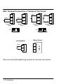
1
AC INVERTER Series 10 Inverter Control Installation and Operating Manual 6/98 MN710 Table of Contents Section 1 General Information . . . . . . . . . . . . . . . . . . . . . . . . . . . . . . Limited Warranty . . . . . . . . . . . . . . . . . . . . . . . . . . . . . . . . Safety Notice . . . . . . . . . . . . . . . . . . . . . . . . . . . . . . . . . . . Precautions . . . . . . . . . . . . . . . . . . . . . . . . . . . . . . . . . . Specifications . . . . . . . . . . . . . . . . . . . . . . . . . . . . . . . . . . Watts Loss Data . . . . . . . . . . . . . . . . . . . . . . . . . . . . . . Ratings . . . . . . . . . . . . . . . . . . . . . . . . . . . . . . . . . . . . . . Section 2 Installation . . . . . . . . . . . . . . . . . . . . . . . . . . . . . . . . . . . . . . Location and Mounting . . . . . . . . . . . . . . . . . . . . . . . . . . . Terminal Access Cover Removal . . . . . . . . . . . . . . . . . . Terminal and Jumper Locations . . . . . . . . . . . . . . . . . . . Wiring Considerations . . . . . . . . . . . . . . . . . . . . . . . . . . . Wire Size and Protection Devices . . . . . . . . . . . . . . . Recommended Terminal Tightening Torques . . . . . Main Circuit Wiring . . . . . . . . . . . . . . . . . . . . . . . . . . . . . . AC Power Connections . . . . . . . . . . . . . . . . . . . . . . . . Motor Connections . . . . . . . . . . . . . . . . . . . . . . . . . . . . Motor Connections . . . . . . . . . . . . . . . . . . . . . . . . . . . . . . Logic Wiring . . . . . . . . . . . . . . . . . . . . . . . . . . . . . . . . . . . . Analog Command Inputs . . . . . . . . . . . . . . . . . . . . . . . Analog Output . . . . . . . . . . . . . . . . . . . . . . . . . . . . . . . . Opto Isolated Inputs . . . . . . . . . . . . . . . . . . . . . . . . . . . External Trip Connection . . . . . . . . . . . . . . . . . . . . . . . Jumper J19 Input Selection . . . . . . . . . . . . . . . . . . . . Relay Outputs . . . . . . . . . . . . . . . . . . . . . . . . . . . . . . . . 1-1 1-1 1-2 1-2 1-4 1-6 1-7 2-1 2-1 2-2 2-3 2-3 2-5 2-6 2-6 2-7 2-8 2-8 2-10 2-10 2-11 2-11 2-11 2-12 2-13 Table of Contents i Selection Of Operation Mode And Connection Diagrams 2-13 2 Wire Run/Stop Connections . . . . . . . . . . . . . . . . . . 2-14 3 Wire Run/Stop Connections . . . . . . . . . . . . . . . . . . 2-16 2 Wire Run/Stop, Electronic Potentiometer Connections . . . 2-17 3 Wire Run/Stop, Electronic Potentiometer Connections . . . 2-17 MOL Terminal Connections . . . . . . . . . . . . . . . . . . . . . 2-18 Pre-Operation Checks . . . . . . . . . . . . . . . . . . . . . . . . . . . 2-20 Check of Electrical Items . . . . . . . . . . . . . . . . . . . . . . . 2-20 Check of Motors/Couplings . . . . . . . . . . . . . . . . . . . . . 2-20 Temporary Application of Power . . . . . . . . . . . . . . . . 2-21 Pre-Operation Check List . . . . . . . . . . . . . . . . . . . . . . 2-21 Section 3 Operation . . . . . . . . . . . . . . . . . . . . . . . . . . . . . . . . . . . . . . . . 3-1 Keypad Key Functions . . . . . . . . . . . . . . . . . . . . . . . . . . . 3-1 Keypad Status Indicator . . . . . . . . . . . . . . . . . . . . . . . . . . 3-3 Description of Keypad Displays . . . . . . . . . . . . . . . . . . . 3-4 Stop Mode . . . . . . . . . . . . . . . . . . . . . . . . . . . . . . . . . . . 3-5 Run Mode . . . . . . . . . . . . . . . . . . . . . . . . . . . . . . . . . . . 3-5 Program Mode . . . . . . . . . . . . . . . . . . . . . . . . . . . . . . . 3-6 Security Access/Lockout . . . . . . . . . . . . . . . . . . . . . . . 3-6 Control Operation Adjustment . . . . . . . . . . . . . . . . . . . . 3-6 Level One Parameter Adjustments . . . . . . . . . . . . . . . . 3-7 07-Last Fault . . . . . . . . . . . . . . . . . . . . . . . . . . . . . . . . . 3-7 12-Output Frequency . . . . . . . . . . . . . . . . . . . . . . . . . . 3-7 13-Output Voltage . . . . . . . . . . . . . . . . . . . . . . . . . . . . . 3-7 14-Output Current . . . . . . . . . . . . . . . . . . . . . . . . . . . . . 3-7 15-Drive Load . . . . . . . . . . . . . . . . . . . . . . . . . . . . . . . . 3-7 ii Table of Contents 16-Load Torque . . . . . . . . . . . . . . . . . . . . . . . . . . . . . . . 17-Heatsink Temp . . . . . . . . . . . . . . . . . . . . . . . . . . . . . 21-Operating Mode . . . . . . . . . . . . . . . . . . . . . . . . . . . 31-Min Output Frequency . . . . . . . . . . . . . . . . . . . . . 32-Max Output Frequency . . . . . . . . . . . . . . . . . . . . . 42-Accel Time #1 . . . . . . . . . . . . . . . . . . . . . . . . . . . . . 43-Decel Time #1 . . . . . . . . . . . . . . . . . . . . . . . . . . . . . 52-Torque Boost . . . . . . . . . . . . . . . . . . . . . . . . . . . . . . 65-Slip Comp Adj . . . . . . . . . . . . . . . . . . . . . . . . . . . . . 67-Timed Overload Trip . . . . . . . . . . . . . . . . . . . . . . . . 70-Analog Output Scale . . . . . . . . . . . . . . . . . . . . . . . 71-Analog Output Select . . . . . . . . . . . . . . . . . . . . . . . 75-Relay Output Select . . . . . . . . . . . . . . . . . . . . . . . . Level Two Parameter Adjustments . . . . . . . . . . . . . . . . 02-Software Revision . . . . . . . . . . . . . . . . . . . . . . . . . . 03-Rated Current . . . . . . . . . . . . . . . . . . . . . . . . . . . . . 08-Second Fault . . . . . . . . . . . . . . . . . . . . . . . . . . . . . . 09-First Fault . . . . . . . . . . . . . . . . . . . . . . . . . . . . . . . . . 24-Analog Command Select . . . . . . . . . . . . . . . . . . . . 33-Preset Speed #1 . . . . . . . . . . . . . . . . . . . . . . . . . . . 34-Preset Speed #2 . . . . . . . . . . . . . . . . . . . . . . . . . . . 35-Preset Speed #3 . . . . . . . . . . . . . . . . . . . . . . . . . . . 36-Preset Speed #4 . . . . . . . . . . . . . . . . . . . . . . . . . . . 37-Preset Speed #5 . . . . . . . . . . . . . . . . . . . . . . . . . . . 38-Preset Speed #6 . . . . . . . . . . . . . . . . . . . . . . . . . . . 39-Min Freq Torque Limit . . . . . . . . . . . . . . . . . . . . . . 41-Accel/Decel/Coast Select . . . . . . . . . . . . . . . . . . . 44-Accel Time #2 . . . . . . . . . . . . . . . . . . . . . . . . . . . . . 3-7 3-7 3-8 3-9 3-9 3-9 3-9 3-10 3-10 3-11 3-11 3-12 3-12 3-13 3-13 3-13 3-13 3-13 3-14 3-14 3-14 3-15 3-15 3-15 3-15 3-15 3-16 3-17 Table of Contents iii 45-Decel Time #2 . . . . . . . . . . . . . . . . . . . . . . . . . . . . . 46-Decel Time Torque Limit . . . . . . . . . . . . . . . . . . . . 47-DC Brake Time . . . . . . . . . . . . . . . . . . . . . . . . . . . . 48-DC Brake Voltage . . . . . . . . . . . . . . . . . . . . . . . . . . 51-V/HZ Profile . . . . . . . . . . . . . . . . . . . . . . . . . . . . . . . 53-Control Base Frequency . . . . . . . . . . . . . . . . . . . . 59-Max. Output Volts . . . . . . . . . . . . . . . . . . . . . . . . . . 61-Load Torque Limit FWD . . . . . . . . . . . . . . . . . . . . . 62-Load Torque Limit REV . . . . . . . . . . . . . . . . . . . . . 63-Regen Torque Limit FWD . . . . . . . . . . . . . . . . . . . 64-Regen Torque Limit REV . . . . . . . . . . . . . . . . . . . . 68-Number of Restarts . . . . . . . . . . . . . . . . . . . . . . . . 69-Restart Delay . . . . . . . . . . . . . . . . . . . . . . . . . . . . . . 77-External Trip Select . . . . . . . . . . . . . . . . . . . . . . . . 81-Factory Settings . . . . . . . . . . . . . . . . . . . . . . . . . . . 82-Start Options . . . . . . . . . . . . . . . . . . . . . . . . . . . . . . Auto Restart . . . . . . . . . . . . . . . . . . . . . . . . . . . . . . . . . . Synchro Starts . . . . . . . . . . . . . . . . . . . . . . . . . . . . . . . . 84-Display Options . . . . . . . . . . . . . . . . . . . . . . . . . . . . 87-Security Access Code . . . . . . . . . . . . . . . . . . . . . . Section 4 Troubleshooting . . . . . . . . . . . . . . . . . . . . . . . . . . . . . . . . . . . Diagnostic Displays . . . . . . . . . . . . . . . . . . . . . . . . . . . . . Maintenance . . . . . . . . . . . . . . . . . . . . . . . . . . . . . . . . . . . Troubleshooting . . . . . . . . . . . . . . . . . . . . . . . . . . . . . . . . . Section 5 Illustrations . . . . . . . . . . . . . . . . . . . . . . . . . . . . . . . . . . . . . . . Appendix A Parameters . . . . . . . . . . . . . . . . . . . . . . . . . . . . . . . . . . . . . . . iv Table of Contents 3-17 3-17 3-17 3-18 3-19 3-20 3-20 3-20 3-21 3-21 3-21 3-21 3-21 3-22 3-23 3-23 3-23 3-24 3-25 3-26 4-1 4-1 4-3 4-3 5-1 A-1 Section 1 General Information Limited Warranty For a period of two (2) years from the date of original purchase, BALDOR will repair or replace without charge controls which our examination proves to be defective in material or workmanship. This warranty is valid if the unit has not been tampered with by unauthorized persons, misused, abused, or improperly installed and has been used in accordance with the instructions and/or ratings supplied. This warranty is in lieu of any other warranty or guarantee expressed or implied. BALDOR shall not be held responsible for any expense (including installation and removal), inconvenience, or consequential damage, including injury to any person or property caused by items of our manufacture or sale. (Some states do not allow exclusion or limitation of incidental or consequential damages, so the above exclusion may not apply.) In any event, BALDOR’s total liability, under all circumstances, shall not exceed the full purchase price of the control. Claims for purchase price refunds, repairs, or replacements must be referred to BALDOR with all pertinent data as to the defect, the date purchased, the task performed by the control, and the problem encountered. No liability is assumed for expendable items such as fuses. Goods may be returned only with written notification including a BALDOR Return Authorization Number and any return shipments must be prepaid. General Information 1-1 Safety Notice This equipment contains voltages that may be as great as 800 volts! Electrical shock can cause serious or fatal injury. Only qualified personnel should attempt the start-up procedure or troubleshoot this equipment. This equipment may be connected to other machines that have rotating parts or parts that are driven by this equipment. Improper use can cause serious or fatal injury. Only qualified personnel should attempt the start-up procedure or troubleshoot this equipment. PRECAUTIONS WARNING: Do not touch any circuit board, power device or electrical connection before you first ensure that power has been disconnected and there is no high voltage present from this equipment or other equipment to which it is connected. Electrical shock can cause serious or fatal injury. Only qualified personnel should attempt the start-up procedure or troubleshoot this equipment. WARNING: Be sure that you are completely familiar with the safe operation of this equipment. This equipment may be connected to other machines that have rotating parts or parts that are controlled by this equipment. Improper use can cause serious or fatal injury. Only qualified personnel should attempt the start-up procedure or troubleshoot this equipment. 1-2 General Information WARNING: Be sure the system is properly grounded before applying power. Do not apply AC power before you ensure that all grounding instructions have been followed. Electrical shock can cause serious or fatal injury. WARNING: Do not remove cover for at least five (5) minutes after AC power is disconnected to allow capacitors to discharge. Dangerous voltages are present inside the equipment. Electrical shock can cause serious or fatal injury. WARNING: Improper operation of control may cause violent motion of the motor shaft and driven equipment. Be certain that unexpected motor shaft movement will not cause injury to personnel or damage to equipment. Peak torque of several times the rated motor torque can occur during control failure. WARNING: Motor circuit may have high voltage present whenever AC power is applied, even when motor is not rotating. Electrical shock can cause serious or fatal injury. WARNING: This unit has an automatic restart feature that will start the motor whenever input power is applied and a RUN (FWD or REV) command is issued and maintained. If an automatic restart of the motor could cause injury to personnel, the automatic restart feature should be disabled by changing the AUTORESTART parameter 82 to MANUAL. General Information 1-3 Specifications Horse Power 0.5 - 1 HP @ 115VAC, 1PH 0.5 - 5 HP @ 230VAC, 3PH 1 - 5 HP @ 460VAC, 3PH Input Voltage 95 - 127 VAC, 50/60Hz, Single Phase 187 - 253VAC, 50/60Hz, Three Phase 342 - 506VAC, 50/60Hz, Three Phase ±2% Phase Imbalance (3Phase Only) Input Frequency Enclosure 50/60Hz (±10%) NEMA 1 Output Voltage 0 to Maximum Input AC Voltage Output Frequency Output Current 0.1 to 400 Hz See Control Rating Table Service Factor 1.0 Duty Cycle Continuous Overload Capacity See Control Rating Table Control Method Carrier Frequency Voltage Vector PWM 9.2kHz Frequency Resolution V/Hz Ratio 0.05Hz 0.24 - 8.85 (230VAC) 0.48 - 17.69 (460VAC) IGBT (Insulated Gate Bipolar Transistor) Output Transistor Type Transistor Rise Time Torque Boost 2500Volts/msec (dv/dt) Standard (automatic adjustment to load) Manual (0-15% of input voltage) Volts/Hertz Pattern Accel/Decel Time Linear to Squared Reduced (in 6 patterns) 0.1 to 600 seconds (for 2 assignable) Base Frequency 26 to 960 Hz Dynamic Brake Torque Up to 60% for 6 seconds 1-4 General Information Auto Restart Manual or Automatic Min. Output Frequency Max. Output Frequency 0.1 to 400Hz 20 to 400Hz Slip Compensation 0 to 12% Opto Input Impedance 4.5 k Ohms Ambient Temperature Humidity 0°C to 40°C (Maximum without derating) 90% Maximum RH non-condensing Altitude 3300 Ft. (Maximum without derating) Frequency Setting Keypad, 0-5VDC, 0-10VDC, 0-20mA Frequency Setting Pot. 5k Ohm, 0.5 Watt Operating Modes Keypad, 2 Wire, 3 Wire, Preset Speeds, Electronic Potentiometer Vibration Agency Listings 0.6G Maximum UL and cUL Listed General Information 1-5 Operator Keypad Display Keypad Functions Custom Backlit LCD 8 Key with Tactile Feel Output Status Monitoring, Digital Speed Control, Parameter Setting and Display and Fault Log Display Red/Green for Status LED Indicators Analog Outputs Analog Outputs Full Scale Range Output Conditions 1 Assignable 0 to 10VDC Maximum 3 conditions plus calibration (see Analog Output Table) Relay Outputs Relay Outputs Rated Voltage Rated Current Conditions 1 Assignable 115VAC 1 Ampere Maximum 10 conditions (see Relay Output Table) Fault Conditions Automatic Shutdown 15 conditions (see Fault Code Table) Watts Loss Data Catalog No. ID101F50-E ID10101-E ID102F50-E ID10201-E ID10202-E ID102 ID102 ID10401-E ID10402-E ID104 ID104 Horsepower Inputt Inp Voltage 0.5 1PH 1.0 1PH 0.5 3PH 1.0 3PH 2.0 3PH 3.0 3PH 5.0 3PH 1.0 3PH 2.0 3PH 3.0 3PH 5.0 3PH 115 115 230 230 230 230 230 460 460 460 460 1-6 General Information Total Watts Loss Single Phase Three Phase Input Input 24 N/A 42 N/A 16 19 28 37 52 66 66 70 70 129 N/A 40 N/A 67 N/A 118 N/A 184 Ratings Catalog g No. ID101F50-E ID10101-E ID102F50-E ID10201-E ID10202-E ID10203-E ID10205-E ID10401-E ID10402-E ID10403-E ID10405-E * HP (kW) 0.5 (0.37) 1.0 (0.75) 0.5 (0.37) 1.0 (0.75) 2.0 (1.5) 3.0 (2.2) 5.0 (3.7) 1.0 (0.75) 2.0 (1.5) 3.0 (2.2) 5.0 (3.7) VAC Input Amps Output Amps Cont * 2.2 Amps Peak 3.3 115 4.5 Volts VAC 230 115 8.9 230 4.0 6.0 230 1.9 230 2.2 3.3 230 3.8 230 4.0 6.0 230 7.5 230 7.5 11.3 230 10.4 230 10.6 15.9 230 17.6 230 16.7 25.1 460 2.3 460 2.2 3.3 460 5.1 460 4.1 6.2 460 6.2 460 6.1 9.2 460 10.8 460 9.9 14.9 Rating equals 1.1 times parameter 03-Rated Current value. Note: 230VAC three phase units can be operated at 115VAC single phase power if the output current AMPS (Continuous and Peak) are derated by 25%. General Information 1-7 1-8 General Information Section 2 Installation This section describes the proper mounting and wiring of the BALDOR Series 10 Inverter. If problems arise, please refer to the troubleshooting information located in Section 4. Location and Mounting Select a mounting surface for the inverter that will allow the control to be mounted in a vertical position using the four mounting holes provided. The area selected should allow for free air circulation around the control. Provide for at least five inches of clearance on all sides for maximum cooling efficiency. Caution: Avoid locating the inverter immediately above or beside heat generating equipment, or directly below water or steam pipes. The ambient temperature around the control should not exceed 40°C. If the control is mounted into an existing control cabinet, the ambient temperature limits should not be exceeded or failure of the control may result. In cases where extreme temperatures are unavoidable, a separate blower fan or cooling system should be considered. Please contact the factory for derating of controls operated in temperatures above 40°C. The standard ventilated NEMA 1 enclosure should not be used in areas where the control will be subjected to liquids, chemicals, large amounts of airborne material (i.e. dust or lint), or explosive atmospheres. Appropriate protection should be provided for the inverter when used in these environments. If the control will be subjected to levels of vibration above 0.6G, then the inverter should be shock mounted. Excessive vibration within the control could cause internal connections to loosen and cause component failure or electrical shock hazard. Installation 2-1 Terminal Access Cover Removal To remove the Terminal Access Cover insert a small blade screwdriver into the slots located on the lower left and right hand corners of the access cover. Use a slight twisting motion while lifting upward to loosen one side. Use the same motion to loosen the other side then lift the cover off of the control. To reinstall, simply snap the cover back into place. See Figure 2-1 below. Figure 2-1 2-2 Installation Terminal and Jumper Locations Figure 2-2 shows the location of the power terminal strip , control terminal strip , ground lug, and user adjustable jumper locations. Only motor and input power should be connected to the power terminal strip. Motor ground and input power earth ground should be connected to the ground lug. Only external control wiring should be connected to control terminal strip. Figure 2-2 Terminal and Jumper Locations J19 AC Line L1, L2, L3 Control Terminals Motor M1, M2, M3 Wiring Considerations Interconnection wiring is required between the motor control, AC power source, motor, host control and any operator interface stations. Use listed closed loop connectors that are of appropriate size for wire gauge being used. Connectors are to be installed using crimp tool specified by the manufacturer of the connector. Only Class 1 wiring should be used. Installation 2-3 Caution: Separate over-current protection may be required by the National Electrical Code. The installer of this equipment is responsible for complying with the National Electrical Code and any applicable local codes which govern such practices as wiring protection, grounding, disconnects, and other current protection. The inverter is self protected from normal AC line transients and surges. Additional external protection may be required if high energy transients are present on the incoming power source. These transients could be caused by sharing a power source with arc welding equipment, large motors being started across the line, or other industrial equipment requiring large surge currents. To prevent inverter damage due to power source disturbances the following should be considered: 1. 2. 3. Connect the inverter on a feeder line separate from those supplying large inductive loads. Supply power to the inverter through a suitably sized isolation transformer. When using an isolation transformer to power the inverter, always switch the power off and on between the transformer secondary and the inverter input to avoid spikes at the inverter when power is removed from the primary side. Supply power to the inverter through a suitably sized line reactor. Line reactors serve several purposes: 4. A. B. C. Minimize voltage spikes from the power line that may cause the inverter to trip on over-voltage. Minimize voltage harmonics from the inverter to the power line. Provide additional short circuit capability at the inverter. 2-4 Installation Caution: Do not use power factor correction capacitors on the input power lines to the inverter or damage to the control may result. All external control wiring to the inverter should be run in a separate conduit from all other wiring. The use of shielded twisted pair wire is recommended for all control wiring. The shield of the control wiring should be connected to control terminal CM of the inverter only. The other end of the shield should be taped to the wire jacket to prevent electrical shorts. Conduit openings are provided at the bottom of the inverter housing to allow power and control wiring entrance to the control. Please refer to the inverter outline drawings located in Section 5 of this manual for sizes of the conduit openings. The following tables show recommended wire size and protection devices along with recommended terminal tightening torques. Wire Size and Protection Devices Catalog No No. ID101F50-E ID10101-E ID102F50-E ID10201-E ID10202-E ID10203-E ID10205-E ID10401-E ID10402-E ID10403-E ID10405-E Rated HP Input/ Output Wire AWG Cu C 0.5 1 0.5 1 2 3 5 1 2 3 5 14 14 14 14 14 14 12 14 14 14 14 Input Fuses Input Breaker 240V/10A 240V/15A 240V/10A 240V/15A 240V/20A 240V/25 240V/40 480V/5A 480V/10A 480V/15 480V/20 Fast Time Acting 240V/5A 240V/10A 240V/5A 240V/10A 240V/20A 240V/25 240V/35 480V/5A 480V/10A 480V/15 480V/20 Delay 240V/3A 240V/6A 240V/3A 240V/6A 240V/12A 240V/15 240V/25 480V/6A 480V/12A 480V/15 480V/25 Input and output wire size is based on use of 60/75°C rated copper conductor wire. Installation 2-5 Recommended Terminal Tightening Torques Catalog g No. All Series 10 Caution: Tightening Torques Power Terminal TB1 Control Terminal Strip 10 In-Lb (1.13 Nm) 2 In-Lb (0.23 Nm) Do not use this control with any input voltage other than stated on the control nameplate. Use of control with wrong power source can damage the control. Main Circuit Wiring External or remote motor overload protection may be required by NEC or other regulator codes. To External Trip Circuit Motor M3 T3 T2 T1 M2 M1 GND L3 * L2 L1 Heatsink GND 50/60Hz 3 Phase Power Breaker or Fuse Protection customer provided option Heatsink GND * Note: L3 is not available on 115VAC input models. See recommended tightening torques for terminal connectors. 2-6 Installation AC Power Connections Connect the fused three phase AC power lines to the input power terminals L1, L2, and L3. The phase rotation of the input power is not important since the control is not sensitive to phase rotation of the input power. For single phase AC power connect to input power terminals L1 and L2. Connect an earth ground to the inverter according to any applicable electrical code. The earth ground should be connected to the inverter chassis ground screw. The use of a power disconnect is recommended between the input power and the inverter to provide a fail safe method to disconnect the inverter from the input power. The inverter will remain in a power up condition until all input power is removed from the control and the internal bus voltage is depleted. Caution: Do not attempt to service this equipment while bus voltage is present within the inverter. Remove input power and wait at least 5 minutes for the residual power in the bus capacitors to dissipate. Caution: This unit has an automatic restart feature that will start the motor whenever input power is applied and a maintained external run (FWD or REV) command is present at the control. If an automatic restart of the motor could cause personal injury or harm, the auto restart feature should be defeated with external control wiring or by adjusting parameter 82-Start Options. Installation 2-7 Motor Connections Connect the three phase power leads of the AC motor to terminals M1, M2, and M3 of the inverter power terminal strip. The motor ground lead or case ground should be connected to the inverter chassis ground screw. The motor should be connected to the inverter at all times during inverter operation. If additional motor overload protection is required, the use of suitably sized motor overload relays are recommended. Motor overload relays should be connected between the motor and inverter with the relay trip indicator circuit connected into the external inverter control circuitry to power down or trip the inverter in the event of motor overloading. Caution: Overload relays with an automatic reset feature are not recommended in applications where an automatic restart of the motor could cause personal injury or harm. If manual reset relays are not available, then the automatic reset feature should be defeated. If the motor is equipped with a normally closed thermostat, the thermostat should be connected at terminals MOL and CM of the control terminal strip. The inverter will also need to be programmed to trip if this thermostat circuit opens indicating a motor overload condition. The inverter will need to be programmed by adjusting parameter 77-External Trip Select and placing the proper jumper position on jumper terminals J19. If during initial motor start up the motor rotation is opposite to that desired, disconnect the input power from the inverter and wait at least 5 minutes for the bus voltage to bleed off. Interchange any two of the three motor leads at the inverter power terminal strip M1, M2, and M3 to change the shaft rotation of the motor. 2-8 Installation M-Contactor If required by local codes or for safety reasons, an M-Contactor (motor circuit contactor) may be installed. However, incorrect installation or failure of the M-Contactor or wiring may damage the control. Caution: If an M-Contactor is installed, the control must be disabled at least 20msec before the M-Contactor is opened. If the M-Contactor is opened while the control is supplying voltage and current to the motor, the control may me damaged. A motor circuit contactor provides a positive disconnect of the motor windings from the control. Opening the M-Contactor ensures that the control cannot drive the motor. This may be required during certain manual operations with the load (like cleaning cutting knives etc.). Figure 2-3 shows how an M-Contactor is connected to the H series control. Figure 2-3 Typical Connections for M-Contactor Stop/E-Stop M M3 M2 M Motor M1 See recommended tightening torques for terminal connectors. Installation 2-9 Logic Wiring All logic and control connections are made at the control terminal strip located on the motor control board. Screw type terminals are provided for easy connection to your external control station and meters. The control terminal strip can be divided into four major categories as follows: 1) Analog command inputs. 2) Analog outputs. 3) Opto Isolated inputs. 4) Relay outputs. Analog Command Inputs An external 5kohm potentiometer can be connected at terminals CM, VIN, and REF. The potentiometer should be connected so that full resistance is connected from CM and REF. REF is a 5VDC potentiometer reference output. The wiper of the potentiometer should be connected at terminal VIN. The speed command input will be recognized at terminals CM and VIN. When using a potentiometer as the speed command, the Analog Command Select parameter will need to be programmed to 0 or 1 and jumper J19 will need to be set properly. An external speed command of 0-5VDC, 0-10VDC, 0-20 mA, or 4- 20mA can be used instead of a potentiometer at terminals CM and VIN. The positive lead should be connected at terminal VIN and the negative lead should be connected at terminal CM. The Analog Command Select parameter should also be programmed to 0 or 1 and jumper J19 will need to be set properly. 2-10 Installation Analog Output One programmable analog output is available for external monitoring of the drive condition. This output is available at terminals CM and MET. The output will be 0-10VDC. The positive lead of the external meter should be connected to terminal MET and the negative lead should be connected at terminal CM. The output condition is programmed in parameter 71-Analog Output Select. The analog output gain (max output voltage) can be adjusted in parameter 70- Analog Output Scale. Please refer to the Analog Output Table in Section 3 for the possible monitoring conditions. Opto Isolated Inputs Six digital inputs are available at terminals FWD, REV, PS3, PS2, PS1, and MOL to command various output conditions. The available command condition at the terminal may change depending on the operating mode selected. These inputs can be configured for Pull- Up or Pull-Down Logic. The factory setting is for Pull-Up Logic. The Inputs will be active when connected to terminal V+ or when utilizing an external 0-24 VDC power supply with the power supply common connected to terminal CM. The selection of Pull-UP or Pull-Down Logic is set by jumper J19. Depending on the function of the command input, a maintained switch closure or momentary switch closure will be required. Connection to a PLC, CNC, or host computer are also possible. External Trip Connection Terminal MOL is available for connection to a normally open or normally closed thermostat in all operating modes. This connection is available for connection to a motor thermostat or overload relay. The thermostat or overload relay input can also be configured for Pull-Up or Pull-Down Logic. If the state of the motor thermostat or overload relay should ever change indicating an over-temperature condition, the inverter will automatically shut down and give an External Trip fault (F07) or will cause the Installation 2-11 motor to coast to a stop. The fault or coast to stop operation of the MOL input terminal is selected by parameter 77-External Trip Select. The selection of pull- up or pull-down logic is set by jumper J19. Jumper J19 Input Selection Jumper J19 is a pin-jumper selector located to the left and below the control terminal strip (See Figure 2-2). Five jumper positions are available and are arranged in one group of three positions and one group of two positions with one shorting jumper in each group. The group of two located to the right hand side are used to select the active state of the opto isolated inputs (Pull-Up or Pull-down Logic). The group of three located to the left hand side are used to select the type of analog speed command signal to be used. The available analog speed command signals are 0-5VDC, 0-10VDC, 0-20 mA, and 4-20 mA. A 5kohm 1/2 watt potentiometer can be used by configuring for 0-5VDC. The available jumper settings are shown in the following diagram: Jumper J19 Selections Analog speed OPTO isolated command settings input settings * * " * * " $$ $" $ ") $$ Caution: 2-12 Installation %* ' !%$# " $& ' $ $ $" %*%! !%$# " $& ' $ $ $" " ($" * #%!!) '$ $# $ $ * $& * $& $ ") $$ Remove input power and wait at least 5 minutes for the residual power in the bus capacitors to dissipate before changing the J19 jumper positions. Relay Outputs Programmable relay outputs are available for external monitoring of the drive condition. These outputs are available at terminals NO (Normally Open) and NC (Normally Closed) with a common at terminal RCM (Relay Common). The circuit must be completed by connection at terminals NO or NC and returned to RCM. The output condition for terminals NO and NC is programmed in parameter 75- Relay Output Select. The relay outputs are rated at 115 VAC and 1 Amp maximum. Selection Of Operation Mode And Connection Diagrams Several operating modes are available within the Series 10 inverter. These operating modes define the basic operation of the input terminal configurations and motor control setup. The operating modes are selected by the setting of jumper J19, and programming of parameters 21-Operating Mode, 24-Analog Command Select, 41- Accel/Decel/Coast Select, and 77-External Trip Select. These functions are briefly shown below. For a more detailed discussion please refer to Section 3 of this manual. 0-10VDC External Speed Reference 0-5VDC External Speed Reference Speed Potentiometer Current Reference See recommended tightening torques for terminal connectors. Installation 2-13 2 Wire Run/Stop Connections Parameter 21 - Operating Mode = 2 or 3 Parameter 41 - Accel/Decel/Coast select = 0, 1, 2, 4, 5 or 6 J19 Pull–Up Logic J19 Pull–Down Logic See recommended tightening torques for terminal connectors. Speed Select PS3 PS2 Open Open Open Open Open Closed Closed Closed Closed Open Closed Closed Open Open Closed Closed 2-14 Installation PS1 Open Closed Open Closed Open Closed Open Closed Function Keypad or Analog Command Input 33 - Preset Speed #1 34 - Preset Speed #2 35 - Preset Speed #3 36 - Preset Speed #4 37 - Preset Speed #5 38 - Preset Speed #6 32 - Max Output Frequency 2 Wire Run/Stop Connections Parameter 21 - Operating Mode = 2 or 3 Parameter 41 - Accel/Decel/Coast select = 3 or 7 J19 Pull–Up Logic J19 Pull–Down Logic See recommended tightening torques for terminal connectors. Speed Select PS2 PS1 Open Open Open Closed Closed Function Keypad or Analog Command Input Closed 33 - Preset Speed #1 Open 34 - Preset Speed #2 Closed 35 - Preset Speed #3 Ramp Select Function PS3 Open 42 - Accel Time #1 Active Closed 43 - Decel Time #1 Active Open 44 - Accel Time #2 Active Closed 45 - Decel Time #2 Active Installation 2-15 3 Wire Run/Stop Connections Parameter 21 - Operating Mode = 4 or 5 J19 Pull–Up Logic J19 Pull–Down Logic See recommended tightening torques for terminal connectors. Speed Select PS2 PS1 Open Open Open Closed Closed Function Keypad or Analog Command Input Closed 33 - Preset Speed #1 Open 34 - Preset Speed #2 Closed 35 - Preset Speed #3 2-16 Installation 2 Wire Run/Stop, Electronic Potentiometer Connections Parameter 21 - Operating Mode = 6 " ! J19 " ! J19 Pull–Up Logic Pull–Down Logic 3 Wire Run/Stop, Electronic Potentiometer Connections Parameter 21 - Operating Mode = 7 " ! J19 Pull–Up Logic " ! J19 Pull–Down Logic See recommended tightening torques for terminal connectors. Installation 2-17 MOL Terminal Connections (77-External Trip Select) J19 J19 Pull–Up Logic Pull–Down Logic Analog Meter Relay Output See recommended tightening torques for terminal connectors. 2-18 Installation Jumper J19 - Used to select the active state of the opto isolated inputs (Pull-Up or Pull-down Logic) and to select the type of analog speed command signal to be applied. The available analog speed command signals are 0-5 VDC, 0-10 VDC, 0-20 mA, and 4-20 mA. A 5kohm 1/2 Watt Potentiometer can be used by configuring for 0-5 VDC. 21-Operating Mode - Defines the source for speed reference command and RUN/STOP control inputs. 24-Analog Command Select - Defines the type of external speed reference command and if the command is accepted as a direct command or inverted command. 41-Accel/Decel/Coast Select - Selects which Accel and Decel Time parameters are applied to the control output and also defines if Coast to Stop is active after a STOP command. 77-External Trip Select - Defines if a normally open or normally closed contact at control terminal MOL will generate an External Trip Fault (F07) or a Coast to Stop condition. 82-Start Options - Sets the operation of Auto Restart and Synchro Starts. Also enables or disables the STOP key as an E-Stop when operating from the control terminal strip and the Stop function due to a disconnection of an external command line connected at the control terminal strip. Installation 2-19 Pre-Operation Checks Check of Electrical Items After completing all the installation steps and before applying line power to the system, carefully check the following items: 1. 2. 3. 4. Verify AC line voltage at source matches control rating. Inspect all power terminations for workmanship and tightness. Verify control and motor are grounded to each other and the control is connected to earth ground. Check incoming signal wiring for accuracy. Be certain all brake coils, contactors, and relay coils have noise suppression. This should be an R-C filter for AC coils and reverse polarity diodes for DC coils. MOV type transient suppression is not adequate. WARNING: MAKE SURE THAT UNEXPECTED OPERATION OF THE MOTOR SHAFT DURING START-UP WILL NOT CAUSE INJURY TO PERSONNEL OR DAMAGE TO EQUIPMENT. Check of Motors/Couplings Verify freedom of motion for all motor shafts and that all motor couplings are tight without backlash. Verify the holding brakes, if any, are properly adjusted to fully release and set to the desired torque value. 2-20 Installation Temporary Application of Power Double check electrical and mechanical connections before applying power to the control. Temporarily apply power and observe that the display is on. If this indication doesn’t occur, double check all connections and verify input voltage. If the display still is not on, refer to the troubleshooting table in Section 4. Pre-Operation Check List 1) 2) 3) 4) 5) 6) 7) Verify jumper J19 settings. Verify 21-Operating Mode setting. Verify 24-Analog Command Select settings. Verify 41-Accel/Decel/Coast Select settings. Verify 77-External Trip Select settings. Verify 82-Start Options settings. Review Section 3 of this manual for more detailed information on parameter adjustments and their affects on motor operation. Installation 2-21 2-22 Installation Section 3 Operation Keypad Key Functions The programming and basic operation of the Series 10 Inverter is accomplished by simple keystrokes on the operator control panel. The function of the keys are as follows: Operation 3-1 STOP Push to initiate a stop command. Depending on the setup of the control the motor will either ramp (Regen) or Coast to Stop. See 41-Accel/Decel/Coast Select in Section 3 for more information. FWD Used to initiate a forward direction run of the motor. REV Used to initiate a reverse direction run of the motor. PROG Used to access Level 1 Parameters. Holding the SHIFT key then pressing the PROG key will access Level 2 Parameters. If in the Run Mode the control will only allow viewing of the parameter values. Any attempt to change a parameter value while in the Run Mode will result in the display showing “-----”. If in the Stop Mode pressing PROG or holding SHIFT then pressing PROG will enter the Programming Mode at Level 1 and Level 2 Parameters respectively. Pressing the PROG key while in the Programming Mode will return the control to the Stop Mode. SHIFT Used in the Program Mode to allow changing of a parameter value. While in Program Mode, the factory preset value may be reset for any parameter by pressing the SHIFT key then the UP and DOWN ARROW keys simultaneously. The New parameter value is stored when the ENTER key is pressed. UP ARROW Used to change the displayed parameter or parameter value up one increment. In the Programming Mode the displayed parameters or parameter values will increment up until the highest possible value is reached. The UP Arrow is also used to increment the set speed in the Stop Mode and increment the actual speed in the Run Mode. The value will increase at a faster rate after holding the UP Arrow key for 5 seconds. Pressing SHIFT while holding the UP Arrow will bypass the 5 second delay. DOWN ARROW Used to change the displayed parameter or parameter value down one increment. In the Programming Mode the displayed parameters or parameter values will increment down until the lowest possible value is reached. The DOWN 3-2 Operation Arrow is also used to decrement the set speed in the Stop Mode and decrement the actual speed in the Run Mode. The value will decrease at a faster rate after holding the DOWN Arrow key for 5 seconds. Pressing SHIFT while holding the DOWN Arrow will bypass the 5 second delay. ENTER Used to store a new parameter value when in the Programming Mode. Also used in the Run and Stop Modes to store the current output frequency as the initial output frequency when power is applied to the inverter. Keypad Status Indicator The STATUS indicator consists of two LED’s, one green and one red. They are visible through a lens in the upper right hand corner of the keypad. The following table defines the STATUS indicator state for the various operating conditions of the inverter. OPERATING CONDITION STATUS INDICATION Continuous displays Green and Red Power on, Restart (2 Seconds) Red Stop, Running in Torque Limit Green Run Intermittent Displays Alternate Green and Running in and out of Torque Limit Red Blinking Green Blinking Running in and out of an Overvoltage or Undervoltage condition Red Blinking Fault Condition, Emergency Stop, Auto Restart Lock-out, Low Voltage Operation 3-3 Description of Keypad Displays The custom, back-lit, LCD display provides information on drive operation and programming. The four large 7-segment displays show inverter output and programming data. Two smaller 7-segment displays are used to indicate parameter numbers. Special symbols and displays provide further clarification of drive operation. In normal operation only those segments that are active are displayed. The following figure shows all segments displayed. The following table lists the special symbols and their meaning. 3-4 Operation Symbol FWD REV PRG SET OV UV LIM OC TEMP DB rpm Hz h s A V % C Description Forward direction commanded Reverse direction commanded Program Mode Selected (Steady) Parameter Value may be changed (Blinking) Drive is Stopped or running frequency being set Overvoltage condition Undervoltage condition Running in Torque Limit Running in Overcurrent condition (Blinking) Overcurrent Fault (Steady) Running in Overtemperature condition (Blinking) Overtemperature Fault (Steady) Dynamic Brake circuit is active Revolutions per minute indication Frequency in Hertz Time in Hours Time in Seconds Output Current in Amperes Output Voltage in Volts Display is in percent of units Degrees Centigrade Stop Mode At the time of initial power up and after a Stop command the control is in the Stop Mode and the display will show the set output frequency of the control. Run Mode When a Forward or Reverse Run command is given the control is in the Run Mode and the display will show one of several output status values. The displayed output can be Output Frequency, Output Current, Drive Load, or RPM. The displayed output is selected by parameter 84-Display Options. Operation 3-5 Program Mode Use the Program Mode to customize the control to suit a variety of applications by programming the operating parameters. From the Stop Mode press the PROG key to access the Level 1 Program Mode. Hold the SHIFT key and press the PROG key to access the Level 2 Program Mode. When in the Program Mode press the SHIFT key then the UP/DOWN Arrow keys to change a parameter value. Pressing the ENTER key will save the new parameter value. To return to the Stop Mode, press the PROG key. Parameters may only be programmed when accessed from the Stop Mode. If entering the Programming Mode from the Run Mode the parameter values may only be viewed. Security Access/Lockout Access to the control parameters can be protected by use of the security code. Security is enabled, and the Security Code is defined by setting parameter 87-Security Access Code. If the Security Access Code is enabled and the Programming Mode is entered then the following display is shown to prompt for the previously defined Security Code. After the proper Security Code is entered, the display will return to the normal Programming Mode Display. Control Operation Adjustment The following control adjustments are available within the Series 10 inverter to allow custom tailoring of the drive for particular applications. Table NO TAG user parameters lists the location and possible values of the various control adjustments. The following paragraphs discuss control parameter adjustments and their effect on drive performance. 3-6 Operation Level One Parameter Adjustments 07-Last Fault - A view only parameter that displays the most recent fault condition along with the elapsed time from the last restart of the control and the fault occurrence. The elapsed time is indicated in 0.1 hour increments with 0.9 hour maximum displayed. The two left most digits displayed is the fault code and the right most digits is the elapsed time. 12-Output Frequency - A view only parameter that displays inverter output frequency in Hertz applied to the motor. 13-Output Voltage - A view only parameter that displays inverter output voltage as a percentage of line input voltage. 14-Output Current - A view only parameter that displays inverter output current in Amps RMS per phase. The accuracy of the displayed current is ±20% and should not be used for motor overload sizing. 15-Drive Load - A view only parameter that displays true part of motor current with motor power factor considered. The displayed value is shown as a percentage of parameter 03-Rated Current and has an accuracy of ±20%. Positive values indicate motoring and negative values will indicate a regenerative overhauling load. 16-Load Torque - A view only parameter that displays torque output of the motor. The displayed value is a percentage of rated motor torque. Positive values will indicate motoring and negative values indicate a regenerative overhauling load. This parameter is most useful in determining available motor torque when operating with output frequencies above the value set in parameter 53-Control Base Frequency. 17-Heatsink Temp - A view only parameter that displays the inverter heatsink temperature in degrees Centigrade. Operation 3-7 21-Operating Mode - Sets the basic operation of the inverter input terminals and keypad FWD and REV keys. The Series 10 inverter has several modes of operation to fit various application requirements. Please refer to the following table to determine which operating mode is right for your application. The available options include keypad only, control terminal strip only, combination keypad and control terminal strip operation, electronic potentiometer, preset speeds, 2-wire control, and 3-wire control. The factory setting is “0”, keypad speed control and keypad run FWD only. 0 Speed Control Keypad 10 Keypad 1 Terminals 11 Terminals 2 Keypad 3 Terminals 4 5 6 Keypad Terminals Terminals 7 Terminals Value 3-8 Operation Parameter 21-Operating Mode Start Type of Control Control Keypad Keypad FWD Only, 8 Speeds or 4 speeds with Accel/Decel Select Keypad Keypad FWD and REV, 8 Speeds or 4 speeds with Accel/Decel Select Keypad Keypad FWD Only, 8 Speeds or 4 speeds with Accel/Decel Select Keypad Keypad FWD and REV, 8 Speeds or 4 speeds with Accel/Decel Select Terminals 2-Wire, 8 Speeds or 4 speeds with Accel/Decel Select Terminals 2-Wire, 8 Speeds or 4 speeds with Accel/Decel Select Terminals 3-Wire, 4 Speeds Terminals 3-Wire, 4 Speeds Terminals 2-Wire Electronic Pot with 1 Preset Speed or Accel/Decel Select Terminals 3-Wire Electronic Pot Electronic Pot Control Terminal Logic Parameter 21-Operating Mode = 6 or 7 COMMAND DESCRIPTION STOP Speed = 0 FWD Decrease FWD Hold FWD Increase REV Decrease REV Hold REV Increase FWD OPEN CLOSED CLOSED CLOSED CLOSED OPEN OPEN OPEN CONTROL TERMINALS REV PS1 OPEN X CLOSED X OPEN CLOSED OPEN OPEN OPEN OPEN CLOSED CLOSED CLOSED OPEN CLOSED OPEN PS2 X X X OPEN CLOSED X OPEN CLOSED X=Don’t Care Condition. 31-Min Output Frequency - Sets a minimum output frequency provided to the motor. During operation the output frequency will not be allowed to go below the minimum output frequency unless the motor is starting from 0 Hz or is ramped to a stop. The available values are 0 to 400 Hz. The factory setting is 0 Hz. 32-Max Output Frequency - Sets a maximum output frequency provided to the motor. The available values are 20 to 400 Hz. The factory setting is 60 Hz. 42-Accel Time #1 - Sets the time in seconds for the output frequency of the inverter to linearly increase from 0 Hz to the frequency specified by parameter 32-Max Output Frequency. The adjustable range is from 0 Sec to 600 Sec. 43-Decel Time #1 - Sets the time in seconds for the output frequency of the inverter to linearly decrease from the frequency specified by parameter 32-Max Output Frequency to 0 Hz. The adjustable range is from 0 Sec to 600 Sec. Operation 3-9 Note: Since the motor uses rotor slip to produce motor torque, the motor speed will not necessarily increase/decrease linearly with a linear increase/decrease in applied motor frequency. Some trial and error may be necessary to find the optimum Accel and Decel settings for your application. If the control trips (faults) during rapid accel or decel, selecting longer ramp times will help eliminate the trips. 52-Torque Boost - The Torque Boost parameter can be adjusted to provide more or less starting torque from the motor than is available with the factory setting. The boost adjustment alters the output voltage of the inverter from the normal value (as defined by the V/HZ Profile) by increasing or decreasing the starting output voltage by fixed values. The boost is set from the factory at a level that is suitable for most applications. If adjustment is required, adjust the boost up in small increments until the motor shaft just starts to rotate with maximum load applied. Caution should be exercised when adjusting the Torque Boost parameter to prevent motor overheating at low operating speeds. The Torque Boost is adjustable from 0% to 25% of the nominal input voltage. 65-Slip Comp Adj - The Slip Compensation Adjustment is available to compensate for varying load conditions during normal operation. This parameter will set the maximum amount of allowable variation in output frequency under varying load conditions which the control will see as changes in output current. As the control sees the motor current increase towards 100% of parameter 03-Rated Current (Inverter Rated Current), the inverter will automatically increase the output frequency to compensate for slip. The range of adjustment is from 0-12%. The factory setting is 0%. 3-10 Operation 67-Timed Overload Trip - Sets the amount of overload that will cause a Timed Overload fault (F20) to occur. A Timed Overload fault will occur when the output current reaches 150% of the set value for 1 minute. The Timed Overload Trip is active between 30-100% of the Inverter Rated Current (03-Rated Current) parameter value. The value of the Timed Overload Trip parameter should be calculated by the following formula: Value of Parameter 67 + Motor FLA X 100 03–Rated Current The range of adjustment is from 0 to 100%. The factory setting is 0%. The Timed Overload Trip for various output frequencies is shown in the following figure: Trip Time (Min) 6 0 20 >40Hz 5 4 3 2 1 0 0 50% 100% 150% 70-Analog Output Scale - Allows scaling of the analog meter output at control terminal MET to be more or less than the normal 0-10 VDC level. The factory setting is for 10 VDC output at full inverter output. The adjustable range is 0-255 in digital units. Operation 3-11 71-Analog Output Select - Allows setting of the analog output available at the control terminal MET to represent various drive operating conditions. The analog output is 0 to 10 VDC nominal. The analog output is useful in applications where a higher level control is monitoring the operation of the control to make process decisions based on the current status of the inverter. The output can also be used to drive remote analog meters that may be located near the operator. Please review the Analog Output Table below for the available operating condition selections. Value 0 1 2 3 Parameter 71-ANALOG OUTPUT SELECT Description Output Off Output Frequency, Full scale = Parameter 32- MAXIMUM OUTPUT FREQUENCY Output Current, Full Scale = 200% of Rated Current Drive Load, Full Scale = 200% of Rated Load 75-Relay Output Select - Allows setting of the normally open and normally closed relay outputs available at the control terminal strip to represent various drive operating conditions. The relay outputs are useful in applications where a higher level control is monitoring the operation of the control to make process decisions based on the current status of the inverter. These outputs can also be used to interlock into mechanical brakes, bypass contactors, and signal an operator if various operating conditions are present. Please refer to the Relay Output Select Table for the available operating condition selections. 3-12 Operation Value 0 1 2 3 4 5 6 7 8 9 10 Parameter 75-RELAY OUTPUT SELECT Description Off Ready. Inactive at Fault, Low Voltage, Idle, and in Program Mode Fault Forward and Reverse Output, Output Frequency above 0.5 Hz Reverse Output, Output Frequency above 0.5 Hz Forward Output, Output Frequency above 0.5 Hz Output Frequency less than 0.5 Hz Output at Set Frequency Output Frequency greater than Parameter 36-Preset Speed #4 setting Running in Torque Limit Overtemperature Warning. Temperature is within 10 degrees C of maximum rating Level Two Parameter Adjustments 02-Software Revision - A view only parameter that displays the software revision code of the installed software version. 03-Rated Current - A view only parameter that displays the factory set nominal output current of the inverter. The factory setting also serves as the 100% reference for all displayed output currents. The inverter continuous output current is 110% of the factory setting. 08-Second Fault - A view only parameter that displays the second most recent fault condition before the Last Fault along with the elapsed time from the last restart of the control and the fault occurrence. The elapsed time is indicated in 0.1 hour increments with 0.9 hour maximum displayed. The two left most digits displayed is the fault code and the right most digits is the elapsed time. 09-First Fault - A view only parameter that displays the most recent fault condition before the Last Fault along with the elapsed time from the last restart of the control and the fault Operation 3-13 occurrence. The elapsed time is indicated in 0.1 hour increments with 0.9 hour maximum displayed. The two left most digits displayed is the fault code and the right most digits is the elapsed time. 24-Analog Command Select - Selects the type of external speed reference command the control should be expecting to see in your application. The possible values are 0-10V, 0-5V, 0-20mA, and 4- 20mA. If long distances are required between the control and the external speed command location then 0-20 mA or 4-20mA should be considered since a current loop command scheme will allow no loss of the command signal with long cable lengths. Also sets if the control will recognize a high value of command signal as a high output command or a low output command of the inverter. If Direct is selected the control will see a low command signal as a low speed command and a high command signal as a high speed command. Direct is the selection used in most applications. If Inverted is selected the control will see a low command signal as a high speed command and a high command signal as a low speed command. Value 0 1 2 3 Parameter 24-ANALOG COMMAND SELECT Operation Analog Command Signal Direct 0-10 VDC, 0-5 VDC, 0-20 mA Inverted 10-0 VDC, 5-0 VDC, 20-0 mA Direct 4-20 mA Inverted 20-4 mA 33-Preset Speed #1 - Sets the output frequency when Preset Speed #1 is commanded at the Control Terminal Strip. The adjustable range is 0.1-400 Hz. The factory setting is 5 Hz. 34-Preset Speed #2 - Sets the output frequency when Preset Speed #2 is commanded at the Control Terminal Strip. The adjustable range is 0.1-400 Hz. The factory setting is 20 Hz. 3-14 Operation 35-Preset Speed #3 - Sets the output frequency when Preset Speed #3 is commanded at the Control Terminal Strip. The adjustable range is 0.1-400 Hz. The factory setting is 40 Hz. 36-Preset Speed #4 - Sets the output frequency when Preset Speed #4 is commanded at the Control Terminal Strip. The adjustable range is 0.1-400 Hz. The factory setting is 60 Hz. 37-Preset Speed #5 - Sets the output frequency when Preset Speed #5 is commanded at the Control Terminal Strip. The adjustable range is 0.1-400 Hz. The factory setting is 0 Hz. 38-Preset Speed #6 - Sets the output frequency when Preset Speed #6 is commanded at the Control Terminal Strip. The adjustable range is 0.1-400 Hz. The factory setting is 0 Hz. Note: Preset Speed adjustments set the commanded frequency to be output from the control when the appropriate preset speed is initiated. Preset speeds can be initiated by external command at the control terminal strip. Since a preset speed only sets an operating speed, a motor direction command will also need to be initiated in order for the motor to have rotation. 39-Min Freq Torque Limit - Sets the lowest output frequency the inverter will output when in torque limit. If the motor loading is large enough to drive the inverter below this output frequency, the inverter will trip on an overcurrent fault (F16, F17 or F18). The adjustable range is 0-400 Hz and the factory setting is 10 Hz. To disable torque limit set a value greater than the frequency setting in parameter 32- Max Output Frequency. The rate of deceleration in torque limit is set by parameter 46-Decel Time Torque Limit. Operation 3-15 41-Accel/Decel/Coast Select - Sets when Accel Times 1 or 2 and Decel Times 1 or 2 are called upon to affect the output frequency of the inverter. Also can select a Coast to Stop deceleration after a Stop command. The factory setting is “0” indicating that parameters 42-Accel Time #1 and 43-Decel Time #1 are active. Please review the following table for the available selections. Parameter 41-ACCEL/DECEL/COAST SELECT Value Description 0 Ramp to Stop. Parameters 42-Accel Time #1 and 43-Decel Time #1 active 1 Ramp to Stop. Parameters 42-Accel Time #1 and 43-Decel Time #1 active in Forward, Parameters 44-Accel Time #2 and 45-Decel Time #2 active in Reverse 2 Ramp to Stop. Parameters 42-Accel Time #1 and 43-Decel Time #1 active when output frequency is less than Parameter 37-Preset Speed #5, Parameters 44-Accel Time #2 and 45- Decel Time #2 active when output frequency is greater than or equal to parameter 37-Preset Speed #5 3 Ramp to Stop. When Parameter 21-Operating Mode is set to 0,1,2,3,6,10 or 11 an input at PS3 when active will activate Parameters 44-Accel Time #2 and 45-Decel Time #2. Note that input PS3 cannot be used as a preset speed selector when a value of 3 is chosen 4 Coast to Stop after STOP command. Parameters 42-Accel Time #1 and 43-Decel Time #1 active 5 Coast to Stop after STOP command. Parameters 42-Accel Time #1 and 43-Decel Time #1 active in Forward, Parameters 44-Accel Time #2 and 45-Decel Time #2 active in Reverse 6 Coast to Stop after STOP command. Parameters 42-Accel Time #1 and 43-Decel Time #1 active when output frequency is less than Parameter 37-Preset Speed #5, Parameters 44- Accel Time #2 and 45-Decel Time #2 active when output frequency is greater than or equal to parameter 37-Preset Speed #5 7 Coast to Stop after STOP command. When Parameter 21- Operating Mode is set to 0,1,2,3,6,10 or 11 an input at PS3 when active will activate Parameters 44-Accel Time #2 and 45-Decel Time #2. Note that input PS3 cannot be used as a preset speed selector when a value of 7 is chosen 3-16 Operation 44-Accel Time #2 - Sets the time in seconds for the output frequency of the inverter to linearly increase from 0 Hz to the frequency specified by parameter 32-Max Output Frequency. The adjustable range is from 0.1 Sec to 600 Sec. 45-Decel Time #2 - Sets the time in seconds for the output frequency of the inverter to linearly decrease from the frequency specified by parameter 32-Max Output Frequency to 0 Hz. The adjustable range is from 0.1 Sec to 600 Sec. Note: Since the motor uses rotor slip to produce motor torque, the motor speed will not necessarily increase/decrease linearly with a linear increase/decrease in applied motor frequency. Some trial and error may be necessary to find the optimum Accel and Decel settings for your application. If the control trips (faults) during rapid accel or decel, selecting longer ramp times will help eliminate the trips. 46-Decel Time Torque Limit - Sets the deceleration rate when the control is operating in torque limit. Also serves as the acceleration time when the control is in torque limit due to a regenerative (overhauling load) condition. The adjustable range is 0.1-30 seconds. 47-DC Brake Time - Sets the amount of time the DC Injection Braking will be allowed. There are several available options including Timed DC Braking, Continuous DC Braking, and Off (disabled). The options are defined in the following table: Operation 3-17 Parameter 41-Parameter 47-DC BRAKE TIME Value Braking Action / Function 0 DC Braking Disabled Timed DC Braking (Parameter Value Sets Braking Time) When both FWD and REV Terminals are closed (active) and Parameter 21-OPERATING MODE = 2, 3, 4, 5, 6, or (Terminal Strip 0.05 Start/Stop Control) When Speed Command is reduced to less than 0.1 Hz while in FWD or to 4.95 REV Run Mode After a STOP Command and the output frequency is reduced to less than 0.1 Hz Continuous DC Braking When both FWD and REV Terminals are closed (active) and Parameter 21-OPERATING MODE = 2, 3, 4, 5, 6, or 7 (Terminal Strip Start/Stop Control) 5 When Speed Command is reduced to less than 0.1 Hz while in FWD or REV Run Mode 48-DC Brake Voltage - Sets the amount of DC Voltage applied to the motor windings to cause the motor to stop. Increasing the DC Brake Voltage setting will cause the motor to have more braking torque available for stopping. Caution should be exercised when adjusting this parameter since DC Injection Braking will cause additional motor heating if used in applications requiring frequent starts and stops. The adjustable range is from 0-15 % of parameter 52-Torque Boost setting. 3-18 Operation 51-V/HZ Profile - Sets the output V/Hz ratio for all values of output voltage verses output frequency up to the Control Base Frequency point. This adjustment will define how much voltage is applied to the motor in various segments of the output frequency range. Please note that motor voltage is related to motor current which can then be related to motor torque. By adjusting the V/Hz profile you can effectively adjust how much torque is available from the motor at various speed points. The available selections include LINEAR (0 or 1) to be used for constant torque applications such as conveyors, and 50% Square Law (2 or 3), or 100% Square Law (4 or 5) to be used for variable torque applications such as centrifugal pumps and blowers. Even number parameter values will select Auto-Boost with the maximum amount of Torque Boost set by Parameter 52-Torque Boost. Odd number parameter values will select a fixed amount of Torque Boost set by Parameter 52-Torque Boost. The choices are shown graphically in Figure 3-1. Figure 3-1 Volts/Hertz Profiles 100% V Linear 100% V 51-V/Hz Profile = 0 Boost 0% F Base 100% V 50% Square Law Boost 0% F Base 100% V 51-V/Hz Profile = 2 F Base 100% V 100% Square Law Boost 0% Boost 0% 51-V/Hz Profile = 1 Boost 0% 51-V/Hz Profile = 3 F Base 100% V 51-V/Hz Profile = 4 F Base Auto Boost Boost 0% 51-V/Hz Profile = 5 F Base Fixed Boost Operation 3-19 53-Control Base Frequency - Sets the point on the V/Hz profile where the output voltage becomes a constant value with increasing output frequency. The base frequency point defines the output frequency where the motor goes from constant torque (or variable torque) to constant horsepower operation. The range of adjustment is from 26 to 960 HZ. The factory setting is 60 Hz. 59-Max. Output Volts - Sets the maximum output voltage available to the motor from the control. The maximum output voltage of the inverter can be reduced from the line input voltage to facilitate the use of a motor with an input voltage that is less than the input voltage to the inverter. Note: In some cases the Max. Output Volts along with the Control Base Frequency adjustment can be manipulated to provide a wider constant torque or wider constant horsepower speed range than is normally available from the motor. The Max Output Volts and Control Base Frequency parameters are normally set to the motors’ rated voltage and rated frequency respectively. Caution should be exercised if any other values are set into these parameters. Incorrect values may cause the motor to run at extreme temperatures or fail prematurely. 61-Load Torque Limit FWD - Sets the maximum amount of current that is supplied to the motor under a motoring forward condition before Torque Limiting takes affect. The range of adjustment is 30- 150% of parameter 03-Rated Current. The factory setting is 150%. 3-20 Operation 62-Load Torque Limit REV - Sets the maximum amount of current that is supplied to the motor under a motoring reverse condition before Torque Limiting takes affect. The range of adjustment is 30- 150% of parameter 03-Rated Current. The factory setting is 150%. 63-Regen Torque Limit FWD - Sets the maximum amount of current that is absorbed by the control from the motor under a regenerative forward condition before Torque Limiting takes affect. The range of adjustment is 30-110% of parameter 03-Rated Current. The factory setting is 80%. 64-Regen Torque Limit REV - Sets the maximum amount of current that is absorbed by the control from the motor under a regenerative reverse condition before Torque Limiting takes affect. The range of adjustment is 30-110% of parameter 03-Rated Current. The factory setting is 80%. 68-Number of Restarts - Sets the maximum number of automatic restart attempts that is allowed before the control will require a manual restart. After ten minutes without reaching the maximum number of faults, the number of allowable restarts will be reset to the value specified in the Number Of Restarts parameter. This feature is useful in applications that require unattended operation and automatic operation even in the event of various fault conditions such as unscheduled power outages. The control will not automatically clear faults F01 through F10. The adjustable range is 0 - 8. the factory setting is 0 effectively disabling the Auto Restart function. 69-Restart Delay - Sets the amount of time allowed between a fault condition (F11 through F20) and an automatic restart. This feature is useful in setting a sufficient time period for a fault condition to be cleared before an automatic restart is attempted. The adjustable range is 0 to 60 seconds. Operation 3-21 77-External Trip Select - Sets if the control will trip (Fault F07) or Coast to Stop if the condition at control terminal MOL is changed. If set to 0 or 1, then the control will automatically shut down indicating an External Trip (F07). If set to 2 or 3 the output to the motor is turned off and the motor is allowed to coast (free wheel) to a stop. Even values (0 or 2) will cause terminal MOL to expect a normally low input condition while Odd values (1 or 3) will cause terminal MOL to expect a normally high signal condition. Jumper J19 sets terminal MOL for Pull-Up or Pull-Down logic. The following table summarizes the available options. Jumper J19 Setting Parameter 77-External Trip Select Value Description / Function 0 1 Pull-Up Logic 2 3 0 1 Pull-Down Logic 2 3 3-22 Operation Connection of terminal V+ to terminal MOL will cause an External Trip fault (F07) - Normally Open Operation. Removal of terminal V+ from terminal MOL will cause an External Trip fault (F07) - Normally Closed Operation. Connection of terminal V+ to terminal MOL will cause a Coast to Stop command - Normally Open Operation. Removal of terminal V+ from terminal MOL will cause a Coast to Stop command - Normally Closed Operation. Connection of terminal CM to terminal MOL will cause an External Trip fault (F07) - Normally Open Operation. Removal of terminal CM from terminal MOL will cause an External Trip fault (F07) - Normally Closed Operation. Connection of terminal CM to terminal MOL will cause a Coast to Stop command - Normally Open Operation. Removal of terminal CM from terminal MOL will cause a Coast to Stop command - Normally Closed Operation. 81-Factory Settings - If during start-up or operation you find the control operating parameters have been adjusted to the point of erratic or abnormal motor operation, the operating parameters can be reset to the factory settings (1). User parameter settings can also be stored (2) or recalled (3) for future use. The selected option will not execute until leaving the Program Mode and the display will prompt with SETP, STOC, or SETC when completed. The available options are listed in the table below. Parameter 81-Factory Settings Value Description 0 No Action 1 Reset Parameters to Factory Settings (Display Prompt = SETP) 2 Store User Parameter Settings (Display Prompt = STOC) 3 Recall User Parameter Settings (Display Prompt = SETC) 82-Start Options - Sets the operation of Auto Restart and Synchro Starts. Also enables or disables the STOP key as an E-Stop when operating from the control terminal strip and the Stop function due to a disconnection of an external command line connected at the control terminal strip. Please review the following paragraphs and logic table for more information on available selections. Auto Restart - In the event of a power failure or inverter fault, the Series 10 inverter can be adjusted to restart automatically. The number of restart attempts after a fault condition can be set by specifying the allowable number of trips within a ten minute time period. After ten minutes has past since the first trip occurrence, the trip counter within the microprocessor is reset to zero. The number of allowable trips can be set by adjusting the parameter 68-Number of Restarts. The time between a trip and an auto restart is set by parameter 69-Restart Delay. Operation 3-23 If the inverter is set in an Auto Restart Mode and normal operation is using input power to start and stop the motor, the inverter may be started once every two minutes. The inverter will prevent operation if more frequent starts are commanded using line power connection. Synchro Starts - The Synchro Starts feature is desirable in applications where the motor shaft is rotating at the time that power is supplied to the motor from the inverter. If enabled the control will automatically sense the motor rotational frequency and immediately output that frequency at start up. WARNING: A lightly loaded motor may suddenly accelerate before locking in the proper speed. Ensure that this operation will not cause injury to personnel or damage to driven equipment. Parameter 82-Start Options Value Description Manual Restart. If parameter 21-OPERATING MODE = 2, 3, or 6 (2-Wire Control) then Run FWD or REV commands must be 0 removed and then re-applied to start after application of line power. Keypad STOP Key active as a Coast to Stop command. To reset after Keypad Coast to Stop, press Keypad STOP Key again. Auto Restart is active after application of line power and Run Command is given at the Control Terminal Strip. If parameter 1 21-OPERATING MODE = 2, 3, 4, 5, 6, or 7 then Keypad STOP Key active as a Coast to Stop command. To reset after Keypad Coast to Stop, press Keypad STOP Key again. Synchro Start and Manual Restart. If parameter 21- OPERATING MODE = 2, 3, 4, 5, 6, or 7 then Keypad STOP Key active as a 2 Coast to Stop command. To reset after Keypad Coast to Stop, press Keypad STOP Key again. Synchro Start and Auto Restart. If parameter 21-OPERATING MODE = 2, 3, 4, 5, 6, or 7 then Keypad STOP Key active as a 3 Coast to Stop command. To reset after Keypad Coast to Stop, press Keypad STOP Key again. 3-24 Operation Parameter 82-Start Options - Continued Value Description Manual Restart. If parameter 21-OPERATING MODE = 2, 3, or 6 (2-Wire Control) Then Run FWD or REV commands must be 4 removed and then re-applied to start after application of line power. Auto Restart is active after application of line power and Run 5 Command is given at the Control Terminal Strip. 6 Synchro Start and Manual Restart 7 Synchro Start and Auto Restart Manual Restart. If parameter 21-OPERATING MODE = 2, 3, or 6 (2-Wire Control) Then Run FWD or REV commands must be removed and then re-applied to start after application of line power. Keypad STOP Key is active as a Coast to Stop command. To reset 8 after Keypad Coast to Stop, press Keypad STOP Key again. A STOP Command is given if a command signal is sensed at the Control Terminal Strip and then lost. Auto Restart is active after application of line power and Run Command is given at the Control Terminal Strip. If parameter 21-OPERATING MODE = 2, 3, 4, 5, 6, or 7 then Keypad STOP Key active as a Coast to Stop command. To reset after Keypad Coast 9 to Stop, press Keypad STOP Key again. A STOP Command is given if a command signal is sensed at the Control Terminal Strip and then lost. Synchro Start and Manual Restart. If parameter 21- OPERATING MODE = 2, 3, 4, 5, 6, or 7 then Keypad STOP Key active as a Coast to Stop command. To reset after Keypad Coast to Stop, 10 press Keypad STOP Key again. A STOP Command is given if a command signal is sensed at the Control Terminal Strip and then lost. Synchro Start and Auto Restart. If parameter 21- OPERATING MODE = 2, 3, 4, 5, 6, or 7 then Keypad STOP Key active as a Coast to Stop command. To reset after Keypad Coast to Stop, 11 press Keypad STOP Key again. A STOP Command is given if a command signal is sensed at the Control Terminal Strip and then lost. 84-Display Options - Sets the information to be displayed on the keypad LCD display during Run operation. The display will always show set frequency in the Stop Mode and while the output frequency is being set. If set to a value of “0” the display will indicate Output Frequency (parameter 12-Output Operation 3-25 Frequency), a setting of “1” will display Output Current (parameter 14-Output Current), and a setting of “2” will display Drive Load (parameter 15-Drive Load). A setting of 3-3000 will display RPM. To display an exact RPM number for a given motor rated speed, the value of Display Options is found by the following formula: Value Displayed 20 + Display Option Value (Output Frequency) For Example: To display 1800 RPM at 60 Hz use 600 as the Display Option value: 1800 20 + 600 60 87-Security Access Code - Sets if a security code will need to be entered before any parameter can be modified. If the Security State is active a security code will need to be entered before parameter changes can be made from the keypad. Setting the Security Access Code to “0” will defeat the security system. In any case the user will have the ability to view the parameter values. Access is allowed for ten minutes after the last keystroke or until the control goes through a restart sequence. Press the PROG key twice within two seconds after programming to immediately reinstate the access code. The security access code can be set from any number between 001 and 999. When changing the Security Access Code parameter the old Access Code will not be displayed. The factory setting is 0. Note: Please write down your chosen Security Access Code in a secure location. If you cannot gain entry into the security area to change a parameter, please contact BALDOR. 3-26 Operation Section 4 Troubleshooting Diagnostic Displays Several diagnostic displays are available from the keypad display to aid in trouble shooting the inverter. These displays may occur from normal operation or from a fault trip condition. Manual Restart (Line Start Lockout). See parameter 82–START OPTIONS for more information. Emergency Coast To Stop (Emergency Stop). See parameter 82–START OPTIONS for more information. Undervoltage Condition (Low Voltage). Input line voltage is too low. Typical Fault Display. Troubleshooting 4-1 In the event of a fault trip, the display will show the fault code and the STATUS indicator will begin to blink red. Pressing the UP Arrow before the fault is reset will display the status of the drive at the time of the fault. More than one display symbol may be shown to better define the cause of the fault. Faults can be reset by the following methods: Pressing the Keypad STOP Key Simultaneously closing the FWD and REV terminals at the Control Terminal Strip 3) Removing AC Line Power 4) By the Auto Restart feature The following table lists the available Fault Codes. Please note that only faults F11 through F20 will be reset by the Auto Restart feature. 1) 2) Fault Code F01 F02 F03 F04 F05 F06 F07 F10 F11 F13 F16 F17 F18 F19 F20 Fault Codes Description Computer Malfunction Parameter Block Fault Bus Current Measurement Fault Power Supply Overload No DC Bus Voltage Output Short Circuit External Trip Fault Auto Restart Fault Ground Fault DC Bus Overvoltage Overcurrent During Acceleration Overcurrent During Deceleration Overcurrent While Running Heatsink Overtemperature Timed Overload 4-2 Troubleshooting Maintenance The BALDOR Series 10 inverters require very little maintenance, if any, and should provide years of trouble free operation when installed and applied correctly. Occasional visual inspection should be considered to insure tight wiring connections and to avoid the build up of any dust, dirt, or foreign debris. The control should be physically located in such a manner as to protect the internal circuits and associated external wiring from any accumulation of moisture or other types of liquid contaminants. Before attempting to service this equipment, all input power should be removed from the inverter to avoid the possibility of electrical shock. The servicing of this equipment should be handled by a qualified electrical service technician experienced in the area of high power electronics. Troubleshooting Indication No Display Motor Will Not Start Possible Cause Lack of input voltage Loose connections Not enough starting torque Motor overloaded Max. Output Frequency Limit set too low Motor overloaded Motor does not reach max speed Improper speed command Speed potentiometer failure Corrective Action Verify correct input voltage Check input power connections Increase torque boost setting Verify proper motor and control rating Verify couplings are not binding Install a motor and control with higher ratings Adjust setting of Max. Output Frequency Limit Check for mechanical overload. If unloaded motor shaft does not rotate freely, check motor bearings Verify control is receiving proper command signals at the control terminal strip Verify control is set to receive your type of speed command Replace potentiometer Troubleshooting 4-3 Indication Possible Cause MIN. Output Frequency Limit set too high Improper speed command Motor will not stop sto rotation Unstable motor speed Motor runs rough at low speeds Speed potentiometer failure Oscillating load Unstable input power Slip compensation set too high Torque boost set too high Misalignment of motor/load coupling Defective motor Insufficient motor ventilation External trip fault Motor drawing excessive current Volts/Hertz ratio not adjusted No thermostat connected Over current Timed overload fault Accel/Decel rate set too quickly Torque boost set too high Motor overloaded 4-4 Troubleshooting Corrective Action Adjust setting of Min. Output Frequency Limit Verify control is receiving proper command signals at the control terminal strip Verify control is set to receive your type of speed command Replace potentiometer Correct the loading problem Correct the input power problem Adjust slip compensation Adjust torque boost setting Verify and align motor/load coupling Replace motor. Clean the motor air intake and exhaust areas Check external blower for proper operation Verify motor’s internal fan is securely coupled to shaft Check for excessive motor load Verify proper motor and control rating Adjust V/Hz profile Adjust control base frequency Adjust Max. Output Volts Connect thermostat Verify connection of all external trip circuits used with thermostat Increase Accel/Decel rate Reduce torque boost setting Verify proper motor and control rating Correct the loading problem Indication Possible Cause Bus overvoltage f l fault Input In ut voltage too high Bus undervoltage f l fault Decel rate set too quickly Overhauling motor load Insufficient input in ut voltage Motor overloaded Heatsink overtemp overtem f l fault Ambient temperature tem erature too high Computer malfunction fault Parameter block fault Power supply overload fault Corrupt memory contents Output Out ut short circuit fault Motor failure Shorted motor leads Number of restarts exceeded parameter value Motor failure Shorted motor leads Auto restart fault Ground fault Corrupt memory contents excessive loading of control terminals REF and/or V+ Corrective Action Correct the input power problem Use step down transformer Use line reactor to minimize spikes Adjust Decel rate setting Correct the motor load problem Correct the input power problem Use step up transformer Check power line disturbances due to starting other equipment Monitor power line for date/time correlation of power fluctuations Contact power company Correct the motor loading problem Verify proper motor and control rating Reduce ambient temperature Relocate control to cooler area Add cooling fans or air conditioner to control cabinet Reset control by pressing Keypad Stop Key for more than one second Restore all parameters to factory settings Correct the power supply loading problem Check motor windings for shorts Check motor lead wires for shorts Check fault log and correct the source of failures Check motor windings for shorts Check motor lead wires for shorts Troubleshooting 4-5 4-6 Troubleshooting Section 5 Illustrations Illustrations 5-1 5-2 Illustrations 3 & 5 HP NEMA 1 230 & 460VAC Illustrations 5-3 5-4 Illustrations Appendix A Parameters Parameter List Param No. 02 03 07 08 09 12 13 14 15 16 17 21 24 31 32 33 34 35 36 37 38 39 41 42 43 44 45 46 Parameter Description Software revision Rated current Last fault Second fault First fault Output frequency Output voltage Output current Drive load Load torque Heatsink temperature Operating mode Analog command select Min. output frequency Max. output frequency Preset speed #1 Preset speed #2 Preset speed #3 Preset speed #4 Preset speed #5 Preset speed #6 Minimum frequency torque limit Accel/Decel/Coast select Accel Time #1 Decel Time #1 Accel Time #2 Decel Time #2 Decel Time Torque limit Adj. Range View only View only View only View only View only View only View only View only View only View only View only 0-11 0-3 0.1-400Hz 20-400Hz 0.1-400Hz 0.1-400Hz 0.1-400Hz 0.1-400Hz 0.1-400Hz 0.1-400Hz 0.1-400Hz Factory Setting View only View only View only View only View only View only View only View only View only View only View only 0 0 0Hz 60Hz 5Hz 20Hz 40Hz 60Hz 0Hz 0Hz 10Hz 0-7 .1-600sec .1-600sec .1-600sec .1-600sec .1-30sec 0 3sec 3sec 1sec 1sec 1sec User Setting Level 2 parameters are shaded. Parameters A-1 Parameter List – Continued Param Parameter Description No. 47 DC brake time 48 DC brake voltage 51 52 V/Hz profile Torque boost 53 59 Control base frequency Maximum output volts 61 62 63 64 65 67 68 69 70 Load torque limit FWD Load torque limit REV Regen torque limit FWD Regen torque limit REV Slip comp adj. Time overload trip Number of restarts Restart delay Analog output scale 71 75 77 81 82 84 87 Analog output select Relay output select External trip select Factory settings Start options Display options Security access code Level 2 parameters are shaded. A-2 Parameters Adj. Range 0-5sec 0-15% 0-5 0-25% 26-960Hz 185480Volts 30-150% 30-150% 30-150% 30-150% 0-12% 0-100% 0-8 0-60sec 0-255 0-3 0-10 0-3 0-3 0-3 0-7 0-999 Factory Setting 0.2sec Factory Set 0 Factory Set 60Hz Factory Set 150% 150% 80% 80% 0% 0% 0 0sec Factory Set 1 2 0 0 0 0 0 User Setting BALDOR ELECTRIC COMPANY P.O. Box 2400 Fort Smith, AR 72902–2400 (501) 646–4711 Fax (501) 648–5792 Form 1099A Baldor Electric Company MN710 Printed in USA 6/98 C&J2500