1
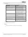
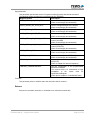
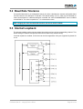
The Embedded I/O Company TDRV002-SW-25 Integrity Device Driver Multiple Channel Serial Interface Version 1.0.x User Manual Issue 1.0.0 November 2010 TEWS TECHNOLOGIES GmbH Am Bahnhof 7 25469 Halstenbek, Germany Phone: +49 (0) 4101 4058 0 Fax: +49 (0) 4101 4058 19 e-mail: [email protected] www.tews.com TDRV002-SW-25 This document contains information, which is proprietary to TEWS TECHNOLOGIES GmbH. Any reproduction without written permission is forbidden. Integrity Device Driver Multiple Channel Serial Interface TEWS TECHNOLOGIES GmbH has made any effort to ensure that this manual is accurate and complete. However TEWS TECHNOLOGIES GmbH reserves the right to change the product described in this document at any time without notice. Supported Modules: TPMC371 TPMC372 TPMC375 TPMC376 TPMC377 TPMC460 TPMC461 TPMC462 TPMC463 TPMC465 TPMC466 TPMC467 TPMC470 TCP460 TCP461 TCP462 TCP463 TCP465 TCP466 TCP467 TCP469 TCP470 TEWS TECHNOLOGIES GmbH is not liable for any damage arising out of the application or use of the device described herein. 2010 by TEWS TECHNOLOGIES GmbH Issue Description Date 1.0.0 First Issue November 23, 2010 TDRV002-SW-25 – Integrity Device Driver Page 2 of 38 Table of Contents 1 2 INTRODUCTION......................................................................................................... 4 INSTALLATION.......................................................................................................... 6 2.1 Driver Installation............................................................................................................................6 2.2 TDRV002 Applications....................................................................................................................6 3 API DOCUMENTATION ............................................................................................. 7 3.1 tdrv002Open ....................................................................................................................................7 3.2 tdrv002Close....................................................................................................................................9 3.3 tdrv002Write ..................................................................................................................................11 3.4 tdrv002Read...................................................................................................................................13 3.5 tdrv002Getc ...................................................................................................................................15 3.6 tdrv002SetBaud.............................................................................................................................17 3.7 tdrv002SetDataword .....................................................................................................................19 3.8 tdrv002SetFlowControl.................................................................................................................21 3.9 tdrv002ConfigureLoopback .........................................................................................................23 3.10tdrv002SetTrans ............................................................................................................................25 3.11tdrv002ConfigureTimeout ............................................................................................................27 4 I/O REGISTER FUNCTIONS .................................................................................... 29 4.1 WriteIODeviceRegister .................................................................................................................29 4.2 ReadIODeviceRegister .................................................................................................................31 4.3 ReadIODeviceStatus .....................................................................................................................33 5 APPENDIX................................................................................................................ 35 5.1 Software FIFOs..............................................................................................................................35 5.1.1 Changing Transmit FIFO Size ...........................................................................................35 5.1.2 Changing Receive FIFO Size ............................................................................................35 5.1.3 Changing Interrupt Event FIFO Size..................................................................................35 5.2 Baud Rate Tolerance ....................................................................................................................36 5.3 Internal Loopback .........................................................................................................................36 5.4 Example Applications...................................................................................................................37 5.4.1 tdrv002exa-readAllChans.c................................................................................................37 5.4.2 tdrv002exa-sendAllChans.c ...............................................................................................37 5.4.3 tdrv002exa-localLoopAllChans.c .......................................................................................37 5.4.4 tdrv002exa-sendRead2Chans.c ........................................................................................38 5.4.5 tdrv002exa-setTrans2Chans-RS232.c...............................................................................38 5.4.6 tdrv002exa-setTrans2Chans-RS422.c...............................................................................38 5.4.7 tdrv002exa-setTrans2Chans-RS485HD.c .........................................................................38 TDRV002-SW-25 – Integrity Device Driver Page 3 of 38 1 Introduction The TDRV002-SW-25 Integrity device driver allows the operation of TDRV002 supported boards. The driver uses a software FIFO for data that is received and for data that should be sent. Both FIFOs have a size of 2048 characters by default. An event FIFO with a size of 32 events is implemented to announce new data, and status messages. The TDRV002-SW-25 device driver supports the following features: SW-FIFO for transmit and receive configuration of the data word (data and stop bits, parity mode) setting baud rates (free scalable, no predefined values) setting I/O interface (if supported by hardware) support of hardware flow control (RTS/CTS) (if supported by hardware) support of software flow control (Xon/Xoff) support of local loopback mode observation of the link status (DCD) (if supported by hardware) The TDRV002-SW-25 supports the modules listed below: TPMC371 8 Channel Serial Interface TPMC372 4 Channel Serial Interface TPMC375 8 Channel Serial Interface (programmable Interfaces) TPMC376 4 Channel Serial Interface (programmable Interfaces) TPMC377 4 Channel Isolated Serial Interface (programmable Interfaces) TPMC460 16 Channel Serial Interface TPMC461 8 Channel Serial Interface TPMC462 4 Channel Serial Interface TPMC463 4 Channel Serial Interface TPMC465 8 Channel Serial Interface (programmable Interfaces) TPMC466 4 Channel Serial Interface (programmable Interfaces) TPMC467 4 Channel Serial Interface (programmable Interfaces) TPMC470 4 Channel Isolated Serial Interface (programmable Interfaces) TCP460 16 Channel Serial Interface TCP461 8 Channel Serial Interface TCP462 4 Channel Serial Interface TCP463 4 Channel Serial Interface TCP465 8 Channel Serial Interface (programmable Interfaces) TCP466 4 Channel Serial Interface (programmable Interfaces) TCP467 4 Channel Serial Interface (programmable Interfaces) TCP469 8 Channel Isolated Serial Interface (programmable Interfaces) TCP470 4 Channel Isolated Serial Interface (programmable Interfaces) TDRV002-SW-25 – Integrity Device Driver Page 4 of 38 In this document all supported modules and devices will be called TDRV002. Specials for certain devices will be advised. To get more information about the features and use of TDRV002 devices, it is recommended to read the manuals listed below. User manual of the used module Engineering Manual of the used module TDRV002-SW-25 – Integrity Device Driver Page 5 of 38 2 Installation The following files are located on the distribution media: Directory path ‘.\TDRV002-SW-25\’: tdrv002.c tdrv002def.h tdrv002.h tdrv002api.c tdrv002api.h examples\*.c TDRV002-SW-25-1.0.0.pdf ChangeLog.txt Release.txt TDRV002 device driver source TDRV002 driver include file TDRV002 include file for driver and application Application interface, simplifies device access Include file for API and applications Path with some small example applications PDF copy of this manual Release history Release information 2.1 Driver Installation Copy the TDRV002 driver files (tdrv002.c, tdrv002.h, and tdrv002def.h) into a desired driver or project path. The driver source file tdrv002.c must be included into the kernel project and the project must be rebuilt. The driver will be automatically started after booting the image and the driver will be requested if a matching device is detected in the system. 2.2 TDRV002 Applications Copy the TDRV002 API files (tdrv002api.c, tdrv002api.h, and tdrv002.h) into a desired application path. And include tdrv002api.c into the application project. The application source file must include tdrv002api.h. If these steps are done, the TDRV002 API can be used and the devices will be accessible. TDRV002-SW-25 – Integrity Device Driver Page 6 of 38 3 API Documentation 3.1 tdrv002Open Name tdrv002Open() – open a device Synopsis TDRV002_HANDLE *tdrv002Open ( char *name ) Description Before I/O operations can be performed to a device, a descriptor must be opened with a call to this function. This function will create and initialize a descriptor for the device. The returned handle must be specified for all other functions accessing the device. Parameters name This parameter specifies the name of the device. Generally the TDRV002 device names looks like ‘tdrv002_<major>_<minor>‘, where <major> specifies the module and <minor> specifies the local channel number. <major> and <minor> are both zero base counts. For example, the name of the third channel of the first board will be ‘tdrv002_0_2’. If more than one TDRV002 board is used, the order of the board detection and the assigned <major> number is system and BSP dependent. TDRV002-SW-25 – Integrity Device Driver Page 7 of 38 Example #include “tdrv002api.h” TDRV002_HANDLE pDev; /* ** open descriptor for a device */ pDev = tdrv002Open(“tdrv002_0_0”); if (pDev == NULL) { /* handle open error */ } Returns A device handle for the device descriptor, or NULL if the function fails. TDRV002-SW-25 – Integrity Device Driver Page 8 of 38 3.2 tdrv002Close Name tdrv002Close() – close a device Synopsis Error tdrv002Close ( TDRV002_HANDLE ) *devHdl Description This function closes a previously opened device. If this function is called, the descriptor for the device will be released and the device is no longer accessible by it. Parameters devHdl This value specifies the device handle which identifies the device. The device handle has been previously returned by tdrv002Open (see chapter 3.1 tdrv002Open). Example #include “tdrv002api.h” TDRV002_HANDLE Error pDev; errVal; /* ** close the device */ errVal = tdrv002Close(pDev); if (errVal != Success) { /* handle close error */ } TDRV002-SW-25 – Integrity Device Driver Page 9 of 38 Returns Success if device has been closed or Failure if the specified handle has been invalid. TDRV002-SW-25 – Integrity Device Driver Page 10 of 38 3.3 tdrv002Write Name tdrv002Write() – write a buffer to the device Synopsis int tdrv002Write ( TDRV002_HANDLE char int ) *devHdl, *buffer, len Description This function writes a buffer of characters to the device. The content of the specified buffer will be transferred to the device. Parameters devHdl This value specifies the device handle which identifies the device. The device handle has been previously returned by tdrv002Open (see chapter 3.1 tdrv002Open). buffer This argument specifies the start of the output buffer. len This value specifies the number of characters that shall be written. TDRV002-SW-25 – Integrity Device Driver Page 11 of 38 Example #include “tdrv002api.h” char TDRV002_HANDLE int *txtBuf = “Hello world!”; pDev; numWritten; /* ** write a string to the device */ numWritten = tdrv002Write(pDev, txtBuf, strlen(txtBuf)); if (numWritten < 0) { /* handle write error */ } else if (numWritten != strlen(txtBuf)) { /* not all characters have been written */ } else { /* write complete */ } Returns The number of transferred (written) characters, or <0 (negative “Error”) if the write function failed. TDRV002-SW-25 – Integrity Device Driver Page 12 of 38 3.4 tdrv002Read Name tdrv002Read() – read data from the device Synopsis int tdrv002Read ( TDRV002_HANDLE char int ) *devHdl, *buffer, len Description This function reads data from a device. The received characters will be transferred into the specified buffer. The function will return if the buffer is filled, no more data is available at the device, or if the timeout condition occurred. How the timeout condition can be set, is described in chapter 3.11 tdrv002ConfigureTimeout. Parameters devHdl This value specifies the device handle which identifies the device. The device handle has been previously returned by tdrv002Open (see chapter 3.1 tdrv002Open). buffer This argument specifies the start of the input buffer where the received data will be stored to. len This value specifies the size of the buffer and defines the maximum number of characters that shall be read. TDRV002-SW-25 – Integrity Device Driver Page 13 of 38 Example #include “tdrv002api.h” #define MAXTXTLEN char TDRV002_HANDLE int 25 txtBuf[MAXTXTLEN]; pDev; numRead; /* ** read data from the device */ numRead = tdrv002Read(pDev, txtBuf, MAXTXTLEN); if (numRead < 0) { /* handle read error */ } else if (numRead == 0) { /* no data read */ } else { /* read complete */ } Returns The number of transferred (read) characters, or <0 (negative “Error”) if the read function failed. TDRV002-SW-25 – Integrity Device Driver Page 14 of 38 3.5 tdrv002Getc Name tdrv002Getc() – get the next character from the device Synopsis char tdrv002Getc ( TDRV002_HANDLE ) *devHdl Description This function tries to read the next character from the specified device. If a character is available, the function will return this character immediately. If no character is available, the function will wait until a character is received and it will return this character. This function will not issue a timeout. Parameters devHdl This value specifies the device handle which identifies the device. The device handle has been previously returned by tdrv002Open (see chapter 3.1 tdrv002Open). Example #include “tdrv002api.h” char TDRV002_HANDLE inChar; pDev; /* ** get the next character from the device */ inChar = tdrv002Getc(pDev); if (inChar == EOF) { /* handle EOF error */ } TDRV002-SW-25 – Integrity Device Driver Page 15 of 38 Returns The function returns the received character, or EOF if the function has failed. TDRV002-SW-25 – Integrity Device Driver Page 16 of 38 3.6 tdrv002SetBaud Name tdrv002SetBaud() – set baud rate of the device Synopsis Error tdrv002SetBaud ( TDRV002_HANDLE UINT4 ) *devHdl, newBaud Description This function sets the baud rate for the specified device. The device will be configured to the specified baud rate or to the baud rate that matches best. (Refer to chapter 5.2 Baud Rate Tolerance) Parameters devHdl This value specifies the device handle which identifies the device. The device handle has been previously returned by tdrv002Open (see chapter 3.1 tdrv002Open). newBaud This value specifies the new baud rate. Example #include “tdrv002api.h” TDRV002_HANDLE Error pDev; errVal; /* ** set baud rate to 115200 Baud */ errVal = tdrv002SetBaud(pDev, 115200); if (errVal != Success) { /* handle error */ } TDRV002-SW-25 – Integrity Device Driver Page 17 of 38 Returns The function returns Success if baud rate has been set or Failure if the function has failed. TDRV002-SW-25 – Integrity Device Driver Page 18 of 38 3.7 tdrv002SetDataword Name tdrv002SetDataword() – set data bits, stop bit and parity mode for the device Synopsis Error tdrv002SetDataword ( TDRV002_HANDLE UINT1 SerialStopBitSetting SerialParitySetting ) *devHdl, dataBits, stopBits, parity Description This function sets the number of data bits, the length of the stop bit and the parity mode. Parameters devHdl This value specifies the device handle which identifies the device. The device handle has been previously returned by tdrv002Open (see chapter 3.1 tdrv002Open). dataBits This value specifies the new number of data bits. Allowed values are 5, 6, 7 and 8 data bits. stopBits This value specifies the length of the stop bit. The following values are allowed: Value Descrition OneStopBit The stop bit is set to a length of 1 bit. OneAndAHalfStopBits The stop bit is set to a length of 1.5 bits. (This configuration is allowed for 5 data bits only) TwoStopBits The stop bit is set to a length of 2 bit. (This configuration is allowed if 6, 7, and 8 data bits only) TDRV002-SW-25 – Integrity Device Driver Page 19 of 38 parity This value specifies the parity mode. The following values are allowed: Value Descrition NoParity No parity will be used. OddParity Odd parity will be used EvenParity Even parity will be used Example #include “tdrv002api.h” TDRV002_HANDLE Error pDev; errVal; /* ** prepare device for configuration with 8 databits, 1 stopbit ** and no parity */ errVal = tdrv002SetDataword(pDev, 8, OneStopBit, NoParity); if (errVal != Success) { /* handle error */ } Returns The function returns Success if all settings were done or Failure if at least one setting failed. TDRV002-SW-25 – Integrity Device Driver Page 20 of 38 3.8 tdrv002SetFlowControl Name tdrv002SetFlowControl() – Configure flow control for the device Synopsis Error tdrv002SetFlowControl ( TDRV002_HANDLE UINT1 ) *devHdl, newHandshake Description This function configures the flow control mode. Parameters devHdl This value specifies the device handle which identifies the device. The device handle has been previously returned by tdrv002Open (see chapter 3.1 tdrv002Open). newHandshake This value specifies the flow control (handshake) mode. The following values are allowed: Value Description TDRV002_HANDSHAKE_OFF Flow control off. TDRV002_HANDSHAKE_XON_XOFF Use Xon/Xoff flow control. TDRV002_HANDSHAKE_HARDWARE Use hardware flow control (RTS/CTS lines). TDRV002-SW-25 – Integrity Device Driver Page 21 of 38 Example #include “tdrv002api.h” TDRV002_HANDLE Error pDev; errVal; /* ** configure device using Xon/Xoff flow control */ errVal = tdrv002SetFlowControl(pDev, TDRV002_HANDSHAKE_XON_XOFF); if (errVal != Success) { /* handle error */ } Returns The function returns Success if flow control has been configured or Failure if the function failed. TDRV002-SW-25 – Integrity Device Driver Page 22 of 38 3.9 tdrv002ConfigureLoopback Name tdrv002ConfigureLoopback() – Configure local loopback mode Synopsis Error tdrv002ConfigureLoopback ( TDRV002_HANDLE *devHdl, Boolean enableLoopback ) Description This function configures if local (internal) loopback mode is enabled. This feature allows a functional test of the device without an external connection. Parameters devHdl This value specifies the device handle which identifies the device. The device handle has been previously returned by tdrv002Open (see chapter 3.1 tdrv002Open). enableLoopback This value specifies if local loopback is enabled or not. If the value is true, the internal connection will be enabled, otherwise the device will be connected to external I/O interface. Example #include “tdrv002api.h” TDRV002_HANDLE Error pDev; errVal; /* ** enable local loopback mode */ errVal = tdrv002ConfigureLoopback(pDev, true); if (errVal != Success) { /* handle error */ } TDRV002-SW-25 – Integrity Device Driver Page 23 of 38 Returns The function returns Success, or Failure if the function failed. TDRV002-SW-25 – Integrity Device Driver Page 24 of 38 3.10tdrv002SetTrans Name tdrv002SetTrans() – Configure programmable transceiver interface Synopsis Error tdrv002SetTrans ( TDRV002_HANDLE UINT4 ) *devHdl, newTrConf Description This function configures programmable transceiver interfaces. The function will fail for channels with non programmable transceivers. Parameters devHdl This value specifies the device handle which identifies the device. The device handle has been previously returned by tdrv002Open (see chapter 3.1 tdrv002Open). newTrConf This value specifies how the interface shall be configured. The value is a combination of flags, which allows individual settings. The function of the interface configuration pins can be found in the corresponding hardware User Manual. The following flags are defined: Flag Description TDRV002_TRANS_RS485_RS232_SEL RS485/RS232# configuration pin TDRV002_TRANS_HDPLX_SEL HDPLX configuration pin TDRV002_TRANS_RENA_SEL RENA configuration pin TDRV002_TRANS_RTERM_SEL RTERM configuration pin TDRV002_TRANS_TTERM_SEL TTERM configuration pin TDRV002_TRANS_SLEWLIMIT_SEL SLEWLIMIT configuration pin TDRV002_TRANS_SHDN_SEL SHDN configuration pin TDRV002_AUTO_RS485_ENABLE_SEL Enable Auto XR17D15x TDRV002-SW-25 – Integrity Device Driver RS485 Operation mode of Page 25 of 38 For a simpler configuration, the definitions of common configurations can be used. These definitions can be used instead of the combination of flags above. The following configurations are defined: Configuration Description TDRV002_INTF_OFF Interface disabled TDRV002_INTF_RS232 RS232 TDRV002_INTF_RS422 RS422 (Multidrop / Full duplex) TDRV002_INTF_RS485FDM RS485 (Full duplex master) TDRV002_INTF_RS485FDS RS485 (Full duplex slave) TDRV002_INTF_RS485HD RS485 (Half duplex) Example #include “tdrv002api.h” TDRV002_HANDLE Error pDev; errVal; /* ** 1st: configure RS422 */ errVal = tdrv002SetTrans(pDev, TDRV002_INTF_RS422); if (errVal != Success) { /* handle error */ } … /* ** 2nd: configure RS422 (using flags) */ errVal = tdrv002SetTrans(pDev, ( TDRV002_TRANS_RS485_RS232_SEL | TDRV002_TRANS_RTERM_SEL)); if (errVal != Success) { /* handle error */ } Returns The function returns Success if the interface has been configured or Failure if the function failed. TDRV002-SW-25 – Integrity Device Driver Page 26 of 38 3.11tdrv002ConfigureTimeout Name tdrv002ConfigureTimeout() – Configure timeouts Synopsis Error tdrv002ConfigureTimeout ( TDRV002_HANDLE Boolean Boolean int ) *devHdl, immReturn, neverTimeout, newTimeout Description This function defines the timeout behavior of tdrv002Read (see chapter 3.4 tdrv002Read). Parameters devHdl This value specifies the device handle which identifies the device. The device handle has been previously returned by tdrv002Open (see chapter 3.1 tdrv002Open). immReturn If this value is true, the read operation will return immediately, even if no data is available. The following arguments will be ignored. neverTimeout If this value is true, the read operation will wait until at least one character is received. The specified timeout time will be ignored. (This value will be ignored if immReturn is true.) newTimeout This value specifies the time the read function is willing to wait for a character receive before it returns. The timeout is specified in seconds. (This value will be ignored if immReturn or neverTimeout is true.) TDRV002-SW-25 – Integrity Device Driver Page 27 of 38 Example #include “tdrv002api.h” TDRV002_HANDLE Error pDev; errVal; /* ** Set timeout to 10 seconds */ errVal = tdrv002ConfigureTimeout(pDev, false, false, 10) if (errVal != Success) { /* handle error */ } … /* ** Set timeout for immediate read */ errVal = tdrv002ConfigureTimeout(pDev, true, false, 0) if (errVal != Success) { /* handle error */ } Returns The function returns Success, or Failure if an invalid device is specified. TDRV002-SW-25 – Integrity Device Driver Page 28 of 38 4 I/O Register Functions These functions are used by the TDRV002 API to access the TDRV002. Therefore, the following chapter just gives a short overview over the available accesses. Most accesses are described in the Integrity BSP Guide in the chapter ‘Serial Interfaces’. The TDRV002 specific functions will be described below more detailed. 4.1 WriteIODeviceRegister Name WriteIODeviceRegister() – Write to device I/O register Synopsis Error WriteIODeviceRegister ( IODevice TheIODevice, Value RegisterNumber, Value RegisterValue ) Description This function writes to the specified devices I/O register. Parameters IODevice This parameter specifies the IODevice. TDRV002-SW-25 – Integrity Device Driver Page 29 of 38 RegisterNumber This parameter specifies the device I/O register number (function) that shall be accessed. The following register numbers are implemented for the TDRV002: Register Number Description IODEV_SERIAL_NO_DATA_BITS Configure the number of transferred data bits (Refer to the Integrity documentation) IODEV_SERIAL_NO_STOP_BITS Configure the length of the stop bit (Refer to the Integrity documentation) IODEV_SERIAL_PARITY Configure the parity mode (Refer to the Integrity documentation) IODEV_SERIAL_BAUDRATE Configure the baud rate (Refer to the Integrity documentation) The baud rate may be modified to the nearest matching value. For more information refer to chapter 5.2 Baud Rate Tolerance. IODEV_SERIAL_SW_FLOW_CONTROL Enable/Disable software flow control (Xon/Xoff) (Refer to the Integrity documentation) IODEV_SERIAL_HW_FLOW_CONTROL Enable/Disable hardware flow (RTS/CTS) (Refer to the Integrity documentation) IODEV_SERIAL_DATA Send a character (Refer to the Integrity documentation) TDRV002_LOCALLOOP_MODE Enable/Disable local (internal) loopback mode (Refer to chapter 5.3 Internal Loopback) TDRV002_TRANSINTERFACE Configure programmable transceiver interface RegisterValue specifies the new configuration value (Refer to chapter 3.10 tdrv002SetTrans) control RegisterValue This parameter specifies the registers value. Returns Success on successful execution, or a suitable error code if the function fails. TDRV002-SW-25 – Integrity Device Driver Page 30 of 38 4.2 ReadIODeviceRegister Name ReadIODeviceRegister() – Read device I/O register Synopsis Error ReadIODeviceRegister ( IODevice TheIODevice, Value RegisterNumber, Value *TheValue ) Description This function reads the value from a specified devices I/O register. Parameters TheIODevice This parameter specifies the IODevice. TDRV002-SW-25 – Integrity Device Driver Page 31 of 38 RegisterNumber This parameter specifies the device I/O register number (function) that shall be accessed. The following register numbers are implemented for the TDRV002: Register Number Description IODEV_SERIAL_NO_DATA_BITS Get number of configured data bits (Refer to the Integrity documentation) IODEV_SERIAL_NO_STOP_BITS Get the configured length of the stop bit (Refer to the Integrity documentation) IODEV_SERIAL_PARITY Get the configured parity mode (Refer to the Integrity documentation) IODEV_SERIAL_BAUDRATE Get the actual configured baud rate (Refer to the Integrity documentation) IODEV_SERIAL_SW_FLOW_CONTROL Get the configuration of the software flow control (Xon/Xoff) (Refer to the Integrity documentation) IODEV_SERIAL_HW_FLOW_CONTROL Get the configuration of the hardware flow control (RTS/CTS) (Refer to the Integrity documentation) IODEV_SERIAL_DATA Read a received character (Refer to the Integrity documentation) IODEV_LINK_STATUS Get the link state (state of DCD line) (Refer to the Integrity documentation) TDRV002_LOCALLOOP_MODE Get configuration of the local loopback mode (RTS/CTS) (Refer to chapter 5.3 Internal Loopback) TDRV002_TRANSINTERFACE Get the configuration of the programmable transceiver interface. The returned value is a combination of flags compatible to the values used for WriteIODeviceRegister. (Refer also to chapter 3.10 tdrv002SetTrans) TheValue This parameter points to a buffer where the read value will be returned. Returns Success on successful execution, or a suitable error code if the function fails. TDRV002-SW-25 – Integrity Device Driver Page 32 of 38 4.3 ReadIODeviceStatus Name ReadIODeviceStatus() – Read device I/O status Synopsis Error ReadIODeviceRegister ( IODevice TheIODevice, Value StatusNumber, DestAddress Destination, Address Length ) Description This function reads the value from a specified devices I/O register. Parameters TheIODevice This parameter specifies the IODevice. StatusNumber This parameter specifies the status number that shall be read. The following status numbers are implemented for the TDRV002: Status Number Description IODEV_INTR_STATUS Get stored interrupt status (refer to Integrity manual) TDRV002_STAT_RX Get receive status Destination This parameter points to a application supplied buffer where the status information will be returned. Status Number Status structure IODEV_INTR_STATUS InterruptStatus – Supported Interrupt Status: LinkDetected, LinkLost, ReadCharacterCompleted, NoPendingInterrupt (For a description refer to the Integrity manuals) TDRV002_STAT_RX tdrv002RxStat (see Special Status Structures below) Length This parameter specifies the length of the supplied buffer. TDRV002-SW-25 – Integrity Device Driver Page 33 of 38 Special Status Structures typedef struct { Value Boolean Boolean Boolean Boolean } tdrv002RxStat; numAvail; fifoOverrunErr; overrunErr; parityErr; framingErr; numAvail Returns the number of available characters in the SW-FIFO. fifoOverrunErr Returns true if a FIFO overrun error has occurred. The driver will remove the error flag internally. overrunErr Returns true if an overrun error, indicated by hardware, has occurred. The driver will remove the error flag internally. parityErr Returns true if a parity error has occurred. The driver will remove the error flag internally. framingErr Returns true if a framing error has occurred. The driver will remove the error flag internally. Returns Success on successful execution, or a suitable error code if the function fails. TDRV002-SW-25 – Integrity Device Driver Page 34 of 38 5 Appendix 5.1 Software FIFOs There are three FIFOs used for this driver. First, there is a transmit FIFO, where data is stored before it is written to the UART channel. This allows writing data to the device also if the previous characters have not been transferred. The application can continue working and the data will be written asynchronously. Second, there is a receive FIFO. All incoming characters will be stored into this FIFO and the read function will transfer data from this FIFO to the application. This FIFO prevents data loss. Received data will be stored into the FIFO and can be read by the application later. The third and last FIFO stores events that occur for the serial channel. The events will be stored into the FIFO. If the FIFO is filled and a new event shall be stored, the oldest event will be overwritten. If a new event is stored, the driver will notify a waiting task (using INTERRUPT_IODeviceNotifyTask()). 5.1.1 Changing Transmit FIFO Size The size of the transmit FIFO is specified in tdrv002def.h. To change the number of characters that can be stored in the FIFO, change the value of the TXBUFSIZE definition. After changing the FIFO size, the driver must be rebuilt. 5.1.2 Changing Receive FIFO Size The size of the receive FIFO is specified in tdrv002def.h. To change the number of characters that can be stored in the FIFO, change the value of the RXBUFSIZE definition. After changing the FIFO size, the driver must be rebuilt. 5.1.3 Changing Interrupt Event FIFO Size The size of the Interrupt Event FIFO is specified in tdrv002def.h. To change the number of characters that can be stored in the FIFO, change the value of the TDRV002_NUM_SERIAL_STATUS definition. After changing the FIFO size, the driver must be rebuilt. TDRV002-SW-25 – Integrity Device Driver Page 35 of 38 5.2 Baud Rate Tolerance If a specified baud rate is not configurable exactly, the driver calculates the nearest configurable baud rate and checks if the difference is tolerable. The default setting is 2.5%, which will be tolerated for most communications. If a different tolerance is needed, the value of MAXBAUDDIFF can be modified 1 in tdrv002def.h. The value is specified in /10% of the desired value. After changing the value for baud rate tolerance, the driver must be rebuilt. 5.3 Internal Loopback The internal loopback mode connects output lines with input lines of the corresponding channel. This allows testing the software and general board access without any external wiring. If internal loopback is enabled, all I/O lines can be used regardless if they are supported by board I/O or not. TDRV002-SW-25 – Integrity Device Driver Page 36 of 38 5.4 Example Applications The example application shall give an overview about the use of the TDRV002 devices and the how to use the TDRV002 API. 5.4.1 tdrv002exa-readAllChans.c This simple example executes one simple read data on every TDRV002 device and prints the received data. Program flow: open devices set receive timeout read input data and print out close devices 5.4.2 tdrv002exa-sendAllChans.c This simple example sends a small text on every TDRV002 device. Program flow: open devices send text to devices close devices 5.4.3 tdrv002exa-localLoopAllChans.c This is a simple example which sends data in local loopback mode and receives and prints out the data afterwards. Program flow: open devices set receive timeout enable local loop back mode send text to devices read input data and print out disable local loop back mode close devices TDRV002-SW-25 – Integrity Device Driver Page 37 of 38 5.4.4 tdrv002exa-sendRead2Chans.c This example transfers a text from one TDRV002 device to a second TDRV002 device and back. If the text has been transferred a few times, the baud rate will be changed and the text will be transferred again. This will be repeated for the configured baud rates. Program flow: open devices copy source text into buffer 1 loop over baud rates configure baud rate configure receive timeout repeat for n-times st send text (buffer 1) to 1 device nd receive text (in buffer 2) from 2 device nd send text (buffer 2) to 2 device receive text (in buffer 1) from 1st device compare source text and buffer 1 close devices By default, this example uses ‘tdrv002_0_1’ and ‘tdrv002_0_2’. 5.4.5 tdrv002exa-setTrans2Chans-RS232.c This example configures two channels with programmable transceiver into RS232 mode. Program flow: open devices configure programmable interfaces for RS232 close devices By default, this example uses ‘tdrv002_0_1’ and ‘tdrv002_0_2’. 5.4.6 tdrv002exa-setTrans2Chans-RS422.c This example configures two channels with programmable transceiver into RS422 mode. Program flow: open devices configure programmable interfaces for RS422 close devices By default, this example uses ‘tdrv002_0_1’ and ‘tdrv002_0_2’. 5.4.7 tdrv002exa-setTrans2Chans-RS485HD.c This example configures two channels with programmable transceiver into RS485 mode. Program flow: open devices configure programmable interfaces for RS485HD close devices By default, this example uses ‘tdrv002_0_1’ and ‘tdrv002_0_2’. TDRV002-SW-25 – Integrity Device Driver Page 38 of 38