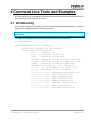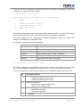
1
The Embedded I/O Company TDRV002-SW-72 LynxOS Device Driver Multiple Channel Serial Interface Version 1.3.x User Manual Issue 1.3.1 September 2012 TEWS TECHNOLOGIES GmbH Am Bahnhof 7 25469 Halstenbek, Germany Phone: +49 (0) 4101 4058 0 Fax: +49 (0) 4101 4058 19 e-mail: [email protected] www.tews.com TDRV002-SW-72 This document contains information, which is proprietary to TEWS TECHNOLOGIES GmbH. Any reproduction without written permission is forbidden. LynxOS Device Driver Multiple Channel Serial Interface TEWS TECHNOLOGIES GmbH has made any effort to ensure that this manual is accurate and complete. However TEWS TECHNOLOGIES GmbH reserves the right to change the product described in this document at any time without notice. Supported Modules: TPMC371 TPMC372 TPMC375 TPMC376 TPMC377 TPMC460 TPMC461 TPMC462 TPMC463 TPMC465 TPMC466 TPMC467 TPMC470 TCP460 TCP461 TCP462 TCP463 TCP465 TCP466 TCP467 TCP469 TCP470 TEWS TECHNOLOGIES GmbH is not liable for any damage arising out of the application or use of the device described herein. 2005-2012 by TEWS TECHNOLOGIES GmbH Issue Description Date 1.0.0 First Issue March 24, 2005 1.0.1 New Address TEWS LLC, New File List March 1, 2007 1.1.0 Additional Modules supported , Programmable Transceiver Support, command line tool tdrv002config added January 16, 2009 1.2.0 Address TEWS LLC removed, description for LynxOS 5.x December 9, 2009 1.3.0 Support of new boards April 29, 2011 1.3.1 Chapter “Known Problems” added September 13, 2012 TDRV002-SW-72 – LynxOS Device Driver Page 2 of 25 Table of Contents 1 2 INTRODUCTION......................................................................................................... 4 INSTALLATION.......................................................................................................... 6 2.1 Device Driver Installation ...............................................................................................................7 2.1.1 Static Installation ..................................................................................................................7 2.1.1.1 Build the Driver Object..................................................................................................7 2.1.1.2 Create Device Information Declaration ........................................................................7 2.1.1.3 Modify the Device and Driver Configuration File ..........................................................7 2.1.1.4 Rebuild the Kernel ........................................................................................................8 2.1.2 Dynamic Installation .............................................................................................................9 2.1.2.1 Build the Driver Object..................................................................................................9 2.1.2.2 Create Device Information Declaration ........................................................................9 2.1.2.3 Uninstall dynamic loaded Driver ...................................................................................9 2.1.3 Device Information Definition File ......................................................................................10 2.1.4 Configuration File: CONFIG.TBL .......................................................................................12 3 TDRV002 DEVICE DRIVER PROGRAMMING......................................................... 13 3.1.1 3.1.2 3.1.3 3.1.4 3.1.5 3.1.6 4 TIOSHWH ..........................................................................................................................14 TIOCHWH ..........................................................................................................................15 TIOSLOCLOOP .................................................................................................................16 TIOCLOCLOOP .................................................................................................................17 TIOSELFTEST ...................................................................................................................18 TIOSETINTERFACE..........................................................................................................20 COMMAND LINE TOOLS AND EXAMPLES ........................................................... 22 4.1 tdrv002config.................................................................................................................................22 4.2 tdrv002exa .....................................................................................................................................24 5 APPENDIX................................................................................................................ 25 5.1 Known Problems...........................................................................................................................25 5.1.1 Data Loss with Hardware Handshake................................................................................25 5.1.2 Inconsistent Definitions for Baud Rates .............................................................................25 TDRV002-SW-72 – LynxOS Device Driver Page 3 of 25 1 Introduction The TDRV002-SW-72 LynxOS device driver is a full-duplex tty device driver which allows the operation of a TDRV002 product family with DRM based PCI interface. The TDRV002-SW-72 device driver is based on the standard LynxOS terminal manager. Due to this way of implementation the driver interface and function is absolute compatible to the standard LynxOS terminal driver. All standard utility programs for configuration and maintaining terminal interfaces could be used in the same manner. There is only one exception; the TDRV002-SW-72 can’t be used as console driver. Additional supported features: Extended baud rates up to 5.5 MBaud. Each channel has a 64 Byte transmit and receive FIFO with programmable trigger levels Hardware (RTS/CTS) and software handshake (Xon/Xoff) direct controlled by the serial controller. The advantage of this feature is that the transmission of characters will immediately stop as soon as a complete character is transmitted and not when the transmit FIFO is empty for handshake under software control. Control of Full Modem Lines Direct support of different physical interfaces Configuration of programmable transceiver. En-/disable of local loop back mode. Selftest function to check hardware. Receive hardware handshake is not fully implemented in terminal manager interface. Control of modem- and handshake-lines is not fully supported by older LynxOS versions. Support is implemented and tested with LynxOS 5.0.0 and Patch-070. The TDRV002-SW-72 device driver supports the modules listed below: TPMC371 8 Channel Serial Interface (Conduction Cooled PMC) TPMC372 4 Channel Serial Interface (Conduction Cooled PMC) TPMC375 8 Channel Serial Interface (prog. Transceiver) (Conduction Cooled PMC) TPMC376 4 Channel Serial Interface (prog. Transceiver) (Conduction Cooled PMC) TPMC377 4 Chan. Isolated Serial Interface (prog. Transcv.) (Conduction Cooled PMC) TPMC460 2 x 8 Channel Serial Interface (PMC) TPMC461 8 Channel Serial Interface (PMC) TPMC462 4 Channel Serial Interface (PMC) TPMC463 4 Channel Serial Interface (PMC) TPMC465 8 Channel Serial Interface (prog. Transceiver) (PMC) TPMC466 4 Channel Serial Interface (prog. Transceiver) (PMC) TPMC467 4 Channel Serial Interface (prog. Transceiver) (PMC) TPMC470 4 Chan. Isolated Serial Interface (prog. Transcv.) (PMC) … continued … TDRV002-SW-72 – LynxOS Device Driver Page 4 of 25 … continued … TCP460 2 x 8 Channel Serial Interface (compactPCI) TCP461 8 Channel Serial Interface (compactPCI) TCP462 4 Channel Serial Interface (compactPCI) TCP463 4 Channel Serial Interface (compactPCI) TCP465 8 Channel Serial Interface (prog. Transceiver) (compactPCI) TCP466 4 Channel Serial Interface (prog. Transceiver) (compactPCI) TCP467 4 Channel Serial Interface (prog. Transceiver) (compactPCI) TCP469 4 Chan. Isolated Serial Interface (prog. Transcv.) (compactPCI) TCP470 4 Chan. Isolated Serial Interface (prog. Transcv.) (compactPCI) In this document all supported modules and devices will be called TDRV002. Specials for certain devices will be advised. To get more information about the features and use of TDRV002 devices it is recommended to read the manuals listed below. User manual of the TDRV002 device Engineering Manual of the TDRV002 device TDRV002-SW-72 – LynxOS Device Driver Page 5 of 25 2 Installation Following files are located on the distribution media: Directory path TDRV002-SW-72: TDRV002-SW-72-SRC.tar.gz TDRV002-SW-72-1.3.1.pdf ChangeLog.txt Release.txt GZIP compressed archive with driver source code PDF copy of this manual Release history Release information For installation the files have to be copied to the desired target directory. The GZIP compressed archive TDRV002-SW-72-SRC.tar.gz contains the following files and directories: Directory path ‘tdrv002’: tdrv002.c tdrv002.h tdrv002_info.c tdrv002_info.h tdrv002.cfg tdrv002.import Makefile example/tdrv002exa.c example/tdrv002config.c example/Makefile Driver source code Definitions and data structures for driver and application Device information definition Device information definition header Driver configuration file include Linker import file Device driver make file Example application source Application source to configure programmable transceivers Example application source In order to perform an installation, extract all files of the archive TDRV002-SW-72-SRC.tar.gz to the desired target directory and copy the files into the system tree as described below. (1) Extract driver files: tar -xzvf TDRV002-SW-72-SRC.tar.gz tdrv002/ (2) Create a new directory in the system drivers directory path /sys/drivers.xxx, where xxx represents the BSP that supports the target hardware. For example: /sys/drivers.pp_drm/tdrv002 or /sys/drivers.cpci_x86/tdrv002 (3) Copy the following files to this directory: tdrv002.c, tdrv002.import, Makefile (4) Copy tdrv002.h to /usr/include/ (5) Copy tdrv002_info.c to /sys/devices.xxx/ or /sys/devices if /sys/devices.xxx does not exist (xxx represents the BSP). (6) Copy tdrv002_info.h to /sys/dheaders/ (7) Copy tdrv002.cfg to /sys/cfg.xxx/, where xxx represents the BSP for the target platform. For example: /sys/cfg.ppc or /sys/cfg.x86 ... TDRV002-SW-72 – LynxOS Device Driver Page 6 of 25 2.1 Device Driver Installation The two methods of driver installation are as follows: (1) Static Installation (2) Dynamic Installation (only native LynxOS 4 systems) 2.1.1 Static Installation With this method, the driver object code is linked with the kernel routines and is installed during system start-up. 2.1.1.1 Build the Driver Object (1) Change to the directory /sys/drivers.xxx/tdrv002, where xxx represents the BSP that supports the target hardware. (2) To update the library /sys/lib/libdrivers.a enter: make install 2.1.1.2 Create Device Information Declaration (1) Change to the directory /sys/devices.xxx/ or /sys/devices if /sys/devices.xxx does not exist (xxx represents the BSP). (2) Add the following dependencies to the Makefile DEVICE_FILES_all = ... tdrv002_info.x And at the end of the Makefile tdrv002_info.o:$(DHEADERS)/tdrv002_info.h (3) To update the library /sys/lib/libdevices.a enter: make install 2.1.1.3 Modify the Device and Driver Configuration File In order to insert the driver object code into the kernel image, an appropriate entry in file CONFIG.TBL must be created. (1) Change to the directory /sys/lynx.os/ respective /sys/bsp.xxx, where xxx represents the BSP that supports the target hardware. (2) Create an entry at the end of the file CONFIG.TBL Insert the following entry at the end of this file. I:tdrv002.cfg TDRV002-SW-72 – LynxOS Device Driver Page 7 of 25 2.1.1.4 Rebuild the Kernel (1) Change to the directory /sys/lynx.os/ (/sys/bsp.xxx) (2) Enter the following command to rebuild the kernel: make install (3) Reboot the newly created operating system by the following command (not necessary for KDIs): reboot –aN The N flag instructs init to run mknod and create all the nodes mentioned in the new nodetab. (4) After reboot you should find the following new devices (depends on the device configuration): /dev/tdrv002a1, /dev/tdrv002a2, /dev/tdrv002a3, … /dev/tdrv002b1, /dev/tdrv002b2, … TDRV002-SW-72 – LynxOS Device Driver Page 8 of 25 2.1.2 Dynamic Installation This method allows you to install the driver after the operating system is booted. The driver object code is attached to the end of the kernel image and the operating system dynamically adds this driver to its internal structures. The driver can also be removed dynamically. 2.1.2.1 Build the Driver Object (1) Change to the directory /sys/drivers.xxx/tdrv002, where xxx represents the BSP that supports the target hardware. (2) To make the dynamic link-able driver enter: make dldd 2.1.2.2 Create Device Information Declaration (1) Change to the directory /sys/drivers.xxx/tdrv002, where xxx represents the BSP that supports the target hardware. (2) To create a device definition file for the major device (this works only on native system) make t002info (3) To install the driver enter: drinstall –c tdrv002.obj If successful, drinstall returns a unique <driver-ID> (4) To install the major device enter: devinstall –c –d <driver-ID> t002info The <driver-ID> is returned by the drinstall command (5) To create nodes for the devices enter: mknod /dev/tdrv002a1 c <major_no> 0 mknod /dev/tdrv002a2 c <major_no> 1 mknod /dev/tdrv002a3 c <major_no> 2 … The <major_no> is returned by the devinstall command. If all steps are successful completed the TDRV002 is ready to use. 2.1.2.3 Uninstall dynamic loaded Driver To uninstall the TDRV002 device enter the following commands: devinstall –u –c <device-ID> drinstall –u <driver-ID> TDRV002-SW-72 – LynxOS Device Driver Page 9 of 25 2.1.3 Device Information Definition File The device information definition contains information necessary to install the TDRV002 major device. The implementation of the device information definition is done through a C structure, which is defined in the header file tdrv002_info.h. This structure contains the following parameter: PCIBusNumber Contains the PCI bus number at which the TDRV002 compatible device is connected. Valid bus numbers are in range from 0 to 255. PCIDeviceNumber Contains the device number (slot) at which the TDRV002 compatible device is connected. Valid device numbers are in range from 0 to 31. If both PCIBusNumber and PCIDeviceNumber are –1 then the driver will auto scan for the TDRV002 compatible device. The first device found in the scan order will be allocated by the driver for this major device. Already allocated devices can’t be allocated twice. This is important to know if there are more than one TDRV002 major devices. FIFO_Settings[] Contains the trigger level for receive and transmit FIFO. And the transceiver startup configuration for programmable transceivers. Valid settings for receive and transmit FIFO are between 1 and 64. Valid transceiver configurations are defined in tdrv002.h. sg This structure contains initial tty parameter like baud rate special characters and so on. Refer also to the tty man pages. A device information definition is unique for every TDRV002 major device. The file tdrv002_info.c on the distribution disk contains two device information declarations, tdrv002A for the first major device and tdrv002B for the second major device. Some modules of the TDRV002 series (supporting more than 8 channels) are using more than one PCI Devices, for these modules a major device for each of the controllers have to be installed. If the driver should support more than two major devices it is necessary to copy and paste an existing declaration and rename it with a unique name, for example tdrv002C, tdrv002D and so on. It is also necessary to modify the device and driver configuration file, respectively the configuration include file tdrv002.cfg. TDRV002-SW-72 – LynxOS Device Driver Page 10 of 25 The following device declaration information uses the auto find method to detect a TDRV002 compatible device on the PCI bus. The Rx trigger level is set to 30 Byte and the Tx trigger level is set to 8 for all minor devices. TDRV002_INFO tdrv002A = { -1, -1, { /* auto find the TDRV002 on any PCI bus /* Rx, Tx trigger level */ { 30, 8, TDRV002_INTF_OFF }, /* { 30, 8, TDRV002_INTF_OFF }, /* { 30, 8, TDRV002_INTF_OFF }, /* { 30, 8, TDRV002_INTF_OFF }, /* { 30, 8, TDRV002_INTF_OFF }, /* { 30, 8, TDRV002_INTF_OFF }, /* { 30, 8, TDRV002_INTF_OFF }, /* { 30, 8, TDRV002_INTF_OFF }, /* channel channel channel channel channel channel channel channel 0 1 2 3 4 5 6 7 ( ( ( ( ( ( ( ( */ minor minor minor minor minor minor minor minor device device device device device device device device 0 1 2 3 4 5 6 7 ) ) ) ) ) ) ) ) */ */ */ */ */ */ */ */ }, { B9600, B9600, /* input and output speed */ 'H' - '@', /* erase char */ -1, /* 2nd erase char */ 'U' - '@', /* kill char */ ECHO | CRMOD, /* mode */ 'C' - '@', /* interrupt character */ '\\' - '@', /* quit char */ 'Q' - '@', /* start char */ 'S' - '@', /* stop char */ 'D' - '@', /* EOF */ -1, /* brk */ (LCRTBS | LCRTERA | LCRTKIL | LCTLECH), /* local mode word 'Z' - '@', /* process stop */ 'Y' - '@', /* delayed stop */ 'R' - '@', /* reprint line */ 'O' - '@', /* flush output */ 'W' - '@', /* word erase */ 'V' - '@' /* literal next char */ */ } }; TDRV002-SW-72 – LynxOS Device Driver Page 11 of 25 2.1.4 Configuration File: CONFIG.TBL The device and driver configuration file CONFIG.TBL (respective config.tbl on LynxOS 5.0 systems) contains entries for device drivers and its major and minor device declarations. Each time the system is rebuild, the config utility read this file and produces a new set of driver and device configuration tables and a corresponding nodetab. To install the TDRV002 driver and devices into the LynxOS system, the configuration include file tdrv002.cfg must be included in the CONFIG.TBL. The file tdrv002.cfg on the distribution media contains the driver entry (C:tdrv002:\...) and a major device entry (D:TDRV002 1-8:tdrv002A::) with one minor device entry (“N: tdrv002ax”) for each channel, where x represents the zero-based channel number. If the driver should support more than one major device, the following entries for major and minor devices must be enabled by removing the comment character (#). By copy and paste an existing major and minor entries and renaming the new entries, it is possible to add any number of additional TDRV002 devices. This example shows a driver entry with one major device and eight minor devices: # # # # Format: C:driver-name:open:close:read:write:select:control:install:uninstall D:device-name:info-block-name:raw-partner-name N:node-name:minor-dev C:tdrv002:\ :td002open:td002close:td002read:td002write:\ ::td002ioctl:td002install:td002uninstall D:TDRV002 1:tdrv002A:: N:tdrv002a1:0 N:tdrv002a2:1 N:tdrv002a3:2 N:tdrv002a4:3 N:tdrv002a5:4 N:tdrv002a6:5 N:tdrv002a7:6 N:tdrv002a8:7 The configuration above creates the following nodes in the /dev directory. /dev/tdrv002a1 /dev/tdrv002a2 /dev/tdrv002a3 /dev/tdrv002a4 /dev/tdrv002a5 /dev/tdrv002a6 /dev/tdrv002a7 /dev/tdrv002a8 TDRV002-SW-72 – LynxOS Device Driver Page 12 of 25 3 TDRV002 Device Driver Programming The TDRV002-SW-72 device driver is based on the standard LynxOS terminal manager. Due to this way of implementation the driver interface and function is absolute compatible to the standard LynxOS terminal driver. The TDRV002-SW-72 device driver supports some additional ioctl functions to use some extra features. The table below shows the additional functions (defined in tdrv002.h): Command Code Description TIOSHWH 290 enable hardware handshake (RTS/CTS) (only available if channel supports RTS/CTS) TIOCHWH 291 disable hardware handshake (RTS/CTS) (only available if channel supports RTS/CTS) TIOSLOCLOOP 292 enable local loopback mode TIOCLOCLOOP 293 disable local loopback mode TIOSELFTEST 294 execute selftest TIOSETINTERFACE 295 change configuration of programmable tranceiver TDRV002-SW-72 – LynxOS Device Driver Page 13 of 25 3.1.1 TIOSHWH NAME TIOSHWH – Enable hardware handshake DESCRIPTION This function enables the hardware handshake mode of the TDRV002 device. This function is only available if the hardware channel supports RTS/CTS lines. There is no argument for this function. This function enabled hardware handshake, but it does not prevent of data loss by FIFO overrun. EXAMPLE #include <tdrv002.h> int result; result = ioctl( fd, TIOSHWH, NULL); if (result < 0) { /* handle ioctl error */ } ERROR CODES Error Code Description EBUSY The device is busy (for example the self test active). EPERM The hardware does not support RTS/CTS. All other returned error codes are system error conditions. TDRV002-SW-72 – LynxOS Device Driver Page 14 of 25 3.1.2 TIOCHWH NAME TIOCHWH – Disable hardware handshake DESCRIPTION This function disables the hardware handshake mode of the TDRV002 device. This function is only available if the hardware channel supports RTS/CTS lines. There is no argument for this function. EXAMPLE #include <tdrv002.h> int result; result = ioctl( fd, TIOCHWH, NULL); if (result < 0) { /* handle ioctl error */ } ERROR CODES Error Code Description EBUSY The device is busy (for example the self test is active). All other returned error codes are system error conditions. TDRV002-SW-72 – LynxOS Device Driver Page 15 of 25 3.1.3 TIOSLOCLOOP NAME TIOSLOCLOOP – Enables local hardware loop back mode DESCRIPTION This function enables the local hardware loop back mode of the TDRV002 device. There is no argument for this function. EXAMPLE #include <tdrv002.h> int result; result = ioctl( fd, TIOSLOCLOOP, NULL); if (result < 0) { /* handle ioctl error */ } ERROR CODES Error Code Description EBUSY The device is busy (for example the self test is active). All other returned error codes are system error conditions. TDRV002-SW-72 – LynxOS Device Driver Page 16 of 25 3.1.4 TIOCLOCLOOP NAME TIOCLOCLOOP – Disables local hardware loop back mode DESCRIPTION This function disables the local hardware loop back mode of the TDRV002 device. There is no argument for this function. EXAMPLE #include <tdrv002.h> int result; result = ioctl( fd, TIOCLOCLOOP, NULL); if (result < 0) { /* handle ioctl error */ } ERROR CODES Error Code Description EBUSY The device is busy (for example the self test is active). All other returned error codes are system error conditions. TDRV002-SW-72 – LynxOS Device Driver Page 17 of 25 3.1.5 TIOSELFTEST NAME TIOSELFTEST – Performs a local selftest on the device DESCRIPTION This function performs a local selftest on the device. A buffer of data (1kB) will be sent in local loop back mode. The size of transferred data will be checked, received characters will be compared with the transmitted characters. The transmission will use the standard interrupt functions. For RTS, CTS, DTR, DSR, RI, DCD this function will check both states. The function returns an unsigned long value as argument (arg) containing a detailed result of the selftest. The result is an ored value of the following flags (defined in tdrv002.h): Flag State TDRV002_STS_TRM_TIMEOUT The transmission timed out, one ore more characters have not been sent. TDRV002_STS_RCV_TIMEOUT The reception timed out, not all characters have been received. TDRV002_STS_RCV_OVERFLOW The device has received too many characters. TDRV002_STS_DATA_CORRUPTED The sent and received characters are different. TDRV002_STS_RTSCTS_NOFUNC RTS/CTS function is damaged TDRV002_STS_DTRDSR_NOFUNC DTR/DSR function is damaged TDRV002_STS_RI_NOFUNC RI function is damaged TDRV002_STS_DCD_NOFUNC DCD function is damaged If no flag is set, all tests have been completed successfully. EXAMPLE #include <tdrv002.h> int unsigned long result; selftestResult; result = ioctl( fd, TIOSELFTEST, &selftestResult); if (result < 0) { /* handle ioctl error */ } TDRV002-SW-72 – LynxOS Device Driver Page 18 of 25 ERROR CODES Error Code Description EBUSY The device is busy (for example the selftest is active). ENOMEM The function cannot allocate memory for Rx/Tx test. All other returned error codes are system error conditions. TDRV002-SW-72 – LynxOS Device Driver Page 19 of 25 3.1.6 TIOSETINTERFACE NAME TIOSETINTERFACE – Changes configuration of programmable transceiver DESCRIPTION This I/O control function sets a new I/O interface configuration. This function is only usable for devices supporting a programmable I/O interface (programmable transceivers). The function specific control parameter arg specifies the new configuration of the programmable transceivers. (Only allowed for channels supporting a programmable I/O interface) A combination of the flags below must be specified to configure the interface. (Defined in tdrv002.h): Flag Description TDRV002_TRANS_RS485_RS232_SEL RS485/RS232# configuration pin TDRV002_TRANS_HDPLX_SEL HDPLX configuration pin TDRV002_TRANS_RENA_SEL RENA configuration pin TDRV002_TRANS_RTERM_SEL RTERM configuration pin TDRV002_TRANS_TTERM_SEL TTERM configuration pin TDRV002_TRANS_SLEWLIMIT_SEL SLEWLIMIT configuration pin TDRV002_TRANS_SHDN_SEL SHDN configuration pin TDRV002_AUTO_RS485_SEL_ENABLE enable Auto XR17D15x RS485 Operation mode of The function of the interface configuration pins can be found in the hardware User Manual. There are predefined values of the interface configuration described in the hardware manual, you can just OR the predefined value instead of a list of configuration flags. Below is a list of the values: Macro value Description TDRV002_INTF_OFF interface disabled TDRV002_INTF_RS232 RS232 TDRV002_INTF_RS422 RS422 (Multidrop / Full duplex) TDRV002_INTF_RS485FDM RS485 (Full duplex master) TDRV002_INTF_RS485FDS RS485 (Full duplex slave) TDRV002_INTF_RS485HD RS485 (Half duplex) TDRV002-SW-72 – LynxOS Device Driver Page 20 of 25 EXAMPLE #include <tdrv002.h> int unsigned int result; newConfig; newConfig = TDRV002_INTF_RS232; /* Select RS232 */ result = ioctl( fd, TIOSETINTERFACE, &newConfig); if (result < 0) { /* handle ioctl error */ } ERROR CODES Error Code Description EBUSY The device is busy (for example the selftest is active). EPERM The device does not support programmable interface or the selected configuration is not valid. All other returned error codes are system error conditions. TDRV002-SW-72 – LynxOS Device Driver Page 21 of 25 4 Command Line Tools and Examples The command line tools are distributed with the driver and will be found in the example path as source code. For usage an executable has to be built. 4.1 tdrv002config This tool allows setting up the interface of devices supporting programmable transceivers. It allows a change of the configuration without a restart of the device. This function is only usable with TDRV002 supported modules which are using programmable transceivers. The usage will be displayed with a simple call of tdrv002config without an argument. # ./tdrv002config Usage: tdrv002config <device> [<config>] <device> device pathname (e.g. /dev/tdrv002a1) <config> transceiver configuration off - transceiver off rs232 - transceiver in RS232 mode rs422 - transceiver in RS422 mode rs485fdm - transceiver in RS485 full duplex master mode rs485fds - transceiver in RS485 full duplex slave mode rs485hd - transceiver in RS486 half duplex mode xxxxxxxx - Binary Value for a free configuration, |||||||| e.g. use 01000000 for off. (Refer to the |||||||| user manual for more information) |||||||+-----> bit-0 - RS485/RS232# configuration pin ||||||+------> bit-1 - HDPLX configuration pin |||||+-------> bit-2 - RENA configuration pin ||||+--------> bit-3 - RTERM configuration pin |||+---------> bit-4 - TTERM configuration pin ||+----------> bit-5 - SLEWLIMIT configuration pin |+-----------> bit-6 - SHDN configuration pin +------------> bit-7 - Auto RS485 Operation mode TDRV002-SW-72 – LynxOS Device Driver Page 22 of 25 A call with the device pathname as argument will allow an interactive configuration. It allows the configuration of predefined interface settings. # ./tdrv002config /dev/tdrv002a1 Select New Transceiver Configuration for '/dev/tdrv002a2': 1 - RS232 2 - RS422 3 - RS485 (Full Duplex - Master) 4 - RS485 (Full Duplex - Slave) 5 - RS485 (Half Duplex) 9 - OFF A call with two arguments allows a setup of the interface without interaction. The first parameter must specify the device pathname and the second will specify the new interface configuration. The interface configuration can be specified by predefined configuration names or by a binary value setting en- or disabling every configuration flag. The following configuration names are predefined: Configuration name Description off transceiver off rs232 default RS232 configuration rs422 default RS422 multidrop configuration rs485fdm default RS485 full duplex master configuration rs485fds default RS485 full duplex slave configuration rs485hd default RS485 half duplex configuration # ./tdrv002config /dev/tdrv002a1 rs232 For a binary configuration the second argument must be a column of zeros and ones, like a binary value. The first character is assigned to bit 7, the last to bit 0. The value has always 8 characters. For a binary configuration value the bits are assigned to the configuration flags as described below: Bit Description of the bit 7 Auto RS485 Operation 0: disable auto RS485 operation mode 1: enable auto RS485 operation mode 6 SHDN configuration pin 0: transceiver in normal operation mode 1: transceiver in shutdown mode 5 SLEWLIMIT configuration pin 0: disable slew rate limits 1: enable slew rate limits … continued … TDRV002-SW-72 – LynxOS Device Driver Page 23 of 25 … continued … 4 TTERM configuration pin 0: disable onboard termination for TxD line 1: enable 120Ω onboard termination for TxD line 3 RTERM configuration pin 0: disable onboard termination for RxD line 1: enable 120Ω onboard termination for RxD line 2 RENA configuration pin 0: enable normal reception (default) 1: inhibit echo reception for auto RTS 1 HDPLX configuration pin 0: select full duplex mode 1: select half duplex mode 0 RS485/RS232# configuration pin 0: select RS232 levels 1: select RS485 levels For example: A value of 01000000 will shutdown the channel. The standard RS422 configuration will be set up with a value of 00001001. For user defined binary configuration setting knowledge of an applicable setting is necessary. A detailed description about the configuration features and about applicable settings can be found in the User Manual of the TDRV002 supported device. # ./tdrv002config /dev/tdrv002a1 01000000 4.2 tdrv002exa This example searches for devices and allows configuration and use of the devices. The example may be used for a quick start and as a template for the use of TDRV002 devices. The example can be started by calling: # ./tdrv002exa TDRV002-SW-72 – LynxOS Device Driver Page 24 of 25 5 Appendix 5.1 Known Problems 5.1.1 Data Loss with Hardware Handshake The LynxOS terminal manager interface does not indicate if the SW-FIFO within the LynxOS terminal manager interface is filled. The TDRV002 may insert data into the FIFO although there is no space available. Due to this fact there may be loss of receive data although the hardware handshake is enabled. 5.1.2 Inconsistent Definitions for Baud Rates For LynxOS 4.x there are different header files where the baud rate value definitions like B9600, B115200, ... are made. The definitions are made in termio.h and sys/ioctl.h in a different way. To make a correct setting of baud rates it is necessary to use the definitions made in termio.h, therefore the termio.h must be included before sys/ioctl.h. Keep in mind that sys/ioctl.h may also be included by other header files. TDRV002-SW-72 – LynxOS Device Driver Page 25 of 25