1
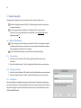
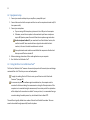
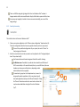
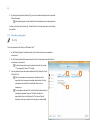
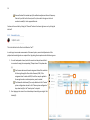
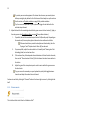
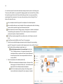
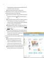
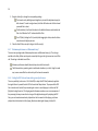
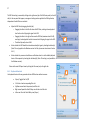
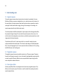
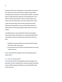
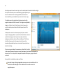
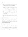
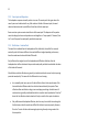
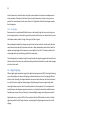
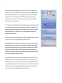
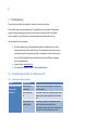
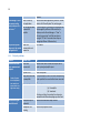
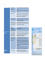
1 User Manual Dirac Live Room Correction Suite™ 2 1 Table of Contents 2 Introduction..................................................................................................................................... 6 2.1 Sound in Rooms ....................................................................................................................... 6 2.2 For Computer Audiophiles ...................................................................................................... 6 2.3 Flexible Playback ..................................................................................................................... 7 2.4 Dirac Live® Technology ............................................................................................................ 7 2.5 About this user manual ........................................................................................................... 7 3 Quick guide ...................................................................................................................................... 9 4 Step-by-step guide ........................................................................................................................ 10 4.1 Software Installation ............................................................................................................. 10 4.1.1 Mac installation ............................................................................................................. 10 4.1.2 Windows installation ..................................................................................................... 10 4.1.3 All platforms .................................................................................................................. 10 4.2 Equipment setup ................................................................................................................... 11 4.3 Using the Dirac Live Calibration Tool™.................................................................................. 11 4.3.1 Sound system setup ...................................................................................................... 12 4.3.2 Microphone configuration ............................................................................................ 13 4.3.3 Output & levels.............................................................................................................. 14 4.3.4 Measurements .............................................................................................................. 15 4.3.5 Filter design ................................................................................................................... 19 4.4 Using the Dirac Audio Processor™ ........................................................................................ 21 4.4.1 Starting the Dirac Audio Processor™ ............................................................................. 21 3 5 4.4.2 Selecting sound card settings ........................................................................................ 22 4.4.3 Making sure DAP is used correctly ................................................................................ 22 4.4.4 Listening to an external source ..................................................................................... 23 4.4.5 Filter selection ............................................................................................................... 24 4.4.6 Setting custom gains and delays ................................................................................... 25 4.4.7 Maximum performance or Minimum latency? ............................................................. 26 4.4.8 Setting the DSP Gain and some other general preferences .......................................... 26 4.4.9 Keyboard shortcuts ....................................................................................................... 27 Understanding more ..................................................................................................................... 28 5.1 Impulse response .................................................................................................................. 28 5.2 Magnitude response ............................................................................................................. 28 5.3 Mixed-phase filters................................................................................................................ 28 5.4 Target curve design guidelines .............................................................................................. 29 5.5 Loudspeakers in rooms ......................................................................................................... 31 5.5.1 Loudspeaker placement ................................................................................................ 31 5.5.2 Sweet spot and dispersion ............................................................................................ 32 5.5.3 Reflections – Good and bad .......................................................................................... 32 5.5.4 Useful tips ...................................................................................................................... 33 5.6 Digital clipping ....................................................................................................................... 33 5.7 Which audio API should I select in the media player for the best sound?............................ 34 5.7.1 Core Audio ..................................................................................................................... 35 5.7.2 ASIO ............................................................................................................................... 35 4 5.7.3 Direct Sound/MME/WaveOut ....................................................................................... 35 5.7.4 WASAPI .......................................................................................................................... 36 5.7.5 Kernel Streaming ........................................................................................................... 36 5.7.6 Asio4All .......................................................................................................................... 36 5.8 6 Recommended reading ......................................................................................................... 36 Troubleshooting ............................................................................................................................ 37 6.1 Troubleshooting the Dirac Live Calibration Tool™ ................................................................ 37 6.1.1 Sound system setup problems ...................................................................................... 37 6.1.2 Playback problems......................................................................................................... 38 6.1.3 Recording problems ...................................................................................................... 39 6.1.4 Filter design problems ................................................................................................... 39 6.2 Troubleshooting the Dirac Audio Processor™ ....................................................................... 39 6.2.1 Account login problems................................................................................................. 39 6.2.2 Playback problems......................................................................................................... 39 Ver. 1.1 DLCT 1.1 DAPC 1.1 Date 2014-09-23 Author NCE 1.0.5 1.0.5 1.0.5 2014-03-29 NCE 1.0.4.1 1.0.4 1.0.4 2013-11-20 NCE 1.0.4 1.0.4 2013-11-06 NCE 1.0.4 Summary Replaced Sound system image on page 12 (192 kHz added and Rescan button moved) Updated instruction for DAP autostart setting Added instruction to point some mics to the speaker Added DSP Gain setting and info that Clip indicator is not available on Mac version Rev. 132 113 112 104 5 1.0.3 1.0.3 1.0.3 2013-04-11 NCE 1.0.2 1.0.1 1.0.2 1.0.1 1.0.2 1.0.1 2012-11-14 2012-07-11 1.0 0.12 0.11 0.10 0.9 0.8 0.7 0.6 0.5 0.4 0.3 0.2 0.1 0.9.26 0.9.26 0.9.25 0.9.24 0.9.21 0.9.20 0.9.20 0.9.20 0.9.20 0.9.20 0.9.18 0.9.18 0.9.17 0.9.39 0.9.39 0.9.38 0.9.37 0.9.34 0.9.33 0.9.33 0.9.33 0.9.33 0.9.33 0.9.32 0.9.31 0.9.30 2012-03-05 2012-02-10 2012-01-13 2012-01-04 2011-12-15 2011-12-08 2011-12-08 2011-12-08 2011-12-08 2011-12-08 2011-11-24 2011-11-21 2011-10-31 NCE NCE VG NCE NCE NCE NCE NCE NCE NCE NCE NCE NCE NCE NCE NCE Added tip to spread out microphone positions Added 4.4.8 Keyboard shortcuts to DAP Added troubleshooting entry Added audio API description Minor edits, 9 measurement points X-ref in quick guide; 8 channel support Corrected sound card multichannel setup Added sound card channel setup details Minor general updates New cover picture New document name Text box adjustments New document name Updates Updates, additional instructions Beta release First draft for comments Copyright © 2011 Dirac Research AB. All rights reserved. 95 90 82 76 75 74 73 72 71 69 68 67 66 65 62 46 6 2 Introduction Thank you for purchasing the Dirac Live Room Correction Suite - the world premier room correction solution for computer audiophiles. Dirac is delighted to offer you this software that is the fruit of many years of experience in sound system tuning and extensive research and development. Please read this manual carefully to get the full performance out of this product. Dirac wishes you many hours of enjoyment listening to your favorite music! 2.1 Sound in Rooms The listening room is usually the weakest link of any sound system: Loudspeakers have been designed for a certain placement and room, but when used in an imperfect room environment, performance suffers. Even the loudspeaker design itself is often a compromise between aesthetics, sound quality, and cost. Imaging, clarity, and bass tightness are examples of properties typically affected by these shortcomings, with the result that music is not perceived as intended by the artist. 2.2 For Computer Audiophiles The Dirac Live Room Correction Suite™ is tailored for computer audiophiles. It optimizes the sound of your particular system to the best possible performance. With the Dirac Live Calibration Tool™ for PC and Mac you can easily measure the acoustic characteristics of your loudspeakers and room, and calibrate them to sound as intended – without unwelcome distortions. The Dirac Audio Processor™, a software application that runs in the background on PC and Mac, then optimizes your sound in real time. 7 2.3 Flexible Playback The Dirac Audio Processor™ filters all the sound that is played from the computer, regardless of the application used – no need for specific media players or plug-ins. Dirac Audio Processor™ is compatible with standard sound cards and computer DACs, so you can enjoy good sound using your favorite applications – always. 2.4 Dirac Live® Technology Dirac Live® is a premium mixed-phase room correction technology used in cinemas, studios, and luxury cars. Unlike the commonplace minimum-phase room correction systems, it corrects not only the frequency response but also the impulse response, a factor critical for accurate staging, clarity and bass reproduction. Dirac Live® will Improve the imaging of your sound system Improve the clarity of the music Make voices more intelligible Produce a tighter bass Reduce listening fatigue Improve the timbre Remove resonances and room modes Reduce early reflections 2.5 About this user manual The Quick guide in the next section lists the main steps to get started with the Dirac Live Room Correction Suite™. For more detailed instructions, refer to the Step-by-step guide starting on page 10, divided into four sections about Software Installation, Equipment setup, Using the Dirac Live Calibration Tool™, and Using the Dirac Audio Processor, respectively. Some important and interesting concepts regarding room correction are described and discussed in the Understanding more section, followed by a Troubleshooting section. 8 If you are reading this document as a PDF file on a computer, then you should be able to click on the underlined links in the text to jump to the referenced section. The same applies for the entries in the Table of Contents. Useful remarks are preceded by this lamp symbol. Warnings and important remarks are preceded by this caution sign. 9 3 Quick guide The following steps will get you started immediately. In the Step-by-step guide on page 10, the process is described in more detail. 1. Run the Dirac Live Calibration Tool™ Installer. (Mac: page 10; PC: page 10) 2. Run the Dirac Audio Processor™ Installer. (Mac: page 10; PC: page 10) 3. Connect your sound card to the computer and the output of the sound card to the input of your sound system (on your amplifier/preamplifier). (page 11) 4. Start the Dirac Live Calibration Tool™. (page 11) 5. Follow the on-screen instructions to select your microphone input and microphone calibration file (page 13), sound card outputs (page 14), measure (page 15) and optimize (page 19) your sound system. Make sure to Save the project regularly to be able to resume your work and fine-tune your settings! 6. When you have saved your filters from the Dirac Live Calibration Tool™, start the Dirac Audio Processor™. (page 21) 7. Select your desired Output device in the bottom of the Dirac Audio Processor™ Controller. (page 22) 8. Click on an empty filter slot (numbered 1-4) and select your newly created filter. (page 24) 9. Make sure that the computer’s primary sound device is set to be the Dirac Audio Processor™. (page 22) 10. Start your media player software (such as iTunes, Spotify, or Windows Media Player) 11. Enjoy a more musical and accurate reproduction of your favorite music! 10 4 Step-by-step guide This guide will go through each step in more detail to achieve the best possible sound. Need more thorough explanations? Refer to Understanding more, where some important concepts are discussed. If you have any problems with the Dirac Live Calibration Tool™ or the Dirac Audio Processor™, then some possible solutions are addressed in the Troubleshooting section beginning on page 37. 4.1 Software Installation If you are using your sound card with your computer for the first time, then please read the installation instructions for your sound card. You may be required to install driver software before plugging the sound card into the computer. It is also recommended to update any sound card drivers before proceeding. 4.1.1 Mac installation 1. Run the Dirac Live Calibration Tool™ installer (.mpkg file) and follow the on-screen instructions 2. Run the Dirac Audio Processor™ installer (.mpkg file) and follow the on-screen instructions 4.1.2 Windows installation 1. Run the Dirac Live Calibration Tool™ installer (.exe file) and follow the on-screen instructions 2. Run the Dirac Audio Processor™ installer (.exe file) and follow the on-screen instructions 4.1.3 All platforms When the installation is completed, the program suite will need to be activated by providing your user license information. You will be prompted to do so when running the software for the first time. Note that the computer has to be connected to the Internet and any active firewalls have to allow HTTP (normal WWW access). 11 4.2 Equipment setup 1. Connect your sound card output to your amplifier or preamplifier input 2. Connect the sound card to the computer and then turn on the computer and sound card (if it has a power switch) 3. Connect your microphone a. If you are using a USB microphone, just connect it to a USB port on the computer. b. Otherwise, connect the microphone to the sound card input. Some microphones require 48V phantom power. Be sure to follow the microphone usage instructions. Avoid microphone feedback! If your sound card has a Direct Monitor function, this must be turned off. Some sound cards have a physical volume knob for direct monitor, in this case it has to be turned down to zero level. Some professional sound cards have sound effects like compression. Double check that any sound effects are turned off. 4. Before continuing, please close all other audio applications on your computer. 5. Start the Dirac Live Calibration Tool™ 4.3 Using the Dirac Live Calibration Tool™ The Dirac Live Calibration Tool™ measures the acoustical properties of the sound system and designs customized Dirac Live® filters for your room and loudspeakers. To apply the resulting Dirac Live® filters to music, you will have to run the Dirac Audio Processor™ (see page 21). As a measure to protect the software against unauthorized use, the computer must be connected to the Internet during the measurements or during the filter optimization. If the computer is not connected during the measurements, then certain parts of the optimization will be delayed until a connection is available. To save your time, it is recommended having a connection during the whole process. Any active firewalls have to allow HTTP. The work flow is logically divided into a number of tabs at the left side of the window. These are meant to be worked through sequentially from the top down. 12 There is a HELP tab along the right edge of the Dirac Live Calibration Tool™ window. It changes content with the active work flow tab. Simply click the tab to open and click to close. Save your project regularly to be able to later resume work and modify your current filter design settings. 4.3.1 Sound system setup This is the first tab in the Dirac Live Calibration Tool™ 1. Choose your system configuration in the “Choose system configuration” drop-down box (A). The system configuration describes how many speaker channels you have in your system. If none of the pre-defined configurations fit your system, then select “Custom” to freely assign up to 8 channels. 2. Select the sound card or device that you want to use for playback in the “Test signal playback device” drop-down box (B). Use the same device and channel assignment that will be used for listening. For Windows users: If available, the preferred choice should be an ASIO device. If ASIO is not available, or if it sounds distorted, then try a non-ASIO device (the same hardware can show up as multiple devices, depending on what audio interfaces its driver supports). If a sound card is grayed out in the drop-down box, it means it is being used by another application. In this case, please close all other audio applications and press the "Rescan" button (C). Clicking the “Rescan” button also searches for sound cards or devices that may have been added after starting the Dirac Live Calibration Tool™. A C B D 13 3. By clicking the sample rate tick boxes (D), you can choose which sample rates the optimized filters will support. Selecting the highest rates will make the filter optimization process take longer time. Continue to the next tab by clicking the “Proceed” button in the lower right corner or by clicking the tab itself. 4.3.2 Microphone configuration This is the second tab in the Dirac Live Calibration Tool™ 1. In the “Recording Device” drop-down box (F), select the device that your microphone is connected to. 2. In the “Recording Channel” drop-down box (G), select the input channel number that your microphone is connected to. If a device shows two (or more) numbered channels, then usually “1” corresponds to Left and “2” to Right. 3. You may optionally load a microphone calibration file by clicking the “Load file” button (H). Only the most expensive measurement microphones can be expected to have transparent recording characteristics. All other microphones can benefit from a calibration file to restore transparency. The microphone calibration file is a text file that should contain the microphone magnitude response. The file format which is supported by Dirac Live Calibration Tool™ consists of lines of <frequency, level> pairs, where the level is given in decibels (dB). F H G 14 Some calibration files instead specify the calibration adjustment for each frequency. Find out if your file has this format, and if so, then switch the signs on the level numbers to modify it to the supported format. Continue to the next tab by clicking the “Proceed” button in the lower right corner or by clicking the tab itself. 4.3.3 Output & levels This is the third tab in the Dirac Live Calibration Tool™ In order to get an accurate measurement of the sound system, some initial adjustments of the playback and recording levels are required. Start by placing the microphone inside the listening area. 1. For each loudspeaker channel, select the sound card output channel that it is connected to using the corresponding “Output channel” drop-down box (J). Use the same device and channel assignment that will be used later for listening through the Dirac Audio Processor (DAP). If the assignments don’t match with DAP, then filters may be applied to the wrong channels or audio output may even be muted. The Subwoofer checkboxes (O) are only editable with the “Custom” system configuration selected in the “Choose system configuration” drop down box (A) in the “Sound system” setup tab. 2. Start playing a test noise in the selected output channel by pressing the Test button (K). M J K L O N 15 To protect your ears and equipment: Turn down the volume on your sound system before pressing the play button for the first time and then slowly turn up the volume. See the section on Playback problems on page 38 for problem solutions. Tip: You can use the space bar of your keyboard to trigger the test button for the selected output channel. 3. Adjust the levels for the recording to be within the green area on the level meter (L). Apply a four-step process (see Recording problems on page 39 for problem solutions): I. If possible, then set the sound card output level to 0 dB (usually max). Depending on the sound card, there may be a physical volume knob or a software level slider. If the sound card driver provides level adjustment functionality, then the “Input gain” and “Output volume” sliders (M) can be used. II. On your amplifier, adjust the volume knob to a “normally loud” listening level. Not disturbingly loud, but not too low either. III. If the volume of any the loudspeaker channel deviates a lot from the other channels, then use the “Channel volume” slider (N) for that channel to make it more similar to the others. IV. Adjust the gain of the microphone input in order to arrive within the green area on the level meter. Tip: you can use the arrow keys on your keyboard to quickly both toggle between channels and adjust the volume for each channel. Continue to next tab by clicking the “Proceed” button in the lower right corner or by clicking the tab itself. 4.3.4 Measurements This is the fourth tab in the Dirac Live Calibration Tool™ 16 It is now time to acquire the acoustical models by measuring the sound system in the listening room. The accuracy of the models is very important for designing optimal room correction filters, so follow the tips below to get the best result. Now would also be a good time to save your project before proceeding with the measurements. You can save the project at any time by clicking the “Save…” button in the lower left corner. Use a microphone stand to firmly place the microphone in the indicated positions. Use a stand that allows you to vary the height of the microphone position within the listening volume, which is important to get an accurate acoustical model. Minimize external noise such as talking, opening or closing doors or windows, and playback of sounds during the measurements. This is to avoid interruption in the measurement process and corruption of acoustical model data. Turn off any computer programs that may make any noise, such as Skype or your email client. Turn off any sound card effects such as “low-cut” or compression. 1. Select the most suitable listening environment preset by clicking on the corresponding graphic (P). In general, it is important to collect measurements in the most likely “listener’s head” positions (sitting, standing, leaning forward, etc.). Avoid making measurements in a too small space. Even for the “Chair” listening environment, it is important to spread out the microphone positions in a sphere of at least 1 meter of diameter. A too small space will result in over-compensation that will sound very dry and dull. 2. Place the microphone in the indicated position (Q). The first measurement should always be taken in the center of the listening region, in the desired “sweet spot”, as this will be used for alignment of levels and delays between loudspeakers. Direct the microphone upward, pointing to the ceiling, to get the most omnidirectional recording of the room response, or towards P S Q R 17 the speakers depending on the particular microphone and its calibration file (if any). Please follow the instructions from your supplier. Use the view selector (R) to better localize the microphone positions. 3. Press the Start button (S) to collect a set of measurements. This will play a sweep in each loudspeaker and one final sweep in the first loudspeaker again. If the measurement was successful, then the position indicator will move to the next spot. Repeat the procedure from step 2 above until nine (9) positions have been covered. If your sound card or microphone pre-amplifier has a clip indicator, then keep an eye on the microphone input. If it clips during measurement, then re-take that measurement. (Usually, the clipping will be detected by the DLCT, but depending on level settings, the clipping event may fail to be detected.) If the measurement failed, then usually an error message will be given. Follow the instructions in the error message, or refer to the troubleshooting section Recording problems on page 39. Tip: You can click each measurement point (T) to view its recorded sequence in the graph (U). You can also delete individual measurements by clicking the red cross (X) that appears when the measurement point is marked. Doing so will allow you to retake that individual measurement. 4. After nine positions have been measured, there is enough data to design a set of filters. Using the microphone positions indicated by the Dirac Live Calibration Tool™ will generally give you consistent results. However, the microphone positions are not required to be in exactly these positions - if your listening environment looks different then you may use a different set of microphone positions. Taking all measurements close to the sweet spot will generally not give optimum performance because the microphone positions need T X U 18 some spread in order to acquire enough acoustical information about the room. Don’t forget to save the project before proceeding, just to be safe. Continue to the next tab by clicking the “Proceed” button in the lower right corner or by clicking the tab itself. 19 4.3.5 Filter design This is the fifth and last tab in the Dirac Live Calibration Tool™. The filter design algorithm uses the measured data together with a target frequency response to calculate filters that optimize the frequency response and the impulse response of the sound system. Finding the best target frequency response may require a little experimenting from your side. After completing the measurements, the Dirac Live Calibration Tool™ will automatically generate a suggested target curve that matches the measurements. This, however, can often be tweaked for even better performance. The filter design algorithm has a hard-coded maximum gain value that limits the boost at any frequency. 1. There are two ways to modify the frequency response: i. Dragging the target frequency curve at the anchor points (a). ii. Dragging the frequency limits on either side of the frequency range (b). Refer to Target curve design guidelines on page 29 for advice on how to design a good target response. The resulting filter will leave the audio signal unmodified in the shaded frequency regions. This can be useful if you, for example, are perfectly happy with the high frequency performance, but want to address room resonances in the bass. It is possible to add (or delete) anchor points by double clicking on the target curve (or on the points). The zoom level is shown at the top of the graph (c). To zoom in, draw a box around the area that you would like to zoom into. h c i a e a a d b b f g l j 20 To zoom back to the previous level, click on the minus sign next to the zoom level (c) or double-click in the graph. To view the impulse response of the system, before and after correction, click on the “IMPULSE” button (i). In the impulse response view, this button will change its label to “SPECTRUM” and clicking on it will take you back to the frequency view. It is possible to set a target curve for all channels at once, a linked group of channels, or one channel at a time. Use the channel tabs (d) on the right side of the plot area to change the grouping configuration. i. Clicking on the chain symbol of a channel tab (e) causes the channel to detach from the linked group and showing the detached channel’s curve in the plot area. You can also drag and drop to unlink. ii. Dragging and dropping a detached channel tab onto a linked channel tab causes the detached channel to join the group and show all the grouped channels’ curves in the plot area. 2. Press Optimize (f) to create a set of filters. 3. When the optimization has completed (this may take some time depending on the speed of your computer and how many sampling rates you selected to make filters for), press “Save Filter” (g) below the target editor to save the filter to a file that you will be able to open in the Dirac Audio Processor™. To be able to load the filter in the Dirac Audio Processor™, make sure to save it in the default directory suggested by Dirac Live Calibration Tool™: Windows 7/Vista: C:\Users\<user>\AppData\Roaming\Dirac\Filters Windows XP: C:\Documents and Settings\<user>\Application Data\Dirac\Filters Mac: ~/Library/Application Support/Dirac/Filters (NOTE: As of Mac OS X Lion (10.7) the Library folder is hidden. Press the function key while in the Go menu in Finder to find it.) 4. To design a new filter for the same sound system, repeat the procedure from step 1 above. To design filters for a different sound system, then go back to the Sound system tab and follow the instructions from Sound system setup on page 12. Linked Detached 21 Saving a project once a target curve has been set will save the state of the target curve in the project. If you are testing several target curves it may be a good idea to save each target with the Save Target button (j). This will allow you to revisit and tweak the target curves from which a specific filter has been generated by loading them with the Load Target button (l). Loading a target will apply it to the currently visible channel (group). Please note that there are two save buttons with different functions, one for saving the filter “Save Filter” (g) and one for saving the project “Save…” (h). 4.4 Using the Dirac Audio Processor™ The Dirac Audio Processor (DAP) is a “virtual sound card” that applies Dirac Live® filters to an audio stream. The audio stream is directed to the DAP by the computer’s operating system by setting DAP as the default playback device. 4.4.1 Starting the Dirac Audio Processor™ Once installed, the DAP should be launched automatically upon system startup. If the DAP has been set to not start automatically at login, then it can be started as follows: In Windows: From the Windows Start menu -> All programs -> Dirac -> Dirac Audio Processor -> Dirac Audio Processor Controller Once running, clicking the “D” icon in the taskbar notification area opens the DAP Controller window. On a Mac: From the Applications folder -> Dirac -> Dirac Audio Processor Once running, clicking the “D” icon in the dock opens the DAP Controller window. Tip: If you have set the DAP not to start automatically upon system startup, you may want to drag the DAP application icon from the Applications folder into the dock for easy startup in the future. 22 If you don't want DAP to start automatically when logging in to the computer, then change its settings by: In Windows: Use DAP settings view as described in Section 4.4.8. On a Mac: 1. In the Apple menu, select “System Preferences…” Then click the “Users & Groups” icon under the “System” section of the System Preferences window. Note: in older versions of OS X You will have to click the “Accounts” icon instead of the “Users & Groups” icon. 2. In the “Login Items” tab of the “Users & Groups” (or “Accounts”) settings window, click to highlight the “Dirac Audio Processor” item. n 3. Below the selection window, press the “–“ (minus) button. 4. Close the window. 4.4.2 Selecting sound card settings At the bottom of the DAP Controller window, open the “Device settings” tab (k). In the “Output device” drop down box (m), select the sound card where you want to output the filtered audio signal. This will simultaneously set the DAP as the default playback device for the computer. It should now be possible to launch a media player application on the computer to test the DAP functionality. Once the player starts playing, the “Streaming” indicator (n) on the upper right of the DAP should be lit. k m 4.4.3 Making sure DAP is used correctly In Windows and Mac, the Dirac Audio Processor™ will be automatically set as default device. However, it may be necessary to double-check this. Please follow the instructions below for your OS: 23 Windows: 1. Open the Sound control panel by right-clicking the “D” icon in the taskbar notification area and selecting “Open Control Panel (Sound)”. 2. In the “Playback” tab of the Sound control panel, verify that the device labeled “Dirac Processor” is selected. If it is not, then select it and click the “Set Default” button. 3. For multichannel use: a. Click the “Configure” button. . b. In the “Speaker setup” window, ensure the required channel configuration is selected and click “Next” twice and finally “Exit” to store the configuration. 4. Click OK or Apply to apply a change, or Cancel to exit without changing. Mac: 1. In the Apple menu, select “System Preferences…” Then click the “Sound” icon under the “Hardware” section of the System Preferences window. 2. In the “Output” tab of the “Sound” settings window, verify that the device labeled “Dirac Audio Processor” is selected. 3. Close the window. 4. For multichannel use: a. Audio MIDI Setup is in the “Utilities” folder inside the “Applications” folder. Open it and click on the “Audio Devices” tab. b. Ensure that at least the required number of channels is selected for the Dirac Audio Processor device c. Click on “Configure Speakers...” to check and possibly configure which output channel that is routed to which speaker. 4.4.4 Listening to an external source With some operating systems, it is possible to also process the sound from an external source, such as a CD player or iPod. 24 Listening to an external source is not a fully supported feature in the Dirac Audio Processor. It is only under certain circumstances that this functionality can be achieved. Warning: Do not activate this feature with a microphone plugged into the input of the device that is used for the external source. This may cause very high sound pressure levels due to feedback. Windows 7 (stereo only): 1. 2. 3. 4. 5. 6. 7. 8. Connect the external source output to a sound card input Open the Sound control panel as described in Making sure DAP is used, above. In the Sound control panel, select the Recording tab Select the sound card input that the external source was connected to Click the Properties button In the Properties window, select the Listen tab Check the “Listen to this device” checkbox Press OK or Apply Mac: 1. Connect the external source output to a sound card input 2. Use the free application LineIn by Rogue Amoeba or similar to feed the sound card input into the Dirac Audio Processor™. LineIn can be downloaded at: http://www.rogueamoeba.com/freebies/ 4.4.5 Filter selection Filter sets created for the Dirac Audio Processor™ by the Dirac Live Calibration Tool™ can support up to 8 channels each. The Dirac Audio Processor™ has four (4) pre-selection slots where filter sets can be loaded for quick selection. To load a filter set into an empty slot: 1. Click on an empty filter slot. This opens a popup menu with available filter sets. x 25 z 2. Select the filter set that you want to load from the popup menu. If the filter set is already loaded in another slot, it will be unavailable for loading. If the filter set is not compatible with the selected output device, in terms of number of required channels or supported sampling rates, then it will load but remain disabled until a compatible output device is selected. y Listen to the result of applying the loaded filters: 1. Start a media player on the computer and play a track. 2. Make sure that the “Filter” switch (x) on the DAP is set to “On”. 3. Switch between loaded filters by clicking the corresponding filter slot. Unload a filter set from a slot: 1. Click on the trashcan icon (y) 2. Confirm the unloading in the pop-up window by pressing Enter or clicking the “OK” button. 4.4.6 Setting custom gains and delays Clicking the small arrow on each filter slot (z) brings up the Gain & Delay settings for the filter loaded in that slot. Here you can adjust the Gain (that is, the volume) of each loudspeaker channel and also the delay of each channel. r The delay and gain values for each channel are automatically configured by the Dirac Live Calibration Tool™, so in most cases you are not required to adjust them. t In a stereo setting, increasing the delay for a loudspeaker will move the center image away from that loudspeaker towards the other loudspeaker. In a surround setting, it can be useful to fine tune the gain and delay difference between the front loudspeakers and the surround loudspeakers. 1. Open the Gain & Delay control panel for a filter by clicking on the right-arrow icon corresponding to the filter set (z). 2. Enable the Gain & Delay settings by toggling the “Enabled” switch (r). s u v 26 3. Drag the sliders (s) to change the corresponding settings. The channels are by default grouped together in pairs and the adjustments apply to both channels. To select a single channel, hold the shift button and click the channel you would like to select. The Reset button (t) will reset the values to the defaults that were calculated by the Dirac Live Calibration Tool™ and saved with the filter. On a PC (Mac), holding the Ctrl (control) while dragging the sliders, make the sliders move slower with higher precision. 4. Close the Gain & Delay view by clicking on the left arrow (u). 4.4.7 Maximum performance or Minimum latency? There are two operating modes: Maximum performance and Minimum latency (v). The setting is available in the Delay & Gain control panel, accessed by clicking on the right-arrow icon in each filter slot. The setting is individual to each filter. Maximum performance should (almost) always be used for best results. The Minimum latency operating mode is useful when low latency is critical. Using this mode may in some cases affect the relative delay of the channels somewhat. 4.4.8 Setting the DSP Gain and some other general preferences There is a possibility (as of version 1.0.4 of the DAP) to adjust the DSP Gain (headroom) applied to the signal before it is passed from the DAP to the selected Output device. The purpose of the DSP Gain is to reduce the level of the processed signal in order to avoid clipping at or before the DAC (Digital-to-Analog Converter). This clipping would otherwise sometimes occur as a consequence of the processing that may increase the level range of the digital audio signal. By adjusting the DSP Gain, you can choose between louder playback level with increased risk for clipping, and, lower playback level with reduced risk for clipping. Read more about digital clipping in Section 5.6. 27 The DSP Gain setting is accessed by clicking on the right arrow (aa) of the DAP main panel (on the left side). In the new panel that appears, some general settings can be applied to the DAP application, independent of which filters are selected: Adjust the DSP Gain by dragging the slider (ab). o Dragging the slider to the left will reduce the DSP Gain, resulting in lower playback level but less risk of clipping the signal in the DAC. o Dragging the slider to the right will increase the DSP Gain (maximum level is 0 dB), resulting in louder playback level but increased risk of clipping the signal in the DAC. o The default (normal) value is -8dB. Select whether the DAP should be started automatically at logon by checking checkbox (ac). (Note: This only applies to the Windows version. For Mac, please see instructions in Section 4.4.1.) Select whether the processor should show a notification when it is not the default playback device of the computer by checking the checkbox (ad). (Note: This setting is only available in the Windows version.) aa Return to the main DAP panel view by clicking the left arrow (ae) on the right side. 4.4.9 Keyboard shortcuts Use keyboard shortcuts for easy operation of main DAP functions without a mouse: ab 0 (zero): Toggle Filter On/Off 1-4: Select or load corresponding filter slot Up/Down arrow: Switch to previous/next filter slot Right arrow: Expand the Gain & Delay view for the active filter slot Left arrow: Close the Gain & Delay view (if open) ac ad ae 28 5 Understanding more 5.1 Impulse response The impulse response measures how a transient such as a drum beat is reproduced in the room. Reflections, diffraction, resonances, misaligned drivers, etc., combine to smear out the transient. As the name indicates, the impulse response shows how the system and room responds to an impulse input signal. An ideal speaker adds no ringing, coloring, or time smearing to the recording, so its impulse response should look just like the input impulse. The similarity between the different loudspeakers’ impulse responses at the listening position affects the perception of stage and image. The more similar the impulse responses, the more easy it is to trick the brain that the loudspeakers are not really there, and that the sound emanates from a virtual stage spanned by the physical speakers. The performance of Dirac Live® is quite unique in that it is so successful in making the system response resemble that of an ideal speaker. This is thanks to robust design of so-called mixed-phase filters. The result of applying Dirac Live® can be viewed in the Dirac Live Calibration Tool™, by clicking the IMPULSE button in the Filter Design tab. 5.2 Magnitude response The magnitude response (a commonly used but imprecise term is “frequency response”) measures how much each frequency component, or tone, is attenuated. A good magnitude response should be as smooth as possible. Otherwise, different tones are reproduced with unequal strength, and the music is subjected to undesired coloration. 5.3 Mixed-phase filters Infinitely many different filters can be designed to have the exact same magnitude response. They differ only in their impulse response. Therefore, it is useful to classify filters according to how their impulse responses behave. 29 Two commonly used filter classes in audio applications are minimum-phase filters and linear-phase filters. They are two special cases that are relatively easy to design, but that come with tightly constrained impulse response characteristics. A minimum-phase filter, by definition, is constrained to apply only the smallest possible delay to the signal given a desired magnitude response. A linearphase filter, by definition, applies a delay which is constant across the whole frequency range. Therefore, neither of these two filter designs can make a desired change to the phase or impulse response, unless the desired change is exactly the particular change they make by definition. Minimum-phase and linear-phase filters may even worsen both the impulse response and the magnitude response of a system, simply by applying their magnitude response corrections at the wrong time. A more difficult design task is to make a mixed-phase filter that matches a desired magnitude response while also having a customized impulse response. A properly designed mixed-phase filter can make significant improvements to the impulse response of a sound system at the listening position: Misaligned drivers in multi-way loudspeakers can be corrected by automatically applying different delays to different frequency ranges. Energy from direct wave and early reflections can be optimally combined to arrive as a single wave-front to the listener. Dirac Live® uses mixed-phase filters to optimize the impulse response while applying a desired magnitude response. 5.4 Target curve design guidelines In the Dirac Live Calibration Tool™, the desired magnitude response for each loudspeaker can be drawn manually. The reason for providing this feature, instead of just optimizing for a flat magnitude response, is that different loudspeakers and different rooms may require slightly different target curves for the best result. 30 Normally you want to have the same target curve for identical pairs of channels like the left and right front speakers. Therefore, these are automatically grouped together by the Dirac Live Calibration Tool™. Correcting for differences between the channels will often give a substantial improvement in the stereo image. The shaded regions in the target editor illustrate regions where the magnitude response will be left untouched. These regions are adjustable by dragging in the handles on the shaded regions. Normally you want to correct the whole spectrum that is within the frequency limits of the loudspeaker. All loudspeakers tend to have a low frequency limit, below which the response is dropping rapidly. It is important to not boost the bass too much under this low frequency limit, because it can easily overdrive the loudspeakers and lead to distortion. Dirac Live Calibration Tool™ tries to identify the frequency where the response starts to drop and the automatically generated target curve and correction frequency limits are adjusted accordingly. If there is noise present during the measurements, this will often be visible in the measured frequency response as increasing low frequency levels below the loudspeaker low frequency limit. This is not part of the loudspeaker response so this frequency region is better left untouched. Some guidelines to adjusting the target curve follows: Even small changes in the target magnitude response give more or less audible results. It is worthwhile to tweak the target in order to address even the smallest nuance in the magnitude response. 31 Avoid sharp peaks in the target curve, as they may result in annoying tonal components in the frequency response. Generally you want to have a smooth target curve. A target curve that is slightly tilting down towards high frequencies (like the auto-target) is often preferable - a flat target often sounds too bright. A loudspeaker with a flat on-axis response will usually have a slightly tilting in-room response. You can experiment with the amount of tilt, especially in the treble region, to get a good timbral balance in your room. If you have strong room-resonances in the low frequency region, completely eliminating these may make the sound thin in comparison. You may want to apply a slightly increasing low-end below 100 Hz. If you have dips in the magnitude response, sometimes it sounds better to not fill these in completely. 5.5 Loudspeakers in rooms The topic of sound reproduction in small rooms, such as a living room as opposed to a concert hall, is huge. The room will define how reproduced music is perceived. Roughly, the effect of the room on the sound can be divided into two parts - the effect on frequency response (timbre, coloration) and the effect on spatial aspects of sound (spaciousness, envelopment, reverberation). Both parts are affected by speaker placement and listener position. 5.5.1 Loudspeaker placement Correct placement of the loudspeakers in your room is vital to get the best possible sound. Therefore it is often worthwhile to experiment a bit with the loudspeaker placement. Always use the speaker manufacturer recommendations as a starting point. Using Dirac Live®, you have more freedom in loudspeaker placement, although the best result will still be achieved with the optimal loudspeaker placement in combination with Dirac Live®. 32 5.5.2 Sweet spot and dispersion The loudspeaker response varies with position in a room. The sweet spot is the region where the sound is perceived as best and with very little variations. Outside of the sweet spot, the sound character deteriorates and is quite different from that within the sweet spot. Room correction systems cannot extend the size of the sweet spot! The dispersion of the speaker cannot be changed, unless several speakers are used together as a ”super speaker”. However, Dirac Live® can still improve the sound quality outside the sweet spot. 5.5.3 Reflections – Good and bad The sound that is radiated from the loudspeakers will be reflected by the walls of the room and eventually reach the listener at different times and at different angles, depending on how many times the sound wave has been reflected off the walls. Early reflections from angles close to the loudspeaker and diffraction reflections from the loudspeaker box itself are detrimental to perceived sound quality and lead to undesirable coloration of the timbre of the sound. Side reflections and late reflections are generally not as detrimental and can even help in improving perceived sound quality. The reason for this difference lies in our hearing: In a reasonably sized room, we can tell a side reflection from a direct wave because of the time and direction differences which our brain has learned naturally to separate. These reflections often contribute to a larger, more enveloping sound stage. A small amount of reverberation is generally considered desirable in a room for sound reproduction. Dirac Live® leaves the late reflections almost untouched. It only corrects for their spectral coloration. Early reflections and loudspeaker diffraction, which are very close in both time and angle to the direct wave, make the sound more difficult for the brain to process properly. However, Dirac Live® corrects for these shortcomings by optimizing the early arriving sound at the listener position. 33 At bass frequencies, room reflections may build up and create what is known as standing waves or room resonances. Characteristic of these is that at certain frequencies, the bass is strong in some parts of the room and weak in other parts. Dirac Live® mitigates the effect of standing waves inside the listening area. 5.5.4 Useful tips Room acoustics is a complicated field but there are a few simple things that one can do to improve the listening experience. Generally it is good to have quite much furniture on the walls and try to use soft furniture where possible. A large, thick rug on the floor is good. Many loudspeakers benefit from being moved out from the front wall a bit, and also to be placed at some distance from side walls. Experiment with toe-in: Many loudspeakers sound the best with the speakers pointing straight at the sweet spot or even slightly in front of it. This helps to stabilize the stereo image when you are listening outside of the sweet spot. The listening location is important as well, having the sofa placed right up against the back wall is not ideal since there will be very early reflections coming from behind and also the sound timbre changes a lot close to the walls. 5.6 Digital clipping When a digital signal exceeds the range of the digital-to-analog converter (DAC), then digital clipping occurs. Depending on the amount of clipping, and what information is lost in the clipping, different artifacts result. Generally, the clipped waveform causes non-linear distortion, which can be heard as a scratch-like noise in high-level audio passages. Digital clipping of the source signal simply adds some high frequency content, which is usually harmless for the equipment. It is for example more harmful to pass a low frequency signal to a tweeter, or to electrically saturate the amplifier output. Depending on how sensitive your hearing is, occasional digital clipping can usually pass unnoticed. Digital audio sources, such as DVD or CD, are recorded with the DAC limitation in mind, so that the signal stays within the DAC range. However, any boosting of the digital signal increases the risk of clipping. 34 If digital clipping is detected in the Dirac Audio Processor (DAP), then the Clip indicator (af) in the DAP Controller™ is lit for a short moment (the Clip indicator is only available in the Windows version of the DAP, not in the Mac OSX version). If the digital clipping is disturbing, then try reducing the playback volume in the media player (the input to the DAP) and possibly compensate this by increasing the volume in the amplifier. An alternative fix is to adjust the DSP Gain of the DAP by following the instructions in Section 4.4.8. 5.7 Which audio API should I select in the media player for the best sound? This is a rather complicated question, so let us go through some key concepts. The audio API is the programming interface that the media player uses to send audio to the sound card, in this case DAP which could be called a “virtual” sound card since it is a piece of software which is seen by the Operating System as a sound card. The Audio API is provided by the Operating System and is the link between the media player and the sound card driver, which in turn communicates directly with the hardware. Different applications like your media player, internet browser etc. may stream sound to the sound card simultaneously, so the Operating System must provide some functionality for mixing together audio streams from different applications. To complicate matters, the audio streams from different applications may have different sample rates. Since the sound card can only operate at a single sample rate at a time, the audio streams that have a different sample rate than the sound card is set to will have to be resampled by the operating system. It is generally desirable to avoid resampling by the operating system because the quality of the OS sample rate converter may not be very good. Which audio API is chosen in the media player for sound output affects if sample rate conversion is likely to take place. On the Mac platform there are only two audio APIs to choose from, but on PC platforms there are several. Sometimes the operation of the sound card driver is not bug-free with all audio APIs (artifacts in the sound like glitches etc. may occur) and in that case trying a different API may solve the problem. af 35 The sound card can be operated either in shared mode or exclusive mode. If the sound card is opened in shared mode by the media player, then other applications are allowed to use the sound card as well and the above reasoning about operating system mixing and resampling applies. If the sound card is opened in exclusive mode by the media player though, then no other application can use the sound card and there will be no resampling since it is the media player that decides which sample rate the sound card shall use. It is set to the same sample rate as the currently playing media file has. 5.7.1 Core Audio Core Audio is the only audio API provided by the OS on Mac computers. Both shared mode and exclusive mode sound card access is supported. Take care to set the output format of Dirac Audio Processor in Audio/Midi-settings to use the same sample rate as the music source material, if not using exclusive sound card access. 5.7.2 ASIO ASIO is a type of sound card driver used mainly by studio-grade sound cards and is designed for lowlatency synchronous playback and recording. ASIO is available both on Windows and Mac computers, provided that the sound card driver supports it. ASIO interfaces directly with the sound card driver, without intervention from the operating system. ASIO cannot be used directly to stream sound to the Dirac Audio Processor, although a third party driver like Asio4All (described below) can be installed to enable use of the ASIO output mode in a media player. To decrease the hassle, use WASAPI or Kernel Streaming instead if it is available. 5.7.3 Direct Sound/MME/WaveOut These are standard higher level APIs in Windows. They use shared mode, so that all audio streams are mixed together and sent to the sound card in a single format that is configurable (in terms of number of channels, sample rate and bit-depth) in the sound control panel. These APIs are only recommended as output mode if the shared mode sample rate is set in the sound control panel to the same sample rate as the audio files to be played back. 36 5.7.4 WASAPI WASAPI is a low-level audio API available on Windows Vista/Windows 7 and newer. It allows bypassing all processing by the operating system and can be used for exclusive access to the sound card (DAP). WASAPI can be used in both exclusive mode and shared mode. Using shared mode with WASAPI differs logically from higher level APIs like Direct Sound because the audio stream will not be resampled by the operating system, but rather by the media player if needed (if the media player supports resampling). Using WASAPI as output mode (preferably with exclusive sound card access) is recommended on Windows Vista/Windows 7 if your media player supports it. 5.7.5 Kernel Streaming Kernel streaming is a way to access the sound card bypassing the operating system mixer/resampling. It is available in Windows 98 and newer. Kernel Streaming is a recommended output mode on Windows XP and older, on Windows Vista and newer WASAPI is recommended instead since it is a more modern protocol. 5.7.6 Asio4All Asio4All is a piece of software that lets you use the ASIO output mode of e.g. a media player to send audio to virtually any sound card device even if it does not support ASIO to begin with. Asio4All does this by emulating an ASIO device and basically using Kernel Streaming to talk to the sound card driver. Most often there will not be any clear benefits of using Asio4All if the media player already supports playback directly via Kernel Streaming/WASAPI/ASIO. 5.8 Recommended reading For the interested reader, a good book for learning more about how loudspeakers and rooms interact and how to achieve good sound is "Sound Reproduction, Loudspeakers and Rooms" by Floyd E. Toole (2008). 37 6 Troubleshooting If you run into any trouble, then please first refer to the common errors below. If the problem remains, we would appreciate it if you would send us a description of the problem, perhaps including a supporting screenshot, and also provide information of the Dirac software version, computer type and OS version, and soundcard type and soundcard driver version. You can contact Dirac in several ways: Click the Feedback link in the bottom edge of the Dirac Live Calibration Tool or on the bottom right side of the Dirac Audio Processor. This automatically collects the necessary information except for the problem description. No information is sent to Dirac until you press the “Submit Feedback” button, and all information that will be sent is displayed within the Feedback form. Send an email to [email protected]. Fill in and submit a support request on http://helpdesk.dirac.se. 6.1 Troubleshooting the Dirac Live Calibration Tool™ 6.1.1 Sound system setup problems Problem Possible Cause Sound card device does Sound card cable not show up in disconnected selection list Sound card power is OFF Sound card driver not installed properly Fix Connect a suitable cable between the sound card and the computer. Some sound cards require a separate power source. Connect a power source and switch on the sound card First, attempt a restart of the computer with the sound card connected and switched on. If the problem persists, then refer to the manual of the sound card to re-install the device driver 38 Error message: “Could not open recording device, make sure it is not in use…” Only Custom system shows up in the system configuration list software. Device is in use by Close all other audio applications, press the “Rescan” other application button in the “Sound System” tab, and try again. Two USB devices share Try connecting one of the devices to a different USB the same USB port managed by a different USB controller. (In controller Windows, see the Device Manager -> “View” -> “Devices by connection” and find your devices among the “PCI bus” items and ensure they are managed by different USB controllers.) Sound card See fix above disconnected or not powered on 6.1.2 Playback problems Problem Possible Cause No sound from level Audio cable test or measurement disconnected playback Amplifier is OFF Wrong source selected Caution: To protect on preamplifier ears and equipment, never switch on or connect devices at a high volume setting! Measurement signal sounds distorted Volume too low Preamplifier input is overloaded Loudspeakers are distorting Fix Connect audio cable to sound card output and to sound system (pre)amplifier input Switch on amplifier On the preamplifier, select the source corresponding to the input that the sound card has been connected to Increase volume on (a) Preamplifier (b) Sound card If this does not help, then reduce the volume to a reasonable level before attempting any other fixes! Decrease the sound card output volume Decrease the playback volume 39 6.1.3 Recording problems Problem Possible Cause Level test meter does Microphone not react disconnected Switch off sound playback while attempting to fix this problem. Instead, clap your hands or make some other sound to detect a reaction on the level meter. Measurement does not complete successfully Microphone needs phantom power Microphone preamplifier is OFF Error message 6.1.4 Filter design problems Problem Possible Cause Filter optimization Client is offline does not complete Firewall is blocking access Fix Connect microphone to microphone preamplifier and connect microphone preamplifier to sound card or to computer. Enable the 48 V phantom power on the microphone preamplifier input. Depending on the microphone preamplifier, this could be a physical button or a software setting. Switch on microphone preamplifier Follow instructions given in the error message. Fix Connect the client computer to the web Disable firewall or set it to allow HTTP traffic 6.2 Troubleshooting the Dirac Audio Processor™ 6.2.1 Account login problems Problem Possible Cause Validation server is not Client is offline accessible Firewall is blocking access 6.2.2 Playback problems Problem Possible Cause Fix Connect the client computer to the web Disable firewall or set it to allow HTTP traffic Fix 40 Sound is not clean Audio device driver needs updating Sound is clipping Sound card has a sound effect enabled Media player cannot play sound Output sounds unfiltered Sound card is running at a different sampling rate than the original music Audio sounds compressed and playing at a low level Another application is using the sound card and the "Streaming" indicator is shining. Channel assignment in DLCT does not match DAPC channels DAP is not running “Filter” is set to “Off” Update your playback device driver to latest stable version. Sometimes, there may be new drivers that have issues. Adjust the volume on the media player or reduce the DSP Gain until the “Clip” indicator stops flashing (“Clip” indicator is not available on Mac) Disable all sound card sound effects. This may either be a physical setting on the sound card or a driver setting in the operating system. If the sound card has sample rate selector, either physical or in software, choose the same sample rate as the music files you are playing. The DSP Gain is too low. Refer to section 4.4.8 for adjustment instructions. Close all other applications that are using the sound card. If necessary, restart both the media player and Dirac Audio Processor. Start the Dirac Audio Processor before the media player. The filters are designed for the channel numbers assigned in DLCT. If the output device selected in DAPC uses other channel numbers (see example picture on the right), then the output from channels without filters will be muted because audio is routed to the channels that correspond to the DLCT setting for these filters. Use the same device and channel assignment for listening in DAPC as in the DLCT measurements. Windows: Launch DAP in the Start menu. Mac: Launch DAP from the Applications folder. Open the DAPC and set “Filter” to “On” in DAPC 41 “Filter” is set to “Off” in DAPC and cannot be switched to “On” Dirac Audio Processor does not show up in Sound control panel in DAPC The sampling rates do not match between the filter and the output device. Some drivers are not fully compatible Try changing the output device sampling rate, using the operating system Sound control panel, to one that the filter supports. There are some possible workarounds, listed in order of simplicity: Re-start the Dirac Audio Processor: o Exit the Dirac Audio Processor by right-clicking the D icon and selecting “Exit Controller”. o Ensure the process diracapsrv.exe is not running in the Processes view in Task Manager. If still running, End it. o Start the DAP again via the Start menu. Disable the physical sound card during installation of the Dirac Audio Processor: o Disable the problematic sound card in the Sound Control Panel Right-click on the “D” icon and select “Open Control Panel (Sound) Select the “Playback” tab Right-click the slot that corresponds to the physical sound card and select “Disable”. o Uninstall DAP via the Start menu o Install DAP from the download file. o Enable the physical sound card again (make sure you select the option “Show Disabled Devices” to see a 42 o disabled device) Select the physical sound card as Output device in the DAPC.