1
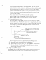
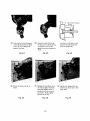
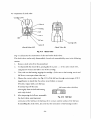
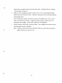
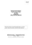
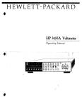
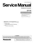
228-10832A
Solvent Delivery Module
LC-6A
for
The Shimadzu High Performance
Liquid Chromatograph
Service Manual
SHIMADZU CORPORATION
ANALYTICAL INSTRUMENTS DIVISION
KYOTO. JAPAN
Contents
1.
Introduction
1
2.
Specifications
2
3.
Construction and Function
3
3.1 Front panel
3
3.2 Rear panel
5
3.3 Left side panel
6
3.4 Flow line
7
3.5 Solvent delivery pump main unit
9
3.6 Electrical system
4.
5.
11
3.6.1
Checking connector
11
3.6.2
Relation between deformed cam rotating angle and pulse
14
3.6.3
Usage of the REMOTE connector
15
3.6.4
Circuit diagram
19
Maintenance
22
4.1 Inspection of clogging and stains and cleaning of LC flow line
22
4.2 Replacement of plunger seal
23
4.3 Replacement of line filter
25
4.4 Zero point adjustment of pressure sensor
25
4.5 Lubrication of the moving parts of the pump
25
4.6 Inspection of check valve
26
Troubleshooting
28
5.1 General troubleshooting
28
5.1.1
Large drift and noise are generated on the base line
28
5.1.2
Even when samples are charged, no peak is produced
29
5.1.3
Peak retention time changes, abnormally short or abnormally long
30
5.2 Solvent delivery flow rate is unstable, and solvent delivery flow pulsation
is noticeable
5.2.1
Checking method
5.2.2
Cause and remedy
5.3 No pump performs high-speed suction operation
31
31
.
31
34
5.4 Flow rate at no load does not fall within the specification with respect to
the present value
35
5.5 Abnormal noise is generated from one pump
36
5.6 Sample symptoms for pressure base
36
5.7 Checking circuit
38
1.
Introduction
This Service Manual is intended for users operating this equipment, and describes the maintenance
method for Type LC-6A solvent delivery module for Shimadzu high performance liquid chromatograph.
Explanation is given mainly of a general troubleshooting for malfunctions which are apt to take
place during operation, maintenance and check points for routine work and detailed construction
of this equipment.
Regarding electronic circuits such as printed circuit boards, this manual merely shows the circuitry
explanation and circuit diagram, no explanation is given if elements such as IC's and transistors.
When performing operation, use this manual together with the instruction manual. With due care
taken for installation hints for equipment operation and operating precautions, you are required
to carry out adequate and more effective maintenance of this equipment.
- 1-
2.
Specifications
1.
Single small plunger reciprocating pump of constant
Pump
discharging and quick suction type (100ju£/stroke)
2.
\l)
Mode of delivery
Constant flow or constant pressure delivery
Constant flow delivery
o Range of flow rate
0.1 ~ 5mfi/min. (10 ~ 500kgf/cm2)
0.1 ~9.9m£/min. (10 ~ 250kgf/cm2)
o Accuracy of flow rate setting
Within ±2% or 20/u£/min., which is higher (0.1 ~ 5m£/
min.)
o Stability of flow rate
Within ±0.5% (within the 0.1 ~ 5m£/min. range)
Constant pressure feeding
o Pressure setting range
10 ~ 500kgf/cm2 (at 10kgf/cm2 intervals)
o Accuracy of pressure setting
Within ±20% of the setting or ±25kgf/cm2 , whichever is
smaller
3.
Pressure limit setting
o High pressure limit
0 ~ 500kgf/cm2 continuously variable
o Low pressure limit
OFF, 0 ~ 300kgf/cm2 continuously variable
4.
Pressure indicating range
0 ~ 500kgf/cm2
5.
Dampener
Flow-through type with interval capacity of 1300/x£
6.
Materials in contact with solvent
SUS316, Hastelloy C, ruby, sapphire, Kel-F, Teflon
tempered with graphite
7.
Suction filter
5/zrn mesh
8.
Line filter
2fim mesh
9.
Optimum operating temperature
10~40°C
10.
Size
260W X 160H X 400D mm
11.
Weight
About 15kg
12.
Power requirements (Power requirements vary depending upon the line voltage.)
P/N 228-14000-91
AC 100V ± 10V 1.5A 50, 60Hz
P/N 228-14000-92
AC 115V ± 10V 1.5A 50, 60Hz
P/N 228-14000-93
AC 220V ± 20V 0.8A 50, 60Hz
P/N 228-14000-94
AC 240V ± 20V 0.8A 50, 60Hz
P/N 228-14000-95
AC 230V ± 20V 0.8A 50, 60Hz
-2-
3.
Construction and Function
3.1 Front panel
Fig. 3.1
No.
Front Panel
Name of Part
Function
1
Power indication lamp
Lights when the power switch is turned ON.
2
Pump operation indication lamp
Lights when pump switch is ON.
3
Constant flow mode indication lamp
Lights when pump feeds liquid in constant flow delivery
mode.
4
Constant pressure mode indication lamp
Lights when the pump feeds solvents in the constant pressure
solvent delivery mode.
5
Upper limit pressure indication lamp
Lights when the delivery pressure of the pump exceeds the
upper limit pressure setting.
6
Lower limit pressure indication lamp
Lights when the delivery pressure of the pump drops below
the lower limit pressure setting.
7
Pump monitor lamp
Lights when the pump plunger retreats. For replacement of
the seal, stop the pump when the lamp is lit.
8
Pressure indicating meter
Indicates discharging pressure of the solvent delivery pump,
with graduations of 20kgf/cm2.
Error tolerance is ±12.5kgf/cm2 of set value.
-3-
No.
Name of Part
Function
9
Zero adjustment screw for the pressure
indicating meter
Turn the screw with a small regular screwdriver so that the
pressure indicating meter points to zero when power switch
is turned OFF.
10
Flow-pressure setting switch
Sets the flow rate for the constant flow solvent delivery
mode and the pressure for the constant pressure solvent delivery mode.
Flow rate can be set at intervals of 0. lmfi/min. and pressure
at intervals of lOkgf/cm .
11
Upper limit pressure setting switch
Set the upper limit of the discharging pressure of the pump.
12
Lower limit pressure setting switch
Set the lower limit of the discharging pressure of the pump.
The switch must not be turned ON before actuating the
pump. The pressure should be set after the pump is actuated
and the system pressure has stabilized.
13
Solvent delivery mode selection switch
Release the switch for delivery mode.
Depress it for constant pressure delivery mode.
(Note) Before selecting the mode by this switch, be sure to
turn OFF the pump switch.
14
Pump ON/OFF switch
(1) Depress this switch to turn the pump ON and OFF: the
pump stops if the switch is depressed while the pump
operates, and it starts operation if the switch is depressed when the pump is OFF. The pump LED turns ON
and OFF accordingly.
(2) If the pressure limiter (upper limit) has been actuated,
depress the switch to release the limiter.
15
Pressure sensor
Flow-through type sensor for detecting the delivery pressure
of the pump.
16
Zero point adjustment trimmer for the
pressure sensor
Turn the trimmer with a small screw driver so that the
pressure indicating meter (jf) points to zero when the power
switch is turned ON, and the unit is not pumping.
17
Dampener
Eliminates fluctuations of the pump flow.
18
Drain valve
When the knob is turned counterclockwise (loosened),
solvent fed from the pump flows through the drain tubing
(|j) and to the outlet @ . Therefore, if the outlet @ is
connected to an injector and a column, most of the liquid
discharged from the pump flows to the drain tubing (2Vj .
When the knob is turned clockwise (tightened), liquid flows
to outlet @ alone.
19
Line filter
The filter is mounted in the liquid flow line.
20
Solvent delivery pump
21
Drain tubing
Refer to @
22
Outlet
The tubing leading to the injector is usually connected here.
- 4-
above.
3.2 Rear panel
Fig. 3.2
Rear Panel
Name of Part
No.
Function
1
Fan
Fan for cooling equipment interior
(Caution) Cooling air is blown out from the equipment rear.
Do not place obstacle in front of the air outlet.
2
Grounding terminal
Be sure to use this terminal for grounding the unit when the
power outlet is of two-wire type.
3
Fuse
3A fuse for AC 100V or 115V
1.5A fuse for AC 220V
4
Power cord connector
AC power input terminal for the equipment.
Insert the supplied AC power connector into this connector.
5
REMOTE connector
Connector for remote control by the System Controller
SCL-6A (If not connected to SCL-6A, be sure to insert the
shortcircuiting connector.)
Please refer to Section 6.5 for other uses of this connector.
-5-
3.3 Left side panel
Fig. 3.3 Left Side Panel of Equipment
No.
1
Name of Part
Power switch
Function
Throw the switch toward the front panel to turn power ON
or toward the rear panel to turn power OFF.
-6-
3.4 Flow line
Fig. 3.4 Flow Line
No.
Name of Part
Part No.
1
Suction filter ASSY (including @ , @ and © )
Teflon tubing 2.0mm X 3.0mm
Coil spring
Bushing 3.0mm with knurl
Ferrule 3.0 F-T
Check valve in assembly
Pump head LC-6A
Check valve out of assembly
Parts for tubing LC-6A ASSY
Pressure sensor ASSY
Dampener ASSY
Drain valve ASSY
228-12491-91
228-12373
228-12654
228-12492
228-12493
228-12353-91
228-12901
228-09054-93
228-15510-91
228-14041-91
228-13622-92
228-13942-93
Line filter ASSY
Lurelock ASSY
Teflon tubing 1.0mm X 2.0mm
Male nut 1.6MN
Ferrule 1.6F
228-12642-93
228-14083-91
016-37592
228-16001
228-16000
2
3
4
5
6
7
8
9
10
11
12
13
14
15
16
17
-7-
Remarks
0.9m
Including @ and (17), each 2 pcs.
Including Q3). For internal structure,
refer to Fig. 5.2
Including (15) .
0.5m
3.6 Electrical system
3.6.1
Checking connector
With the LC-6A, each circuit is checked, using connector JG (15-pin connector) on PC board
PB-1 ass'y.
The connector inserted into connector JG is:
Connector PCN6-153-2.5E P/N 070-50441
Refer to 3.7 circuit diagram.
Connector Pin No.
Normal Voltage Value/Remarks
+10V power source (+9.9 ~ +10.1V)
- 10V power source (- 9.98 ~ - 10.02V)
* Adjusted with trimmer R53: 5k£2
- 15V power source (- 14.3 ~ - 15.7V)
0V
* Voltage is measured with this pin as a reference.
+15V power source (+14.3 ~ +15.7V)
0 to +5V (10mV/kgJ/cm 2 )
Pressure sensor output signal is applied to this pin. When pressure is 500kgJ/cm as
aforementioned, output voltage becomes +5V.
With the LC-6A, two types of voltages are generated from the pressure sensor.
The signal applied to this pin is quick in response (expressed as Vp in circuit diagram),
which is used for compressivity correction, pressure recorder's recording, motor torque
control, and pressure detecting signal when solvent is delivered at constant pressure.
The other signal, further filtered to the signal in this pin \6), is slow in response.
This signal (expressed as Vp in circuit diagram) is used for pressure meter indication and
pressure limit circuit.
V/F converter output (expressed as (i) in circuit diagram)
Voltage corresponding to the setting flow rate value (1/2 A2 output, expressed as (h)) is
converted to frequency to drive the stepping motor by V/F converter consisting of integrator 1/2 A3, comparator A9 and reset pulse generator M i l .
The output voltage waveform of this pin is as illustrated with PUMP switch ON.
_ 3 to 5 V (Differs according
to flow rate.)
OV
AT = 1/f
The output frequency is determined by:
f=
900 Fe
Hz
6-0.15 Fe
(Fe: Setting flow rate mC/min.)
-11-
Normal Voltage Value/Remarks
Connector Pin No.
"T=
6-0,15 Fe
900 Fe
S6C
When Fe = lm£/min., for example, AT is:
AT=
= 0.0065sec=6.5 ms
However, when the pump is in the discharge stroke and in the suction stroke (quick return),
f ^2000 Hz
( JTs'0.5ms)
Voltage, corresponding to the setting flow rate is generated at this pin.
This voltage is approximately:
- 0.6 X Fe (V)
(Fe: Setting flow rate m£/min.)
When Fe = lm£/min., for example, the voltage is -0.6V.
The flow rate is actually adjusted, using trimmer R9: 500fi, so that the voltage on pin i
differs from foregoing voltage slightly.
When the pump is in the discharge stroke, a normal voltage will be:
-0.6 X Fe(V)±3%±5mV
oWith PUMP switch OFF, this voltage is approx. +1V.
oWhen the pump is in quick return, the voltage on pin 8 is not +1V but approx. -6V.
The voltage waveform is as follows.
s
-0.6 x Fe(V)
-6V (Held at-6V by
2/2 A2)
Approx. 80ms at
lmJ2/min.
Quick return
This terminal is for voltage adjustment of pressure limit (upper/lower) circuit.
Adjust trimmer R39: 100S2 so that this voltage is +2.55V.
10
Voltage on this pin (Vg) is:
Vg-+0.lxffl[I]
±0.3«±5mV
Dig. SW X one digit
Dig. SW X ten digit
- 12-
Normal Voltage Value/Remarks
Connector Pin No.
(1) For CONST. FLOW setting, the flow rate setting voltage is:
(2) For CONST. PRESS setting, the pressure setting voltage is:
Vg^+O.OlV/kgf/cm 2
(3) However, when "PUMP" switch is OFF, the setting voltage is:
= ~0.6V
• Shows minus voltage
11
+2V power source (+1.5 to +2.5V)
12
•=•-- + 12 ~ + 1 5 V
-12 ~ -15V
®
P.MONIT lamp on the front panel is lighting during this period.
a
b
13
: When the plunger is retreated fully (start point of the discharge stroke)
: The plunger is in the discharge stroke, and in the position covering approx. 40% of
the entire stroke.
Voltage (for example, Va) on this pin is proportional to current flowing into the stepping
motor.
The LC-6A uses a 4-phase stepping motor, which is driven by the 2-phase exciting system.
The exciting status is as illustrated below.
A phase
A phase.
When transistor Q n is ON
u
Qw
tl
It
Ql3
It
n
Ql4
tt
JLJLJ1_fl_JLJLJl_JLJl_
In the LC-6A, this motor current is detected, using Rgj : 0. l£l. The equipment is controlled so that motor current is always constant even when the flow rate changes.
When pressure increases, the equipment allows 1/2 A5 amplifier setting signal to increase
via R70: 56.2kS2 in proportion to the pressure so that motor current increases according
to the pressure.
The motor current is fixed as follows.
- 13-
Connector Pin No.
Normal Voltage Value/Remarks
Pressure
Motor current
Approx. 1.9A
2.7 A
3.6 A
Okgf/cm2
200
500
"
"
14
Spare terminal
15
+5V power source (+4.8to+5.2V)
3.6.2
Va
Approx. 190mV
270mV
360mV
Relation between deformed cam rotating angle and pulse
(1) The relation between the plunger position and deformed cam angle is as follows.
Plunger Position
Deformed Cam Angle
Full depressed state
6 = 0° (360°)
Full protruded state
8 = 270°
0° ^ 0 ^ 2 7 0 °
270° ^ 8 ^ 360°(0°)
Plunger is in the discharge state.
Plunger is in the suction state. (Quick return)
(2) Relation between the disk hole position and deformed cam angle
0° (When the hole position comes up to
the photocoupler)
When the hole
position comes her
Photocoupler
6 =270°
Disk
(3) Detecting home position
With PUMP switch ON, the motor rotates, and the home position (the state in which
the plunger is fully retreated) is detected by the photocoupler near the pump disk.
When the disk hole comes up to the photocoupler, collector voltage Q 6 is as illustrated
below and flip flop M5 is set.
-A I
Disk hole passes through the photocoupler
Di
- 14
This home position is detected by the first turn of the disk. After that, the home
position detection is ignored even when the disk home passes through the photocoupler.
The home position thus detected once is maintained as it is except when "PUMP"
switch is turned OFF (when flip flop M5 is once set), or pressure limiter is actuated.
Once the home position is detected, the plunger position is then monitored, using
counters M7, M8, M9, M10.
These counters are reset every 1200 pulses (one stroke of plunger).
When the plunger is in the discharge stroke, the motor rotates for 900 pulses.
When the plunger is in the suction stroke, the motor rotates for 300 pulses.
(4) Compressibility correction circuit
The LC-6A employs a compressibility correction circuit such that when the plunger
returns to thereby suck solvent from the reservoir into the pump chamber, and re-starts
discharge, the quick return speed is maintained as it is up to a certain angle of deformed
cam according to the pressure, thus allowing the compression of solvent inside the
pump chamber at high speed.
Voltage on 2/2 A4 No. 5 terminal (C-R circuit
consisting of C24 and Rg5, from which voltage
is generated)
Voltage on trimmer Rg2: 5kf2 No. 2
terminal (Pressure signal divided)
This point is 6 = 120° max.
Quick return speed is maintained during this interval.
Actual compressibility correction is adjusted simply in the following manner.
(V)
Measure the flow rate whose back pressure is nearly Okgf/cm2.
(2)
Apply a proper back pressure (column, etc.) 100 to 200kgf/cm2, and measure the
flow rate at that time. Turn trimmer R82 to adjust the flow rate so that it is
identical to the measurement (1) above.
3.6.3
Usage of the REMOTE connector
The REMORE connector at the rear panel of the equipment is used for connection to our
System Controller SCL-6A. When it is not used with the SCL-6A, the pump can be
-15-
controlled externally as shown in Fig. 6.5, according to the purpose.
REMOTE Connector
Pressure signal
output voltage
(OV) V
Flow rate
setting voltage
„
Contact relay
output
+5V
10K
-Oi
-O2
20 H
O3
-O4
-O5
O6
NC
O7
O8
O9
-Oio
(OV) V
• ( - )
I
S--J
-On
(OV)*
lmV output for
500kgf/cm2
• (+) 5V output 2for
500kgf/cm
PUMP.OFF
PUMP.ON
0-10V
Flow rate
voltage
input
-O12
Oi3
NC Ol4
Ol5
Equipment interior
Fig. 3.6 Wiring Diagram for REMOTE Connection
(1) A voltage of lOmV is applied across the No. 2 terminal (+) and No. 3 terminal (-, OV)
of the connector, for lkgf/cm2 of the pump delivery pressure from the pressure sensor.
if the pump delivery pressure is to be recorded by a recorder with an appropriate full
scale for, for example, divide the voltage across these terminals by the resistance of the
recorder.
Resistance of the device connected to these terminals should not be lower than lOkfl.
(2) A pressure signal with voltage divided according to partial pressure in advance inside
the equipment is applied across the No. 1 terminal (+) and No. 3 terminal. If the voltage across these terminals is connected to a recorder of lmV full scale, the pressure can
be recorded with a 500kgf/cm2 full scale value.
(3) The No. 4 terminal (+) and No. 15 terminal (-, OV) of the connector are for an external
flow rate input signal. The flow rate can be set externally by inputting a voltage
between these terminals with the No. 4 and No. 5 terminals left open (Flow rate setting
cannot be performed from the front panel, however, if the terminals are open.).
-16-
The flow rate is set at lm£/min. for IV of voltage input. The range of input voltages
is 0 ~ +10V (not higher than 3mA in current input). Output impedance of the voltage input must not be higher than 10£2.
Note that flow rate cannot be set externally if the constant pressure solvent delivery
mode is selected at the front panel.
(4) A reed relay contact output can be connected between the No. 7 and No. 8 terminals.
This relay contact is closed when either the upper or lower pressure limiter is actuated,
if connected to these terminals, external equipment will automatically stop when the
pressure limiters are triggered.
Rating of the relay contact is 5VA (DC 50V, 0.1A).
if external equipment with capacity higher than the contact capacity is to be driven by
this relay contact output, connect a power relay to the external equipment and drive
the equipment through the power relay.
(5) To turn ON or OFF the pump externally, use the No. 9, No. 10 and No. 11 terminals:
the pump is turned ON if the circuit between the No. 10 and No. 11 terminals is
shorted or it can be turned OFF by shortcircuiting by contact relay between the No. 9
and No. 11 terminals momentarily (about 0.1 sec).
(6) The lead wire used for connecting the REMOTE connector to external equipment
should be made as short as possible so as to minimize noise. Ground the 0V line at
a point outside the equipment.
- 17-
No
1
2
3
4
5
6
7
8
9
10
11
12
13
14
15
16
17
18
19
20
21
22
23
24
25
26
27
28
29
30
31
32
33
34
35
36
37
38
39
40
41
42
43
44
Part Name
SW. paddle
M-2022-2-W
Fan
PE2B55
Fan
PE2B60
Fuse
F7161 3 A 125 V
Fuse
ULCS-61M
1.5A
Transformer 6A 100V system
Transformer 6A 200V system
ZNR. ERZ-C10DK201
ZNR. ERZ-C10DK431
PC board PB-1 ASSY
t'C. <«PC4558C
"
APC4082C
» *iPC55A
*
SN74LS73N
"
SN74LS05N
» NE555V
"
TC4011P
» TC4017BP
"
TC4013P
Transistor
2SA1015-O
2SC1815-Y
FET
2N4392
Diode
I S 1588
3BZ61
1BZ61
2B4DM
1SZ45A
05Z9.1L
05Z15U
Reed relay
P R A - 4 . DC5V
Diode
05Z4.3Y
«'C. ,«PC14315H
" MC7915C-T
"
^PC14305H
Transistor
2SD633
2SC790
Diode
RD51FB
Transistor
2SD588Q
2SD797-Y
SW. Digital
177601MN
Meter TRM45(100/*A) # 1 - 4
LED. TLG124A
GL-2PG1
TLR-205
TLG205
VR. RV24YN20SB 50K
SW. K S D 1 - 2 - 0 - L L - D C
SW. SUN 11
Part No.
064-14086-01
042-60085
042-60086
072-01026
072-01660-16
228-13799
228-13993
061-80703-12
061-80703-17
228-13485-91
075-31135
075-31139
075-31104
075-20073-02
075-20005-02
075-23001
075-33340-11
075-33340-17
075-33340-13
060-21015-01
060-25815-02
060-38801
060-01588
060-15017
060-15011
060-13812
060-14074-01
060-14317-20
060-14317-36
065-63056
060-14318-23
075-31134
075-22026
075-31131
060-27633
060-24790
060-14155
060-27588-03
060-27797-02
064-92210
080-48051-05
061-78068-02
061-78038-06
061-78067-01
061-78067-02
053-12111-02
064-56041-13
064-56058-04
-21
Remarks
" POWER" switch
Cooling fan for 100 or 115V
n
200 ~240V
100, 115V
220-240 V
Power transformer for 100V or 115V
"
220 ~ 240V
Surge absorber for 100V or 115V
220 ~ 240V
PC board assembly
A1.A2.A4.A5.A6.A7.A8
A3
A9
M12
M13
Mil
M4
M8.M9.M10
M5.M6.M7
Q4
Q1,Q3,Q5,Q6,Q7,Q15
Q2,Q8
D27~D30,D32,D33
D23-D26.D56
D21
D22
D5
D31
Kl
D15, D16 D38
Ml
M2
M3
Q11-Q14
Q16
Parts on
PB-1
ass'y
'
1 Parts mounted on radiator in
J PB-lass'y
Flow rate setting switch, one digit
Pressure indication meter
"POWER" indication lamp
"PUMP" indication lamp
"U.LIMIT","L.LIMIT" indication lamps
C.F, C.P, P.MONIT indication lamps
Pressure limiter setting resistor
C.FLOW/C. PRESS select switch
PUMP ON/OFF switch
4.
Maintenance
Always check the following items and take necessary actions.
Section 4,1 describes maintenance requirements for the LC flow line system in general. Section
4.2 through 4.8 describe maintenance requirements for each part of the LC-6A main body.
4.1 Inspection of clogging and stains and cleaning of LC-flow line
(1)
Inspection
Clogging or contamination of the flow line may be the reason for abnormally high pump
pressure, large drift of the detector baseline, or variation of peak retention time or peak
separation. Clean each portion of the flow line in the direction of flow.
(2) Cleaning
(a)
Cleaning operation of the flow line between suction filter and sample injector
When the suction filter becomes clogged after long term operation, normal flow cannot
be established due to the increased resistance of the flow line or generation of bubbles in
the inlet tubing.
Contamination inside the pump head, check valve or line filter also prevents normal flow
rate and causes drifting of the baseline.
Allow isopropyl alcohol to pass through the LC-6A for cleaning the line.
(b) Detector cell
Clean the cell according to the instruction manual of the detector.
(c)
Column
if peak retention time or peak separation fluctuates in an analysis with the composition
and flow rate of the solvent remaining unchanged or if drift occurs on the base line, the
most probable cause is a contaminated column. For slight contamination, continuously
pump fresh mobile phase, for a relatively long period of time, usually at a flow rate not
higher than the analytical flow rate and below the maximum permissible pressure for the
column. For heavy contamination, clean the column with a strong solvent suitable to the
column packing materials. (For details, refer to the instruction manual of the column or
contact our Analytical Application Laboratory.)
(d) Entire flow line
Buffer solutions will produce crystalline substances or residues upon dehydration or
evaporation of the solution. If this occurs and the mobile phase is left in the solvent line
for a long period of time, the tubing may become clogged, or the plunger and pump seal
become damaged, causing leakage.
- 22-
After using such a mobile phase, therefore, wash the flow line thoroughly in distilled or
deionized water. The operations described in Section 7.5 are recommended. If a buffer
solution accidentally enters into the back of the pump head when replacing the damaged
plunger seal, salt may deposit between the pump main body and the bearing (positioned
right behind the pump head), if this occurs, it may be difficult to later disconnect the
bearing. In such a case, slowly turn the screws used for setting the pump head alternately
into the two screw holes provided at the angle of 45° above the bearing, and disconnect
the bearing when it dislodges. Rinse away the salt from all parts with water.
4.2 Replacement of plunger seal
The service life of a plunger seal varies depending upon operating conditions (flow rate, pressure
and mobile phase). If liquid leaks from the bottom of the pump head or from the small stainless steel drain pipe beneath the bearing behind the pump head, re-tighten the two bolts that
set the pump head to the bearing. If the leak persists, replace the plunger seal.
Prior to replacing the plunger seal, set the flow rate at lm£/min. or lower and actuate the pump.
Then turn the pump switch OFF immediately after the pump monitor lamp lights. The plunger
stops at its maximum position of withdrawal by the above operation, and therefore, the plunger
seal can be replaced without breaking the plunger. Replace the seal in the following sequence.
.*• - '
Disconnect the tubing from the
top and bottom check valves of
the pump head.
Fig. 4.1
(2) Loosen two bolts fixing the
head, alternately little by little
to remove them.
Fig. 4.2
-23-
(5) Pull the head away from the
pump carefully.
Fig. 4.3
(P/N 228-12284)
Spacer
(4) Take out the seal with tweezers
or the like pointed tool, taking
care so as not to damage the
inside of the head.
Fig. 4.4
(j£f) Mount the head correctly as
shown.
Fig. 4.7
Clean the inside of the head.
Set the spacer as shown in Fig.
4.6 and set a new seal flat
against the surface, using your
thumb.
Fig. 4.5
(V) Holding the head firmly with
the thumb, tighten the bolts
alternately little by little so
that the head is set correctly
and evenly. Firmly tighten
the bolts at the end.
Fig. 4.8
-24-
(Caution) Set the spacer with
the grooved side facing away
from the pump body.
Fig. 4.6
Replace the tubing at the top
and bottom check valves of the
pump head.
Fig. 4.9
4.3 Replacement of line filter
if the pressure gauge indicates a high value even when solvent is pumped without a column,
a possible cause is a clogged line filter. In such a case, disassemble and clean the line filter, or
replace it with a new one.
4.4 Zero point adjustment of pressure sensor
if the pressure gauge does not indicate zero when the power switch is OFF, turn the zero
adjustment screw beneath the pressure gauge so that the gauge indicates zero,
if the pressure gauge does not indicate zero when power switch is ON, turn the pressure sensor
zero point adjustment trimmer ((16) in Fig. 3.1) slowly with a small screwdriver so that the
gauge indicates zero.
4.5 Lubrication of the moving parts of the pump
To ensure long service life of the equipment, periodically lubricate the moving parts of the
pump. Lubrication intervals are 3 ~ 4 months in general. Remove the case cover of the
equipment, grease two points shown in Fig. 4.10 while operating the pump. Be sure to use the
lubricant supplied as standard accessory. Do not use other lubricants.
Lubrication point 1
Apply 4 or 5 drops of lubricant.
Lubrication point 2
Apply 4 or 5 drops of lubricant on the contact surfaces between
cam and bearing.
Lubrication point 2
Lubrication point 1
Fig. 4.10
-25-
4.6 Inspection of check valve
Cartridge (OUT)
••••••>
Gasket A
I ]
-
(
-I
/h
\
Ball seat
>
* Cartridge (IN)
Gasket B
Check Valve IN
Check Valve OUT
Fig. 4.11 Check Valve
Fig. 4.11 illustrates the construction of inlet and outlet check valves.
The check valves can be easily disassembled, cleaned and reassembled by users in the following
manner.
1.
Remove check valves from the pump head.
2.
To disassemble the check valves, pinch gasket B at point a of the outlet check valve,
using narrow tweezers and take it out of the cartridge.
3.
Then, take out the housing, tapping the cartridge. (Take care so that housing, seat A and
ball do not come apart when taken out.)
4.
Observe the contact surface (see Fig. 4.12) of the ball seat through a microscope of 80 X
magnification to check that the surface is not broken or stained.
if broken, replace with a new ball seat.
if stained, wipe off the stain.
Ball contact surface (thick line)
Thoroughly clean the ball and housing
with ethyl alcohol.
5.
After inspecting the ball seat, reassemble
Fig. 4.12
the check valves, ensuring proper
Ball Seat
orientation of the ball seat; the ball must be in contact with the surface of the ball seat.
In assembling the check valves, also note that the orientation of the housing in outlet
- 26-
check valve is reversed from that of the inlet check valve. Assemble with care, referring
to the illustration in Fig. 4.11.
6.
Gasket A, seat A and gasket B, which are made of resin, serve to prevent liquid leakage
between the parts of the check valves. Therefore, these parts must be correctly positioned
in their proper states.
if seat A stretches excessively, the ball seat inclines or the ball does not come in contact
with or off the ball seat smoothly. If gasket B expands radially, a spanner cannot be
inserted into the cartridge. In these cases, replace seat A and gasket B.
7.
Finally, mount the check valves on the pump head. Do not tighten with excessive torque;
otherwise, gasket B may be damaged.
Note) Check that valve repair parts kit (P/N 228-11200-91) contains ball seats, gasket A,
gasket B and seats A, 2 pcs. for each.
-27-
5.
Troubleshooting
5.1 General troubleshooting
It is presumed that the malfunctions described below are caused by the following:
1.
Breakdown of the solvent delivery unit (LC-6A)
2.
Breakdown of equipment other than the solvent delivery unit
5.1.1
Large drift and noise are generated on the base line.
Check faulty points and take proper corrective measures in accordance with the following
flowchart.
Ensure that the output base line is normal when shorting the recorder's input.
Recorder failure
(See Recorder Service Manual.)
YES
Ensure that the base line with the detector only, without the solvent delivery
system is stable.
(For the method and specifications, see each Detector Manual or Service
Manual.)
Detector failure
(See Detector Service Manual.)
YES
Ensure that the solvent delivery system flow line, injector, column, etc. have
been sufficiently rinsed.
Rinse the flow line.
(Take special care in rinsing the column.)
Ensure that the injector, column, tubing, etc. do not get clogged or leak.
Correct if leaked or clogged.
Replace parts if not correctable.
YES
Ensure that the solvent delivery pump is normal.
(See para. 5.2.)
-28-
5.1.2
Even when samples are charged, no peak is produced.
Follow the flowchart below for checking and remedy.
Ensure that the detector and recorder are normal.
NO
Repair the detector and recorder.
(See Detector and Recorder Service Manuals.)
YES
Ensure that mobile phase is flowing.
Check the solvent delivery pump.
(See para. 5.2.)
Ensure that samples are correctly introduced.
Check the injector for clogging and solvent leakage.
Also check the syringe.
Ensure that the analysis conditions are correct.
Check the analysis conditions.
Check the column under known analysis.
Replace the column if degraded.
-29-
5.1.3
Peak retention time changes, abnormally short or abnormally long.
Ensure that mobile phase composition is stable.
Sufficiently condition the flow line (including
the column).
Ensure that the mobile phase flow rate is constant.
Check the solvent delivery pump.
(See para. 5.2.)
Ensure that the column temperature is stable.
Stabilize the column temperature.
(When CTO-2A is in use, see its service manual.)
Ensure that the analysis conditions are correct.
Check the analysis conditions.
Check the column under known analysis conditions.
Replace the column if degraded.
-30-
5.2 Solvent delivery flow rate is unstable, and solvent delivery flow pulsation is noticeable.
5.2.1
Checking method
(1) Measuring flow rate
A standard flow rate measurement is made under two conditions: no-load conditions and
loaded conditions.
(V)
For flow rate measurement at no-load, with a 01.6 X 0.3 X 2000mm pipe connected
to the pump outlet, measure actual flow rate at lm£/min. setting flow rate. For this
measurement, use a 5m£ mespipet to calculate the flow rate from the time required for
delivering 2m£ methanol. A normal flow rate is lm£/min. ±20juC.
Even for the setting flow rate other than lm£/min., the flow rate can be measured in
the same manner. At this time, the flow rate is normal if it falls within the range of
specification described in the instruction manual.
(5)
The flow rate measurement under loaded conditions is made with a 01.6 X 00.1 X 4m
pipe connected to the pump outlet. Measure actual flow rate at 5m£/min. setting flow
rate in the same manner as in (Y) above.
(2) Recording pump discharge pressure
For pressure recording method, refer to para. 3.6 MM and (j2).
Pressure records are effective for checking flow rate stability. Ensure that irregularities,
fluctuations, etc. of the output waveform are not present through one hour or more
recording.
A normal pressure pulsation width is 5kgf/cm2 or less at lm£/min. setting flow rate when
methanol is delivered with 01.6 X 01.4 X 4m pipe connected to the pipe outlet.
5.2.2
Cause and remedy
(1) Solvent leak at flow line units and remedy
When volatile solvent is used for mobile phase, it is hard to find solvent leak, so that mobile
phase should then be replaced with distilled water (or deionized water). Raise the pump
discharge pressure up to the pressure near the maximum withstand pressure of each flow
line to check for solvent leakage and repair if faulty.
Solvent leakage at joint
Retighten the joint. If the leakage still persists, replace ferrule or wind PTFE tapes
around the ferrule to prevent leak.
Solvent leakage at dampener for high pressure
No repair is possible. Replace the dampener with a new one. (Solvent flow has no
-31-
directional property.)
Solvent leakage at drain valve
The drain valve is structured as shown in Fig. 5.2. if the knob (2) is kept turned fully
clockwise, solvent does not flow into the drain tube side, but flows into the filter side
only, if solvent should flow from the drain tube side under this condition, check and
clean soft packing MJ and soft packing contact face on body (J5J in the following
sequence.
i)
Loosen the knob counterclockwise approx. six turns to pull it a little forcedly and
pull out the knob and shaft (3) fixed to the knob.
ii)
Use a toothstick or the like to take out soft packing (V) and drain packing B (4j
remaining in interior body. Both packings (V) and (4j above will come out in step
i) above, according to solvent use and force when the knob is pulled out.
iii)
Check the body contact surface. Remove dust or stains, if any.
For reassembly, reverse the disassembly procedure described in i) above with care so
that (j4) may not be detached from [3J with [4J inserted into the hole drilled at the
tip of (J3J. if leakage still persists, replace the drain valve with a new one.
Insert this part
into the shaft hollow.
No.
Parts Name
Parts No.
No.
Parts Name
Parts No.
1
Soft packing
228-07553
6
Filter F6 ass'y
228-12642-93
2
Knob K31, bronze
037-01049-02
7
Packing
228-12564
3
Shaft, drain
228-13946
8
Setscrew, WPM4X4
021-04632
4
Packing B, drain
228-12868-01
9
O-ring, Teflon P4
036-11402
5
Body drain
228-13947
Fig. 5.1
Drain Valve Ass'y
- 32-
Solvent leakage from pressure sensor flow line
No solvent leak can be corrected. Replace with a new one.
Solvent leak from plunger seal
When any leakage from the plunger seal is found, solvent leaks from the following two
points.
oPump head lower part and check valve (inlet) rear
oPipe drain 6A ((42) in Fig. 3.6)
For these leaks, take corrective steps in the following manner.
(a)
Retighten pump head.
(b) Replace the seal since it is worn out. (See para. 4.2.)
(c)
When no leakage can be stopped yet, check or replace plunger and bearing.
CAUTION: When replacing plunger, ensure that the plunger is not damaged. If it is
seriously damaged (the part where it contacts the seal), replace the plunger.
Disassembling pump head unit (See Fig. 3.6.)
(a)
Remove head (See para. 4.2.).
(b) Remove bearing 6AR.
(c)
Remove screw (41) to take out plunger.
(2) Increasing flow resistance and countermeasures
It is presumed that one of the causes in which solvent delivery flow rate is not stable lies
in changes and increase in flow resistance of suction filter, line filter, dampener, tubing,
column, etc. A simple checking method is a diagnosis using the pressure waveform.
At this time, use fully degassed mobile phase.
(a)
Suction filter
Suction filter becomes clogged after long use, and depending on the conditions when
mobile phase containing lots of dust and impurities is used. For checking method,
remove metallic filter unit to record the output waveform. If the output waveform
is better with the filter detached, it follows that the suction filter is in the clogged
state.
As corrective steps, perform ultrasonic cleaning (use isopropyl alcohol), or replace
with a nre one. The suction filter is equipped to prevent deterioration of the pump
plunger seal, check valve, column, etc.: be sure to mount this filter before use except
when inspection is carried out.
-33-
(b) Line filter (See Fig. 3.5.2.)
The line filter functions to prevent stains on the injector column and entry of dust
therein, including seal chips generated in the pump.
The inspection method is the same as with the suction filter: remove the line filter to
record the pressure waveform, and judge clogging conditions.
The remedy includes backwash with the exit side connected reversely and ultrasonic
cleaning with isopropyl alcohol for approx. 30 minutes after disassembly.
When no washing effect is produced, replace the line filter with a new one.
After checkout and correction, mount the line filter securely to protect the column.
(c)
Dampener, tubing, etc.
if these parts are used correctly, no flow resistance changes. When contaminants
occur such that they get choked inside the pipe as can be seen in salt separating taking
place when buffer mobile phase is used, it is also presumed that flow resistance may
vary. To check this, as is the case with the suction filter and line filter, remove
dampener, and tubings to find out the parts in which resistance is changing depending
on output waveform changing conditions.
To remedy dampeners, one of the methods is to attempt to let solvent flow with the
inlet and outlet reversed since the solvent flowing direction is not fixed.
(d) Changes in column resistance
Record and store flow resistance (flow rate, pressure, temperature, mobile phase
name) at the earlier stages in which the column is used to thereby judge the column
resistance changes.
(3) Disassembling and washing check valve
Refer to para. 4.6.
5.3 No pump performs high-speed suction operation.
Ensure that PHOTO. C connector is inserted securely into PB-1 print board.
Correct poor contact parts.
Ensure that a plunger position detecting hole is drilled in disk (5) in Fig. 3.5.
Drill a hole (01.0).
YES
Check the control unit. Refer to para. 7 for repair.
-34-
5.4 Flow rate at no load does not fall within the specification with respect to the present value.
Ensure that bubbles do not occur inside the suction tube.
Sufficiently deaerate mobile phase
Ensure that the suction filter does not become clogged.
NO
Ensure that the suction tube is satisfactorily connected with check valve IN
of pump main unit.
Completely re-connect the both.
YES
Ensure that air inside the pump cylinder has been breathed.
Refer to para. 4.4(2) to breathe air.
Ensure that the pump is performing high-speed suction operation.
Refer to para. 5.3 for repair.
Ensure that there is nothing abnormal about the check valve ball seat.
Refer to para. 5.2.3(3) for repair.
YES
Check the control unit.
Refer to para, 7 for repair.
-35-
5.5 Abnormal noise is generated from one pump (noise is too large).
Ensure that the pulse motor and gear head are firmly secured.
Firmly secure the pulse motor and gear head in such a position
as noise is reduced.
Ensure that the contact surface between the deformed cam and the bearing in
contact therewith is smooth.
Replace parts if worn and damaged.
Ensure that a sufficient amount of oil is applied to the pump crosshead sliding
parts and deformed cam surface.
Apply oil if short.
Ensure that the gear head shaft, and cam shaft and coupling fixing screws are
secured.
NO
The gear head shaft and shaft fixing screw is double: remove
a screw which comes in sight first, then fully tighten the rear
one, and tighten the outer one.
YES
Replace with a new one when abnormal noise is produced from the gear head.
5.6 Sample symptoms for pressure base
(1) Diagnosis by output waveform
In reference to para. 3.6-(V) and \2), allow the recorder to record the output waveform
of column entry pressure, and check pump operating conditions, judging from the waveform symptom.
Note: The following should be noted during recording:
When the ambient temperature of equipment changes and it is exposed to the
wind, the viscosity of mobile phase fluctuates, and since the column resistance
value changes, the output waveform swells and drifts. Under this condition,
a sure troubleshooting cannot be achieved: ambient conditions should be kept
constant.
-36-
Table 1 Symptoms Developed on Output Waveform of Column Entry Pressure
Output Waveform
Cause
Remedy
o Air dissolved in mobile phase.
o Mismatching or check valve OUT
ball and seat.
o Mismatching of check valve IN ball
and ball seat.
o Solvent leak from plunger seal.
o Bubbles sucked from plunger seal.
Many spikes appear at the
lower side.
o Air sucked from main unit connections of suction filter tube.
oPump head temperature rise.
o Bubbles stay in pump head.
Moderate spikes appear at
the lower side
Output waveform is irregular vertically.
Pressure suddenly lowers
(occurs repeatedly).
-— ~—
Pressure output waveform
swells.
o Degass mobile phase.
o Replace ball.
o Replace ball.
o Replace plunger.
o Retighten pump head mounting bolts
equally.
o Replace plunger seal.
o Retighten bushing.
o Lower room temperature (Air-conditioning is required in summer).
o Let lots of mobile phase flow from
DRAIN port.
o Bubbles grow and flow away due to
stained pump head interior or incompatible previous residual mobile
phase.
o Air dissolved in mobile phase.
o Let isopropyl alcohol in air (50m£ at
9m£/min.).
o Under pressure conditions (about 200
kgf/cm2), let isopropyl alcohol.
o Degass mobile phase.
o Check valve OUT ball and ball seat
stained.
o Check valve OUT ball seat cracked
or chipped.
o Check valve OUT loosely tightened.
o Clean ball and ball seat.
oLine filter clogged.
oColumn resistance changes.
o Backwash line filter (use isopropyl alcohol).
o Replace.
o Replace column.
o Slight solvent leak from plunger
o Replace plunger seal.
seal.
o Solvent leak from part of flow line.
o Changes in column resistance due
to changes in room temperature.
o Prevent leakage.
o Control changes in room temperature.
-37-
o Replace ball seat.
o (Ball may sometimes be replaced.)
o Re-tighten.
5.7 Checking circuit
Should the circuit fail, first of all, refer to para. 3.6.1 to check voltage.
Description here is given of checking methods in para. 2 and 3.
(1)
Checking method when no pulse motor rotates normally
insure that
"voltage on check c
ejector JG pin No.
is normal.
insure that
v N(Vprint board JB (
connector is correctlv
connected.
JJ Connect connector.
2) Check for poor contact.
Check for possible
disconnections.
YES
insure that
emitter voltage of
transistor 2SD797
mounted to the radiator is approx. +5Vy
/Ensure t h a t \
/ 1/2 A5 output \
voltage exceeds >
N.
+5V.
/
Replace 1/2 A5
if defective.
YES j
insure that
transistors Ql!
are operating as in
aara. 3.6.1.
YES
Replace 2SD797
if defective.
NO
'Check Ml2"
.for operation^
NO
Replace M12
if defective.
NO
Replace M13
if defective.
YES
Check transistor
2SD588Q and zener
diode RD51FB
mounted to the radiator unit.
YES
insure that
the circuit between
2SD588Q and emitter
collector is not
gmergized^,
1
NO
Replace
2SD588Q
if defective.
NO
Replace zener diode
RD51FB if defective.
-38-
Replace transistors
Q l l to Q14 if inoperative.
(2)
Checking method no normal operation is carried out in
the constant pressure mode
Turn "PUMP"
switch OFF, then select
the constant pressure mode.
-<? Ensure that "PUMP" switch,.
was turned ON.
NO
Be sure to perform the operation
on the left: otherwise, no motor
operates.
YES
Ensure that
normal operation is carried
out when "CONST FLOW"
) is selected.
NO
YES
Replace 2/2 Al if defective.
-39-
C. FLOW and C. PRESS
selector switches defective or
poor connector contact.
(3) Trimmer adjusting method
When parts are replaced due to parts breakdown, trimmer re-adjustment is required.
Description is given here of each trimmer adjustment method.
Table 2 Trimmer Adjusting Method
Trimmer
Adjustment Method
R9
Used for flow rate control. Measure solvent delivery flow rate actually, and adjust this trimmer
(500ft)
for the actually measured flow rate value.
Used for 1/2 A3 offset adjustment. Connect lOOkft resistor across TP-1 and TP-2 check termi-
R22
(20kft)
nals, and adjust this trimmer so that voltage on check connector pin No. (jj is 0 ± lmV with
"PUMP" switch ON (Flow rate is set at OmC/min.).
Used for frequency adjustment. When this trimmer is used for adjustment,
1) Set the flow rate to 5m£/min.
2) With "PUMP" switch ON, measure voltage on check connector JG pin No. (s).
When this voltage does not fall within -3000V ± lOmV, use trimmer R9 so that the above
PM6
(20kft)
voltage falls within -3000V ± lOmV. (However, always record the voltage in advance so
that the original value is obtained again after Ri6 adjustment.)
3) Adjust this trimmer until the frequency of check connector JG pin No. (Y) becomes 841 to
842Hz.
RS3
(5kft)
R38
(lOOkft)
R82
(5kft)
For - 10V power source.
Adjust R53 so that check connector JG pin No. (2) becomes -9.99 to -10.01V.
For pressure limiter.
Adjust R38 so that check connector JG pin No.
reaches +2.55V + 0.05V.
For compressibility correction adjustment.
See para. 3.6.2(4).
For adjustment of plunger "play" magnitude.
For this adjustment, use distilled water for mobile phase, connect resistance tube 1.60 X 0.10
R122
(200ft)
X 2m for back pressure, set the flow rate at O.2mJ2/min., record pressure at 50kgf/cm2 full scale,
and adjust this trimmer so that the waveform as illustrated below is obtained.
(This pattern is not accepted.
Quick return
Adjust R122 s o that
this is reduced as
far as possible.
-40-
Quick return
TOKYO OFFICE
P.O.BOX No.209, 40th Floor Shin|uku Mitsui Bldg.,
No. 1-1, Nishi-Shin|uku 2-Chome, Shin|uku-ku, Tokyo 163, Japan
Cable Add.lSHIMADZU TOKYO
SMIMADZU CORPORATION
Overseas Telex No:0232 3291 (SHMDTJ)
~
KYOTO OFFICE
I, Nishinokyo-Kuwabaracho, Nakagyo-ku, Kyoto
604, Japan.
Cable Add.lSHIMADZU KYOTO
Overseas Telex No.:05422-166 (SHMDS J)
3500-11600-400TD-E (811)
3.6.4
Stepping
mort or
Circuit diagram (Refer to "Parts List" on the following pages.)
8F
2F
IF
3F
R1S 100K D11
-iY
Kl—
20K
•15-*""*1— -15
R22
R21410M
2SA
1015
R27
332K 56.2K
,—i/W-^A.
1 R26
->20V
->20V
/Flow Rate
Pressure
-9-0V
xO.l
X1O
SI
15
031
2SC
2SC790
1815
5.11K
R10J5 D36 R79
17D_ I
Upper Limit
>(f)
R39
Pressure Sensor
2T
50K
Q2 QA Q6
M10
CE CK VD G
E2E
+15
V -15
+ 10
+5
I E 10 E
+Vp' +Vp
(0~5V)
1.5A(200/ 240v )
20A(1OO/,,5V)
R98 , V R 99
Fuse
R103
9F
Pump OFF
-10V
R55
W~
6
11F
*The diodes not indicated are 1S1588.
* A to G are terminal No. for each connector.
-19-20-
3.5 Solvent delivery pump main unit
2-SUS Spring
washer BK3X 8
SUS spring washer 2, M3
No.
1
2
J
3
4
5
6
7
8
9
10
11
12
13
14
15
Parts Name
Pulse motor KP8M2G-0001X
PH296-01S
Gear head 8H6FB
4GK6K
Key-accessory
ROTEX TYPE 14
Disk
Body 5701
Photocoupler 6A ass'y
Clamp E-20
Parallel pin SR 1.2X8
Bearing 6005 ZZ
S spring pin 1.2X5
Key fixing
Cam follower KR16LLX
Cam LC-6A 7609
Oil mat
No.
Parts Name
Parts No.
21 Spacer pump head B
228-13956
22 Seal UR304-125GFHST
228-14621
132-53026-02 23 Bearing LC-6AR
132-53651
24 Plunger ass'y
dependent
25 Thrust LC
228-14038
26 Cross-head LC-6A
228-12917
27 Bearing RTLB1602J
28 Bearing ARF0608LD
228012887
228-14307-91 29 Stopper
30 Circlip E type SUS4
037-60196
026-11012
31 Holder, cam follower
030-03005
32 S srping pin
1.2Xl2
026-03511
33 Yoke return spring
228-08289-04 34 Snap ring
E-25
031-07241
35 Bearing ARF0406LD
228-13359-01 36 Spring A
228-14274
37 Flange return spring
Parts No.
228-12284
228-11999
228-14167-11
228-12904-93
228-13381
228-12907
228-14036
031-40233
228-12911
026-66204
228-12909
026-03515
228-12910
026-66212
031-40231
228-08720-04
228-13382
No.
41
42
43
51
52
53
54
55
56
57
58
59
Parts Name
Set screw, plunger
Pipe drain 6A
Drain tank
Cartridge, single F6
Gasket A
Housing
Ball
Seat A
Ball seat
Gasket B
Pump head LC-6A
Cartridge
Parts No.
228-12906-01
228-15851
228-14594
228-15637-01
228-09028
228-09027-01
018-98002
228-79574
018-98002
228-79029
228-12901
228-12354
2-SUS pocket head
bolt M4 X 40
59) 2-SUS spring 2, M4
Fig. 3.5
Solvent delivery pump main unit
-9-10-