1
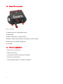
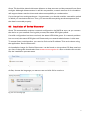
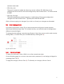
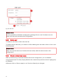
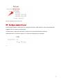
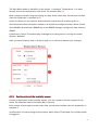
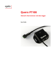
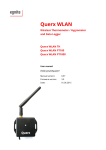
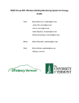
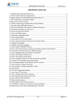
Querx TH
Web thermometer / hygrometer
User's manual
Querx TH is a networking enabled measuring device for
reliably monitoring temperature and humidity. Configuration
is carried out via web interface. Gathered values are internally
logged and graphically depicted over time. On exceeding
configurable thresholds, Querx TH triggers alarms and sends
notifications via email, SNMP trap and syslog. Cloud interfaces
provide world wide access to the collected data and easy
integration of Querx TH into own projects.
egnite cannot be held responsible for any technical or typographical errors and reserves the
right to make changes to the product and manual without prior notice.
egnite is not liable or responsible for any damage incurred in connection with the
furnishing, performance or use of this product.
Revision 1.7
© 2014 egnite GmbH, Germany. All rights reserved.
All trademarks are properties of their respective owners.
Latest information on our products is available on our websites www.egnite.de and
sensors.egnite.de.
Table of contents
1
Introduction
1.1
1.2
1.3
1.4
1
About Querx TH.......................................................................................... 1
Querx TH features....................................................................................... 1
Querx TH at a glance.................................................................................. 2
Fields of application ................................................................................... 2
2
Included in delivery (article EGN600114)
3
3
Putting into operation
4
3.1
3.2
3.3
3.4
3.5
4
Connect Querx TH....................................................................................... 4
Installation of 'Device Discoverer' ............................................................5
Automatic network configuration .............................................................9
Network configuration with 'Device Discoverer'.......................................9
A first look at the web interface...............................................................10
Required basic configuration
4.1
4.2
11
System settings......................................................................................... 11
Time settings............................................................................................. 12
Manually setting time and date ......................................................................12
Synchronizing via NTP.....................................................................................13
4.3
4.4
5
Set temperature unit................................................................................. 13
Reset recorded sensor data......................................................................14
Advanced basic configuration
5.1
15
Network settings....................................................................................... 15
Automatic configuration via DHCP ................................................................15
Manual configuration.......................................................................................15
DNS server ......................................................................................................16
Further settings................................................................................................16
5.2
User management ................................................................................... 17
Add or edit user................................................................................................17
Delete user........................................................................................................18
Disable anonymous access.............................................................................18
5.3
6
Configure session timeout........................................................................ 19
Configuration of alarm functions
6.1
20
Configuration of the sensors....................................................................20
Thresholds and hysteresis...............................................................................20
Configuration of the temperature sensor.......................................................20
Configuration of the humidity sensor.............................................................21
6.2
Configuration of alarm emails..................................................................22
Email accounts.................................................................................................23
Email recipients................................................................................................25
Global email settings.......................................................................................26
Templates for alarm emails.............................................................................27
6.3
SNMP traps............................................................................................... 28
Configuration....................................................................................................28
Receive traps with SNMP management software.........................................30
6.4
6.5
7
Configuration of syslog............................................................................31
Configuration of the status LED...............................................................32
Access on the measured data
7.1
33
Web interface............................................................................................ 33
Currently measured values.............................................................................33
Chronological sequence of values..................................................................33
7.2
Data export to cloud services...................................................................34
ThingSpeak integration...................................................................................34
Xively integration ............................................................................................35
8
Firmware updates
8.1
36
Availability of firmware updates..............................................................36
Installation of firmware images......................................................................36
Activation of firmware images........................................................................37
9
Troubleshooting
9.1
38
Possible errors........................................................................................... 38
No network connection....................................................................................38
Querx TH is slow..............................................................................................38
Querx TH has gaps in its chronology.............................................................38
After a firmware update, Querx TH doesn't work anymore..........................38
Lost log-in data.................................................................................................38
Network configuration unknown....................................................................38
9.2
Actions to perform.................................................................................... 39
Rebooting the device.......................................................................................39
Configuration reset..........................................................................................39
Activation of the alternative firmware buffer.................................................40
10
Appendix 1: Sensor specifications
41
10.1 Temperature sensor.................................................................................. 41
10.2 Humidity sensor........................................................................................ 42
11
Appendix 2: Specifications
43
12
Appendix 3: Manufacturer
45
1
Introduction
1.1 About Querx TH
Querx TH is powered with 5 V DC over a Micro-USB jack. The device can be connected to a
network over a 100 MBit Ethernet interface.
Querx TH monitors temperature and humidity in its surrounding and sends out alarms via
email, SNMP trap and syslog messages when configurable thresholds are exceeded.
Furthermore, the collected data can be exported to the cloud providers Xively and
ThingSpeak.
The advanced temperature range allows measurements between -40 °C and 85 °C (-40°F to
185 °F).
Querx sensors are water- and oil-repellent. Protected by a membrane, they are also dustproof from a particle size of 35 micro meters on and withstand a water pressure of 2.7 bars.
The sensors are calibrated by factory and specified by low deviations of ±2 % typical for the
humidity and ±0.3 K for the temperature sensor (see appendix 1, sensor data).
1.2 Querx TH features
• Reliable monitoring of temperature and humidity
• Integrated high-quality sensors: oil-repellent, water- and dustproof
• Alarms via email, SNMP trap and syslog
• StartTLS – supports Gmail, GMX etc.
• Easy configuration via web interface
• Clear graphical depiction of temperature and humidity gradiation
• Programming interfaces over cloud
• Data access via Android app
• Power supply over Micro-USB
• Battery backed real-time clock
• Advanced temperature range: -40 °C to 85 °C (-40 °F to 185 °F)
• Compact size: 56,3 mm x 40 mm x 21 mm (2.2 in x 1.6 in x 0.8 in) plus 340 mm (13.8 in)
sensor cable
1
1.3 Querx TH at a glance
Fig. 1.1: Overview
(1) Push button for configuration reset
(2) Status LED
(3) Micro-USB jack for voltage supply
(4) Sensor cable with sensors for temperature and humidity
(5) RJ-45 jack for network integration
(6) Link LED
1.4 Fields of application
• Server room monitoring
• Estate monitoring
• Automated climate profiling for buildings
• Preventive conservation
• Cause-determination for mould-remediation
2
2
Included in delivery (article EGN600114)
• Querx TH with sensors for temperature and humidity
• Ethernet cable
• Micro-USB cable
• USB wall plug adapter witch clippings for UK, EU, US and AU
• CD with software and documentation
3
3
Putting into operation
3.1 Connect Querx TH
Querx TH is shipped with a Micro-USB plug-in power supply which includes clippings for
usage in several countries. Choose the right clipping and push it into the guide rails from
above until it locks in place.
Fig. 3.1: Prepare adapter (Example: EU clipping)
Now connect the power supply to Querx TH, using the Micro-USB cable. If no free wall
outlet is available, you can instead connect Querx TH to a free USB port (1). The status LED
lights yellow. Querx TH needs 5 V voltage supply, consuming less than 1 W.
Now connect Querx TH to your network, using the provided Ethernet cable (2).
Fig. 3.2: Connect Querx TH
4
Querx TH should be placed with some distance to heat sources and be protected from direct
sunlight. Although measurements in still air are possible, a certain amount of air circulation
will support better reaction times and reduce susceptibility to condensation.
If you change from analogue thermo- / hygrometers, you should consider a transition period
in which you use both solutions. Thus, you ensure that everything works as expected and
the data is recorded properly.
3.2 Installation of 'Device Discoverer'
Querx TH automatically receives a network configuration via DHCP as soon, as you connect
the device to your network. During this process, the status LED lights yellow.
If a valid configuration has been received, the status LED blinks green. If a network problem
has occurred, the status LED lights red. Please ask your network administrator in this case.
To access Querx' web interface, you need to find out its IP address. This can be done using
the application 'Device Discoverer'.
An installation image for 'Device Discoverer' can be found on the product CD. New versions
can free of charge be downloaded from www.sensors.egnite.de. After a double click on this
file, the installation process starts.
Fig. 3.3: Execute installation image
At first, choose the language you want to use and click OK to continue.
Fig. 3.4: Choose language
5
The installer asks you to close other applications before proceeding. Afterward click on
Next.
Fig. 3.5: Close other applications
You are being asked to choose the components you want to install. Keep the suggested
selection and click on Next.
Fig. 3.6: Choose components to install
6
Please choose the folder into which you want to install 'Device Discoverer' and click on Next.
Fig. 3.7: Choose folder
Now choose a start menu folder for 'Device Discoverer'. Then, click on Install to install
'Device Discoverer' onto your system.
Fig. 3.8: Choose start menu folder
7
After the installation has finished, click on Next.
Fig. 3.9: Click next
Finally click on Finish to exit the installer.
Fig. 3.10: Finish installation
Now you can start 'Device Discoverer' from the windows start menu.
Fig. 3.11: Start 'Device Discoverer'
8
3.3 Automatic network configuration
'Device Discoverer' recognizes all Querx devices within your local network and lists them in
a table. The first column shows the system name. This name can be changed from the web
interface. The second column shows the IP address, over which Querx TH can be accessed.
If you double-click on the row with the device you want to configure, a browser window
opens and loads the web interface.
Fig. 3.12: 'Device Discoverer'
3.4 Network configuration with 'Device Discoverer'
If you don't have a DHCP server running in your network, you have to manually set an IP
address and a network mask. You can do this with 'Device Discoverer' or the Android app
'Querx Discoverer', which can be found in the Google PlayStore.
In Device Discoverer right-click on the device that you want do configure and choose Device
configuration. In the dialogue window, provide an IP address that is used to connect to
Querx TH and an IP mask for the definition of the subnet Querx is located in.
Finally, click on OK to apply your changes. Querx TH reboots with the new settings.
Fig. 3.13: Manual network configuration
To configure Querx TH to work with DHCP at this point, simply set IP address and IP mask to
0.0.0.0.
Further configuration is carried out via web interface.
9
3.5 A first look at the web interface
After you have entered Querx TH's IP address into your brower's address field or after you
have double-clicked on the entry in 'Device Discoverer', you see the front page. Here you
find currently measured values, as well as the depiction of their development over time.
Fig. 3.14: Web interface
The charts on the left side show the temperature and humidity gradations within the last
seven days. The upper chart shows temperature development, the lower one the
development of humidity. The red lines show the configured alarm thresholds.
The bars on the right side show currently measured values for temperature and humidity. If
they are green, the sensor is in the defined safe state. Red bars show an active alarm, one of
the thresholds is exceeded. A yellow color shows that the sensor measures values within
the hysteresis range (see 6.1, configuration of the sensors).
At the upper right part of the front page you can log in with a user name and a password.
This is needed if you have set up users and assigned them access right (see 5.2, user
management).
10
4
Required basic configuration
For proper operation, some basic configuration need to be carried out. Click at
Configuration in the upper right corner of the front page to access the configuration
backend.
On the left side of the screen, you find the configuration menu, from where you can navigate
through the different configuration areas. The center part of the page shows the
configuration options that you can set. On the right side, you find some explanatory
information on the different configuration options.
Fig. 4.1: Configuration backend
4.1 System settings
On the start page of the backend, which can also be accessed over the menu entry System /
General, you should provide a System name for your device. It is the name shown in 'Device
Discoverer'.
Furthermore it is used to identify the source of an alarm. This name can consist of up to 15
alphanumerical characters.
Click on Save to apply or on Cancel to discard your changes.
11
Fig. 4.2: Choose system name
4.2 Time settings
Click on System / Time to open the configuration page for date and time settings. These
settings allow Querx TH to put a time stamp to every measuring point, so the development
of data can be followed.
First set the UTC offset for the time zone that applies to your location. You can find an
overview at http://en.wikipedia.org/wiki/List_of_time_zones_by_UTC_offset.
Afterward click on Save to make your settings apply.
Fig. 4.3: Set UTC offset
4.2.1
Manually setting time and date
Enter the current date into the corresponding field. Please use the little-endian date format
with dots as separators. That is 01.01.2014 for the First of January, 2014. Now, enter the
current time with hours, minutes and seconds separated by colons. So for half past twelve
you would enter 12:30:00.
You can also pick up the current time from the computer you are working on. To do so, just
click on the button Sync-PC.
Finally click on Save to apply the changes.
12
Fig. 4.4: Set time
4.2.2
Synchronizing via NTP
Date and time can also be received via the Net Time Protocol. Insert a valid NTP server
address into to the corresponding field.
After you have clicked on Sync NTP, time and date are queried via network and saved in the
background. Do not click on Save afterward, as you would overwrite the received settings
with the values given in the input fields.
Fig. 4.5: Synchronization via NTP
Please notice:
If Querx TH is able to connect to the provided NTP server, its time settings are
automatically updated once an hour.
If no NTP server is given, Querx TH can save the provided values and keep track of the time
with the battery backed internal clock.
4.3 Set temperature unit
Open the page Sensors / Temperature to set the temperature unit you want to use. You can
choose between °Celsius, °Fahrenheit and Kelvin.
Click on Save to apply your changes.
13
Fig. 4.6: Set temperature unit
4.4 Reset recorded sensor data
To restart the recording of sensor data with the new configuration, you have to delete the
sensor data collected so far.
Open the page Maintenance / Reset and click the button reset right of Sensor data.
Fig. 4.7: Reset sensor data
On the following page, confirm that you want to delete the data by ticking the checkbox
right of Are you sure?. Finally click on the buttonYes.
Fig. 4.8: Confirm data deletion
14
5
Advanced basic configuration
After the configuration steps in the last chapter, Querx TH is ready-for-operation and records
the measured sensor data. To configure Querx TH for your specific use case, following
configuration options can be set.
5.1 Network settings
Querx TH automatically receives a network configuration via DHCP. You can also do the
network setup manually on the page System / Network, for example if you want to assign a
static IP.
5.1.1
Automatic configuration via DHCP
If you tick the DHCP checkbox, Querx TH gets an IP address, a network mask and a gateway
from the DHCP server.
Fig. 5.1: DHCP activation
5.1.2
Manual configuration
If you want to manually set up the networking options, you have to untick the DHCP
checkbox. In this case you have to provide the following parameters:
• Local IP address
Enter the IP address, over which Querx TH should be accessed though the network.
• Network mask
Enter a definition for the subnet, in which Querx TH is located.
• Gateway IP address
Enter the IP address of the gateway, which serves as default route to external networks.
15
Fig. 5.2: Manual network configuration
Please ask your network administrator if you don't have the needed values available.
5.1.3
DNS server
It is required to configure a DNS server, for example in order to send emails. If you have the
DHCP enabled, this value is automatically provided in most cases. Check if the field holds a
valid value and change it, if needed.
Fig. 5.3: DNS server
5.1.4
Further settings
Following advanced options can be configured:
• Syslog server
If you provide a syslog server, Querx TH sends alarms, general information and error
messages via syslog protocol.
• HTTP port
Here you can configure on which port the web interface of Querx TH can be accessed. The
16
standard value is 80.
• Discovery port
This port is needed to enable the discovery service of Querx TH. With this service
enabled, the device can be found and configured by 'Device Discoverer'. The value should
be 9806.
• Discovery IP mask
This value specifies the network segment, in which Querx TH accepts configuration
changes from 'Device Discoverer'. Typically this is 255.255.255.255.
Click on Save to apply your changes. If you click on Cancel, your changes are discarded.
5.2 User management
In its basic configuration, Querx TH can be accessed and configured via web interface
without providing any login data. To increase security, you can add users and assign them
different access privileges.
To change the user settings, open the page System / User. Here you can add or edit users by
clicking Edit (1). If users exist, you can delete them by clicking Del (2).
Fig. 5.4: System users
5.2.1
Add or edit user
To add or to edit a user, click on Edit in one of the unused user slots.
On the following page you can set a user name and a password (1) and assign privileges for
accessing Querx TH (2).
To apply the changes, click on Save (3). To discard your changes, click on Cancel.
17
Fig. 5.5: Edit user
Please notice:
It is only possible to withdraw configuration privileges from a user if at least one user
exists, who has write access to the configuration.
5.2.2
Delete user
To delete a user click on Del in the user list.
To finally remove that user, you need to confirm deleting the user with a click on Yes on the
following page.
Please notice:
Users can only be removed, if at least one user exists, who has write access to the
configuration.
5.2.3
Disable anonymous access
After you have set up a user with write access to the configuration, you can disable
anonymous access. For that, simply edit the user named Anonymous and set its right group
to Disabled.
Afterward, click on Save to apply or on Cancel to discard your changes.
18
Fig. 5.6: Disable anonymous access
5.3 Configure session timeout
On the page System / User you can configure the time, after which a user is automatically
logged out if no action is performed.
In the section Login enter the time in seconds into the field Session timeout.
Afterward click on Save to apply or on Cancel to discard your changes.
Fig. 5.7: Session Timeout
19
6
Configuration of alarm functions
Setting up alarms is divided into two steps:
In the first step, you have to configure the sensors to trigger alarms if certain thresholds are
exceeded.
In the second step you have to configure how Querx TH will react on those alarms.
Possible actions are sending emails and SNMP traps. Furthermore, syslog messages are
sent, if a syslog server is provided.
6.1 Configuration of the sensors
Querx TH comes with integrated sensors for temperature and humidity, which can
independently be configured.
6.1.1
Thresholds and hysteresis
Each sensor can be assigned an upper and a lower limit, between which Querx TH is in the
normal state. If these limits are exceeded, Querx TH triggers an alarm.
Do avoid multiple alarms, you can set a value for hysteresis. This is the amount of units,
which the measured values have to move back in the direction of the normal state, before
another alarm is triggered.
Please look at the following image:
Fig. 6.1: Hysteresis
In this example, the temperature sensor is set to a lower limit of 15 °C and an upper limit of
55 °C. Hysteresis is set to 10.
If an alarm is triggered at 55 °C the sensor has to measure 45 °C or less in order to trigger
another alarm on exceeding 55 °C.
6.1.2
Configuration of the temperature sensor
On the page Sensors / Temperature you set up the alarm function for the temperature
sensor.
20
The field Name takes an identifier for the sensor, in example 'Temperature'. You have
already chosen the temperature unit Querx TH operates with. (1)
Now configure the safe range by setting an upper and a lower limit, as well as a sensible
value for hysteresis, in example 2 (2).
Under On alarm you can choose, what actions are performed if an alarm goes on.
Send email will send information emails to all recipients configured under Alarm / Email.
Send SNMP trap will send a SNMP trap to the SNMP manager configured under Alarms /
SNMP.
Furthermore, Querx TH sends syslog messages to a syslog server if configured under
System / Network.
After you have finished, click on Save to apply or on Cancel to discard your changes.
Fig. 6.2: Configure temperature sensor
6.1.3
Configuration of the humidity sensor
For the configuration of the humidity sensor, you don't need to provide a physical unit.
Querx TH measures relative humidity (RH) in percent.
Enter values for the upper and the lower limit, as well as a sensible value for hysteresis, in
example 5.
In the section On alarm configure the actions, which Querx TH will take if a humidity alarm
is triggered.
21
Send email will send alarm emails to all recipients configured on the page Alarm / Email.
Send SMTP Trap will send SMTP traps to the SMTP manager specified under Alarm / SMTP.
If you have configured a Syslog server on the page System / Network, Querx TH will send
also syslog messages.
When you have finished, click on Save to apply or on Cancel to discard you changes.
Fig. 6.3: Configure humidity sensor
6.2 Configuration of alarm emails
Open the page Alarm / Email to configure up to 4 recipients, that will be notified through up
to two email accounts.
In the first section, you see a list of the email accounts, which are used to send alarm emails
(1). The central section lists the email addresses, to which the alarm emails are sent (2).
In the bottom section you can enter the messages that are sent with an alarm, and configure
some basic email settings (3).
22
Fig. 6.4: E-Mail configuration
6.2.1
Email accounts
To enable alarm emails you have to configure an account, which is used for sending. In case
that the server, to which the account belongs, is not available, you can provide a second
account as backup.
If none of the configured mail servers is responding, for example in case of network failure,
Querx TH records the last 16 events that have occurred and sends the emails as soon as the
connection could be established again.
To configure a mail server, open the page Alarm / Email. In the section Email accounts you
see two slots, where email accounts can be added. Click on edit to create an account.
Fig. 6.5: Create email account
23
On the next page enter the host name of the SMTP server and a port number.
• Host name
Please enter the host name of your SMTP server.
• Port
Please enter the port number for your SMTP server. In most cases this is 587.
Nowadays you will hardly find a mail server that allows you to send emails without
authentication. Please tick the Authentification checkbox and enter a user name and a
password (2).
Click on Save to apply or on Cancel to discard you changes.
If you click on Test, Querx TH tries to connect to the mail server. If you didn't provide valid
data, the corresponding fields turn red. f the attempt was successful, the Test button turns
green.
Please notice that not all mail servers are configured to return error messages. So please
ensure correct operation by sending a test email (see 6.2.2, email recipients).
Fig. 6.6: Configuration of email accounts
Please notice:
The login data is stored on QuerxTH without encryption. It is thus a good idea not to use an
existing email account but set up a dedicated account for the device. Your system
administrator can support you.
Edit email account
To edit an email account, open the page Alarm / Email and click on Edit left of the account
that you want to change.
24
Delete email account
To delete an email account, open the page Alarm / Email and click on Del left of the account
that you want to remove.
Fig. 6.7: Delete email account
On the following page you have to confirm that you want to delete the account. If you click
on No, the account will remain unchanged. If you click on Yes, the account will be deleted.
Fig. 6.8: Confirm deleting of the mail account
6.2.2
Email recipients
Querx TH is now able to send alarms via email. Now you have to provide recipients to be
informed on occurring alarms.
To create recipients open the page Alarm / Email. In the section Recipients, you find four
slots into which recipients can be entered. To do so, click on Edit in one of the lines.
Fig. 6.9: Create email recipient
On the next page, enter a valid email address in the field Email (1). Afterward, choose the
mail account where emails should be send from per default (2).
With a click on the button Test, an email is sent. If everything works well, click on Save to
apply your changes. If you click on Cancel your changes will be discarded.
25
Fig. 6.10: Enter recipient
Edit email recipient
To edit an existing email recipient, open the page Alarm / Email and click on Edit.
Delete email recipient
Open the page Alarm / Email and click on Del in the line with the email recipient that you
want to remove.
Fig. 6.11: Delete recipient
On the next page, confirm deleting the recipient by clicking Yes. If you click No, the recipient
remains unchanged.
Fig. 6.12: Confirm deleting the recipient
6.2.3
Global email settings
Open the page Alarm / Email. In the section Email settings click on Edit left of Global
Settings.
26
Fig. 6.13: Global email settings
On the next page you can set the address, where emails are sent from and a text, that is
added to all system emails.
• Sender address
Please enter a valid email adress
• Email text
Please enter a text template that is going to be added to all system mails. Within this text
you can use some functional characters: \t creates a tabulator and \n creates a line break.
Fig. 6.14: Global email settings
6.2.4
Templates for alarm emails
Open the page Alarm / Email. In the section Email settings you can edit the email templates
for temperature- and humidity alarms. Click on Edit left of the alarm which you want to
configure.
Fig. 6.15: Edit alarm email templates
27
Within the Alarm section, you can enter the email templates that are processed if an alarm
occurs.
The section Back to normal holds the email templates to be processed when an alarm stops.
Fig. 6.16: Edit alarm email templates
You can add some variables and functional characters to your templates. Those are
dynamically replaced when an email is sent:
Variable
$S
$V
$U
\t
\n
Value
Name of the sensor that has triggered the alarm
Measured value of the sensor
Physical unit of the measured value
Line break
Tabulator
After you have adjusted your email templates, click on Save to apply or on Cancel to discard
your changes.
6.3 SNMP traps
With the Simple Network Management Protocol you can easily set up a monitoring system
for your networking infrastructure. Querx TH can send SNMP traps to notify an SNMP
manager on triggered and stopped alarms.
6.3.1
Configuration
Open the page Alarm / SNMP. Here you can provide the details for the traps that are sent if a
temperature or humidity alarm occurs or the sensor returns back to normal.
28
At first, enter your SNMP manager and the specific trap codes for the different status
changes.
• SNMP manager
Enter the IP address of the SNMP manager that should monitor Querx TH.
• Alarm trap
Enter the specific trap code for off-going alarms.
• Normal trap
Enter the specific trap code for stopped alarms.
Fig. 6.17: Basic SNMP settings
Now configure the SNMP parameters for the temperature (1) and the humidity (2) sensors.
• Object identifier
Enter an OID for the sensor.
• Alarm value
Enter a value that is sent with the trap for off-going alarms.
• Normal value
Enter a value that is sent with the trap for stopped alarms.
29
Fig. 6.18: Configure SNMP traps
When entering values to be sent with a trap, you can make use of some variables, which are
automatically replaced on transmission.
Variable
$S
$V
$U
Value
Name of the sensor
Measured value
Physical unit of the measured value
Click on Save to apply or on Cancel to discard your changes.
6.3.2
Receive traps with SNMP management software
SNMP traps sent by Querx TH can be received with any SNMP enabled software like Nagios,
Tivoli or OpenView.
The MIB-Browser by iREASON contains a tool called Trap Receiver, with which you can test
the SNMP trap function.
In the upper area of the application window you see a list with received SNMP traps, the
lower area shows detailed information on the selected trap. Among other information you
can see:
(1) the specific trap code for the alarm
(2) the OID of the sensor that has triggered the alarm
(3) the alarm value that was sent with the trap
MIB browser and trap-receiver can be downloaded from http://ireasoning.com/.
30
Fig. 6.19: SNMP traps in Trap Receiver
6.4 Configuration of syslog
To sent alarms and information through syslog, you have to provide a syslog server on the
page System / Network (see 4.1, Network configuration).
Through syslog, Querx TH sends out a multitude of information and warnings. You can
configure your syslog server on how to deal with this information, in example what should
be logged or used in other ways.
The following image shows some of the syslog output produced by Querx TH in the free
syslog server from IPSWITCH. The software can be downloaded from www.ipswitch.com.
Fig. 6.20: Syslog messages from Quern TH
31
6.5 Configuration of the status LED
Open the page Alarm / Status LED to configure the optical output for the normal state (1), as
well as for temperature or humidity alarms (2).
• Blink rate
Here you configure the rate in which the LED blinks green in normal state.
• Temperature
Here you configure the LED color for temperature alarms.
• Humidity
Here you configure the LED color for humidity alarms.
Click on Save to apply or on Cancel to discard your changes.
Fig. 6.21: Configure the status LED
32
7
Access on the measured data
Querx TH offers several interfaces to receive currently measured and recorded data:
• Visual depiction via web interfaces
• Data export to Xively
• Data export to ThingSpeak
• Android App 'Querx Discoverer' with direct data access through LAN or remote access
through clouds.
7.1 Web interface
Fig. 7.1: Web interface
7.1.1
Currently measured values
On the right side of the screen, you see the currently measured values of both sensors. If the
bars are green, Querx TH is in the normal status. If one of the bars is red, the particular
sensor is in alarm mode. A yellow bar shows that the sensor is measuring values that are
within the hysteresis range.
7.1.2
Chronological sequence of values
On the left side of the web interface you see the development of temperature and humidity
within the last seven days. The upper diagram shows the temperature chart, the lower one
shows the humidity chart. The red lines depict the configured the alarm thresholds.
33
7.2 Data export to cloud services
The data collected by Querx TH can be exported to cloud services. This allows you to merge
data collected from several devices to set up a central monitoring site for different facilities.
Also it is possible to set up world wide data access for different users or for own monitoring
applications using the provided APIs.
Fig. 7.2: Measured data at ThingSpeak
7.2.1
ThingSpeak integration
To use Querx TH with ThingSpeak, open the page System / Cloud. Here you have to fill in
the following fields:
• API key
Enter the API key that allows you to write on a ThingSpeak channel.
• Temperature field ID
Enter the number of the field which is used for temperature values.
• Humidity field ID
Enter the number of the field which is used for humidity values.
Click on Save to apply or on Cancel to discard your changes.
Fig. 7.3: Configure ThingSpeak
Please notice, that QuerX TH does not encrypt your API key on the device.
34
More information on how to set up a ThingSpeak channel or how to integrate channel data
into your website or intranet can be found on www.thingspeak.com.
7.2.2
Xively integration
Querx TH can also update Xively feeds. The channels to be updated correspond to the
names, that you have assigned to the sensors (see 6.1, configuration of the sensors)
To configure Querx TH for Xively, open the page System / Cloud and fill in the following
fields:
• API key
Enter the API key with which you can write on your Xively feed.
• Feed ID
Enter the ID of the feed that you want to write on.
Click on Save to apply or on Cancel to discard your changes.
Fig. 7.4: Configure Xively
Please note that Querx TH does not encrypt the API key.
More information on how to set up and access a Xively feed can be found on
www.xively.com.
35
8
Firmware updates
To extend Querx TH's scope of operation, egnite frequently provides new firmware versions.
These can easily be uploaded onto and activated on the device.
8.1 Availability of firmware updates
To figure out what firmware version you are currently using, open the page System /
General. In the section Version you can find the firmware version just beside of the label
Firmware.
Fig. 8.1: Find out firmware version
The most recent firmware image can be downloaded from www.sensors.egnite.de. If the
version of the provided download is higher than the version you are running on Querx TH, a
firmware update might be sensible.
Right-click on the download link and choose Save link as from the pop-up menu and choose
a location where to save the file.
Fig. 8.2: Save firmware image
8.1.1
Installation of firmware images
To install a new firmware version, open the page Maintenance / Firmware.
Now choose a buffer into which you want to install the image (1). This should be either the
slot with the lowest firmware number or an empty slot.
Now select the file that you have just downloaded (2). Then, click on Upload to save the
firmware on the device (3). The upload may need some time. After it is finished, the new
firmware version is shown next to the buffer that you chose earlier.
36
Fig. 8.3: Upload firmware to Querx TH
8.1.2
Activation of firmware images
After uploading a new firmware image, you have to activate it. Open the page Maintenance /
Firmware. In the section Activation you see the two firmware buffers.
Fig. 8.4: Activate firmware image
Select the one with the version that you want to run (1) and click on Activate (2). The
software is now written into the internal memory.
Once the writing has finished, Querx TH reboots. During this process, the LED turns yellow.
After successfully booting, the LED turns back to normal.
Please note:
The activation process can take a couple of seconds. Do not cut Querx TH off from the
power supply during this time, as the device can be damaged.
If, for some reason, the firmware update failed and the device refuses to take up normal
operation, you can manually reactivate the other firmware buffer (see 9.2, actions to
perform).
37
9
Troubleshooting
9.1 Possible errors
9.1.1
No network connection
If you are not able to connect to Querx TH, you probably need to manually configure
network settings. Start the application 'Device Discoverer'. If the device is not listed here,
check if it is properly connected to the network. If that is the case, a network problem may
have occurred. Please ask you network administrator.
If Querx TH is shown in the list, please continue as described in sections 3.3 and 3.4
9.1.2
Querx TH is slow
In the web interface, open the page System / General and check the value for Memory
Usage. If this value is greater than 70 %, it is likely that you have to many network
connections opened. Check if you can close browser windows connected to the web
interface.
9.1.3
Querx TH has gaps in its chronology
In the web interface, open the page System / General and check the value for Uptime. Here
you can see the time that Querx TH was running from the last boot on. Please ensure that
the power supply was not accidentally interrupted.
9.1.4
After a firmware update, Querx TH doesn't work anymore
If after a firmware update Querx TH refuses operation, you can reactivate the other firmware
buffer on the device (see 9.2, actions to perform).
9.1.5
Lost log-in data
If you don't remember the log-in data for Querx TH, you can reset the device configuration
(see 9.2, actions to perform).
9.1.6
Network configuration unknown
If you don't remember the network configuration for Querx TH, you can use the utility
'Device Discoverer' to locate Querx TH in your network.
If Querx TH was configured for a network, which you have no access to, you can manually
reset the configuration (see 9.2, actions to perform).
38
9.2 Actions to perform
9.2.1
Rebooting the device
There are two ways to restart Querx TH:
Warm start via web interface
In the web interface open the page Maintenance / Reset. Click on Reset next to System
restart. Confirm rebooting the device by clicking Yes on the next page.
Cold start through power disconnect
Remove the Micro-USB cable from Querx TH to interrupt power supply. Wait for a couple of
seconds before you reconnect the device.
9.2.2
Configuration reset
There are two ways to reset the device:
Configuration reset via web interface
Open the page Maintenance / Reset in the web interface. Click on “Reset” next to
“Configuration”. Confirm the configuration reset by clicking Yes on the following page.
Hardware reset
If you can't configure Querx TH anymore, for example if you have lost your log-in data, you
can perform a hardware reset.
Left of the status LED you find a little opening. Underneath is the button for resetting the
configuration. Push it with a ball-pen. Do not use a pencil, as the pencil lead could break and
damage the device.
The status LED starts blinking red. Hold the button pushed until the blinking stops to reset
the configuration. If you release the button while Querx TH is blinking, the old configuration
is kept.
39
Fig. 9.1: Hardware reset of the configuration
9.2.3
Activation of the alternative firmware buffer
If after a firmware update problems occurred, you can change the firmware image to be
executed, given that there is an alternative firmware version on the device (see 8, Firmware
updates).
Remove Querx TH from the power supply. Now take a ball-pen and push the button
underneath the opening left of the status LED. Don't use a pencil, as the pencil lead could
break and damage the device. Keeping the button pushed, reconnect the power supply.
The status LED starts to blink red. You can interrupt the activation process here if you
release the button. If you keep it pressed, after a few seconds the LED will light red without
blinking. If you now release the button, the other firmware image is written into Querx TH's
internal memory and the device will be restarted.
Fig. 9.2: Change active Firmware image
40
10 Appendix 1: Sensor specifications
10.1 Temperature sensor
Deviation
Long term stability
Measurement Typical
range
-10 °C – 85 °C ± 0.3
-40 °C – 100 °C See image
≤ 0.01 °C
Maximal
Unit
± 0.4
°C
°C
°C / year
41
10.2 Humidity sensor
Deviation
Measurement range
0 % – 80 %
80 % – 100 %
Long term stability
Typical
±2
See image
≤ 0.25
Maximal
±3
Unit
%
%
% / year
Error of measurement after exposure to extreme circumstances
If the sensors are exposed to extreme environmental circumstances like very high
temperature, drought or moistness, the sensing film can get to dry or to wet. This leads to a
temporary decrease of accuracy for the humidity senor.
Recalibration of sensors
The sensors are calibrated by factory and do not need to be manually recalibrated.
Recalibration can be carried out by egnite.
42
11 Appendix 2: Specifications
Measuring range temperature
40 °C to 85 °C
-40 °F to 185 °F
Accuracy temperature
±0.3 °C from -10 °C to 85 °C / ±1.0 °C from -40 °C to -10 °C
±0.5 °F from 14 °F to 185 °F / ±1.8 °F from -40 °F to 14 °F
Resolution temperature
0.1 °C
0.2 °F
Measuring range humidity
0 % bis 95 % RH
Accuracy humidity
±2 % RH from 0 % to 80 % RH at 30 °C (86 °F)
±4,0 % RH from 80 % to 95 % RH at 30 °C (86 °F)
Resolution humidity
1 % RH
Humidity sensor
CMOS IC with polymide film
Callibration
By factory
Sensor heating
Integrated
Ethernet
10/100 Mbit RJ45, HP Auto-MDIX
Static or dynamic (DHCP client) IP
System
Nut/OS 5
Firmware updates
Over web interface, rescue function
Data capacity
At least 51 days internal
Protocols
HTTP, SMTP, DHCP, SNTP, Syslog, SNMP (Traps only) ,
Nut/Discovery
Webinterface
Password protection, Diagram, Live Update, HTML5,
CSS3, JSON and SVG,
User Management (3 Users / 3 Groups)
E-Mail
Up to 4 Recipients over 2 SMTP servers
SNMP
Traps
Status LED
Red, green, yellow
Date / Time
Battery backed real-time clock with SNTP update
Power supply
5 V DC ... 5.5 V DC
Consumption
Typical 120 mA 0.6 W / maximal 200 mA 1 W
Operating conditions
-40 °C bis 85 °C, max. 95 % RH
-40 °F bis 185 °F, max. 95 % RH
Storage conditions
-40 °C bis 85 °C, max. 95 % RH
-40 °F bis 185 °F, max. 95 % RH
43
Housing material
ABS thermoplastic
Housing color
Black RAL 9011
Housing dimensions
56.3 mm x 40 mm x 21 mm plus sensing cable
2.2 in x 1.6 in x 0.8 in plus sensing cable
Length sensing cable
340 mm
13.8 in
Weight
35 g
0.07 lb
Connector
RJ45 (Ethernet), Micro-USB
Mounting
Wall mounting
Conformity
CE compliant
UL, USA / Kanada
UL94
Protection marking
IP20
RoHS compliance
EU Directive 2002/95/EC
44
12 Appendix 3: Manufacturer
egnite GmbH
Erinstrasse 9
44575 Castrop-Rauxel
Germany
Email: [email protected]
Tel.: +49 (0)2305 441256
Fax: +49 (0)2305 441487
www.egnite.de
sensors.egnite.de
45