1
Personal Computer Family
Service Information Manual
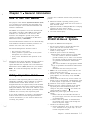
Preface
The purpose of this Service Information Manual (SIM) is to provide its user with the most frequently used
service-related maintenance and reference information.
The SIM is not required to service the Personal Computer family of products. The SIM has been made available as a convenience to the user.
The SIM is divided into sections by product-specific information for each machine type with additional
sections for general Personal Computer information.
This document can also be ordered by specifying Bill of Forms (BOF) 2481. Other items included in this BOF
are diskettes, service summary cards, tabs, binders, and plastic diskette holders. Individual form numbers for
these additional items are:
Diskettes
IBM Advanced Diagnostic for the 5150, 5155, and 5160, Version 2.25
IBM Advanced Diagnostic for the 5162 and 5170, Version 2.07
SA380033
SA38-0034
Service Summary Cards
5162 and 5170 Service Summary Card
5150, 5155, and 5160 Service Summary Card
SA38-0035
SA38-0036
Printer Supplement
Tabs
Plastic Diskette Holders 5.25Inch (2 U/M)
SA38-0040
SA38-0038
SA38-0015
First Edition (January 1989)
This major revision obsoletes SR28-0280-02.
The drawings and specifications contained herein shall not be reproduced in whole or in part without written
permission.
IBM has prepared this Service Information Manual for the use of IBM customer engineers in the installation,
maintenance, or repair of the specific machines indicated. IBM makes no representations that it is suitable
for any other purpose.
This publication could include technical inaccuracies or typographical errors. Changes are periodically made
to the information herein; these changes will be incorporated in new editions of the publication. IBM may
make improvements and/or changes in the product(s) and/or the program(s) described in this publication at
any time,
Requests for copies of IBM publications should be made to your IBM representative or to the IBM branch
office servicing your locality.
Address comments concerning the content of this publication to IBM Corporation, Dept. 90A, Bldg. 234-2,
Internal Zip 4307, 951 NW 51st St., Boca Raton, Florida, U.S.A. 33432. IBM may use or distribute whatever
information you supply in any way it believes appropriate without incurring any obligation to you.
References in this publication to IBM products, programs, or services do not imply that IBM intends to make
these available in all countries in which IBM operates.
0 Copyright International Business Machines Corporation 1989
* INSTRUCTIONS *
~
.bl
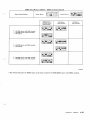
The PersonaI Computer Family Service Information Manual should be assembled in the following manner:
l
I
Tabs should be inserted at the beginning of each appropriate chapter.
-
The plastic Summary Card Holder (located at the back of the tabs) should be inserted in Chapter 21,
“Service Summary Cards.”
- The Service Summary Cards should be inserted into the plastic Summary Card Holder.
l
Plastic Diskette Holders should be inserted in Chapter 20, “Advanced Diagnostic Diskettes.”
- The Advanced Diagnostic Diskettes should be inserted in the plastic Diskette Holders.
The assembled manual should then be placed in the three-ring binder provided with this package.
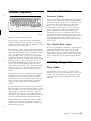
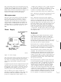
Safety
The following information has been included in this
publication for the use and safety of IBM personnel.
General Safety during Work
Use these rules to ensure general safety:
Observe good housekeeping in the area of the
machines during maintenance and after completing
it.
Use only field-supply items (such as adhesives,
cleaning fluids, lubricants, paints, and solvents)
that have been approved by IBM, that is, are supplied under an IBM part number.
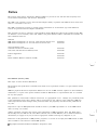
When lifting any heavy object:
1. Ensure that you can stand safely without slipping.
2. Balance the weight of the object between your
two feet.
3. Use a slow lifting force. Never move suddenly
or twist when you attempt to lift.
I
L-J
4. Lift by standing or by pushing up with your
leg muscles; this action removes the strain
from the muscles in your back. Do not attempt
to lift any objects that you think are too heavy
for you.
Wear safety glasses when you are:
-
Using a hammer to drive pins or similar parts
-
Drilling with a power hand-drill
-
Using spring hooks or attaching springs
- Soldering parts
-
Cutting wire or removing steel bands
-
Cleaning parts with solvents, chemicals, or
cleaning fluids
-
Working in any other conditions that might be
hazardous to your eyes.
Before you start the machine, ensure that other
service representatives and the customer’s personnel are not in a hazardous position
After maintenance, reinstall all safety devices
such as shields, guards, labels, and ground wires.
Exchange any safety device that is worn or defective for a new one.
Remember: Safety devices protect personnel
from hazards. You destroy the purpose of the
devices if you do not reinstall them before completing your service call.
Reinstall all covers correctly before returning the
machine to the customer.
Do not perform any action that causes hazards to
the customer or that makes the equipment unsafe.
Safety with Electricity
Put removed covers and other parts in a safe place,
away from all personnel, while you are servicing
the machine.
Observe these additional rules when working on equipment powered by electricity:
Always keep your tool case away from walk areas
so that other persons will not trip over it; for
example, put it under a desk or table.
. Do not wear loose clothing that can be trapped in
the moving parts of a machine. Ensure that your
sleeves are fastened or are rolled up above the
elbows. If your hair is long, fasten it.
Find the room emergency power-off (EPO) switch
or disconnecting switch. If an electrical accident
occurs, you can then operate the switch quickly.
Do not work alone under hazardous conditions or
near equipment that has hazardous voltages.
Always inform your manager of any possible
problem or if you must work alone.
Do not wear jewelry, chains, metal-frame
eyeglasses, or metal fasteners for your clothing.
Remember: A metal object lets more current
flow if you touch a live conductor.
. Insert the ends of your necktie or scarf inside
A-l
other clothing or fasten the necktie with a clip,
preferably nonconductive, approximately 8 cm (3
in) from the ends.
Safety
iii
l
l
- CAUTION:
Many customers have, near their equipment, rubber floor mats that contain small
conductive fibers to decrease electrostatic
discharges. Do not use this wrong type of
mat to protect yourself from electric
shock.
Disconnect all power:
-
Before removing or installing main units
-
Before working near power supplies
-
Before doing a mechanical inspection of power
supplies
-
Before installing changes in machine circuits.
Stand on suitable rubber mats (obtained
locally, if necessary) to insulate you from
grounds such as metal floor strips and
machine frames.
Before you start to work on the machine, unplug
the machine’s power cable, If you cannot unplug
the cable easily, ask the customer to switch off the
wall box switch that supplies power to the
machine, and either:
-
Lock the wall box switch in the off position, or
-
Attach a DO NOT OPERATE tag, Z229-0237,
to the wall box switch.
Observe the special safety precautions when you
work with very high voltages; these instructions
are given in IBM safety service memorandums
(SMs) and the safety sections of maintenance
information. Use extreme care when measuring
high voltages.
Note: A non-IBM attachment to an IBM machine
can be powered possibly from another source and
controlled by a different disconnecting switch or
circuit breaker. If you determine that this condition is present, ensure that you remove (eliminate)
this hazard before you start work.
.
Do not use worn or broken tools and testers.
Ensure that electrical hand tools, such as power
drills and Wire-Wrap1 tools, are inspected regularly.
Never assume that power has been disconnected
from a circuit. First, check that it has been
switched off.
If you need to work on a machine that has exposed
electrical circuits, observe the following
precautions:
-
Always look carefully for possible hazards in your
work area. Examples of these hazards are moist
floors, nongrounded power extension cables, power
surges, and missing safety grounds.
Ensure that another person, who is familiar
with the power-off controls, is near you.
Remember: Another person must be there to
switch off the power, if necessary.
Do not touch live electrical circuits with the glass
surface of a plastic dental mirror. The surface is
conductive; such touching can cause personal
injury and machine damage.
- CAUTION:
Some hand tools have handles covered
with a soft material that does not insulate
you when working with live electrical circuits.
Unless the maintenance information specifically
lets you, do not service the following parts with
power on them when they are removed from their
normal operating places in a machine:
Use only those tools and testers that are suitable for the job you are doing.
-
Remember: There must be a complete
circuit to cause electrical shock. By observing
the above rule, you may prevent a current
from passing through the vital parts of your
body.
-
When using testers, set the controls correctly
and use the IBM-approved probe leads and
accessories intended for that tester.
1 Trademark of the Gardner-Denver Co.
iv
Power supply units
Pumps
Blowers and fans
Motor generators
Use only one hand when working with
powered-on electrical equipment; keep the
other hand in your pocket or behind your
back.
and similar units. (This rule ensures correct
grounding of the units.)
.
If an electrical accident occurs:
-
Use caution; do not become a victim yourself.
- Switch off power.
!L_/
“L./j
-
Send another person to get medical aid.
-
If the victim is not breathing, decide
whether to give rescue breathing.
These actions are described below.
Emergency First Aid
When giving rescue breathing after an electrical
accident:
l
Use Caution. If the victim is still in contact with
the electrical-current source, remove the power; to
do this, you may need to use the room emergency
power-off (EPO) switch or disconnecting switch.
If you cannot find the switch, use a dry wooden
rod or some other nonconductive object to pull or
push the victim away from contact with the
electrical-current source.
l
Work Quickly. If the victim is unconscious, he or
she possibly needs rescue breathing. If the heart
has stopped beating, the victim may also need
external cardiac compression,
Only a trained and certified person2 should
perform external cardiac compressions.
l
Get Medical Aid. Call a rescue group, an ambulance, or a hospital immediately.
2. Look, listen, and feel to determine if the victim is
breathing freely:
a. Put your cheek near the victim’s mouth and
nose.
b. Listen and feel for the breathing-out of air. At
the same time, look at the victim’s chest and
upper abdomen to see if they move up and
down.
If the victim is not breathing correctly and you
decide that you want to give rescue breathing:
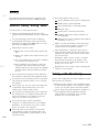
3, Continue to press on the victim’s forehead with
your hand and pinch together the victim’s
nostrils fl with the thumb and finger.
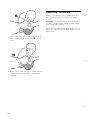
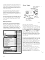
Rescue Breathing
Procedures
Determine if the victim needs rescue breathing:
1. Prepare the victim:
a. Ensure that the victim’s airway is open and
not obstructed. Check the mouth for objects
(such as chewing gum, food, dentures, or the
tongue) that can obstruct the flow of air.
b. Place the victim on his or her back, then put
one hand under the victim’s neck and the
other hand on the victim’s forehead.
q
c. Lift the neck with one hand
and press the
forehead backward with the other hand.
4. CAUTION:
Use extreme care when giving rescue
breathing to a victim who possibly has
breathed-in toxic fumes. Do not breathe-in air
that the victim has breathed-out.
Open your mouth wide and take a deep breath.
Make a tight seal with your mouth3 around the
victim’s mouthm and blow into it.
i
l2 If you want to be trained in giving this aid, ask a suitable organization (such as the Red Cross) in your area.
3 A rescue-breathing face covering (mask) or similar unit can be used if you have been taught how to use it.
Safety V
Reporting Accidents
Report to your manager or to your IBM site all accidents, possible hazards, and accidents that nearly
occurred.
Remember: An accident that nearly occurred can be
caused by a design problem. Quick reporting ensures
quick solving of the problem.
Report also each small electric shock, because the conditions that caused it need only differ slightly to cause
serious injury.
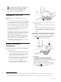
5. Remove your mouth and let the victim breathe out
while you check that the victim’s chest
moves
down.
q
6. Repeat steps 4 and 5 once every 5 seconds until the
victim breathes normally again or until medical
aid comes.
Vi
I
L-..J
Contents
Chapter 1. General Information
l-l
How to Use This Manual
l-1
l-l
Safety Inspection Guide
IBM Personal Computer, 5150/5160-Based
Systems l-l
Diskette Description
l-2
Media/Drive Compatibility Table
l-3
Diskette Care
l-4
Handling Static-Sensitive Devices
l-4
General Information 9-5
9-6
General Diagnostic Tips
9-8
Power Diagnostic Tips
9-9
System/Memory Diagnostic Tips
Diskette Drive/Fixed Disk Drive Diagnostic
9-14
Tips
9-23
5170 PC AT Switch Settings
9-26
5170 AT/370
9-28
Personal Computer AT Store Controller
2-l
Chapter 2. 4860 PCjr
System Board 2-2
Power Supply
2-2
Cordless Keyboard
2-3
2-3
General Information
4860 PCjr Diagnostics
2-3
General Diagnostic Tips
2-4
Power Diagnostic Tips
2-7
10-l
Chapter 10, 3270 PC Products
System Units
10-l
10-l
3270 PC
10-2
3270 Personal Computer AT
Diagnostic Tips and Information on the 3270 PC and
the 3270 PC AT
10-3
10-4
3270 PC/G
10-6
3270 PC/GX
5279 Color Display and 5278 Display Attachment
10-8
Unit
5379 Displays and 5378 Display Attachment
Units
10-9
10-10
5277 Mouse and 5083 Tablet Model 002
10-11
3270 Unique Error Codes
Diagnostic Tips and Information on PC/G, PC/GX,
AT/G, and AT/GX
10-12
Memory Option Switches
10-13
3270 Personal Computer G and GX (AT-Based Only)
10-14
Extended Memory Adapter
Chapter 3. 5140 PC Convertible
System Information
3-l
Power Sources 3-l
Options
3-2
3-l
Chapter 4. 5150 PC
4-1
5150/5160-Based System Diagnostics
4-3
General Diagnostic Tips
4-3
Power Diagnostic Tips
4-3
System/Memory Diagnostic Tips
4-4
Diskette Drive/Fixed Disk Drive Diagnostic Tips
Communications Diagnostic Tips
4-13
5150/5160-Based System Diagnostic Information
5150 PC Switch Settings
4-14
Chapter 5. 5155 P o r t a b l e 5 - l
5155 PC Portable Diagnostic Information
5155 PC Portable Switch Settings 5-2
Chapter 9. 5170 Personal Computer AT
System
Differences
9-l
Hardware Considerations
System Board
9-3
11-l
Chapter 11. Tempest Products
Tempest System (PC AT-Based)
11-8
Debug Guide for 5Mb and 1OMb Removable Hard Files
Used with IBM Systems 4455, 4456, 4459, and
4460
11-12
12-1
Chapter 12. Industrial Products
5531 XTC Industrial Computer
12-l
5532 Color Display
12-3
12-3
7531 Industrial Computer
7532 Industrial Computer
12-3
Options
12-4
12-8
7534 Industrial Enhanced Color Display
12-9
7544 Industrial Enhanced Color Display
7552 Industrial Computer
12-9
7494 Entry Level Facility (ELF) Data Collection
12-11
Terminal
7-l
Chapter 8. 5162 PC XT Model 286
8-l
5162 PC XT/286 Diagnostic/Switch Setting
Information
8-6
Error Codes
8-6
5162 PC XT/286 Diagnostics
8-6
Memory Switch Settings
8-6
5162 PC XT/286 Switch Setting Information
4-14
5-2
Chapter 6. 5160 PC XT
6-l
5160 PC XT Switch Settings
6-3
Memory Option Switch Settings
6-5
5160 DunsPlus System
6-14
5160 XT/370
6-17
Chapter 7. 5161 Expansion Unit
4-9
Chapter 13. 5126 Technician Terminal
-5126 System
13-1
Chapter 14. Personal Computer/Series 1
8-7
9-l
4950 System
13-1
14-1
14-1
Series/l to Personal Computer Channel
Attachment
14-4
5170/495 System
14-6
9-3
Chapter 15. Display Units
15-l
Contents
vii
4863 PCjr Color Display
15-1
5151 Monochrome Display
15-1
5153 Color Display
15-2
5154 Enhanced Color Display
15-2
5175 Professional Graphics Display
15-3
5272 Color Display
15-4
4055 InfoWindow Display
15-4
IBM PC Cards and IBM PC to IBM 4055 InfoWindow
Interface Cables
15-8
Displays Diagnostic Tips
15-9
Chapter 17. PC Family Options and
17-l
Adapters
System to Adapter Compatibility
17-l
Options Parameters (5150, 5160, 5161)
17-4
Option to Adapter Compatibility
17-5
4860 PCjr Options
17-6
PC Family Options
17-11
Chapter 16. Additional I/O
16-1
3363 Optical Disk Drive
16-1
5173 IBM PC Network Baseband Extender
16-2
5178 Translator Unit
16-4
IBM 5841 1200 bps Modem
16-5
6157 Streaming Tape Drive
16-6
6180 Color Plotter
16-7
7371 Color Plotter
16-7
7372 Color Plotter
16-8
8228 Multistation Access Unit for IBM Token-Ring
Network
16-9
Chapter 19. Engineering Change Announcements
(ECAs) 1 9 - 1
...
Vlll
Chapter 18. Personal Computer Parts
Catalog
18-1
Chapter 20. Advanced Diagnostic Diskettes
Making a Backup Copy
20-l
Chapter 21. Service Summary Cards
Part Number Index
Index
x-3
X-l
21-I
20-l
Chapter 1
m
General Information
How to Use This Manual
The purpose of this Service Information Manual (SIM)
is to provide its users with the most frequently used
Personal Computer service-related maintenance and
reference information.
The SIM is not required to service the Personal Computer family of products. This SIM has been made
available as a convenience to the servicer. This
manual is not designed to provide total product
support; its purpose is to supplement the Hardware
Maintenance Library (HMS/HMR).
Also included with this manual are two advanced diagnostic diskettes and Service Summary Cards for use
with the 5150, 5155, 5160, 5162, and 5170.
The advanced diagnostics should be used to:
l
l
l
Test each area of the system
Isolate problems to specific areas of the system
through the use of error codes
Verify correct installation and operation of the
system.
Information about many Personal Computer options is
available in this manual. However, if additional
option information is required, refer to the Hardware
Maintenance Service (HMS) manual for your machine.
Note: K is used interchangeably with Kb to mean
1024 bytes.
Safety Inspection Guide
The intent of this inspection guide is to assist you in
identifying potentially unsafe conditions on products
included in this manual. Each machine, as it is
designed and built, has required safety items installed
to protect the users and service personnel from injury.
This guide addresses only those items. However, good
judgment should be used to identify potentially unsafe
conditions not covered by this inspection guide.
If any unsafe conditions are present, a determination
must be made on how serious the apparent hazard
could be and whether you can continue without first
correcting the problem.
Consider these conditions and the safety hazards they
present:
Electrical hazards, especially primary power;
primary voltage on the frame can cause serious or
fatal electrical shock.
Explosive hazards; a damaged CRT face or bulging
capacitor can cause serious injury.
Mechanical hazards; loose or missing hardware
can cause serious injury.
IBM Personal Computer,
5150/51 60-Based Systems
To inspect the IBM Personal Computer:
1. Set the power switch to off and disconnect the
power cord from the electrical outlet.
2. Check the exterior covers for damage (loose,
broken, or sharp edges).
3. Check the power cord for the following:
A third-wire ground connector in good condition. Use a meter to measure third-wire
ground continuity for 0.1 ohms or less between
the external ground pin and the frame ground
as specified in the Hardware Maintenance
Library.
The cord set should be the appropriate molded
type as specified in the Hardware Maintenance
Library,
Insulation must not be frayed or worn.
4. Remove the cover-mounting screws from the rear
panel, and remove the cover.
5. Check for any obvious non-IBM alterations. Use
good judgment as to the safety of any non-IBM
alterations.
6. Check inside the unit for any obvious unsafe conditions, such as metal filings, contamination, water
or other liquids, or signs of fire or smoke damage.
Check for worn, frayed, or pinched cables.
Ensure that the voltage specified on the voltage
tag (back panel of the machine) matches the
voltage of the power receptacle. If in doubt, the
voltage should be verified.
’
Examine the power supply and verify the following:
a. Ensure that the non-removable fasteners in
the power-supply cover have not been removed
or tampered with.
b. Ensure that the grommet is installed where
the internal power cables come through the
frame of the power supply.
10. Check for the following labels:
a. Caution. Hazardous Area. Do not remove this
cover. Trained service people only. No serviceable components inside.
Chapter 1. General Information
l-l
IBM Personal Computer AT@
5170-Based Systems
To inspect the IBM Personal Computer AT:
1. Set the power switch to off and disconnect the
power cord.
2. Check exterior covers for damage (loose, broken,
or sharp edges).
3. Check the power cord for the following:
a. A third-wire ground connector in good condition. Use a meter to measure third-wire
ground continuity for 0.1 ohms or less between
the external ground pin and the frame ground
as specified in the Hardware Maintenance
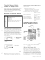
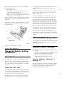
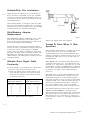
Diskette Description
The recording medium is a flexible, magnetic disk
enclosed in a protective jacket. The protected disk,
free to rotate within the jacket, is continuously
cleaned by the soft fabric lining of the jacket during
normal operation. Read/write/erase head access is
made through an opening in the jacket. Openings for
the drive hub and diskette index hole are also provided. The following figure is a drawing of the
diskette used with the IBM 5.25Inch Diskette Drive.
Oxide Coated
Mylar sy Disk
3.56 mm
CO.lpO in.)+--
Library.
4.
5.
6.
7.
8.
9.
10.
11.
12.
b. Insulation must not be frayed or worn.
Remove the back panel from the system unit.
Remove the five cover-mounting screws from the
rear panel, and remove the cover.
Check for any obvious non-IBM alterations. Use
good judgment as to the safety of any non-IBM
alterations.
Check inside the unit for any obvious unsafe conditions, such as metal filings, contamination, water
or other liquids, or signs of fire or smoke damage.
Check for worn, frayed, or pinched cables.
Ensure that the voltage specified on the voltage
tag (back panel of the machine) matches the
voltage of the power receptacle. If in doubt, the
voltage should be verified.
Examine the power supply and verify the following:
a. On universal power supplies, ensure that the
input voltage selection switch is set correctly.
b. Ensure that tamper-resistant fasteners in the
power supply cover have not been removed or
tampered with.
c. Ensure that the grommet is installed where
the internal power cables come through the
frame of the power supply.
Check for the following labels:
a. “Battery warning: Do not dispose of battery
unit in fire or water. See instruction for disposal in the battery installation instructions.”
b. Caution. Hazardous Area. Do not remove this
cover. Trained service people only. No serviceable components inside.
Check the condition of the battery.
Recording Medium
n
Write
Protect
Notch
\
Aperture
LEX41771
Figure l-l. 5.25-Inch Diskette, Simplified
lTrademark of E. I. du Pont de Nemours and Co., Inc.
Types of 5.25-Inch Diskettes
You can use the following types of diskettes to read
and write information:
l
l
l
Single-sided (160Kb/180Kb)
Double-sided (320Kb/360Kb)
High-capacity (1.2Mb).
It is important to remember that if you write on a
single-sided or double-sided diskette using a highcapacity diskette drive, you might not be able to read
the diskettes in a single- or double-sided diskette drive.
‘-i
1-2
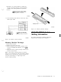
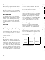
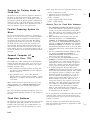
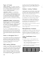
Types of 3.5-Inch Diskettes
will not have this selectable write protect interlock in
order to prevent accidental overwriting.
Distinguishing
features
Note: 720Kb diskette drives can use only the 1Mb
diskettes.
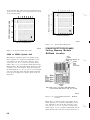
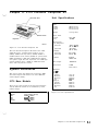
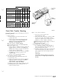
Media/Drive Compatibility
Table
I
720Kb diskette
Locking tab(In closed position,
allows writing
on diskette)
I
1.44Mb diskette
Locking tab
(In closed position,
allows writing
on diskette)
Note:
Format 1 .OMb media to 720Kb
Format 2.OMb media to 1.44Mb
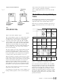
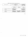
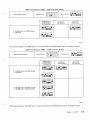
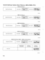
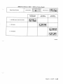
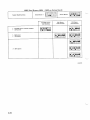
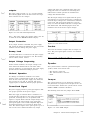
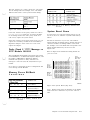
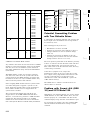
The following table identifies the minimum supported
level of DOS required to read, write, or format the
applicable media in the installed diskette drives.
DOS levels are downward compatible with respect to
diskette formatting; therefore, prior formats are supported.
77
Operation
LEX42345
Figure 1-2. 3.5Inch Diskette Types
The 3.5-inch diskette consists of a metal positive drive
disk attached to the bottom of the circular magnetic
recording surface. This assembly is permanently
encased in a hard plastic shell. The 1Mb and 2Mb
3.5inch diskettes can be differentiated by examining
the top surface of the plastic case. The 2Mb 3.5inch
diskette has the letters HD in the top upper right
corner of the plastic case and a square opening on the
top lower right corner. The 1Mb 3.5inch diskettes
have no such marking.
The slim, compact size of the 3.5inch diskette and the
permanent hard plastic shell in which it is encased
provide easy transportability. A metal shutter at the
front of the diskette covers and protects the magnetic
recording surface when the diskette is not in use.
When the diskette is properly inserted into the system,
metal shutter end first, the shutter is opened automatically to allow read or write activities. A write protect
sensor on the bottom of the plastic case can be positioned to protect the data stored on the diskette,
When the square opening on the top lower left corner
of the diskette is open (you can see through the hole),
the diskette is write protected and cannot be written.
The write protect interlock is located on the bottom
right corner of the plastic shell.
It is important to note that some 3.5-inch diskettes containing valuable programs, such as system diagnostics,
5.25-Inch
Drives
5.25-Inch
Drives
3.5-Inch
Drives
PCjrTM
PC
AT
XT 286
4865
XTTM
Portable
4869
Convertible
External
Internal
B
5.25-inch diskette formatted to:
160Kb
180Kb
320Kb
Read,
Write,
Format
DOS 1.00
DOS 3.00
DOS 1.00 NO
DOS 1.00 No
Read,
Write,
DOS 2.00
DOS 2.00
NO
Format
DOS2.00
No
Read,
Write,
Format
N/A
DOS 3.00
DOS 1.10 DOS 3.00
DOS 1.10 No
i DOS 1.10I No
360Kb
N/A
N/A
N/A
1.2Mb
N/A
3.5-inch diskette formatted to:
720Kb
Read,
Write,
Format
N/A
N/A
DOS 3.20
DOS 3.20
DOS 3.20
Figure 1-3. Media/Drive Compatibility Table
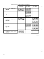
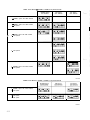
To use this chart, find your diskette drive and IBM
Personal Computer across the top of the table. Then,
coming down the left column, find your media. The
intersection of the read, write, format row and your
diskette drive and IBM Personal Computer column
identifies the minimum DOS level required to support
the function. Where N/A appears, it indicates either
unreliable operation will occur or the product cannot
perform the function.
Chapter 1. General Information 1-3
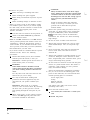
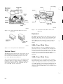
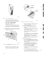
Diskette Care
The figure below shows proper and improper ways of
handling your diskettes. Proper handling will greatly
reduce the possibility of damaging them.
1. Wear the ESD wrist band any time ESD sensitive
devices are handled. This will place your body,
the option, and the system unit at the same ground
potential, thus preventing an accidental static discharge.
Proper
Improper
LEX40289
Don’t
Touch
Disk
Figure 1-6. Anti-Static Bag Removal
2. Carefully remove the option from its anti-static
bag. Be sure to grasp circuit boards by the edges
only; do not touch the component pins or solder
joints. Grasp diskette drives by their frames to
avoid touching the electronics board. Grasp chips
by their narrow ends only, not by their pins.
LEX40287
Figure 1-4. Diskette Handling Procedures
Handling Static-Sensitive
Devices
Some of the components that make up the options for
your IBM Personal Computer can be damaged by
electrostatic discharges. To prevent this damage, the
options are wrapped in a conductive, anti-static bag;
certain precautions must be taken before removing an
option from its bag:
LEX40290
Figure 1-7. Option Insertion
3. When inserting an option adapter into the system
board, hold the adapter by its top edge or upper
corners.
LEX40288
Figure l-5. Option Static Charge
1-4
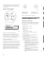
Chapter 2. 4860 PCjr
Modem
On/Off
Switch \
\
\w
I Power
Cassette
Serial
’ Direct
Drive
Video
Composite
Video
Light Pen ’
Television I
LEX40065
External
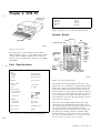
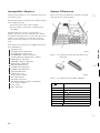
Figure 2-l. 4860 PCjr
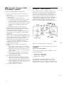
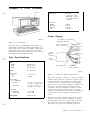
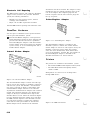
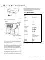
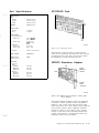
The 4860 is a low-cost, compact, desktop microcomputer. It is available in two models, the 04 and 67. It
utilizes an 8088 Microprocessor, 64Kb of random
access memory (RAM), and two cartridge slots. Features include a 360Kb disk drive and memory expansion up to 512Kb.
Top Cover
\
Figure 2-3. 4860 PCjr (Rear view)
Unit Specifications
Size
Height
Length
Depth
Infrared Receiver
Base
LEX40067
I
Diskette Drive
Weight
With Diskette Drive
W/o Diskette Drive
Environment
Air Temperature
System On
(Optional)
\
System Off
Cordless Keyboard
LEX40066
Figure 2-2. 4860 PCjr (Front view)
Humidity
System On
System Off
97 mm (3.8 in)
354 mm (13.9 in)
290 mm (11.4 in)
3.71 kg (8 lb 4 oz)
2.61 kg (5 lb 8 oz)
15.6” to 32.2”C
(60” to 90°F)
10” to 43°C
(50” to 110°F)
8% to 80%
8% tci 80%
Heat Output
283 BTU/hr max.
Noise Level
45 dBa
Electrical
Nominal
Minimum
Maximum
kva
120V AC
104V AC
127VAC
0.082 max.
Figure 2-4. 4860 System Unit Specifications
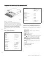
Chapter 2. 4860 PCjr
2-1
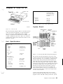
The system board contains the following major functional components:
Interface Locations
Interface.
Location
Compact printer
Compact printer
Diskette drive
Diskette-drive adapter
Display
System board and 64Kb memory
and display expansion
--
~~~
Graphics printer
Parallel printer attachment
Internal modem
Internal modem
Joystick
System board
Keyboard
System board
Light pen
System board
Memory
System board and 64Kb memory
and display expansion
I RS232C
Sound
.
.
.
.
.
.
.
.
.
.
.
.
.
.
.
.
.
System board
System board
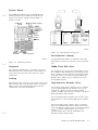
Figure 2-5. 4860 Interface Locations
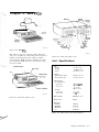
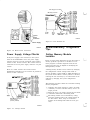
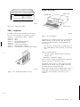
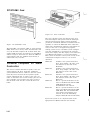
Power Supply
System Board
64Kb Memory
Expansion Connector
Internal Modem Connector
\
Infrared Receiver \
8088 Microprocessor
64Kb read-only memory (ROM)
128Kb ROM cartridge interface
64Kb dynamic RAM
64Kb memory and display expansion interface
Serial port (RS232)
Audio alarm (beeper)
Sound subsystem
Cassette interface
Joystick interface
Keyboard interface
Modem interface
Diskette interface
Video/graphics subsystem
Light pen interface
I/O expansion bus
9-level interrupt.
I I
I
Power Board
Connector
Left Side
I
;iii;i;re$jg
Grounding Pin
Connector
A10
Supply to
Diskette
Drive
Fan Plug
Al
LEX40069
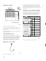
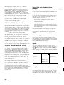
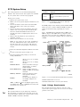
Figure
The system power supply is a 33-watt, three-voltagelevel, two-stage supply. The first stage is an external
power transformer that provides a single fuseprotected, extra-low, AC-voltage output. The second
stage is an internal, printed circuit board, which is
vertically mounted into the system board. The second
stage converts the transformer’s AC output into three
DC output levels.
Diskette Drive
y
Adapter Connector
LEX40068
Figure 2-6. 4860 System Board
2-2
2-7. 4860 Power Board (Component Side)
Power is supplied to the system board through a
printed circuit board edge connector. The diskette
drive is powered through a separate 4-pin connector
mounted on the front edge of the power board. The
power for the diskette drive fan is provided by a 3-pin,
Berg-type connector mounted directly below the
diskette drive connector. Power is removed from the
system board and diskette drive by a switch mounted
on the rear of the power board. Both the switch and
the transformer connector are accessible from the rear
of the system.
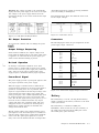
General Information
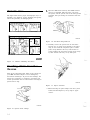
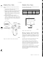
Cordless Keyboard
Connector Guides
LEX41744
Figure 2-8. 4860 Cordless Keyboard
The keyboard is a low-profile, 62-key, detached keyboard with full-travel keys. The keys are arranged in a
standard typewriter layout with the addition of a function key and cursor-control keys.
The keyboard is battery powered and communicates to
the system unit with an infrared (IR) link. The IR link
makes the remote keyboard a truly portable hand-held
device. An optional cord connection to the system
unit is available. Power is sent to the keyboard and
serially encoded data is received by the system unit
through the optional cord. When connected, the cord’s
keyboard connector removes the battery power, and
the -CABLE CONNECT signal disables the infrared
receiver circuit. The disabling of the circuit also
allows other infrared devices to be used without interfering with the system. The data, which is received
through the IR link or by the cord, have the same
format.
The keyboard electronics are designed with low-power,
complementary metal-oxide semiconductor (CMOS)
integrated circuitry for battery power operations.
Four AA-size batteries are required. Because the keyboard is normally in the standby power-down mode,
which uses very little power, no on/off switch is
needed.
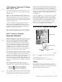
PCjr connector guides help eliminate the possibility of
connector pins being broken on the 4860 PCjr Planar
Board. The connector guides snap into the back cover
of the system unit. The installation of these guides
requires no tools; however, the system unit and
attached devices must be powered off, as the cables
need to be removed to facilitate installation of the
guides. P/N6447163 provides guides along with
instructions necessary for installation. The part is a
no-cost item and can be ordered through normal parts
distribution. If system unit diagnostics require the use
of service plugs, the connector guides must be carefully removed and reinstalled at the completion of the
repair activity.
PCjr Diskette Drive. Inserts
There is no specified part number for a shipping insert
for the PCjr diskette drive. Use the generic insert
P/N6447190 available from distribution. Trim off
approximately 0.5 inch, or remove the back tab of the
generic insert. This will allow clearance for the latch
lever to swing into the lock position without interference.
4860 PCjr Diagnostics
Error Codes
You might have an error code or an audio response
during the power-on self test (POST). If you have both
an error code and an audio error, disregard the audio
error and perform advanced diagnostics on the FRU
indicated.
The 4860 Keyboard was manufactured in two versions.
The old Chicklet version was replaced with the version
that is currently in use. The new keyboard is electronically identical to the older version but is improved
mechanically for easier use. It has bigger keys that
are easier to press, and the key designations are on the
key tops rather than printed on the keyboard itself.
The 4860 Keyboard is a field replaceable unit (FRU);
nothing on it can be repaired. Batteries in the keyboard are the customer’s responsibility. A failing keyboard should be replaced.
Chapter 2. 4860 PCjr
2-3
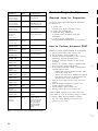
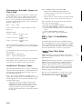
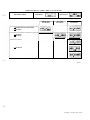
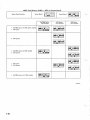
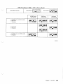
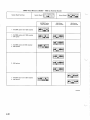
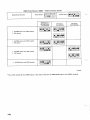
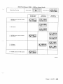
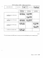
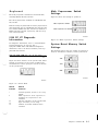
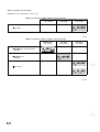
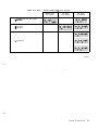
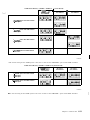
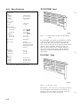
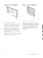
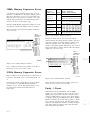
POST Error
Problem
Area
Probable Cause
No beep. No
image or image
on screen wrong.
Power
System Board or
Power Board
One beep. No
image or image
on screen wrong.
Display
System Board or
64Kb Memory and
Display Expansion
Two beeps. No
image or image
on screen wrong.
Power
System Board or
Power Board
Three beeps.
No image or
image on
screen wrong.
Memory
64Kb Memory and
Display Expansion
Advanced POST
or portion of it
goes into loop.
System
Board
System Board
No beep.
ERROR OAXX
Memory
System Board
No beep.
ERROR OBXX
Memory
64Kb Memory and
Display Expansion
No beep.
ERROR OCXX
Memory
64Kb Memory and
Display Expansion
No beep.
ERROR 1YXX
Memory
System Board
No beep.
ERROR 2000
Keyboard
Keyboard
No beep.
ERROR 21XX
Infrared
Infrared Receiver
No beep.
ERROR 22XX
Keyboard
Keyboard
No beep.
ERROR 23XX
Cassette
or Serial
System Board
No beep.
ERROR 24XX
Modem
Internal Modem
No beep.
ERROR 25XX
Cartridge
No beep.
ERROR 26XX
Diskette
Drive
Diskette Drive
Adapter
No beep.
ERROR 27XX
Cluster
Cluster Adapter
No beep.
ERROR 28XX
Speech
Speech
Adapter
Any ERROR
message not
listed in
this table.
Service
Plug
Ensure that
Service Plug is
good and installed
correctly. Repeat
advanced POST.
General Diagnostic Tips
Required Items for Diagnostics
In order to perform all of the advanced diagnostics,
you must have:
l
.
l
l
l
l
If same message,
replace System
Board.
Figure
2-4
2-9. 4360 PCjr Advanced POST Error Table
l
A system unit
A known good display television receiver
A service plug, P/N6447196
A POST-loop plug, P/N6447197
A parallel printer attachment wrap plug,
P/N8529228
A serial wrap plug, P/N6447198
A Triplet Model 310 Multimeter (or equivalent).
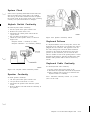
How to Perform Advanced POST
Before you perform advanced POST, do the following:
1. Set the system unit’s power switch to off.
2. Set the display’s power switch to off.
3. Connect the power transformer’s power cord to a
functioning, properly grounded outlet.
4. Install all connectors securely in their proper
locations.
5. Remove any cartridge, cassette, or diskette from
the system unit and attached devices.
6. If the cordless keyboard is being used without its
optional keyboard cord:
l
Position the keyboard within 12 inches of the
front of the system unit.
l
Remove any obstructions between the infrared
(IR) emitter in the back of the keyboard and
the IR receiver on the system unit.
7. Plug the service plug into the system unit J connectors.
8. Turn the display’s brightness, contrast, and
volume controls to midrange.
9. Set the display’s power switch to on.
10. Set the system unit’s power switch to on.
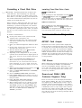
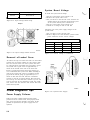
Advanced POST begins as soon as the system unit
power switch is set to on. It takes as long as 1 minute
to complete. While advanced POST is running:
l
You see a stable IBM logo and 16-color test
pattern on your screen.
-)I$-
_; +;$I’‘-
-;L$-
LEX40136
Figure 2-10, Screen Test Pattern
If advanced POST detects a failure, you will receive an
incorrect audio response (no beep, two beeps, or three
beeps), an incorrect screen, an error message, or any
combination of these. In these cases, see Figure 2-9 on
page 2-4 for the recommended action.
After you have followed the above steps once, all you
have to do when asked to perform advanced POST is:
1. Set the system unit’s power switch to off.
2, Wait 5 seconds.
LEX40137
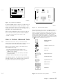
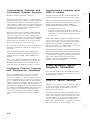
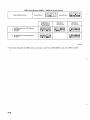
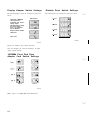
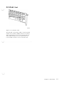
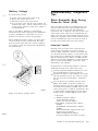
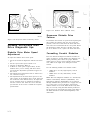
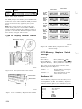
Figure 2-11. Advanced-Test Menu
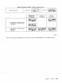
The advanced-test menu consists of symbols, with each
symbol representing one area of the IBM PCjr. The
letters or numbers below the symbols are IDs of tests
you can perform, A quick way to determine if you are
looking at the advanced-test menu or the customerlevel-test menu (they look similar) is to observe the ID
under the joystick symbol. The advanced-test level has
an E there. The customer-level has a 6.
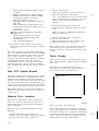
How to Perform Advanced Tests
Advanced tests are the tests you choose from the
advanced-test menu. The advanced-test menu is stored
in the system unit’s read-only memo ry (ROM).
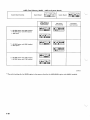
Diskette- Drive Test
Type MPNP
..
*
Display and Light Pen Test
When you are asked to bring up the advanced-test
menu, follow these steps:
1. Set the system unit’s power switch to on.
2. Wait until advanced POST completes and the
BASIC screen appears.
3. Press and hold the Ctrl and Alt keys, and then
press the Ins key.
4. Release all keys when the screen goes blank.
0
I
/
Joystick Test
A
IEiA
Sound Test
Graphics Printer Test
Internal Modem Test
The IBM logo appears, the diskette drive (if attached)
red light switches on for a moment, and you hear one
beep. Then the advanced-test menu appears.
Compact Printer Test’
RS232
Serial Port Test
p=@q
Keybdard Test
Cluster Test
LEX40138
Figure Z-12. Advanced Test Symbols
Chapter 2. 4860 PCjr
2-5
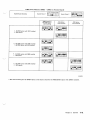
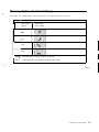
Some symbols and IDs appear on the advanced-test
menu only when their particular options are attached
to the system unit.
If you see an * in the lower right-hand corner of the
advanced-test menu, the menu has another page of
symbols. When the cursor is moved to the last ID on
the screen, moving it again causes this next menu page
to appear.
On the last menu page, an Q is in the lower right-hand
corner. When the cursor is moved to the last ID on
this screen, moving it again causes the first menu page
to reappear.
c
The diskette drive interface is on the diskette drive
adapter. The ID under the diskette drive symbol therefore blinks only when the diskette drive adapter is
installed.
The IDs 4 and 5 under the display symbol blink all the
time. ID 8 blinks when the 64Kb memory and display
expansion is present.
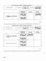
While the advanced-test menu is on your screen, a
memory test is running continuously. The number
incrementing at the bottom of the screen shows what
segment of memory is being tested. If a memory
failure is detected, the number stops incrementing and
the * next to it is replaced by an error message. If this
failure occurs, make a note of the error message and
go to PIC “Memory.”
RS232
q
The IDs for joystick and sound always blink because
their interfaces are on the system board, The blinking
does not mean a joystick or external speaker is
installed.
-; i’
LM
LEX40139
Figure 2-13. Last Menu Page
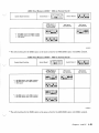
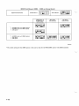
When the IBM PCjr senses the presence of a device
interface, the ID under the symbol for that device
blinks. The device interface is the electronic circuitry
necessary for the system unit to control a particular
device. In Figure 2-14, the interfaces for diskette
drive, display, joystick, and sound are sensed.
-;$\
64 KB ’ XX YY XX
LEX40141
Figure 2-15. Memory Segment Testing
You move the cursor to the test’s ID by pressing the
Ins key. When you are ready to start the test, press
the Enter key and the test begins.
*_ >
E < ._
.’ I’,
-,+,
‘;(i-
G
The test is finished when a message appears under the
symbol’s ID. If * appears, no failure was detected.
*
64 KB ’
LEX40140
Figure 2-14. Interface Device Sensory
2-6
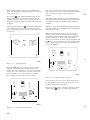
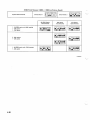
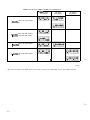
Customer Error Codes
f
?
cl
-$I:-
When requesting service, customers may reference an
error code found in the Error Message Table on page
6-17 of the Guide to Operations (GTO) manual. These
are not advanced diagnostic error codes and cannot be
found in the Hardware and Maintenance Service (HMS)
manual. A list of the codes follow:
a
.‘I’,
-,$, y-i-
G
WC
64 KB ’ XX YY X X
LEX40142
Figure 2-16. Test Completion
Error
A
D
G
X
Action
Have system
serviced.
B
Keyboard problem;
move away fram
bright light.
c
Cassette problem;
if the cassette is not
in use, press Enter
and continue.
E
Modem problem; if
modem is not required,
press Enter to
continue.
If something other than * appears, a failure was
detected.
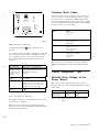
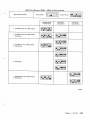
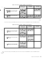
If you want to stop a test that is running, press the FN
key, and then press the B key. Depending on which
test is running, you can get one of several responses
after pressing FN-B. The following table lists the
responses.
I
I
Test Running
Response to Pressing FN-B
Diskette drive
Graphics printer
Compact printer
Internal modem
Sound
(If the system unit beeps, press
FN-B again.) Test may not stop
immediately. Message is
“FFFF.”
Display
RS232
Keyboard
Joystick
Light pen
These errors are for reference only. Actual failures
should be determined by using the advanced diagnostics.
Power Diagnostic Tips
Test stops immediately. Message
I is “FFFF.”
I
The FN and B keys must be
shown on the screen before using
them to abort the test. Test stops
immediately. Message is *.
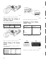
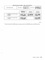
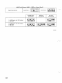
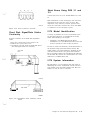
The voltages at the diskette drive power cable connector on the power board should be within the ranges
listed below.
Test stops immediately. Message
I is *.
Diskette Drive Voltage at the
Power Board
I
Figure 2-17. Response Messages
The “FFFF” message lets you know that the test was
stopped before completion.
Pin 1 to Pin 2
Pin 4 to Pin 3
Figure
Low V DC
High V DC
+ 11.4
i-4.7
+ 12.6
+ 5.3
2-18. Diskette Drive Power Board Voltage
Levels
When you want to remove the advanced-test menu
from your screen, press and hold the Ctrl and Alt keys,
and then press the Del key,
Chapter 2. 4860 PCjr
2-7
LEX40143
Figure 2-19. Diskette Drive Pin Placement
LEX40145
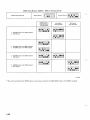
Diskette Drive Fan Voltage at
the Power Board
Figure 2-23. Display Board Pin Placement
The voltages at the diskette drive fan connector on the
power board should be’ within the ranges listed below.
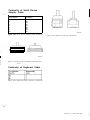
Continuity of Color Display
Adapter Cable
1 LowV DC 1 HighV DC
I
Pin 2 to Pin 1
Pin 2 to Pin 3
Figure
+ 11.4
+ 11.4
I
+ 12.6
+ 12.6
2 x S-pin Connector
to Position
S-pin Connector
from Position
2-20. Fan Power Board Voltage Levels
B9
B5
I A5
Al
A4
A6
1
2
3
4
5
6
Not used
I
B3
B1
8
9
Figure 2-24. Color Display Adapter Cable Connections
LEX40144
Figure
2-21. Fan Power Board Pin Placement
Display Voltage at the System
Board
The voltages at connector D should be within the
ranges listed below.
l-l
I
\
L
I
A.
B
1
9
LEX40146
Figure 2-25. Color Display Connector Locations
Figure 2-22. Display Board Voltage Levels
2-8
I
Continuity of Serial Device
Adapter Cable
I
25-pin Connector
from Position
2 x S-pin Connector
to Position
1
B1
A4
AS
A3
A7
A6
B2
A5
A2
2
3
4
5
6
7
8
20
3
2
1
1
6
LEX40148
Figure 2-26. Serial Device Adapter Cable Continuity
Figure 2-29. Keyboard Cable Pin Placements
LEX40147
I
Figure
2-27. Serial Device Adapter Cable Pin Placement
Continuity of Keyboard Cable
;
Figure 2-28. Keyboard Cable Continuity Connections
Chapter 2. 4860 PCjr 2-9
Chapter 3. 5140 PC Convertible
Unit Specifications
Size
Height
Length
Width
68.0 mm (2.68 in)
374.0 mm (14.72 in)
312.0 mm (12.28 in)
Weight
5.5 kg (12.17 lb)
Environment
Air Temperature
System On
System Off
Humidity
System On
System Off
LEX41040
10” to 40°C
(50” to 105°F)
0.6” to 51.7”C
(33 to 125°F)
5 to 95%
5 to 95%
{AC adapter input range}
90.265V, 50/60 Hz AC
Electrical
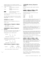
Figure 3-l. 5140 PC Convertible
Figure 3-2. 5140 Specifications
System Information
The IBM 5140 PC Convertible is a portable personal
computer designed for professional applications and
personal productivity. It is designed to enhance personal computing capability with multiple power
options. The uniqueness of the system unit is the integration of microprocessor, display diskette drives, keyboard, memory, battery power supply, and optional
modem within a full function system that can be
carried in one hand and used in most environments.
The IBM 5140 maintains compatibility with 5.25inch
drive systems through asynchronous communications
and 3.5inch drive options (IBM 4865) on existing PCs.
The IBM PC Convertible features an 8OC88 Microprocessor and 256Kb of user memory. User memory
can be expanded to 512Kb with the addition of 128Kb
memory cards installed by the user. The 3.5-inch
diskette drive is a double-sided drive with 720Kb of
(formatted) storage capacity.
The 80-column x 25-line detachable liquid crystal
display features a bonding process that reduces glare
and increases visibility.
Power Sources
Several sources for power are available for the 5140 PC
Convertible. They are:
IBM PC Convertible AC Adapter
The AC Adapter is designed to be used by the system
while simultaneously charging the internal battery.
The AC Adapter supports 11OV AC or 220V AC operation.
Battery Pack
The battery pack contains eight rechargeable NiCad
cells packaged into a single unit. It resides inside the
system unit and plugs onto the power supply card
under the unit’s covers. When fully charged, the
battery pack will provide approximately eight hours of
operation. This time will vary depending upon the
amount of usage of the higher consumption devices,
such as diskette drives.
Chapter 3. 5140 PC Convertible
3-I
IBM PC Convertible Battery
Charger
IBM PC Convertible Color
The battery charger is designed to be used to trickle
charge the internal batteries of the system. It does not
provide sufficient power output to allow system operation while the batteries are being charged.
The IBM PC Convertible Color Display is a 13-inch
RGBI direct drive display with 320 x 200 lines graphics
support and text modes of 40 x 25 and 80 x 25. The
display includes a speaker for external audio output.
IBM PC Convertible Automobile
Power Adapter
IBM PC Convertible Cathode
Ray Tube (CRT) Display Adapter
The Automobile Power Adapter is designed to power
the system unit while simultaneously charging the
system battery pack. The adapter attaches to the
system unit and plugs into the cigarette lighter outlet
in a vehicle with a 12V negative-ground electrical
system.
The IBM PC Convertible CRT Display Adapter
attaches to the IBM PC Convertible and is operable
when the system is powered with the AC Adapter. The
IBM PC Convertible Monochrome Display, the IBM
PC Convertible Color Display, the IBM Personal Computer Color Display, and the IBM PCjr Color Display
are supported.
Options
IBM PC Convertible Internal
Modem
Monitor Adapter
Parallel Printer Adapter
The IBM PC Convertible Internal Modem gives users
the capability of communication between the IBM PC
Convertible and other compatible systems over
existing telephone lines at speeds of either 300 or 1200
baud.
IBM PC Convertible
Serial/Parallel Adapter
LEX41041
Figure 3-3. Option Configuration
IBM PC Convertible Printer
The IBM PC Convertible Printer is a matrix printer
designed to attach to the back of the IBM PC Convertible and to draw its power from the system unit’s
battery pack. An all-points-addressable (APA) mode is
provided for graphics.
IBM PC Convertible
Monochrome Display
The IBM PC Convertible Monochrome Display is a
9-inch composite video display with 80 x 25 and 40 x 25
text modes and 640 x 200 and 320 x 200 graphics
support.
The IBM PC Convertible Serial/Parallel Adapter provides an RS232C asynchronous communications interface and a parallel printer interface.
Supported Options
The IBM Personal Computer options that are supported on the IBM 5140 are:
IBM
9 IBM
l IBM
. IBM
l IBM
l IBM
l
5152 Graphics Printer
4201 Proprinter
Personal Computer Printer Cable
5153 PC Color Display
4863 PCjr Color Display
Communications Adapter Cable.
Diagnostic Tip
Error Code 5103
When running diagnostics on the 5140 PC and it
responds with a 5103 error, make sure that there is
paper in the printer, the ribbon is installed correctly,
and the ribbon cassette is not out of ribbon, Any of
these conditions can cause a 5103 error.
-_
- /
LJ
Chapter 4. 5150 PC
Diskette Drive
Electrical
Nominal
Minimum
Maximum
kva
120V AC
104V AC
127V AC
0.22 max.
Figure 4-2 (Part 2 of 2). 5150 PC1 Specifications
System Board
Keyboard
Cassette
System Expansion Slots ,
\\
Keyboard ’
Math
/Coprocessor
System
Board
Power
Connections
LEX40671
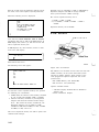
Figure
4-l. 5150
PC
The 5150 PC uses a 16-bit 8088 Processor, 16Kb to
640Kb of RAM. It uses 0, 1, or 2 diskette drives with a
storage range of 160Kb to 320Kb. The 5150 has five
I/O slots and a 4-channel direct memory access (DMA)
40Kb ROM.
‘;
,
16-64K CPU or
8088
Processor
Switch
Block 2
Switch
Block 1
Unit Specifications
Modules
System Unit
Size
Height
Length
Depth
142 mm (5.5 in)
500 mm (19.6 in)
410 mm (16.1 in)
Weight
11.4 kg (25 lb)
Power Cable
Length
Size
1.83 m (6 ft)
18 AWG
Environment
Air Temperature
System On
System Off
Humidity
System On
System Off
15.6” to 32.2”C
(60” to 90°F)
lo” to 43°C
(50” to 110°F)
8% to 80%
20% to 80%
Heat Output
365 BTU/hr max.
Noise Level
56 dBa
Figure 4-2 (Part 1 of 2). 5150 PC1 Specifications
L__/’
Color
Trimmer
Capacitor
Pin 1 / \Speaker\ Cassette Microphone
Output
or Auxiliary Select
LEX40072
Figure 4-3. 5150 System Board
The system board fits horizontally in the base of the
system unit. It is a multilayer, single-land-per-channel
design with ground and internal planes provided. DC
power and a signal from the power supply enter the
board through two 6-pin connectors. Other connectors
on the board are for attaching the keyboard, audio cassette, and speaker. Five 62-pin card edge sockets are
also mounted on the board. The I/O channel is bussed
across these five I/O slots.
Two dual in-line package (DIP) switches (two eightswitch packs) are mounted on the board and can be
read under program control. The DIP switches provide
the system software with information about the
installed options, how much storage the system board
has, what type of display adapter is installed, what
operation modes are desired when power is switched
on (color or black-and-white, 80- or 40-character lines),
and the number of diskette drives attached.
Chapter 4. 5150 PC 4-1
The system board consists of five functional areas: the
microprocessor subsystem and its support elements, the
read-only memory (ROM) subsystem, the read/write
(R/W) memory subsystem, integrated I/O adapters, and
the I/O channel. The read/write memory is also
referred to as random access memory (RAM).
Microprocessor
The heart of the system board is the Intel 8088 Microprocessor. This is an 8-bit external-bus version of
Intel’s 16-bit 8086 Microprocessor and is softwarecompatible with the 8086. Thus, the 8088 supports
16-bit operations, including multiply and divide, and
supports 20 bits of addressing. It also operates in
maximum mode, so a co-microprocessor can be added
as a feature. The microprocessor operates at 4.77
MHz.
Power Supply
5-l /4 Inch Diskette Drive
Power C nnectors
R
+ 5V DC, 2 A at +12V DC, 0.3 A at - 5V DC, and 0.25 A
at -12V DC. These outputs are overvoltage, overcurrent, open-circuit, and short-circuit protected. If a DC
overload or overvoltage condition occurs, all DC
outputs are shut down as long as the condition exists.
The + 12V DC and -12V DC power the EIA drivers and
receivers on the Asynchronous Communications
Adapter.
The + 12V DC also powers the system’s dynamic
memory and the two internal 5.25-inch diskette drive
motors. It is assumed that only one drive is active at a
time. The +5V DC powers the logic on the system
board and diskette drives and allows about 4 A of + 5V
DC for the adapters in the system-unit expansion slots.
The -5V DC is for dynamic memory bias voltage; it
tracks the + 5V DC and + 12V DC very quickly at
power on and has a longer delay on power off than the
+ 5V DC and + 12V DC outputs. All four power supply
DC voltages are bussed across each of the five systemunit expansion slots.
Keyboard
The IBM Personal Computer keyboard has a permanently attached cable that connects to a DIN connector at the rear of the system unit. This shielded
5-wire cable has power (+5V DC), ground, two
bidirectional signal lines, and one wire used as a reset
line. The cable is approximately 182.88 cm (6 ft) long
and coiled, like that of a telephone handset.
Power
On/Off
\
System Unit
Power Connector
IBM Monochrome Display
Power Connector
(Internally Switched)
\
System Board
Power Connector
LEX40073
Figure 4-4. Power Supply
The system power supply is located at the right rear of
the system unit. It is an integral part of the systemunit chassis. Its housing provides support for the rear
panel, and its fan furnishes cooling for the whole
system.
It supplies the power and reset signal necessary for the
operation of the system board, installed options, and
the keyboard. It also provides a switch AC socket for
the IBM Monochrome Display and two separate connectors for power to the 5.25inch diskette drives.
The two different power supplies available are
designed for continuous operation at 63.5 watts. They
have a fused 120V AC or 220/240V AC input and
provide four regulated DC output voltages: 7 A at
4-2
i/
L
The keyboard uses a capacitive technology with a
microprocessor (Intel 8048) performing the keyboard
scan function. The keyboard has two tilt positions for
operator comfort (5 or 15-degree tilt orientation).
The keyboard has 83 keys arranged in three major
groupings. The central portion of the keyboard is a
standard typewriter keyboard layout. On the left side
are 10 function keys. These keys are defined by the
software. On the right is a l5-key keypad. These keys
are also defined by the software but have legends for
the functions of numeric entry, cursor control, calculator pad, and screen edit.
The keyboard interface is defined so that system software has maximum flexibility in defining certain keyboard operations. This is accomplished by having the
keyboard return scan codes rather than American
Standard Code for Information Interchange (ASCII)
codes. In addition, all keys are typematic (if held
down, they will repeat) and generate both a make and
a break scan code. For example, key 1 produces scan
code hex 01 on make and code hex 81 on break. Break
codes are formed by adding hex 80 to make codes. The
keyboard I/O driver can define keyboard keys as shift
keys or typematic, as required by the application.
L._L
1
“i//
The microprocessor in the keyboard performs several
functions, including a power-on self test when
requested by the system unit. This test checks the
microprocessor ROM, tests memory, and checks for
stuck keys. Additional functions are keyboard scanning, buffering of up to 16 key scan codes, maintaining
bidirectional serial communications with the system
unit, and executing the handshake protocol required
by each scan-code transfer.
Vertical Mounting Not
Supported
IBM does not support operating the 5160 in a vertical
position. Loss of customer data could occur if the
system is operated in this manner.
Power Diagnostic Tips
5150/5160-Based System
Diagnostics
_
General Diagnostic Tips
Power-On Self Test
Each time you set the system unit’s power switch to
on, the power-on self test (POST) executes. The POST
takes 13 to 90 seconds to complete, depending on the
options installed.
The POST checks the following:
id
. System board
. Memory expansion adapters
.
.
.
.
Keyboard
Primary display
Diskette drive and adapter
Fixed disk drive and adapter (if available).
To start the POST:
\_;
1. Turn on all external devices, including printer,
display, and plotter.
2. Set the power switch on the expansion unit (if
attached) to on.
3. Set the system unit power switch to on.
4. Turn the brightness and contrast knobs fully
clockwise. (If you have a color monitor, ensure
that it is set to on.)
5. Watch (and listen) for the following responses:
a. A cursor appears on the display in approximately 4 seconds.
b. While the memory is being tested, the memory
size appears in the top left corner of the
screen and increases in 64Kb increments until
the total system memory is tested. This is not
applicable to the 5150 PC.
c. One short beep is heard when the POST is successfully completed.
d. The IBM Personal Computer basic screen
appears if a diskette or an operating system is
not automatically loaded from a fixed disk
drive.
Dead Machine Tips
Verify that the outlet has good power and that
power cord is good.
Disconnect all external I/O cables from PC
(external I/O may cause power problems).
If installed, remove the math coprocessor.
Remove disk drive power connectors one at a time
from the disk drive logic board (a failing logic
board may cause power problems).
Check voltages exiting power supply to system
board.
Check system board ohm resistance.
System Board Power
1. Set the power switch on the system unit to off.
2. Set your meter to the 12V DC scale.
3. Refer to Figure 4-6 on page 4-4 and connect the
common lead to pin 5 and the voltage lead to pin 1
of the system board power connector.
4. Set the power switch on the system unit to on.
5. Check for a voltage reading of 2.4V DC to 5.2V
DC.
Leave your meter set on the 12V DC scale and check
the rest of the power supply voltages to the system
board (see Figure 4-5.)
Voltage Connectors
Min V DC
Max V DC
-Lead
+ Lead
+ 4.8
+5.25
5
10
+ 4.6
+ 5.5
9
6
+ 11.5
+ 12.6
7
3
+ 10.9
+ 13.2
4
8
Figure 4-5. Power Supply Voltages
Chapter 4. 5150 PC
4-3 44443
Power Supply Fan Connector
PIN 2. GROUND
&PINl,-12VDC
PIN 2, GROUND
PIN 1. +12V DC
PIN 4, +5V DC
PIN 3, GROUND
PIN 2, GROUND
PIN 1, +12V DC
PIN 4. +5V DC
PIN 3, GROUND
PIN 2, GROUND
PIN 1, +12V DC
PIN 6, +5V DC
PIN 5, +5V DC
PIN 4, +5V DC
PIN 3. -5V DC
PIN 2, GROUND
IBM Display Connector
Power Connectors
Power Connectors
Key
FIM
PIN
PIN
PIN
PIN
PIN
System
Board
Connectors
\ Power Supply
LEX40155
Figure 4-6. Board Power Connectors
Power Supply Voltage Checks
If the power supply is not connected, to the system
board or the disk/diskette drives, the power supply
voltages cannot be correctly measured unless loaded
with a 1.5-ohm, 25-watt resistor. The resistor must be
connected across the power supply connector P 9 pins
1 and 6.
There is a 3-ohm, 25-watt wire-wound resistor
P/NO337213 available. Use two resistors in parallel to
obtain 1.5-ohms resistance.
5.25-Inch
_ Diskette Drive
‘d
br wti/%
5: GROUND
4, -12V DC
3, +12V DC
2. KEY
1, PWR GOOD
LEX40157
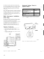
Figure 4-8. 5155 Portable P C
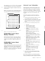
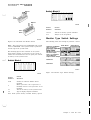
System/Memory Diagnostic
Tips
Failing Memory Module
Isolation
There are times when diagnostics do not show when a
memory problem is present on a machine. If a customer program or another diagnostic fails, the following procedure may be helpful in identifying the
failing memory module.
A failing memory module can be isolated by changing
the configuration switch settings. Each bank of
memory modules is either 64Kb or 16Kb depending on
the system board. When a memory failure is detected,
reducing the size of memory by an entire bank can be
achieved by changing the system configuration
switches.
The following procedure should be used while running
memory diagnostics:
Configure the switch settings to reduce one bank
of memory at a time until the memory error is no
longer present.
When the error is no longer present, the last bank
of modules eliminated is the failing bank.
The failing module can be identified by configuring the machine back to the switch settings of
the last failure. Then, swap out individual
modules of the failing bank until the error goes
away.
System Unit
Power Connector
IBM. Monochrome Display
Power Connector
(Internally Switched)
\
LEX40156
Figure 4-7. Voltage Checks
4-4
\
LJ
U
Hardware Maintenance and Service (HMS) manual
maintenance analysis procedures (MAP S) for bank and
module locations.
Potential Memory Module
Problem on Adapter Cards
Replace adapter cards containing potentially defective
soldered memory modules and pluggable memory
modules on the Enhanced Graphics Adapter (EGA)
Expansion card when diagnostics indicate an adapter
or memory module failure.
l
EGA Memory Expansion card
(P/N6323468) has pluggable memory modules
(P/N8854219) located in bank 01, 02, and 03.
The following adapters have soldered modules:
Modules Positions
Machines and Devices Affected
EGA Card (P/N8654215)
Type
Device Description
4450
4455
5150
5160
5161
5170
5271
5273
5373
5531
7531
7532
EGA Expansion Card
EGA Card
PS AT Card
PS XT Card
Extended Graphics Adapter (XGA) Card
All Points Addressable (APA) Card
APA Card (P/N8654390)
PS XT Card (P/N8654381)
XGA AT Card (P/N2683118)
U1, 2, 10, 11, 40, 41,
50, and 51
U65, 78, 91, and 103
U10, 23, 36, 49, 62,
and 75
U11, 12, 24, 25, 38,
39, 52, 53, 63, 64, 74,
and 75.
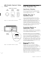
5150/4450 Failing Memory
Module Bit/Bank Location
Replace memory modules numbered 8535 through 8544
that are labeled plant code G when diagnostics indicate a memory module or adapter failure. When the
memory modules are soldered, refer only to the number
code 8635 through 8544 on the top of the memory
module and replace the adapter card if applicable.
When the memory modules are pluggable, refer to both
top and bottom view and replace all of the affected
modules during a repair action. The affected modules
do not affect data.
Connections
16-64K CPU or
64Kb-256Kb
Output
Top View
LEX40149
ii
uuuuuuuu
Figure 4-9. 5150/4450 Memory Module Bit/Bank
Location
G = Plant Affected
16Kb to 64Kb System Unit
I
Bottom View
LEX41870
i‘__/’
64Kb memory module locations are designated by
location numbers on the adapter card. Refer to the
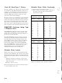
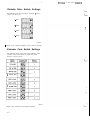
When there is a memory failure, the address of the
failure appears as a 4-character alphanumeric error
code, followed by 201. If the first character of the
error code is 0, you have a system board failure. The
second character 0, 4, 8, or C indicates which bank has
the failing module. The third and fourth characters of
the 4-character error code indicate which bit (module)
of the bank failed (P, 0, 1, 2, 3, 4, 5, 6, 7). For example,
Chapter 4. 5150 PC 4-5
error code OC40 201 means that the module indicated
by the arrow in Figure 4-10 on page 4-6 (bank 3, bit 6)
is the one that failed.
(Last 2 characters of error code)
Top View of System Board
(Last 2 characters
LEX40151
of error code)
Top View of System Board
Figure 4-l . . System Board (Top View)
LEX40150
Figure 4-10. System Board (Top View)
64Kb to 256Kb System Unit
5160/5155/XT370/5531/4455
Failing Memory Module
Bit/Bank Location
Color
Trimmer
When there is a memory failure, the address of the
failure appears as a 4-character alphanumeric error
code, followed by 201. If the first character of the
error code is 0, 1, 2, or 3, you have a system board
failure. The 0, 1, 2, or 3 indicates which bank has the
failing module. The third and fourth characters of the
4-character error code indicate which bit (module) of
the bank failed (P, 0, 1, 2, 3, 4, 5, 6, or 7). For example,
error code 3040 201 means that the module indicated
by the arrow in Figure 4-11 (bank 3, bit 6) is the one
that failed.
/
\
Capacitor Keyboard I/O
/
System
Board
Power
Connections
Speaker
Output
Note: Banks 0 and 1 may contain 256K RAM modules
on 5160 modules 088, 089, 267, 268, 277, and 278.
LEX41700
Figure 4-12. 5160/5155/XT370/5531/4455
Location
Bit/Bank
When there is a memory failure, the address of the
failure appears as a 7-character alphanumeric error
code, followed by 201. If the first character of the
error code is 0, 1, 2, or 3, you have a system board
failure. The 0, 1, 2, or 3 indicates which bank has the
failing module. The sixth and seventh characters of
4-6
I
L
\>
the 7-character error code indicate which bit (module)
o f the bank failed (P, 0, 1, 2, 3, 4, 5, 6, 7). For example,
error code 3COO0 40 201 means that the module indicated by the arrow in Figure 4-13 (bank 3, bit 6) is the
one that failed.
Memory error, memory lock, or a blank display may
occur if you plug one or more chips in wrong when you
are replacing the system board or system memory.
Bits
Interrupt Level Information
Interrupt levels are used by PCs to prioritize operations. Diagnostics will not necessarily fail on a PC
with interrupt conflicts, yet the operator will keep
getting errors. Although the customer is responsible
for solving interrupt conflicts, an IBM service representative can use this information to reduce diagnostic
time, NTFs, unnecessary parts replacements, and
callbacks.
To determine whether an unusual PC problem is
caused by conflicting interrupt levels, follow these
steps:
A.
B.
C.
Load the advanced diagnostics diskette, go to the
list of installed devices, and copy that list.
Examine the adapter cards installed in the system
unit and expansion unit. If any cards are located
that are not on the list from Step 1, add them to
the list.
Sort the list into the following interrupt levels:
1.
2.
00
01
02
04
08
Front
IO
20
40
80
*
3.
\iQj
LEX40153
Figure 4-13. System Board (Top View)
256Kb/640Kb System Board
Memory Problems
4.
The E-2 jumper located next to the power supply on
the system board is needed to support 256Kb modules
in banks 0 and 1. Without this jumper, 640Kb on the
system board will appear in POST and diagnostics as
256Kb.
5.
256Kb/640Kb System Board
Labeled Wrong
6.
7.
PC XT 5160s (Models 088, 089, 267, 277, 278) have some
system boards labeled wrong. The boards are labeled
64Kb/256Kb. They should be labeled 256Kb/640Kb. A
256Kb/640Kb board can be identified by looking for the
presence of a module in position U84. The 64Kb/256Kb
board has no module in this position.
D.
Kevboard
Enhanced Graphics Adapter
3278/79 Emulation Adapter
Primary PC Network Adapter
ALT ASYNC Communications Adapter
(COM2)
ALT BISYNC Communications Adapter
(COM2)
ALT Serial/Parallel Adapter-Serial Port
ALT PC Network Adapter
SDLC Communications Adapter
PC Cluster Adapter (selected by a jumper)
Display Station Emulation Adapter (selected
by a jumper)
ASYNC Communications Adapter (COMl)
BISYNC Communications Adapter (COM1)
Serial/Parallel Adapter-Serial Port
SDLC Communications Adapter
Fixed Disk Adapter (except in Personal Computer AT)
ALT Serial/Parallel Adapter-Parallel Port
Display Station Emulation Adapter (selected
by a jumper)
Diskette Drive Adapter
Printer Adapter Monochrome and Printer
Adapter
Cluster Adapter (selected by a jumper)
Serial/Parallel Adapter-Parallel Port
General Process Interface Bus (GPIB)
Adapter(s)
Data Acquisition Adapter(s).
If you find two cards with the same interrupt,
remove one of them and see whether the failure
symptom disappears.
These steps are similar to the intermittent problem
steps in the HMS manual. The most important point
of this tip is that when a failure symptom is isolated to
Chapter 4. 5150 PC 4-7
one adapter card, that card is not necessarily defective, but may be incompatible with the other cards in
the PC. Incompatibility can also be caused by factors
other than interrupt (such as memory address and
DMA). Also, conflicting interrupts will not always
cause failures.
Note: Some adapter cards have a jumper for interrupt
selection. For those cards and for cards not listed here
(including non-IBM cards), see the card’s setup guide
or technical specifications. Due to rapid product
announcements, this list cannot describe all the available IBM PC option cards.
Math Coprocessor Installation
(5150 Only)
Keyboard Voltage Check at
System Board
Pin TTL Signal
Signal Level
1 + Keyboard Clock
2 + Keyboard Data
3 -Keyboard Reset (Not used
by keyboard)
+5V DC
+5V DC
Power Supply Voltages
Voltage
4 Ground
5 +5 Volts
0
+5V DC
Figure 4-15. Keyboard Interface Connector Specifications
Installation of the math coprocessor feature requires
the replacement of the 8088 Processor module on the
system board and addition of an 8087 Math
Coprocessor module. If the 8088 Processor is soldered
to a 16Kb/64Kb system board (P/N8529205 or
P/N8529328), which prevents installation of a new
8088, the board must be replaced with a new
16Kb/64Kb system board from stock. See ECA004.
Speaker Continuity
1. Set the power switch on the system unit to off.
2. Set your meter to the ohms x 1 scale.
3. Remove the speaker connector from the system
board.
4. Connect the meter leads to the speaker, as shown,
to check for continuity.
Connector
System
Board
\
LEX40161
Figure 4-16. Keyboard Connector Location
Speaker
LEX40160
Figure 4-14. Speaker Continuity Check
4-8
5155 Portable Keyboard Voltage
Check
Diskette Drive/Fixed Disk
Drive Diagnostic Tips
Keyboard Cable Connections
DIN
Connector
Modular
Connector
Keyboard
Connector
Hard-Sector Diskettes
Hard-sectored, double-index-hole diskettes will not
work with IBM PC products. Soft-sectored, singleindex-hole diskettes must be used.
Diskette Drive Type 2
Read/Write Errors
LEX40162
Figure 4-17. Keyboard Cable Connections
If you are experiencing read/write errors on PCs
equipped with Type 2 diskette drives, check the file
control card on the diskette drive. If the numbers
stamped or printed along the left edge of the card are
010, remove capacitor C39 from the card. This
capacitor is mounted on the lower left corner of the
card. This is the opposite end from the power connector. The capacitor is mounted between modules 4B
and 5B. This capacitor is generating noise on the
card, which causes the errors.
Terminating Resistor on
Replacement Drives
When replacing a disk/diskette drive, the terminating
resistor should be installed on the replacement drive, if
one was installed on the defective drive.
Modular
Connector
\
Modular Connector /
LEX40163
Figure 4-18. Modular Connector Location
Intermittent problems can occur if the disk/diskette
drive cable is not terminated. The cable is terminated
by the use of a terminator resistor installed on the unit
logic card. When replacing a disk/diskette drive,
check to see whether a terminator is installed on the
defective drive. If so, install a terminator resistor on
the replacement drive. The terminator resistor should
be installed on the drive that is the last physical unit
on the cable. Both the disk and diskette drive cables
must have terminating resistors.
Diskeite Drive Errors
Read/write errors can occur when the display is
mounted on the system unit. The errors might he
caused by the flyback transformer in the display. The
problem can occur with both the color and
monochrome monitors. The transformer creates a magnetic field around the PC, which causes the errors,
The preferred solution to the problem is to move the
display; if this cannot be done, replace the failing
diskette drive. Some of the diskette drives are less susceptible than others to this problem.
Chapter 4. 5150 PC 4-9
Track 40 Error/Type 3 Drives
The Type 3 diskette drive will not read data from track
40 of diskettes. The IBM specifications allow the use
of tracks 0 - 39 and the Type 3 drive meets these specifications. The use of track 40 or above is not supported by IBM. Some software vendors have used
track 40 in their software packages.
The Type 3 drive can be identified by a large heat sink
on the rear of the drive logic board. Further identification can be made by checking for an E at the beginning of the serial number. The serial number on the
Type 3 drive is located inside the drive on the right
front corner and is visible through the top of the drive
with the diskette removed and the diskette latch open.
DISKCOPY Problems Using Type
3 Diskette Drive
DOS DISKCOPY might not function correctly under
certain unique circumstances, when using the same
diskette drive for both source and target diskettes on
the PC (5150) and PC XT (5160).
The DOS DISKCOPY procedure might not function
correctly on a Personal Computer or Personal Computer XT which has a Type 3 diskette drive(s), less
than 416Kb of memory, and is using an unformatted
target diskette. To prevent this problem, use formatted target diskettes when running DISKCOPY.
After using DISKCOPY, a directory should be run to
ensure that all files were copied. If the use of formatted diskettes is not an acceptable solution,
exchange the diskette drive. See ECA015.
Diskette Drive Inserts
Diskette drive inserts can be ordered from Parts Distribution, using P/N6447190. The inserts prevent head
damage when the unit is shipped. An insert should be
placed inside the diskette drive for the following conditions:
l
l
l
Shipping a machine to and from a repair center
Returning a machine to customers when transportation is involved
Returning defective drives.
This insert should be used on the 5150 and 5160 Types
1, 2, and 3 diskette drives only.
4-10
Diskette Drive Cable Continuity
1. Set the meter on the ohms x 1 scale.
2. Refer to Figure 4-19 and check the continuity of
the signal cable. The meter should indicate
approximately 0 ohms.
Diskette Drive A
Signal-Cable Connector
Diskette Drive A
Signal-Cable Connector
Even Pin
Diskette
Numbering
Adapter
Odd Pin
Diskette
Numbering
Adapter
2
4
6
8
10
12
14
16
18
20
22
24
26
28
30
32
34
2
4
6
8
16
14
12
10
18
20
22
24
26
28
30
32
34
1
3
5
7
9
11
13
15
17
19
21
23
25
27
29
31
33
1
3
5
7
9
15
13
11
17
19
21
23
25
27
29
31
33
Diskette Drive B
Signal-Cable Connector
Diskette Drive B
Signal-Cable Connector
Even Pin
Diskette
Numbering
Adapter
Odd Pin
Diskette
Numbering
Adapter
2
4
6
8
10
12
14
16
18
20
22
24
26
28
30
32
34
2
4
6
8
10
12
14
16
18
20
22
24
26
28
30
32
34
1
3
5
777
9
11
13
16
17
19
21
23
25
27
29
31
33
1
3
5
7
9
11
13
15
17
19
21
23
25
27
29
31
33
Figure 4-19. Diskette Drive Connector Adapters
Diskette Drive Cable
Diskette Drive Power
Check the diskette drive signal cable for shorts as
follows:
Check the diskette drive power connector for the voltages shown in the table below.
1. Set the power switch on the system unit (and
expansion unit, if attached) to off.
2. Disconnect the diskette drive signal cable from the
Diskette Drive Adapter and the diskette drive.
3. Carefully inspect the cable connectors for bent or
broken contacts. Inspect the connectors on the
adapter and on the diskette drive logic board for
cracks or corrosion.
4. Set the meter on the ohms x 1K scale.
5. Using the adapter end of the cable, check for
shorts by touching the other meter probe to pin 2.
The meter should indicate infinity. Check pin 2 to
pin 3, pin 3 to pin 4, and so on until all pins have
been checked.
Diskette Drive Power Connector
Min V DC
Max V DC
-Lead
+ Lead
+ 4.8
+5.2
2
4
+ 11.6
+ 12.6
3
1
Figure 4-21. Diskette Drive Power Connector Voltages
Pins
All Three Conn
Are Numbered
LEX40159
Figure 4-22. Connector Pins
Moving System with Fixed Disk
Warning: Normal shipping and handling can result in
permanent loss of all data on the fixed disk drives and
increase the possibility of shipping damage for a 5160
or a 5161.
LEX40158
Figure 4-20. Diskette Drive Cable Connectors
To prepare the system unit and expansion unit fixed
disk for moving, use the following procedure.
Load the diagnostic routines and select Option-3,
Prepare Fixed Disk for Relocation. This moves the
disk head over the highest available cylinder (beyond
the data area). This is the designated position when
moving the system or expansion unit.
Fixed Disks Ready for Shipping appears on the monitor
when the relocation routine completes successfully.
The system or expansion unit is now ready to be prepared for shipment.
Chapter 4. 5150 PC 4-11
Determining Available Space on
Fixed Disk
DOS CHKDSK checks for the amount of usable space
on the disk surface. Do not replace the fixed disk if
the usable area exceeds the specified disk capacity;
that is, 10 or 20 megabytes. The following process may
be used to determine the number of bytes required for
different capacity drives:
Note: 1 byte = 1.024
1.024 x Disk Capacity = Total Number of Bytes
Required
Examples follow:
1.024 x 10,000,000 = 10,240, 000 bytes
(10Mb)
1.024 x 20,000,000 = 20,480,000 bytes
(20Mb)
1.024 x 30,000,000 = 30,720,000 bytes
(30Mb)
If the resulting number is less than 20Mb:
l
l
Ensure that a 20Mb Fixed Disk Adapter is
installed. (Check for the presence of the drive
type switch block.)
Ensure that the switch settings on the Fixed Disk
Adapter card are set for the correct drive type.
Upon completion of the repair action, the customer
may need to do the following:
Perform the DOS FDISK command.
Run the DOS CHKDSK command to ensure that
the fixed disk has 20Mb or more of usable storage
space.
Run the DOS FORMAT command.
Do a restore of the system and data files.
20M b Type 13 ldentification
Label
After determining the number of bytes required, refer
the customer to the DOS manual to run the CHKDSK
procedure.
5160 Models 088 and 089 contain a 20Mb fixed disk
drive. The 20Mb Type 13 drive manufactured by IBM
can be identified by the designation WD25 on a label
at the upper left-hand side of the black cover enclosing
the drive when the Type 13 sticker is not present.
To calculate the number of good bytes on the disk, do
the following:
1 OMb Fixed Disk Noise
Subtract Bytes in Bad Sectors
Bytes Total Disk Space.
From
If the resulting number is greater than the calculated
total number of bytes required (above), the drive is
good. This tip also applies to the 5170 hard files.
Insufficient Storage Space
The following information may be used in conjunction
with the advanced diagnostics in diagnosing problems
encountered involving insufficient storage space on
the 5160 20Mb Fixed Disk.
Note: The customer should have backed up the
system and the data files prior to beginning any repair
actions. Backup may not be possible after the repair
action has taken place.
l
Ensure that when the customer runs the DOS
CHKDSK, the number of Bytes in Bad Sectors is
subtracted from Bytes Total Disk Space. If the
resulting number is 20,480,000 bytes (20Mb) or
greater, the fixed disk drive is good and should not
be replaced.
4-12
IBM-manufactured Personal Computer fixed disks of
10Mb, serial number F274092 or lower, could create a
high-pitched noise.
IBM-manufactured fixed disks with a serial number of
F274092 or lower could produce a high-pitched noise
from the static eliminator during normal customer
operation. This will not cause any operational problems. If your system is exhibiting this noise problem,
ensure that all data/programs on the fixed disk are
backed up. Replace the fixed disk.
The drive can be identified by a black cover over the
disk area and a label at the rear of the drive which
reads Manufactured by IBM. See ECA019.
ii
Formatting a Fixed Disk Drive
i/
W a r n i n g : Formatting will destroy all data on the
fixed disk drive. After formatting your fixed disk
drive, the drive will have to be made ready to accept
data. Refer to your disk operating system manual for
the needed commands. The backup data may then be
loaded onto the fixed disk drive.
Before replacing a failing fixed disk drive, first try to
format it, then run the diagnostic tests again. After
formatting it, perform the diagnostic tests. Because
formatting destroys all data on the drive, do it as the
last step before replacing the drive. After you format
the drive, you may reload the data from your backup
diskette.
To format a fixed disk drive:
d
‘\--i
!
1. Set the power switch on the system unit (and
expansion unit, if attached) to off.
2. Install the fixed disk drive and connect any data
and control connectors that were disconnected
during testing.
3. Insert your advanced diagnostics diskette in drive
A.
4. Set the power switch on the expansion unit (if
attached) and system unit to on.
5. After the diskette loads, press 0 (RUN DIAGNOSTIC ROUTINES), then Enter.
6. Depending on the configuration of your system,
questions about attached devices might appear on
your screen. Press Y or N as required, then press
Enter.
7. Press Y or N (IS THE LIST CORRECT?) then
Enter. (If the list is not correct, follow the
instructions on your screen and correct the list
before answering yes. If you cannot correct the
list, you still must answer yes before you can continue.)
a. When the System Checkout menu appears, press 0
(RUN TEST ONE TIME), then Enter.
9. Select 17 (FIXED DISK DRIVE(S) & ADAPTER),
then press Enter.
10. Press 2 (FORMAT FIXED DISK), then Enter.
11. When ENTER DRIVE ID C/D appears, press C or
D (depending on which drive you want to format),
then press Enter.
12. When ARE YOU SURE YOU WANT TO
ConTINUE appears, press Y, then Enter.
13. Before turning system over to customer or transferring customer data to fixed disk, perform the
DOS FDISK and then the DOS FORMAT. This
will further ensure proper operation of the fixed
disk. See your DOS manual for FDISK and
FORMAT procedures.
Installing Fixed Disk Drive Cable
1OMb Fixed Disk Drive
When installing the cable P/N8529271 from the 1OMb
or lOMb/ZOMb Adapter card to the 10Mb fixed disk
drive, the cable must be plugged into the adapter with
the trace wires facing up, away from the system board.
20Mb Fixed Disk Drive
When installing the cable P/N6480086 from the
lOMb/ZOMb Adapter card to the 2OMb fixed disk drive,
the cable must be plugged into the adapter with the
trace wire facing down, toward the system board.
Communications Diagnostic
Tips
ASYNC Card Jumper
Expansion slot 8 on the system board is slightly different in that any card placed in that slot is expected
to respond with a Card Selected Signal. Only one IBM
card provides this signal, the Asynchronous (ASYNC)
Communications Adapter. To provide this signal, the
ASYNC Communications card must have Jumper J-13
installed. Any card placed in that slot that does not
provide a Card Selected Signal will not be recognized
as being installed.
1101 Errors
When running the asynchronous diagnostics on a 5150
PC or a 5160 PC XT, the ASYNC card P/N8529150
must be set for RS232C Interface. Otherwise, 1101
errors will result during testing. After testing, return
the card to its original position if the customer uses
current loop interface.
Down-Level DSEA (IBM
Customer Engineer Only)
There are two levels of the PC Display Station Emulation Adapter (DSEA). The early level, P/N6851163,
was shipped only to IBM internal accounts. It has a
twinaxial connector attached directly to the adapter
bracket. The new level was shipped to customers and
is P/N6851206. It has a 15-pin D-type shell connector
attached to the adapter bracket. IBM customer engineers service the new level of adapter only. Internal
sites with the early level card must go through AAS to
acquire the new level.
Chapter 4. 5150 PC 4-13
Communication Problems with
Professional Graphics Controller
Communication Problems when
DSEA Is Installed
Machines Affected: 5160, 5161, and 5170
5150 (PC) and 5160 (PC XT) communications-related
problems can be caused by down-level system boards.
Early level professional graphics controllers (PGCs),
FRU P/N6181765, may be subject to communication difficulties when installed in a system with communication adapters. Affected PGCs may limit transmission
speed to 300 baud. Text received at higher speeds may
be garbled. The current level of PGC allows transmission speeds up to 9600 baud.
Some PC and PC XT communications-related problems
cannot be resolved with normal diagnostics when the
Display Station Emulation Adapter (DSEA) is
installed. Symptoms include, but are not limited to:
l
l
Early level cards have the assembly number 6323697
printed on the left edge of the component side of the
memory card (the only card whose component side is
completely visible). Later level cards have the 6323697
covered and the assembly numbers 6448811 or 62X0914
printed under the J2 connector. J2 is located in the
upper left component side of the same card.
The current level card corrects these communication
performance problems by allowing line speeds up to
9600 baud.
Early level cards (assembly number 6323697) that
exhibit these communication limitations should be
replaced with the ne w FRU, number 62X0912. See
ECA013.
Note: PGCs with the assembly number 62X0914 are
the only level PGCs that will operate in the PC AT
Model 339. The Model 339 uses an 8 MHz system
clock and requires the 62X0914 assembly to operate.
Configuring Personal Computer
with Displaywriter Attachment
Refer to the IBM Displaywriter Personal Computer
Attach Program Description Operation manual,
s
G544-2280. In Chapter 3, “Customer Setup,” the referenced documentation fails to instruct the customer on
how to configure the Asynchronous Communications
Adapter properly in conjunction with this feature. The
adapter should be set to COM1. The Asynchronous
Communications Adapters are already configured from
the supplier for COM1 and RS232C. The feature will
fail to operate with the adapter configured in the
current loop mode. Refer to the Hardware Maintenance and Servic manual
e
for the adapter configurations.
4-14
l
No communications at all
One or more units dropping offline at any time
Seemingly unrelated error codes (301, 516, 508, 548,
and others) at various times or simultaneously on
a single unit.
If all ASYNC, BISYNC, SDLC, and/or DSEA parameters are correct, look at the system board to identify
the processor module, located in position U35 (5150) or
U28 (5160). If the module is an AMD 8237 or 9517,
look for the presence of a 74LS32 module in one of the
following locations on the system board.
On the 5150 System Board, the 74LS32 module will be
located in position U101 or the spare position. On the
5160 System Board, the 74LS32 module will be located
in position U90 or the spare position. System boards
without the 74LS32 module in one of the above
locations, and experiencing problems with DSEA,
should be replaced. See ECA005.
5150/5160-Based System
Diagnostic Information
For a Symptom-to-FRU Index and additional diagnostics information, refer to the Service Summary cards
supplied with this manual.
5150 PC Switch Settings
Switches in your system are set to reflect the addition
of memory and other installed options. Switches are
located on the system board, Extender card, and
memory expansion options.
The switches are dual in-line package (DIP) switches
and are easily set with a ballpoint pen. Refer to the
charts on the following pages to determine the correct
switch settings for your system. Slide DIP switches
are set by sliding the switch with a ballpoint pen,
while rocker switches are set by pressing the rocker to
the desired position, as shown in Figure 4-23.
ii
July 1989)to
SA38-0037-00
Switch Block 2
Ballpoint
I I Pen
Ballpoint
I I Pen
LEX40188
’
Rocker
Switch
LEX40106
Figure 4-23. DIP Slide and Rocker Switch
~._/
Switch
Position
Switch
Function
l-2-3-4-5
6-7-8
Amount of memory options installed.
Always in the off position.
Monitor Type Switch Settings
The following shows the settings for positions 5 and 6:
Note: The system board type (16Kb/64Kb CPU system
board or 64Kb/256Kb CPU system board) is printed on
the left edge of the system board.
Switch Block 2
Switch Block 1
No Monitor or IBM EGA
either by itself or in
yr$;~~;;;h another m ml
The following figures show switches on the system
board. These settings are necessary for the system to
address the attached devices and to specify the amount
of memory on the system board.
IBM Monochrome Display
and Printer Adapter
alone or in combination
with an IBM Color
Graphics Monitor Adapter
Switch Block 1
40x25 Color
I z 3
4 5 6 7 8
80x25 Color
LEX40311
Figure 4-24. Monitor Type Switch Settings
LEX40187
Switch
Position
Switch
Function
l-7-8
Number of 5.25-inch diskette drives
installed.
Math coprocessor: off if coprocessor is
installed; must be on if coprocessor is not
installed.
Amount of memory on the system board.
Type of display adapters installed.
2
/
3-4
5-6
Note: Total system memory includes memory options.
Chapter 4. 5150 PC 4-15
SN27-0786-00 (21 July 1989) to SA38-0037-00
Diskette Drive Switch Settings
The following are the settings for positions 7 and 8,
switch 1 is always on:
L
1 - Drive
2
-
Drives
3 - Drives
m
:
-:,
mm1
4 - Drives
LEX40240
1
Figure 4-25. 5.25Inch Diskette Drive Switch Settings
Extender Card Switch Settings
The following chart shows the switch settings of the
extender card switch block in conjunction with
memory of various sizes:
224K to 256K
416K to 448K
LEX40194
Figure 4-26. Extender Card Switch Settings
4-16
,_‘
-i/
Switch Settings: System Board Memory (16Kb-64Kb CPU)
The following figures show switch settings for a range of system board memory from 16Kb to 64Kb, plus additional memory up to 576Kb.
16Kb Total Memory
System Board Switches
Switch Block ‘I
Jda/ S w i t c h
Block
2 I;bir]
LEX40195
32Kb Total Memory
System Board Switches
Switch Block 1
ml
Switch Block 2
mj
LEX40196
48Kb Total Memory
System Board Switches
Switch Block 1
(ibdl
Switch Block 2
m
LEX40197
64Kb Total Memory
System Board Switches
Switch Block 1
mi
/ S w i t c h B l o c k 2 ml /
LEX40198
Chapter 4. 5150 PC 4-17
96Kb Total Memory (32Kb + 64Kb on System Board)
System Board Switches
Switch Block 1
64/266U Option
Card Switches
Switch Block 2
64K Option
Card Switches
32K Option
Card Switches
1 - 32K option
LEX40199
128Kb Total Memory (64Kb + 64Kb on System Board)
System Board Switches
Switch Block 1
64/256K Option
Card Switches
1 - 64/256K option with 64K installed
Switch Block 2
64K Option
Card Switches
32K Option
Card Switches
$b
1 - 64K option
2 32K options
LEX40200
4-18
160Kb Total Memory (96Kb + 64Kb on System Board)
System Board Switches
Switch Block 1
64/256K Option
Card Switches
Switch Block 2
64K Option
Card Switches
32K Option
Card Switches
1 - 64/256K option with 64K installed
1 - 32K option
1 - 64K option
1 - 32K option
3 - 32K options
m
LEX40201
Chapter 4. 5150 PC 4-19
Chapter 5. 5155 Portable
:_:
Drive A
49.5 dBa
System unit with
monochrome display
and expansion unit
attached.
Noise Level
Electrical
Nominal
Minimum
Maximum
kva
12OV
104V
127V
0.32
AC
AC
AC
max.
Figure 5-2 (Part 2 of 2). 5155 Specifications
Power Supply
LEX41803
Power Supply Fan Connector
IBM Display Connector
Figure 5-1. 5155 Portable
The 5155 consists of a lightweight casing with a carrying handle containing a built-in 9-inch amber composite display and one 5.25-inch Slimline, double-sided
diskette drive (with space available for an optional
second drive). The system board is the same as that of
the 5160 PC XT with 256Kb of memory.
‘d
Unit
Specifications
204 mm (8 in)
500 mm (20 in)
430 mm (17 in)
Weight
13.6 kg (30 lb)
Environment
Air Temperature
System On
System Off
Humidity
System On
System Off
Heat Output
PI 2
PI 1
,
Voltage
Selector
Switch --‘-x_
P10
P9
On/Off
Switch \
P8
Size
Height
Width
Depth
Power Cable
Length
Size
PI 3
5.25-Inch Diskette Drive
Power Connectors
Power Supply Fan
System Board
Power Connectors
LEX40075
1.83 m (6 ft)
18 AWG
15.6 deg. to 32.2 deg. C
(60 deg. to 90 deg. F)
10 deg. to 43 deg. C
(50 deg. to 110 deg. F)
8% to 88%
20% to 80%
650 BTU/hr max.
Figure 5-2 (Part 1 of 2). 5155 Specifications
Figure
5-3. 5155 Power Supply and Connectors
The system unit’s power supply is a 114-watt, switching
regulator that provides five outputs. It supplies power
for the system unit and its options, the power supply
fan, diskette drive, composite display, and keyboard.
All power levels are protected against overvoltage and
overcurrent conditions. The input voltage selector
switch has 115V AC and 230V AC positions. If a DC
overload or overvoltage condition exists, the power
supply automatically shuts down until the condition is
corrected, and the power supply is switched off and
then on.
The internal 5.25-inch diskette drive uses the + 5V DC
and the + 12V DC power levels. Both the + 12V DC
and -12V DC power levels are used in the drivers and
receivers of the optional communications adapters.
The display uses a separate + 12V DC power level.
Chapter 5. 5155 Portable 5-1
The + 5V DC, -5V DC, + 12V DC, and -12V DC power
levels are bussed across the system expansion slots.
Keyboard
The IBM Portable Personal Computer keyboard cable
is a detachable, 4-wire, shielded cable that connects to
a modular connector in the front panel of the system
unit. The cable has power (+ 5V DC), ground, and two
bidirectional signal lines in it. It is 762 mm (30 in)
long and is coiled.
All other functions of the keyboard are identical to the
5150 keyboard.
5155 PC Portable Diagnostic
Information
For diagnostic information, refer to “5150/5160-Based
System Diagnostics” on page 4-3. For a
Symptom-to-FRU Index and further diagnostic information, refer to the Service Summary cards supplied with
this manual.
5155 PC Portable Switch
Settings
For 5155 PC switch setting information, refer to “5160
PC XT Switch Settings” on page 6-3.
Note:
the
5-2
5155 PC and 5160 PC XT switch settings are
Chapter 6. 5160 PC XT
Diskette Drive
Fixed Disk Drive
Noise Level
Electrical
Nominal
Minimum
Maximum
kva
49.5 dBa
System unit with
monochrome display
and expansion unit
attached.
120V AC
104V AC
127V AC
0.41 max.
Figure 6-2 (Part 2 of 2). 5160 Specifications
LEX40076
System Board
Figure 6-1. 5160 PC XT
The 5160 Personal Computer XT is an extended version
of the 5150 Personal Computer. A typical PC XT features one 5.25-inch, 360Kb diskette drive, 256Kb
memory, Asynchronous Communications Adapter, and
a 10Mb or 20Mb fixed disk drive. There are numerous
configurations ranging from stand-alone models to host
interactive models.
Connections
Unit Specifications
System Unit
Size
Height
Length
Depth
142 mm (5.5 in)
500 mm (19.6 in)
410 mm (16.1 in)
Weight
14.5 kg (32 lb)
Power Cable
Length
Size
1.83 m (6 ft)
18 AWG
Environment
Air Temperature
System On
System Off
Humidity
System On
System Off
Heat Output
ROM B A S I C
LEX40077
15.6” to 32.2”C
(60” to 90°F)
10” to 43°C
(50” to 110°F)
8% to 80%
20% to 80%
750 BTU/hr max.
Figure
6-3. 5160 System Board Component Diagram
The system board fits horizontally in the base of the
system unit of the Personal Computer XT and Portable
Personal Computer. It is a multilayer, single-land-perchannel design with ground and internal planes provided. DC power and a signal from the power supply
enter the board through two 6-pin connectors. Other
connectors on the board are for attaching the keyboard
and speaker. Eight 62-pin card-edge sockets are also
mounted on the board. The I/O channel is bussed
across these eight I/O slots. Slot J8 is slightly different from the others in that any card placed in it is
expected to respond with a card selected signal whenever the card is selected.
A dual in-line package (DIP) switch (one 8-switch
pack) is mounted on the board and can be read under
program control. The DIP switch provides the system
Chapter 6. 5160 PC XT
6-l
programs with information about the installed options,
how much storage the system board has, what type of
display adapter is installed, what operation modes are
desired when power is switched on (color or black-andwhite, 80- or 40-character lines), and the number of
diskette drives attached.
Power Supply
5.25-Inch Diskette Drive
Fixed Disk Drive
The system board contains the adapter circuits for
attaching the serial interface from the keyboard:
These circuits generate an interrupt to the microprocessor when a complete scan code is received. The
interface can request execution of a diagnostic test in
the keyboard.
The system board consists of five functional areas: the
processor subsystem and its support elements, the readonly memory (ROM) subsystem, the read/write (R/W)
memory subsystem, integrated I/O adapters, and the
I/O channel.
I
I
Power
On/Off
\
System Board
\
System Unit
Power Connector
Power Connector
IBM Monochrome Display
Power Connector
(Internally Switched)
Microprocessor
The heart of the system board is the Intel 8088 Microprocessor. This is an 8-bit external-bus version of
Intel’s 16-bit 8086 Microprocessor and it is softwarecompatible with the 8086. Thus, the 8088 supports
16-bit operations, including multiply and divide, and
supports 20 bits of addressing. It also operates in
maximum mode so a co-microprocessor can be added as
a feature. The microprocessor operates at 4.77 MHz.
511% Mod&
256Kb Memory
512Kb/640Kb*
Memory
LEX40078
Figure 6-4. 5160 Power Supply
The system DC power supply is a 130-watt, four
voltage-level switching regulator. It is integrated into
the system unit and supplies power for the system unit,
its options, and the keyboard. The supply provides 15
A of +5V DC, +5%; 4.2 A of + 12V DC, f5%; 300 mA
of -5V DC, flO%; and 250 mA of -12V DC, *lo%. All
power levels are regulated with overvoltage and overcurrent protection. There are two power supplies,
120V AC and 220/24OV AC. Both are fused. If DC
overcurrent or overvoltage conditions exist, the supply
automatically shuts down until the condition is corrected. The supply is designed for continuous operation at 130 watts.
The system board takes approximately 2 to 4 A of +5V
DC, thus allowing approximately 11 A of + 5V DC for
the adapters in the system expansion slots. The + 12V
DC power level is designed to power the internal
5.25-inch diskette drive and the 1OMb fixed disk drive.
The -5V DC level is used for analog circuits in the
diskette adapter’s phase-lock loop. The + 12V DC and
-12V DC are used for powering the Electronic Industries Association (EIA) drivers for the communications
adapters. All four power levels are bussed across the
eight system expansion slots.
PC/370 - P Card
PC/3277 - EM Card
Printer/Register Adapter, Unique
ti
Extender Card
xxx1
* Denotes features that are supported only on
5160 Models 088, 089, 267, 268, 277, and 278.
6-2
The IBM Monochrome Display has its own power
supply, receiving its AC power from the system unit’s
power system. The AC output for the display is
switched on and off with the power switch and is a
nonstandard connector, so only the IBM Monochrome
Display can be connected.
Keyboard
The 83-key keyboard is standard on all 5160 models,
excluding Models 089, 268, and 278.
The 101-key keyboard is standard on 5160 Models 089,
268, and 278.
Both the 83-key keyboard and the 101-key keyboard are
interchangeable only on 5160 Models 088, 089, 267, 268,
277, and 278. Models 088, 267, and 277 are identical to
Models 089, 268, and 278, respectively, with the exception of the keyboards.
Math Coprocessor Switch
Settings
Figure 6-6 shows the settings for position 2:
Math Coprocessor Installed
Math Coprocessor Not Installed
LEX40234
5160 PC XT Diagnostic
Information
Figure 6-6. Math Coprocessor Switch Settings
For diagnostic information, refer to “5150/5160-Based
System Diagnostics” on page 4-3. For a
Symptom-to-FRU Index and additional diagnostics
information, refer to the Service Summary cards supplied with this manual.
5160 PC XT Switch Settings
Figure 6-5 shows switches on the system board. These
settings are necessary for the system to address the
attached devices and to specify the amount of memory
on the system board.
System Board Memory Switch
Settings
The following figures show the settings for positions 3
and 4 for the amount of memory on the system board.
128K
192K
256K
Switch Block
LEX40235
LEX40233
Figure 6-5. Switch Block
Switch
Position
Switch
Function
1
Normal operation, off (set to on to loop
POST).
Math coprocessor: off if coprocessor is
installed; on if coprocessor is not
installed.
Amount of memory on the system board.
Type of monitor you are using.
Number of 5.25-inch diskette drives
attached.
2
3-4
5-6
7-8
Chapter 6. 5160 PC XT
6-3
Display Adapter Switch Settings
Diskette Drive Switch Settings
The following figures show the settings for positions 5
and 6:
The following are the settings for positions 7 and 8:
No Display or IBM EGA
either by itself or in
combination with another
Display Adapter
IBM Monochrome Display
and Printer Adapter
alone or in combination
with an IBM Color
Graphics Monitor Adapter
Switch Block 1
1 - Drive
I;hl
ml
2 - Drives
3 - Drives
IrjiCbbdii4(
ml
40x25 Color
4 - Drives
I;bI
80x25 Color
LEX40240
LEX43131
Figure 6-7. Monitor Type Switch Settings
Note: See Chapter 10, “3270 PC Products,” for 3270
unique switch settings.
10/20Mb Fixed Disk Drive
Adapter Card Switch Settings
Type 13
Type 16
Drive C
Drive D
LEX41701
Note: Type 1 is an IBM 1OMb Fixed Disk Drive.
6-4
/
Memory Option Switch Settings
6160 PC XT with a 256Kb/640Kb system board; Models 088, 089, 267, 268, 277, 278 only.
PC XT TM With 256/640 System Board (Note 1)
I
Total Memory
(Note 2)
System Board
Switch Settings
576K
640K
I
Note 1:
The system board’s identifier is located on its left edge.
Note 2:
Memory adapters are not supported on 256/640K system boards.
LEX41702
Chapter 6. 5160 PC XT
6-5
Memory Option Switch Settings
5160 PC XT with a 64Kb/256Kb system board.
288Kb Total Memory (32Kb + 256Kb on System Board)
64/256K
Option
Card Switches
64K Option
Card Switches
32K Option
Card Switches
1 - 32K option
LEX40241
320Kb Total Memory (64Kb + 256Kb on System Board)
64/256K Option
Card Switches
64K Option
Card Switches
32K Option
Card Switches
1 - 64/256K option with 64K installed
m
1 - 64/256K option
2 - 32K options
LEX40242
352Kb Total Memo
(96Kb + 256Kb on
64/256K Option
Card Switches
rstem
Board)
64K Option
Card Switches
32K Option
Card Switches
1 - 64/256K option with 64K installed
1 - 32K option
1 - 64K option
1 - 32K option
3 - 32K options
LEX40243
Chapter 6. 5160 PC XT
6-7
384Kb Total Memory (128Kb + 256Kb on System Board)
64/256K Option
Card Switches
64K Option
Card Switches
32K Option
Card Switches
1 - 64/256K option with 64K installed
1 - 64K option
2 - 64K options
1 - 64/256K option with 64K installed
2 - 32K options
1 - 64K option
2 - 32K options
1 - 64/256K
option with 128K installed
LEX40244
6-8
416Kb Total Memory (160Kb + 256Kb on System Board)
64/256K Option
Card Switches
64K Option
Card Switches
32K Option
Card Switches
1 - 64/256K option with 64K installed
1 - 64K option
1 - 32K option
2 7 64K options
1 - 32K option
1 - 64/256K option with 128K installed
1 - 32K option
LEX40245
\: _/’
Chapter 6. 5160 PC XT
6-9
448Kb Total Memo:
(192Kb + 256Kb on System Board)
64/256K Option
Card Switches
1 - 64/256K
64K Option
Card Switches
32K Option
Card Switches
option with 192K installed
1 - 64/256K option with 128K installed
1 - 64K option
i
1 - 64/256K option with 64K installed
2 - 64K options
3 - 64K options
1 - 64/256K option with 128K installed
2 - 32K options
LEX40246
480Kb Total Memory (224Kb + 256Kb on System Board)
1 - 64/256K option with 192K installed
1 - 32K option
1 - 64/256K option with 128K installed
1 - 64K option
1 - 32K option
LEX40247
6-10
512Kb Total Memory (256Kb + 256Kb on
“256K Option or
64/256K,O tion
Card SwttcR es
‘L,’
system Board)
64K Option
Card Switches
I
32K Option
Card Switches
1 - 64/256K option with 128K installed
2 - 64K options
);ir81/
1 - 64/256K option with 192K installed
1 - 64K option
1 - 64/256K option with 192K installed
2 - 32K options
“1 - 64/256K option with 256K installed
LEX40248
* The switch setting for the 256Kb option is the same as that for the 64Kb/256Kb option with 256Kb installed.
544Kb Total Memory (288Kb + 256Kb on System Board)
“256K Option or
64/256K Option
Card Switches
64K Option
Card Switches
32K Option
Card Switches
1 - 64/256K option with 192K installed
1 - 64K option
1 - 32K option
“I - 64/256K option with 256K installed
1 - 32K option
=djiriBCijJ
LEX40249
* The switch setting for the 256Kb option is the same as that for the 64Kb/256Kb option with 256Kb installed.
Chapter 6. 5160 PC XT
6-11
576Kb Total Memory (320Kb + 256Kb on System Board)
“256K Option or
64/256K Option
Card Switches
64K Option
Card Switches
32K Option
Card Switches
1 - 64/256K option with 192K installed
2 - 64K options
‘I - 64/256K option with 256K installed
1 - 64/256K option with 64K installed
“1 - 64/256K option with 256K installed
1 - 64K option
“1 - 64/256K option with 256K installed
2 - 32K options
I
LEX40250
* The switch setting for the 256Kb option is the same as that for the 64Kb/256Kb option with 256Kb installed.
6-12
608Kb Total Memory (352Kb + 256Kb on System Board)
“256K Option or
64/256K Option
Card Switches
64K Option
Card Switches
32K Option
Card Switches
r
I
“1 - 64/256K option with 256K installed
1 - 64/256K option with 64K installed
1 - 32K option
*lrbjJ
‘1 - 64/256K option with 256K installed
1 - 64K option
1 - 32K option
LEX40251
* The switch setting for the 256Kb option is the same as that for the 64Kb/256Kb option with 256Kb installed.
640Kb Total Memory (384Kb + 256Kb on System Board)
*256K Option or
64/256K Option
Card Switches
64K Option
Card Switches
32K Option
Card Switches
“1 - 64/256K option with 256K installed
1 - 64/256K option with 64K installed
1 - 64K option
‘1 - 64/256K option with 256K installed
2 - 64K options
“1 - 64/256K option with 256K installed
1 - 64/256K option with 128K installed
\
L..---
* The switch setting for the 256Kb option is the same as that for the 64Kb/256Kb option with 256Kb installed.
Chapter 6. 5160 PC XT
6-13
5160 DunsPlus System
Extender Card Switches
Set the switches on the extender card to reflect total
system memory.
System
Memory
I
Extender Card
Switch Block
16K to 64K
96K to 128K
160K to 192K
224K to 256K
288K to 320K
352K to 384K
416K to 448K
LEX40109
480K to 512K
Figure 6-9. 5160 DunsPlus System
544K to 576K
608K to 640K
LEX40253
Note: Model 5160 XT/370 (20Mb) must have
extender card switches set for 608Kb to 640Kb.
Figure 6-8. Extender Card Switch Settings
The DunsPlus* system consists of a unique 5160 IBM
Personal Computer XT (Model 788), IBM 5153 Color
Display, and an IBM 5152 Graphics Printer, or an
optional NEC* letter-quality printer and its own
unique software. It can be used for desktop computing
as well as access to data bases on remote computers.
The IBM customer engineer will install both the hardware and software for the DunsPlus system.
The DunsPlus system is a specially designed IBM PC
XT built by IBM exclusively for the Dun & Bradstreet
Company. Maintenance is accomplished by IBM customer engineers using the DunsPlus Installation and
Service manual, the PC XT Hardware and Maintenance
Service (HMS) manual, and the DunsPlus support
center. Both installation and service are guided by the
DunsPlus Installation and Service manual. The
DunsPlus support center will screen both installation
and service calls. The IBM customer engineer will
supply DunsPlus with type and serial numbers on
installations or element exchange incidents and major
code on FRU replacement incidents. The feedback to
DunsPlus is accomplished via direct entry into the
DunsPlus system Communications Link/Electronic
Call Reporting Procedure (guided by the DunsPlus
Installation and Service manual).
* Registered Trademark
6-14
Installation
LJ
Installation of a DunsPlus system is accomplished by
following the directions in the DunsPlus Installation
and Service manual, which is included in the customer
ship group. The IBM customer engineer will be
required to install both the hardware and software for
each DunsPlus system. The IBM customer engineer
must bring to each installation a copy of the PC XT
HMS manual and the current advanced diagnostic
diskette (Version 2.05 or later).
To install:
1. Unpack and assemble the system unit, including
connection of the DunsPlus system cables.
2. Run system diagnostic tests, including the modem
loop-back test, to verify proper operation.
3. Format the fixed disk and install the DunsPlus
supplied software using the DunsPlus Installation
and Service Diskette.
4. Perform the Communications Link/Electronic Call
Reporting Procedure provided by DunsPlus.
Any problems encountered while installing a DunsPlus
system should be handled by calling the DunsPlus
support center hotline. The telephone numbers for
DunsPlus support will be supplied to the IBM service
representative via IBM dispatch.
‘\\ uJ
Hardware Installation
Before starting any DunsPlus installation, the IBM
customer engineer should be familiar with the
DunsPlus Installation and Service manual. This
manual is part of the customer ship group and will be
included in the first container to be opened (marked
OPEN FIRST). After the initial installation, and after
each service call, the servicer is required to do a communication link checkout. This is accomplished by following the procedure in the DunsPlus Installation and
Service manual. The checkout procedure for the communication link is part of the DunsPlus software
package. The DunsPlus software must be installed
prior to running the communication link checkout procedure.
Software Installation
‘i,
The IBM customer engineer will install the DunsPlus
software from the customer-supplied diskettes onto the
fixed disk in the DunsPlus system. This will be accomplished by first inserting the DunsPlus Installation and
Service Diskette, switching power on, and then following the prompts on the menu driven screens. The
step-by-step instructions on installing the DunsPlus
software are included in the DunsPlus Installation and
Service manual.
DunsPlus Installation and Service
Manual
A copy of the DunsPlus Installation, and Service
manual will be shipped with each system and an additional two copies will be shipped to each IBM BO servicing DunsPlus installations. The DunsPlus
Installation and Service Diskette is included with the
manual.
Maintenance
The DunsPlus system will be serviced in a unique
manner. IBM customer engineers will provide on-site
installation of the hardware and software, and on-site
service of the hardware. The hardware is the same as
other PC XTs, except for two new adapters that have
their own diagnostics and PICs.
Both installation and service will be directed by the
DunsPlus Installation and Service manual in conjunction with the PC XT HMS manual. Some of the
DunsPlus diagnostics are installed on the advanced
diagnostic diskette and some are installed on the fixed
disk. The diagnostics installed on the fixed disk are
maintained by DunsPlus. The unique diagnostics that
are on the advanced diagnostic diskette can only be
invoked after the diagnostic program senses it is being
run on a DunsPlus system.
A DunsPlus support center will provide an interface
between a DunsPlus user and IBM customer engineer.
The DunsPlus support center will provide the IBM customer engineer with FRU/element exchange information when placing a service call. The IBM customer
engineer will also be furnished with the DunsPlus host
dialing sequence to be used in testing the communication link and to report service call information at
the completion of each service call.
The DunsPlus Installation and Service manual and its
own special diskette will be shipped with each system
as part of the shipping group.
Service Cal Is
Service calls are placed via DunsPlus customer
support, which screens the calls prior to notifying
IBM. Installations are handled in the same manner.
Using this technique, DunsPlus customer support will
not only minimize installation problems but also
reduce unnecessary service calls. Whenever possible,
the IBM customer engineer will be asked to bring a
particular FRU to a service call (again minimizing
outage).
Chapter 6. 5160 PC XT
6-15
Electronic Call Reporting
The IBM customer engineer will supply the DunsPlus
support center (via direct entry into the DunsPlus
system) the following information:
l
l
Machine type and serial for repairs, element
exchange, and installations
Major code for FRU replacement incidents.
Installation and Service manual. The adapter is easily
identified by the two modular telephone jacks on the
rear of the adapter. The telephone plugs into the
bottom receptacle and the wall connector plugs into
the top receptacle.
L
Printer/Register Adapter
Internal IBM incident reporting will remain the same.
DunsPlus Hardware
Two new pieces of hardware and a specific hardware
rule are part of the DunsPlus system:
*
.
The Internal Modem Adapter is a microprocessorbased modem that operates at 300 or 1200 bps and
provides auto-dial and auto-answer capabilities.
The Printer/Register Adapter is like the Parallel
Printer Adapter with special register for DunsPlus
system security. It is not interchangeable with a
Parallel Printer Adapter.
Internal Modem Adapter
LEX40110
Figure 6-11. Printer/Register Adapter
The Printer/Register Adapter is included in the
DunsPlus system. It contains the normal Parallel
Printer Adapter as well as an 8-bit register used by the
DunsPlus system for security. This 8-bit register
stores the users’ identification, which allows them
access to the DunsPlus network. The part number for
the Printer/Register Adapter is included in the
DunsPlus Installation and Service manual.
Printers
Two printers are available for the DunsPlus system:
l
l
The standard IBM 80 CPS Graphics Printer (5152)
The NEC Model 3550 Letter-Quality Printer,
which is a FRU.
Both printers are serviced on an exchange basis
through IBM Service.
LEX40044
Figure 6-10. Internal Modem Adapter
The Internal Modem Adapter contains auto-call logic
that is used by the customer to establish a connection
with the host system. The DunsPlus documentation
may refer to autocall as Dialer or Auto-Dialer. The
Internal Modem Adapter functions as an alternate
Asynchronous Communications Adapter with a built-in
modem. The advanced diagnostic tests identify this
adapter as Alt Async Communications Adpt on the
Installed Devices screen. When the advanced diagnostics have finished testing the adapter, they will direct
the IBM customer engineer to the DunsPlus Installation and Service manual to complete the communication link test. The part number for the Internal
Modem Adapter will be included in the DunsPlus
6-16
LEX40111
Figure 6-12. IBM 5152 Printer
ij,
5160 XT/370
Diskette Drive
LEX40112
Fixed Disk Drive
Figure 6-13. NEC 3550 Printer
Keyboard
FRU Locations
The FRU locations on the PC XT board are fixed.
They are shown in Figure 6-14 and are as follows:
Position
Position
Position
Position
Position
Position
Position
Position
1
2
3
4
5
6
7
8
Color/Graphics Monitor Adapter
Open
Open
Internal Modem Adapter
Fixed Disk Adapter
Diskette Drive Adapter
Printer/Register Adapter
Asynchronous Communications Adapter.
LEX40128
Figure 6-15. 5160 XT/370
The XT/370 is an extended version of the 5160 XT with
256Kb of memory on the system board. The system
unit has two XT/370 Adapter cards plugged into the
system board:
l
l
The Processor card (PC/370-P) in expansion slot 4
The 512Kb Memory card (PC/370-M) in expansion
slot 3.
Options available include:
l
l
A Remote Display Terminal Device Emulation
Adapter card
IBM 3278/79 Emulation Adapter.
Note: A Remote Display Terminal Device Emulation
Adapter card can be in expansion slot 2.
The XT/370 can be used as a 10Mb system (one fixed
disk drive in the system unit) or a 20Mb system (two
fixed disk drives in an expansion unit).
LEX40113
Figure
6-14. PC XT Board FRU Locations
Note: Older models of the PC XT/370 might contain a
PC/3277EM card. (This option provides 3277-2 emulation when the PC XT/370 is attached to a host
system.)
Chapter 6. 5160 PC XT
6-17
Unit Specifications
System Unit
Size
Height
Length
Depth
Weight
142 mm (5.5 in)
500 mm (19.6 in)
410 mm (16.1 in)
14.5 kg (32 lb)
Power Cable
Length
Size
1.83 m (6 ft)
18 AWG
Environment
Air Temperature
System On
System Off
Humidity
System On
System Off
15.6” to 32.2”C
(60” to 90°F)
10” to 42°C
(50” to ll.O”F)
8% to 80%
20% to 80%
Heat Output
650 BTU/hr
Noise Level
49.5 dBa
System unit with
monochrome display
and expansion unit
attached.
Electrical
Nominal
Minimum
Maximum
Keyboard
Size
Height
Length
Depth
Weight
PC/3277EM Card
120V AC
104V AC
127V AC
LEX40129
Figure
6-17. PC3277EM Card (Used in PC XT/370
only)
The PC/3277EM card allows the PC XT/370 to emulate
a 3277-2 terminal when the PC XT/370 is linked to a
host system. This card also allows additional functions to those of the 3277 when supported with suitable
software. These additional functions include the
ability to print single screens, complete listings, or
other files on the PC XT printer, and the ability to
transfer data between the PC XT/370 and the host
system disks.
PC/370-P Card
57 mm (2.2 in)
500 mm (19.6 in)
200 mm (7.87 in)
2.9 kg (6.5 lb)
Figure 6-16. 5160 XT/370 Specifications
LEX40130
Figure 6-18. PC/370-P Card
The PC/370-P card is the center of the S/370 operations
for the PC XT/370. The PC/370-P card contains the
microprocessors and control circuits that enable the
PC XT/370 to execute S/370 instructions.
6-18
PC/370-M Card
LEX40131
Figure 6-19. PC/370-M Card
The PC/370-M card contains 512Kb of parity-checked,
random access memory (RAM), which can be used by
either the PC/370-P card or by the PC XT. This provides 512Kb of memory for use in S/370 mode, or a
total of 640Kb of memory for use in PC XT mode.
Chapter 6. 5160 PC XT
6-19
.d Chapter 7. 5161 Expansion Unit
tains a power supply, an expansion board, and a
Receiver card. This option utilizes one expansion slot
in the system unit to provide seven additional expansion slots in the expansion unit.
Unit Specifications
1 OMb Fixed
Disk Drive
Size
Height
Length
Depth
LEX40079
Weight
Figure 7-1. 5161 Expansion Unit
Expansion
Board
Receiver Card
/
\
142 mm (5.5 in)
500 mm (19.6 in)
410 mm (16.1 in)
14.9
kg
(33
lb)
Power Cable
Length
Size
Power Supply
/ (130 Watt)
1.83 m (6 ft)
18 AWG
Signal Cable
Length
Size
1 m (3.28 ft)
22 AWG
Environment
Air Temperature
System On
System Off
Humidity
System On
System Off
Option Adapt&
\ Slot for Fixed
Disk D
Figure
8% to 80%
20% to 80%
750
Noise Level
49.5 dBa
Expansion unit attached
to system unit with
monochrome display
Electrical
Nominal
Minimum
Maximum
kva
7-2. 5161 Expansion Unit (Cover Removed)
Note: This unit is not supported on 5160 Models 088,
089, 267, 268, 277, and 278.
L
_.
BTU/hr
Heat Output
\ Fixed Disk
Drive C
LEX40080
15.6” to 32.2”C
(60” to 90°F)
10” to 43°C
(50” to 110°F)
--
120V AC
104V AC
127V AC
0.41 max.
.“.
Figure I-Y. 5161 Specifications
_.^_I
The 5161 Expansion Unit provides additional configuration flexibility for the 5150 Personal Computer and
the 5160 Personal Computer XT. Each expansion unit
contains a 10Mb fixed disk drive a n d eight option
extension card slots. One additional 1OMb fixed disk
drive may be installed for a total of 20Mb of fixed disk
storage. The power supply used in the expansion unit
is a PC XT 130-watt power supply.
‘i/
The IBM Expansion Unit option enhances the system
unit by adding expansion slots in a separate unit. This
option consists of an Extender card, expansion unit
cable, and the expansion unit. The expansion unit conChapter 7. 5161 Expansion Unit
7-l
Expansion Board
Expansion Unit
Expansion Slots
A
/
7
Jl J2 J3 J4 J5 J6 J7 JB
Expansion
Bdard
Power
ConnTctors
The expansion unit cable consists of a 56-wire, foilshielded cable terminated on each end with a 62-pin
D-shell male connector. Either end of the expansion
unit cable can be plugged into the extender card or the
receiver card.
Extender Card Switch Settings
The following chart shows the switch settings of the
extender card switch block in conjunction with
memory of various sizes. The adapter is found inside
the system unit, not in the 5161 Expansion Unit.
I
I
Svstem
M’emory
1 Extender Card 1
1 Switch Block
Memorv
Segment
I
1
2
1~160K to
192K
1
3
224K to 256K
4
288K to 320K
5
LEX40081
Figure 7-4. 5161 Expansion Board
The expansion board is a support board that carries
the I/O channel signals from the option adapters and
Receiver card.
Decoupling capacitors provided on the expansion board
aid in noise filtering.
Using Expansion Slot 8
Any card placed in expansion slot 8 is expected to
respond with a card select signal. Only one IBM Card
provides this signal, the Asynchronous Communications Adapter. In order to provide this signal,
jumper J13 must be installed on the card. Any card
not providing this signal will not be recognized.,
Expansion Unit Cable
4
LEX40082
Figure 7-5. Expansion Unit Cable
7-2
6
416K to 448K
7
480K to 512K
8
t
I
608K to 640K
I
9
A
LEX40194
Figure 7-6. Extender Card Switch Settings
Receiver Card, P/N8529251
Extender Card, P/N6323445
LEX40084
LEX40083
Figure 7-7. Extender Card (Right View)
The Extender card is a four-plane card. It redrives the
I/O channel to provide sufficient power to avoid
capacitive effects of the cable. The Extender card presents only one load per line of the I/O channel.
The Extender card has a wait-state generator that
inserts a wait state on memory-read and memory-write
operations (except refreshing) for all memory contained in the expansion unit. The address range for
wait-state generation is controlled by switch settings
on the Extender card.
Figure 7-8. Receiver Card (Right View)
The Receiver card is a four-plane card that fits in
expansion slot 8 of the expansion unit. It redrives the
I/O channel to provide sufficient power for additional
options and to avoid capacitive effects. Directional
control logic is contained on the Receiver card to
resolve contention and direct data flow on the I/O
channel. Steering signals are transmitted back
through the expansion unit cable for use on the
Extender card.
The dual in-line package (DIP) switch on the Extender
card should be set to indicate the maximum contiguous
read/write memory in the system unit.
Chapter 7. 5161 Expansion Unit
7-3
Chapter 8. 5162 PC XT Model 286
Noise Level
LEX42627
Figure 8-1. 5162 PC XT
i/
The IBM Personal Computer XT Model 286 is an
enhancement of the Personal Computer XT family. A
standard configuration includes an Intel 80286 6 MHz
Microprocessor with zero wait-state, 640Kb of memory,
one diskette drive, and one fixed disk. Extensive
special features and software are available which
provide compatibility with the rest of the IBM PC
family.
Unit Specifications
fSystem Unit
Size
Height
Length
Depth
142 mm (5.5 in)
500 mm (19.6 in)
410 mm (16.1 in)
Weight
12.7 kg (28 lb)
Power Cable
Length
1.8 m (6 ft)
Environment
Air Temperature
System On
System Off
Humidity
System On
System Off
Heat Output
15.6” to 32.2”C
(60” to 90°F)
10” to 43°C
(50” to 110°F)
46 dBa
System Unit without
display or printer
attached
Electrical
Range 1 (57-63 Hz)
Nominal
Minimum
Maximum
115V AC
9OV AC
137V AC
Range 2 (47-53 Hz)
Nominal
Minimum
Maximum
230V AC
180V AC
265V AC
Lithium Battery
6.0V DC
1 amp/hr capacity
UL Approved
Figure 8-2 (Part 2 of 2). 5162 Specifications
5162 PC XT Standard Features
The following are standard features of the 5162 Model
286:
Power supply
- 157-watt
- Internally switched to support 115V AC or
230V AC.
System board
- 80286 Microprocessor
- 6 MHz Clock
- 8 Expansion Slots
- 5 with a 36-pin and 62-pin card edge socket
- 3 with only the 62-pin card edge socket.
- 640Kb base random access memory (RAM)
- Complementary metal oxide semiconductor
(CMOS) RAM to maintain the system setup
configuration
- Battery to keep CMOS active when power is
off.
Speaker
Half-high 1.2Mb diskette drive
20Mb fixed disk drive
101/102-key keyboard.
8% to 80%
20% to 80%
824 BTU/hr max.
Chapter 8. 5162 PC XT Model 286
8-1
Incompatible Adapters
System Differences
Certain option adapters are not compatible when used
in the same system.
This section shows the differences between the PC XT
5162 and the rest of the PC family.
The following adapters should not be installed together
in the 5162 System Unit:
. Synchronous Data Link Control (SDLC)
Alternate Binary Synchronous Communicatons
(Alt. BSC).
l
Problems might occur in the system because of
adapters that share the same interrupt level. Check
the adapter interrupt levels to be sure that they do not
conflict. If the adapters have selectable interrupt
levels, be sure their jumpers are not set for the same
level.
Some options not supported by the IBM Personal Computer XT Model are:
.
.
.
.
.
.
.
.
.
.
.
.
.
.
.
.
.
.
.
.
Expansion Unit
AT 128Kb Memory Expansion
AT 512Kb Memory Expansion
AT 128Kb/640Kb Memory Expansion
AT Fixed Disk and Diskette Drive Adapter
256Kb Memory Expansion
64Kb/256Kb Memory Expansion
64Kb Memory Module Kit
Full-high diskette drives
AT 30Mb Fixed Disk Drive
AT 20Mb Fixed Disk Drive
10Mb fixed disk drive
AT Prototype card
Diskette Drive Adapter
Fixed Disk Adapter
8087 Math Coprocessor
Professional Graphics Adapter and Display
Game Control Adapter
Color printer
Other keyboards.
Figure
8-3. 5162 System Unit (Left Side View, Cover
Removed)
I
Li
LEX42651
Figure
8-4. 5162 System Unit Memory Modules
Asm Index
Description
2-l
System Board
-2
256Kb Memory Module Package
-3
64Kb x 4 Memory Module
-NS
Parity Module, System Board
-4
Battery Holder
-5
Power Supply
-6
-7
8-2
(
LEX42454
Speaker Assembly
1 Base Frame Assembly
I
System Board
The 640Kb System Board uses two 256Kb memory
module packages and a 128Kb memory blank consisting of two parity modules and four 64Kb x 4
memory modules.
Rear ,Panel
Mej;nory Module Packages
,Power Supply
Connector
SDL Connector
1
Signal Name ISignal Type
1
128Kb
Memory
Display
^
LEX42456’
80286 /
Processor
Figure 8-6. 5162 Keyboard Connectors
80‘287
Math Coprocessor
Serial/Parallel
LEX42455
Figure 8-5. 5162 System Board
Keyboard
The 5162 PC XT Keyboard is a 101/102-key keyboard.
This keyboard has a serial interface and attaches to a
5-pin connector in the back of the 5162 via a 9-foot
coiled cable.
Cabling
The keyboard cable connects to the system with a 5-pin
DIN connector and to the keyboard with a six-position
SDL connector. The following table shows the pin
configuration and signal assignments.
Adapter
One Serial/Parallel Adapter is standard in the 5162.
This adapter provides one serial port and one parallel
port.
20Mb Fixed Disk Drive
The fixed disk drive used in the 5162 PC XT can store
up to 20Mb of data. Reading from and writing to this
drive is initiated in the same way as the other models
of PC XT; however, the 5162 PC XT Fixed Disk and
Diskette Drive Adapter may be addressed from different BIOS locations.
High-Capacity Diskette Drive
One 5.25-inch high-capacity diskette drive in addition
to the standard high-capacity diskette drive can be
installed in a 5162 to provide an online diskette
capacity of 2.4Mb. The two drives attach to the Fixed
Disk and Diskette Drive Adapter.
The second high-capacity diskette drive has the same
characteristics as the standard high-capacity diskette
drive.
The second high-capacity diskette drive is installed
below the standard high-capacity diskette drive in the
5162 and addressed as drive B. It is mutually exclusive
with the 5.25-inch 360Kb diskette drive, 3.5-inch
internal diskette drive, and the 4865 Model 002
External 3.5-inch Diskette Drive.
Chapter 8. 5162 PC XT Model 286
8-3
The high-capacity diskette drive uses a different
5.25inch diskette from that used in the IBM PC configurations with the 8088 Microprocessor to achieve a
1.2Mb capacity. This drive can also read from both
sides of a double-sided, 320Kb/360Kb-capacity,
5.25inch diskette or from one side of a single-sided,
160Kb/180Kb-capacity, 5.25-inch diskette. However, if
these diskettes have been written on by a highcapacity diskette drive they might not be readable.
Note: Diskettes designed for use in this drive cannot
be used in either a 160Kb/180Kb or 320Kb/360Kb
diskette drive in the 1.2Mb mode.
Fixed Disk and Diskette Drive
Adapter
One Fixed Disk and Diskette Drive Adapter is present
in slot 6 and is the only Fixed Disk and Diskette Drive
Adapter that can be installed in a 5162 configuration.
Up to three drives, two diskette drives, and one fixed
disk drive can be attached to this adapter. The two
attached diskette drives can be:
l
l
5.25-Inch 360Kb Diskette Drive
One 5.25-inch 360Kb diskette drive can be installed in
a 5162 System Unit in addition to the standard highcapacity diskette drive. It attaches to the Fixed Disk
and Diskette Drive Adapter and is offered to read and
write 5.25-inch diskettes that are to be used in IBM
Personal Computer configurations that do not have a
5.25inch (1.2Mb) high-capacity diskette drive.
This diskette drive can read and write single-sided
(160Kb/180Kb capacity) and double-sided (320Kb/360Kb
capacity), double-density, soft-sectored, 5.25-inch
diskettes. This drive is required in the 5162 to maintain diskette portability only if writing is to be done to
single- and/or double-sided diskettes that are also used
in IBM Personal Computer configurations without a
5.25-inch high-capacity diskette drive. Such diskettes
can be read-only using the high-capacity diskette drive.
3.5-Inch Internal Diskette Drive
One 3.5inch internal diskette drive with a 720Kb
capacity can be installed in a 5162 unit to provide
approximately 2Mb of online diskette storage when a
second 5.25-inch high-capacity diskette drive, the
5.25-inch 360Kb diskette drive, or the 4865 Model 002
External 3.5-inch Diskette Drive is not installed. This
3.5inch drive is a half-height drive that is installed
below the standard high-capacity diskette drive. It
attaches to the Fixed Disk and Diskette Drive Adapter
and is addressed as B.
This 3.5-inch diskette drive reads and writes the
3.5-inch doubled-sided, high-capacity (2 HC) diskette
and is housed in a rigid plastic case that contains a
built-in write-protect switch. The plastic cases have
an integrated protection mechanism (a metal, springloaded slide cover) for the area of the diskette that will
be accessed by the read/write heads of the diskette
drive. DOS Version 3.2 is required to use a 3.5-inch
diskette drive.
8-4
l
Two 5.25-inch high-capacity diskette drives
One high-capacity diskette drive and one 5.25-inch
360Kb diskette drive
One high-capacity diskette drive and one 3.5-inch
diskette drive (3.5-inch internal diskette drive or
4865 Personal Computer 3.5-Inch External Diskette
Drive Model 002).
The External Diskette Drive Adapter provided with
the 4865 Model 002 External 3.5-Inch Diskette Drive
also attaches to the Fixed Disk and Diskette Drive
Adapter.
Power Supply
The system power supply located inside the system
unit provides power for the system board, the adapters,
the diskettes drives, the fixed disk drive, the keyboard,
and the IBM Monochrome Display.
‘L
Inputs
The power supply can operate at 110V AC, 4.6A or
220/240V AC, 2.3A at frequencies of either 60 $-3 Hz or
50 -1-3 Hz. The power supply automatically adjusts to
input voltages of 110V AC or 220V AC. The following
figure shows the input requirements.
Range
1 Voltage (V AC) 1 Current (Amps)
Minimum 90
115V AC
Minimum 180
230V AC
Maximum 4.6
Maximum 137
Maximum 2.3
Maximum 265
Figure 8-7. 5170 Input Requirements
outputs
The power supply provides + 5, -5, + 12, and -12V DC.
The following figure shows the load current and regulation tolerance for these voltages. The power to the
IBM Monochrome Display is controlled by the power
supply.
ii
Warning: The voltage provided to the monochrome
display from the power supply is the same as the input
line voltage to the power supply. Ensure that the
monochrome display is the correct model for the input
line voltage.
Figure 8-8. 5162 DC Load Requirements
DC Output Protection
An overcurrent condition will not damage the power
SUPPlY.
Output Voltage Sequencing
Under normal conditions, the output voltage levels
track within 50 milliseconds of each other when power
is applied to or removed from the power supply, provided at least minimum loading is present.
‘\L
No-Load
Operation
No damage or hazardous conditions occur when
primary power is applied with no load on any output
level. In such cases, the power supply may switch off,
and a power-on reset will be required. The power
supply requires a minimum load for proper operation.
Power-Good Signal
The power supply provides a power-good signal to indicate proper operation of the power supply.
When the supply is switched off for a minimum of 1
second and then switched on, the power-good signal is
generated, assuming there are no problems. This
signal is a logical AND of the DC output-voltage sense
signal and the AC input-voltage sense signal. The
power-good signal is also a TTL-compatible high level
for normal operation and a low level for fault conditions. The AC fail signal causes power-good to go to a
low level at least 1 millisecond before any output
voltage falls below the regulation limits. The operating point used as a reference for measuring the 1
millisecond is normal operation at minimum line
voltage and maximum load.
i.__/
The DC output-voltage sense signal holds the powergood signal at a low level when power is switched on
until all output voltages have reached their minimum
sense levels. The power-good signal has a turn-on
delay of at least 100 milliseconds but not longer than
500 milliseconds and is capable of sourcing 2 milliamperes and sinking 10 milliamperes.
The following figure shows the minimum sense levels
for the output voltages.
Figure 8-9. 5162 Sense Levels
Connectors
The following figure shows the pin assignments for the
power-supply output connectors.
Load Point
Voltage (V DC)
P8-1
P8-2
P8-3
P8-4
P8-5
P8-6
Power Good*
+5
+ 12
-12
Ground
Ground
P9-1
P9-2
P9-3
P9-4
P9-5
P9-6
Ground
Ground
-5
+5
+5
-I- 5
P10-1
P10-2
P10-3
P10-4
+12
Ground
Ground
+5
Pll-1
Pll-2
Pll-3
Pll-4
+12
Ground
Ground
1-5
* See Power-Good Signal
Figure 8-10. 5162 Power Supply Output Connectors
Battery
The 5162 battery is a 6-volt, life-long lithium battery,
which is attached to the battery connector at the back
of the system board.
The 5162 battery is considered a FRU part,
P/N72X8498, which carries the one-year warranty of
the 5162 system unit. The battery FRU part carries
the normal go-day parts warranty.
Chapter 8. 5162 PC XT Model 286
8-5
When replacement of the battery is required, follow
the directions below:
l
l
l
Power off the system.
From the rear of the system unit, remove the
screw in the battery holder door.
Replace the battery using caution to insert the
battery in the correct position with the battery terminals facing into the system unit.
Note: 5162 System Units are shipped with the battery
in the reserve position to prolong life expectancy of
the battery.
Disregard the battery replacement instructions and
part number provided in the 5162 Guide to Operations
manual, Section 3.
system. Two classifications of malfunctions that can
be detected during the POST are critical and noncritical.
Critical malfunctions prevent the system from operating, at all or could cause incorrect results that are
apparent to the user.
Non-critical malfunctions are those that cause incorrect results that might not be apparent to the user.
If a critical error is detected during the POST, an
attempt is made to indicate the error and all testing
will halt. On a non-critical error, an error code is displayed and the testing is stopped. Testing can be continued on a non-critical error by pressing the F1 key.
After a successful POST, in which no critical errors
are detected, a single short beep will be generated.
Control is then given to the system boot strap loader.
It is important to remember that the POST does not
test all areas, but only those that allow the system to
be operational enough to run the advanced diagnostics
program.
5162 PC XT/286 Diagnostics
LEX42457
Figure 8-11. 5162 Battery Location
5162 PC XT/286
Diagnostic/Switch Setting
Information
For a Symptom-to-FRU Index and additional diagnostic
information, refer to the Service Summary Cards supplied with this manual.
Memory Switch Settings
The switches on the memory options are divided into
two sections:
l
l
Error Codes
You might have an error code or an audio response
during power-on self test (POST). If you have both an
error code and an audio error, disregard the audio
error and perform advanced diagnostics on the FRU
indicated.
Power-On Self Test
The POST is initiated automatically with each power
on of the system. The POST can be invoked at any
time by pressing the Ctrl key, the Alt key, and the Del
key at the same time, then releasing them.
The POST is a series of system checks and initialization that verifies the correct operation of the base
8-6
Switches 1-5 determine the starting address for the
expansion memory installed on the option.
Switches 6, 7, and 8 are not used on the
512Kb/2Mb Memory Expansion option.
Starting Address (Switches 1
through 5)
The switch settings can be determined through the following procedure. Assume you have 3.5Mb of expansion memory installed in your system and you are
installing another memory option.
b
1. Establish your starting address by adding the
amount of expansion memory already installed
(3.5Mb) to the starting address for expansion
memory.
3.5M (Amount of expansion memory installed)
-I 1 .OM (Starting address for expansion memory)
4.5M (Starting address for next option)
LEX42507
2. In the following table, find the values that, when
added, equal 4.5Mb.
LEX42509
Figure 8-13. Memory Module Package
4.0M (Switch 2 set to Off Position)
M (Switch 5 set to Off Position)
+
4.5M (Switch Setting for new option)
LEX42508
‘k_J
5162 PC XT/286 Switch
Setting Information
For further information on Memory Expansion
Adapter switch settings, refer to Chapter 17.
Figure 8-12. Memory Switch Settings
Memory Module Package
1. Power off the system.
2. Remove the system unit cover.
3. Find the failing memory module package on the
system board (MAP 0200: Memory, in the HlMS
manual).
4. Grasp the memory module packages and lift them
from the system board.
Note: Some memory module packages are held in
place by two retention tabs. The rear memory module
package must be removed first. Gently spread the two
tabs apart while lifting at a slight angle on the
memory module package.
Chapter 8. 5162 PC XT Model 286
8-7
Chapter 9. 5170 Personal Computer AT
Unit Specifications
Fixed Disk Drive
i
System Unit
Size
Height
Length
Depth
Diskette Drives
Keyboard’
Figure 9-l. 5170 Personal Computer AT
i
19.05 kg (42 lb)
Power Cable
Length
Size
1.8 m (6 ft)
18 AWG
Humidity
System On
System Off
Altitude
System Differences
15.6” to 32.2”C
(60” to 90°F)
10” to 43°C
(50” to 110°F)
8% to 80%
20% to 80%
2133.6 m
7000 ft max.
Heat Output
1100 BTU/hr
Noise Level
42 dBa
Meets Class 3
Electrical
VA - 450
Range 1
Nominal
Minimum
Maximum
kva
Range 2
Nominal
Minimum
Maximum
kva
This section shows the differences between the IBM
Personal Computer AT and the rest of the IBM Personal Computer family.
5170 Base Models
There are five base models of the Personal Computer
AT; the different models can be identified by serial
number ranges.
I
Model
068
099
239
319/339
Weight
System Off
The 5170 Personal Computer AT features the 32bit,
80286 Processor, 7-channel direct memory access
(DMA), 12SKb read-only memory (ROM), 256Kb or
512Kb random access memory (RAM) on system board,
RAM expandable to 3Mb with 512Kb Memory Expansion options, eight I/O slots, keyboard, one 1.2Mb highcapacity diskette drive, a 20Mb or 30Mb fixed disk
drive, and a keylock for security.
I
439 mm (17.3 in)
Environment
Air Temperature
System On
LEX41703
162 mm (6.8 in)
540 mm (21.3 in)
120V AC
104V AC
127V AC
,635 max.
230V AC
200V AC
240V AC
0.575 max.
Figure 9-2. 5170 Specifications
Serial Number Range
5000000 - 5999999
0000001- 0999999
6000000 - 6999999
7000000 - 7999999
Chapter 9. 5170 Personal Computer AT
9-l
power Supply
Battery,
Fi
s”i
D
Batterv-
Power/
SuPPlY
\ Speaker
Assembly
Speaker ’
\ Control Panel
V
Fixed Disk
Drive Slots
Syste$ Board
LEX40088
LEX40086
Figure
9-3. 5170 System Unit (Rear View, Cover
Removed)
Diskette
Drive Slots
Figure
9-5. 5170 System Unit (Front View, Cover
Removed)
Keyboard
\ 128Kb RAM
Module
LEX40087
Figure
9-4. 5170 System Unit RAM Modules
System Board
The IBM Personal Computer AT system board uses an
Intel 80286 Microprocessor that is generally compatible with the Intel 8088 Microprocessor used in the
rest of the IBM Personal Computers.
The system board expansion slots in the IBM Personal
Computer AT have a 36-pin connector in addition to
the 62-pin connector. Adapters designed to make use
of the 36-pin connector are not compatible with the
rest of the IBM Personal Computers.
9-2
The IBM Personal Computer AT utilizes two styles of
keyboards. The 84-key unit is used on the Models 068,
099, 239, and 319. The 101-key enhanced unit is used
on the Model 339 only. However, it may be used on
the Model 319, but it is not supported on the other
models.
20Mb Fixed Disk Drive
The fixed disk drive used in the IBM Personal Computer AT can store up to 20Mb of data. Reading from
and writing to this drive is initiated in the same way
as with the Personal Computer XT; however, the IBM
Personal Computer AT Fixed Disk and Diskette Drive
Adapter may be addressed from different BIOS
locations.
30Mb Fixed Disk Drive
The 30Mb disk drive is a standard feature on Models
239, 319, and 339 and is available as an option on other
models. The 30Mb fixed disk drive can be purchased
as a 30Mb upgrade kit and installed in Models 068 and
099. The 30Mb upgrade kit includes the 30Mb fixed
disk drive and two BIOS modules to be installed on the
system board.
High-Capacity Diskette Drive
System Board
This diskette drive is capable of reading and writing
diskettes in 160Kb/180Kb, 320Kb/360Kb, and 1.2Mb
modes. However, if a diskette formatted in either the
160Kb/180Kb or 320Kb/360Kb mode is written on by
this diskette drive, that information can only be read
by a high-capacity diskette drive.
Note: Diskettes designed for use in this drive cannot
be used in either a 160Kb/180Kb or a. 320Kb/360Kb
diskette drive in the 1.2Mb mode.
Battery Connector,
Adapter SlOtS \
Variable Capacitor
Hardware Considerations
The following are hardware features of the IBM Personal Computer AT that are not supported by the rest
of the IBM Personal Computer Family.
Memory Modules
Adapters
The IBM Personal Computer AT 128Kb Memory
Expansion Option, the IBM Personal Computer AT
512Kb Memory Expansion Option, the IBM Personal
Computer AT Prototype Adapter,. and the IBM Personal Computer AT Fixed Disk and Diskette Drive
Adapter use the additional 36-pin system board expansion slot and are not compatible with the rest of the
IBM Personal Computer Family.
The IBM Personal Computer AT does not support:
l
l
l
l
l
Expansion unit
IBM Asynchronous Communications Adapter
IBM 64Kb/256Kb Memory Expansion Adapter
IBM Printer Adapter
Other keyboards.
Incompatible Adapters
Front
LEX40089
Figure
Full-Size Dimensions: 13.5 x 12.
Down-Size Dimensions: 13.5 x 9.5 (not shown).
The system board has the following components:
. Intel 80286 Microprocessor
. System support function:
Certain option adapters conflict with each other when
used in the same system. The following adapters
should not be installed together in your system unit:
.
.
.
.
Synchronous Data Link Control (SDLC)
Alternate Binary Synchronous Communications
(Alt. BSC).
.
.
l
l
9-6. 5170 System Board (Full Size, Front
View)
.
.
- 7-channel direct memory access (DMA)
- 16-level interrupt
- System clock
- Three programmable timers.
64Kb ROM subsystem, expandable to 128Kb
Either a 256Kb or a 512Kb RAM subsystem
Speaker attachment
Complementary metal oxide semiconductor
(CMOS) memory RAM to maintain system configuration
Real-time clock
Battery backup for CMOS configuration table and
real-time clock
Keyboard attachment
Eight input/output (I/O) slots:
- 6 with a 36- and a 62-pin card-edge socket
- 2 with only the 62-pin card-edge socket.
Chapter 9.
5170
Personal Computer AT
9-3
Memory
Keys
The full-size system board has four banks of memory
sockets, each supporting nine 128Kb x 1 modules for a
total maximum memory size of 512Kb with parity
checking.
All keys are classified as make/break, which means
when a key is pressed, the keyboard sends a make code
for that key to the keyboard controller. When the key
is released, its break code is sent (the break code for a
key is its make code preceded by hex FO).
The down-size system has two rows of nine 256Kb x 1
memory modules for a total of 512Kb of memory with
parity checking.
Microprocessor
The Intel 80286 Microprocessor has a 24-bit address
bus, a 16-bit data bus and extensive instruction set,
DMA and interrupt support capabilities, a hardware
fixed-point multiply and divide, integrated memory
management, four-level memory protection, 1 gigabyte
(1,073,741,824 bytes) of virtual address space for each
task, and two operating modes: the 8086-compatible
real-address mode and the protected virtual-address
mode.
Interface
All keys are typematic. When a key is pressed and
held down, the keyboard continues to send the make
code for the key until the key is released. The rate at
which the make code is sent is known as the typematic
rate (typematic rate is described under Set Typematic
Rate/Delay). When two or more keys are held down,
only the last key pressed repeats at the typematic rate.
Typematic operation stops when the last key pressed is
released, even if other keys are still held down. When
a key is pressed and held down while the interface is
inhibited, only the first make code is stored in the
buffer. This prevents buffer overflow as a result of
typematic action.
Power Supply
The keyboard uses a bidirectional serial interface to
carry signals between the keyboard and system unit.
The system’s power supply is contained inside the
system unit and provides power for the system board,
adapters, diskette drives, fixed disk drives, keyboard,
and the IBM Monochrome Display.
Sequencing Key Code Scanning
Inputs
The keyboard is able to detect all keys that are
pressed, and their scan codes will be sent to the interface in correct sequence, regardless of the number of
keys held down. Keystrokes entered while the interface is inhibited (when the keylock is on) will be lost.
Keystrokes are stored only when the keyboard is not
serviced by the system.
Buffer
The power supply can operate at a frequency of either
60 _t 3 Hz or 50 k 3 Hz, and it can operate at 110V AC,
5 A or 220/240V AC, 3.0 A. The voltage is selected
with the switch above the power-cord plug at the rear
of the power supply. The following figure shows the
input requirements:
Range
The keyboard has a 16character first-in/first-out
(FIFO) buffer where data is stored until the interface
is ready to receive it.
115V AC
A buffer-overrun condition will occur if more than 16
codes are placed in the buffer before the first keyed
data is sent. The 17th code will be replaced with the
overrun code, hex 00. (The 17th position is reserved
for overrun codes). If more keys are pressed before the
system allows a keyboard output, the data will be lost.
When the keyboard is allowed to send data, the characters in the buffer will be sent as in normal operation,
and new data entered will be detected and sent.
230VAC
9-4
Nominal
Voltage (V AC)
Minimum 100
Maximum 125
Minimum 200
Maximum 240
Figure 9-7. 5170 Input Protection
I
Current (Amps)
Maximum 5.0
Maximum 3.0
Note: The maximum in-rush current is 100 A,
outputs
The power supply provides + 5, -5, + 3.2, and -12V DC.
The following figure shows the load current and regulation tolerance for the voltages.
Figure 9-8. 5170 DC Load Requirements
voltage falls below the regulation limits. The operating point used as a reference for measuring the 1
millisecond is normal operation at minimum line
voltage and maximum load.
The DC output-voltage sense signal holds the powergood signal at a. low level when power is switched on
until all output voltages have reached their minimum
sense levels. The power-good signal has a turn-on
delay of at least 100 milliseconds but not longer than
500 milliseconds. The following figure shows the
minimum sense levels for the output voltages.
ji
Note: The power supply also supplies either 115V AC
or 230V AC for the IBM Monochrome Display.
Output Protection
Figure 9-9. 5170 Sense Levels
If any output becomes overloaded, the power supply
will switch off within 20 milliseconds. An overcurrent
condition will not damage the power supply.
Fan-Out
Dummy Load
Fan-out is the number of inputs that one output can
drive. The power-good signal can drive six standard
TTL loads.
If no fixed disk drive is connected to the power supply,
a dummy load may be connected to P10. The dummy
load is 5 ohms, 50-watt resistor.
General Information
Output Voltage Sequencing
Under normal conditions, the output voltage levels
track within 300 milliseconds of each other when
power is applied to, or removed from, the power supply,
provided at least minimum loading is present.
Speaker
The system unit has a 2.25-inch permanent-magnet
speaker, which can be driven from:
l
No-Load
Operation
l
l
No damage or hazardous conditions occur when
primary power is applied with no load on any output
level. In such cases, the power supply may switch off,
and a power-on cycle will be required. The power
supply requires a minimum load for proper operation.
Power-Good Signal
The power supply provides a power-good signal to indicate proper operation of the power supply.
When the supply is switched off for a minimum of 1
second and then switched on, the power-good signal is
generated, assuming there are no problems. This
signal is a logical AND of the DC output-voltage sense
signal and the AC input-voltage sense signal. The
power-good signal is also a TTL-compatible high level
for normal operation or a low level for fault conditions. The AC fail signal causes power-good to go to a
low level at least 1 millisecond before any output
The I/O-port output bit
The timer/counter’s clock-out
Both.
Jumper
The system board has a 3-pin, Berg-strip connector.
The placement of a jumper across the pins of the connector determines whether the system board’s second
256Kb of RAM is enabled or disabled.
The following shows how the jumper affects RAM.
~
Enable second 256Kb of system board
Disable second 256Kb of system board
Figure 9-10. 5170 RAM Jumper
Chapter 9. 5170 Personal Computer AT
9-5
Note: See Figure 9-14 on page 9-7. The normal mode
is the enable mode. The disable mode permits the
second 256Kb of RAM to reside on adapters plugged
into the I/O bus.
System Unit Keylock
LEX40092
Chicago Lock Co.
4311 W. Belmont Ave.
Chicago, IL 60641
Fort Lock Co.
3000 North River Road
River Grove, IL 60171
Figure 9-12. Replacement Key Addresses
General Diagnostic Tips
Power-On Self Test
Each time you set the system unit’s power switch to
on, the power-on self test (POST) executes. The POST
takes 13 to 90 seconds to complete, depending on the
options installed.
The POST checks the following:
l
l
l
l
LEX40091
Figure 9-11. 5170 System Unit Keylock
The keylock deactivates the keyboard and locks the
cover on for security. You can lock the system
whether the power is on or off. Turn the key clockwise to lock the system or counterclockwise to unlock
it. The key may be removed in either position.
When the system unit’s power is on, the green
power-on indicator light is on.
Duplicate keys for system unit keylock devices are the
responsibility of the customer. Key reorder information is located in the 5170 Guide to Operations manual.
Customers can obtain information for ordering IBM
Personal Computer AT replacement keys and their cost
by writing to the address listed below. The lock manufacturer is identified by information on the tag
included with the keys. Include the lock number
(1501419) and the tag number with your correspondence.
9-6
l
l
System board
Memory Expansion Adapters
Keyboard
Primary display
Diskette Drive and Adapter
Fixed Disk Drive and Adapter (if available).
To start the POST:
Turn on all external devices, including printer,
display, and plotter.
Set the system unit power switch to on.
Turn the brightness and contrast knobs fully
clockwise. (If you have a color monitor, ensure
that it is set to on.)
Watch (and listen) for the following responses:
a. A cursor appears on the display in approximately 4 seconds.
b. The keyboard status lights blink on, then off.
C . While the memory is being tested, the memory
size appears in the top left corner of the
screen and increases in 64Kb increments until
the total system memory is tested.
d. The keyboard status lights again blink on,
then off.
e. One short beep is heard when the POST is successfully completed.
f. The IBM Personal Computer basic screen
appears if a diskette or an operating system is
not automatically loaded from a fixed disk
drive.
5170 System Setup
The setup program is on the advanced diagnostics
diskette. You need to know what options are installed
in your system unit to run the setup program.
To set
Function
2 and 3
Note: If you receive an error code, troubleshoot
any error identifications other than 16X first. If
the only error code you receive is 16X, and you
cannot correct the setup program, check battery
voltage.
Insert the advanced diagnostics diskette into drive
A.
Set the system unit’s power switch to on.
The setup program will prompt you for the following information:
Time
Date
Diskette Drives
Fixed Disk Drives
Memory Amount
Display
Allows you to set or change
the time.
Allows you to set or change
the date.
Select the number and type
(high-capacity or doublesided) installed.
Select a number and type
(20Mb or 30Mb) of fixed disk
installed.
Select the amount of base
and expansion memory
installed.
Set the primary display if
two display adapters are
installed.
Note: If Menu 2 - Select an Option appears after
the POST, select option 4 (SETUP) and verify that
the options are correctly set.
Jumper
The system board has a 3-pin, Berg-strip connector.
The placement of a jumper across the pins of the connector determines whether the system board’s second
256Kb of RAM is enabled or disabled.
Figure
I
Enable second 256Kb of system board
RAM
Disable second 256Kb of system board
RAM
1 and 2
up the system:
1. Remove the system unit’s cover.
2. Make a list of the option adapters installed in your
system.
3. Look at the labels on the front of the fixed disk
drives and make a note of the type of drives
installed.
4. Look at the front bezel of the diskette drive and
make a note of the type of drive installed. (The
bezel of a double-sided diskette drive has an
asterisk; the bezel of a high-capacity drive is not
marked.)
5. Ensure that the jumpers in your system are
installed correctly.
6. Ensure that all switches are set correctly.
S4
Jumper
Positions
9-13. 5170 Jumper Positions for Full-Size
System Board Only
The RAM jumper in the disable position (256Kb RAM)
allows the user to utilize additional RAM provided on
option cards without fully populating the system
board.
Note: All 20Mb drives manufactured by IBM or for
IBM are Type 2 and 30Mb drives are Type 20. Also, to
enter the correct type (20) for a 30Mb drive requires
diagnostics at Level 2.0 or higher and the correct level
of BIOS.
Battery Connector
Adapter Slots
\
/
Keyboard Connector
, Math Coprocessor
Variable _
Capacitor
/
Keylock Connector
Memory Modules
RAM Jumper
LEX40164
Figure
9-14. 5170 System Board (Full Size, Top View)
Full-Size Dimensions: 13.5 x 12.
Down-Size Dimensions: 13.5 x 9.5 (not shown).
Input Voltage Requirements
The 115/230V AC selector switch at the rear of the
system unit’s power supply must be set for the voltage
present at the outlet.
Chapter 9. 5170 Personal Computer AT
9-7
Switch Position
Voltage Range
115V AC
230V AC
100 to 125V AC
200 to 240V AC
1
System Board Voltage
To check the system board voltage:
I
1. Set the system unit’s power switch to off.
2. Remove the system unit’s cover.
3. Set your meter to the 12V DC scale. Connect the
common lead to pin 5 and the voltage lead to pin 1
on the system board’s power connector P8.
4. Set the system unit’s power switch to on.
5. Check for a voltage of 2.4V to 5.2V DC.
I
Figure 9-15. Input Voltage Switch Page
Ballpoint
F
-
k
-
-
-
-
0
Check the rest of the power supply voltages at the
system board:
1. Set your meter to the 12V DC scale.
2. Refer to Figure 9-17 and check the system board’s
power connectors for the correct voltages.
Voltage Connectors
I
Max V DC’
-Lead
+ Lead
+4.8
+ 5.25
P8-5
P9-4
+4.6
+5.5
P9-3
P8-6
+ 11.5
+ 12.6
P9-1
P8-3
+ 10.9
+ 13.2
P8-4
P9-2
Min V DC
LEX40166
Figure 9-16. Input Voltage Switch Location
Figure 9-17. Correct Voltage at Connectors
Removal of Locked Cover
To remove the top cover when the lock is in the locked
position, the 5170 must remain on a flat surface. (The
five cover screws in the rear of the system unit must
be removed before performing this procedure.) Locate
the system unit to gain access to approximately 3
inches of the bottom of the unit at the front side.
There is a small gap between the frame and the top’
cover underneath the system unit. While standing in
front of the system unit, insert a screwdriver in this
gap from the bottom going up approximately 2 to 3
inches in line with the lock. Pull the screwdriver
toward you and in an upward motion. This will raise
the cover lip over the lock latch, and the top cover can
now be removed. To run diagnostics under this condition, remove one wire from the lock switch. This will
enable the keyboard.
Power Diagnostic Tips
Power Supply Failures
Some 5170 power supplies might fail after being
powered on for 2 or more hours, then properly work
after power off and the machine cools down. If this
problem is experienced, the power supply must be
replaced.
S-8
System
Board
LEX40177
Figure 9-18. System Power Supply
Battery Voltage
System/Memory Diagnostic
Tips
To check battery voltage:
1. Set the system unit’s power switch to off.
2. Remove the system unit’s cover.
3. Disconnect battery from system board.
4. Set your meter to the 12V DC scale. Connect the
common lead to pin 1 and the voltage lead to pin 4
on the battery connector. Check for a voltage of
6.0V DC minimum.
Note: A 161 Battery Defective or New Battery
Installed message appears during the first POST after
a battery installation or replacement. If you just
installed a new battery, run the setup program.
When checking the battery voltage, you must disconnect the battery from the system board. The drain
from the system board will cause various readings if
you attempt to check the voltage with it plugged into
the system board.
Blank Display/No Beep During
Power-On Reset (POR)
Some 5170 planar boards were manufactured in error
with the math coprocessor socket installed with the
notch to the rear of the board. The installation
instructions state to align the coprocessor notch to the
socket notch. If the coprocessor is installed with the
notch to the rear, the system will fail during power-on
diagnostics, the display will be blank, and there will be
no beep. Installing the coprocessor with the notch to
the front of the planar will correct this problem.
Interrupt Levels
Interrupt levels are used by PCs to prioritize operations and are also known as groups or interrupt
requests (IRQs). Diagnostics will not necessarily fail
on a PC with interrupt conflicts, yet the operator will
keep getting errors. Although the customer is responsible for solving interrupt conflicts, an IBM customer
engineer can use this information to reduce diagnostic
time, no trouble founds (NTFs), unnecessary parts
replacements, and callbacks.
To determine if an unusual PC problem is caused by
conflicting interrupt levels, follow these steps:
Load the advanced diagnostics diskette, go to the
list of installed devices, and copy that list.
Examine the adapter cards installed in the system
unit and expansion unit. If any cards are located
that are not on the list from Step 1, add them to
the list.
Sort the list into the following interrupt levels:
LEX40182
Figure 9-19. Battery Voltage Check
Note: Some adapter cards have a jumper for
interrupt selection. For those cards and for cards
not listed here (including non-IBM cards), see the
card’s setup guide or technical specifications. Due
to rapid product announcements, this list cannot
describe all the available IBM PC option cards.
a. Keyboard
b. Enhanced Graphics Adapter
3278/79 Emulation Adapter
Primary PC Network Adapter
c. ALT ASYNC Communications Adapter
(COM2)
ALT BISYNC Communications Adapter
(COM2)
ALT Serial/Parallel Adapter-Serial Port
ALT PC Network Adapter
SDLC Communications Adapter
PC Cluster Adapter (selected by a jumper)
Chapter 9. 5170 Personal Computer AT
9-9
d.
e.
f.
g.
Display Station Emulation Adapter (selected
by jumper)
ASYNC Communications Adapter (COM1)
BISYNC Communications Adapter (COM1)
Serial/Parallel Adapter---Serial Port
SDLC Communications Adapter
Fixed Disk Adapter (except in Personal Computer AT)
ALT Serial/Parallel Adapter-Parallel Port
Display Station Emulation Adapter (selected
by a jumper)
Diskette Drive Adapter
Printer Adapter Monochrome and Printer
Adapter PC
Cluster Adapter (selected by a jumper)
Serial/Parallel Adapter-Parallel Port
GPIB Adapter(s)
Data Acquisition Adapter(s).
4. If you find two cards with the same interrupt,
remove one of them and see if the failure symptom
disappears.
These steps are similar to the intermittent problem
steps in the Hardware Maintenance and Service (HMS)
manual. The most important point of this tip is that
when a failure symptom is isolated to one adapter
card, that card is not necessarily defective, but might
be incompatible with the other cards in the PC.
Incompatibility can also be caused by factors other
than interrupt (such as memory address and DMA).
Also, conflicting interrupts will not always cause failures.
New 5170 System Boards
The memory module sockets located on system boards
P/N8286112, P/N6480170, and P/N6480072 have been
redesigned. The contacting surface for the memory
modules is located below the top of the pin holes and is
not visible from the top of the socket. The new style
socket provides a good contact surface for the memory
module and is functionally equivalent to the old style.
4. Run the setup program.
(Ensure that the memory size is correctly set.)
5. Repeat the diagnostic test that failed.
Note: If the diagnostic test passes on bare system
memory configuration, you might have a memory
failure on one of your Memory Expansion
Adapters.
6. Set the system unit’s power switch to off.
7. Install one Memory Expansion Adapter at a time
to test.
Note: If you have a 128Kb Memory Expansion
Adapter, install it first.
8. Set the system unit’s power switch to on.
9. Run the setup program.
(Ensure that the memory size is correctly set.)
10. Repeat the diagnostic test that failed.
When a memory error is present and location cannot
be isolated, it is best to break down the system’s
memory in sections to locate the most probable point
of origin.
Parity Checks
Parity check 1 indicates a system board parity error.
Parity check 2 indicates a Memory Expansion Adapter
parity error.
If the memory test ended without returning a
lo-character error message, the message might be a
parity check message, as in Figure 9-20.
PARITY CHECK X
xxxxx
Note: When replacing a system board, remember to
reinstall the math coprocessor (if present) in the new
system board.
Memory Error Isolation
This hint is to help diagnose memory and/or parity
check errors if memory bank and bit position is not
found during either the power-on self test (POST) or
memory diagnostics.
Read each step of the following instructions before
beginning:
1. Set the system unit’s power switch to off.
2. Remove all installed Memory Expansion Adapters.
3. Set the system unit’s power switch to on.
9-10
Figure 9-20. Parity Check Message
After a parity check error, the memory is scanned to
see if a failing address can be identified. If identified,
the address is displayed as a 5-character alphanumeric
code under the parity check message. If the failing
address cannot be identified, five question marks are
displayed under the parity check message.
The first character of a parity check error code identifies the failing bank. For example, error code 40000
indicates that bank 1 of the system board is failing.
System board
4, 5, 6, or 7
I
First Two Characters
of Error Code
I
Problem Area
I
Figure 9-22 (Part 2 of 2). Memory Problem Area
Location
bank 1
Figure 9-21. Parity Check Code
lf the first character of the parity check error code is
0, 1, 2, 3, 4, 5, 6, or 7, replace the 18 memory modules
in the failing bank. If the same parity check error
code occurs, replace the system board.
If the first character of the parity check error is 8 or 9,
replace the 18 memory modules of the base Memory
Expansion Adapter. If the same error code occurs,
replace the adapter.
Parity Check 2 ????? Message o n
5170 Models 068-099
System Board Errors
A lo-character error code that begins with 00, 01, 02,
03, 04, 05, 06, or 07, indicates a system board memory
failure.
The first 2 characters of your error code indicate
which bank has the failing memory module. The last 4
characters indicate the failing module of the bank.
For example, error code 04002 8000 corresponds to the
failing module indicated by the arrow in the
Figure 9-23.
Refer to Figure 9-23 and find the failing module for
your error code.
The 5170 Models 068 and 099 system units with system
board P/N8286112, an Enhanced Graphics Adapter, and
the 0.5Mb to 2Mb Memory Expansion Adapter
installed will experience a Parity Check 2 ?????
message if a soft boot (Ctrl, Alt, Del) function is performed.
/
Last 4
Characters of
Error Code
If you have a system with the above configuration and
error message, install ECA024.
Memory Errors Bit/Bank
Locations
Front
Problem Area
I
00,
04,
01,
05,
02,
06,
08
or
09
or 03
07
LEX40168
System Board
Figure 9-23. System Board (Top View)
128Kb Memory
Exoansion Adapter
10, 14,
11, 15,
12, 16,
13, 17
18,
1C,
19,
1D,
1A,
1E,
1B,
1F
I
512Kb Expansion Memory Adapter 1
512Kb Memory
’
Expansion Adapter 2
I
Note: Replace both parity (P) modules in the failing
bank if the last 4 characters of your error code are
0000.
Figure 9-22 (Part 1 of 2). Memory Problem Area
Location
Chapter 9. 5170 Personal Computer AT
9-11
128Kb Memory Expansion Errors
First 2
Characters
A lo-character error code that begins with 08 or 09
indicates a 128Kb Memory Expansion Adapter failure.
The last 4 characters of your error code indicate the
failing module of the bank. For example, error code
080002 0004 corresponds to the failing module indicated by the arrow in the Figure 9-24.
Of Error Code
Find the 128Kb Memory Expansion Adapter (it is the
only Memory Expansion Adapter with no switches).
Refer to Figure 9-24 and find the failing module for
your error code.
Last 4
Characters of
Error Code
0020
0040
0080
0100
0200
0400
0800
1000
2000
4000
8000
=
=
=
=
=
=
=
=
=
=
=
5
6
7
8
9
10
11
12
13
14
15
Bank
Memory Expansion
Adapter Switch Settings
1
2
3
4
8
0
1
On On On Off On On On On
On On On Off On Off On Off
18, 19, 1A, 1B
1C, 1D, 1E, 1F
0
1
On On On Off Off On On On
On On On Off Off Off On Off
20, 21, 22, 23
24, 25, 26, 27
0
1
28, 29, 2 A, 2B
2C, 2D, 2E, 2F
0
1
30, 31, 32, 33
34, 25, 36, 37
0
1
On On Off Off On On On On
On On Off Off On Off On Off
Figure 9-25. Failing Adapter Location
The first 2 characters of your error code indicate
which bank has the failing memory module. The last 4
characters indicate the failing memory module of the
bank. For example, error code 100002 0080 corresponds to the failing module indicated by the arrow in
Figure 9-26. Refer to Figure 9-26 and find the failing
module for your error code.
Last 4
Characters of
Error Code
Bank
Note: Replace both parity (P) modules if the last 4
characters of your error code are 0000.
512Kb Memory Expansion Errors
Compare the switch settings shown for those characters with those of all 512Kb Memory Expansion
Adapters in your system. The failing adapter is the
one with switch settings that match those in
Figure 9-25.
7
14, 15, 16, 17
Figure 9-24. Failing Module Location
Refer to Figure 9-25 and find the first 2 characters of
your error code (make a note of the failing bank, 0 or
I).
6
10, 11, 12, 1 3
Bank
LEX43139
5
0000
0001
0002
0004
0008
0010
0020
0040
0080
0100
0200
0400
0800
1000
2000
4000
8000
= P
0
=I
2
=3
4
5
6
7
=8
=9
= 10
= 11
= 12
= 13
= 14
= 15
LEX40170
Figure 9-26. Failing Module Location
Note: Replace both parity (P) modules if the last 4
characters of your error code are 0000.
Parity 1 Check
Some planar boards, P/N8286112 with the RAM
jumper, J18, were installed on the wrong pins. For a
256Kb planar, this jumper should be on pins 2 and 3,
and for a 512Kb planar on pins 1 and 2. If the jumper
is installed wrong and an Enhanced Graphics Adapter
(EGA) is installed, the system will get parity 1 checks
on a soft boot operation (Ctrl, Alt, Del). The system
might not fail diagnostics with the standard configuration. There might be adapters other than the EGA
that will produce this failure.
9-12
I
System Clock
k-j
If the 5170 is operating under DOS and the time and
date are changed, the system clock is not updated.
You must go to the time and date function to update
the system clock. If the system clock is not operating
correctly, the system board must be changed.
Keylock Switch Continuity
I
To check keylock switch continuity:
1. Set the system unit’s power switch to off.
2. Remove the system unit’s cover.
3. Disconnect the control panel cable from the
system board.
4. Set your meter to the ohms x 1 scale.
5. Check the control panel’s switch, as shown in
Figure 9-27.
l Keylock
locked = continuity (0 ohms)
l Keylock
unlocked = no continuity (infinity).
\
-’
LEX40184
Figure 9-28. Speaker Continuity Check
Keyboard Failures
If a keyboard failure occurs at setup time, remove the
keyboard covers and check to see whether the cable is
plugged into the connector. The apparent cause for
the cable coming loose is that the black insulation
extends too far inside the keyboard. To relieve the
pressure on the connection, you can trim the insulation to within 0.5 inch of the opening where it comes
through the keyboard or split the insulation the same
distance. This problem will be fixed on future keyboards.
Keyboard Cable Continuity
LEX40183
Figure 9-27. Keylock Switch Continuity Check
Speaker Continuity
To check speaker continuity:
To check keyboard cable continuity:
1. Set the system unit’s power switch to off.
2. Disconnect the keyboard cable from the keyboard.
3. Refer to Figure 9-29 on page 9-14 and check the
keyboard cable for continuity.
Note: Check the continuity of wires 1, 2, 4, and 5
(wire 3 is not used).
1. Set the system unit’s power switch to off.
2. Set your meter to the ohms x 1 scale.
3. Disconnect the speaker cable from the system
board.
4. Refer to Figure 9-28 and check the continuity of
the speaker.
‘L-l
Chapter 9. 5170 Personal Computer AT
9-13
Keyboard
Cable
Variable
Resistor
\
iti3
1
L
3
42
LEX40176
~
Figure 9-30. Diskette Drive (Bottom View)
LEX40185
Figure 9-29. Keyboard Cable Continuity Check
Diskette Drive/Fixed Disk
Drive Diagnostic lips
Diskette Drive Motor Speed
Adjustment
To adjust the diskette drive motor speed:
1. Insert the advanced diagnostics diskette into drive
A.
2. Set the system unit’s power switch to on.
3. Advance to Diagnostic Menu 9.
4. In Menu 9, select option 4 (Speed Test), for the
diskette drive you are testing. The drive-motor
speed and the adjustment specification appear on
the screen.
5. The indicated speed should be 1640 to 1695. If it is
not, continue to Step 6.
6. The adjustment for the drive-motor speed is a variable resistor on the diskette drive circuit board (on
the underside of the diskette drive). To adjust the
speed, carefully insert an insulated screwdriver
into the resistor’s slot. Turn the screw until the
speed shown on the screen is within the required
specifications.
9-14
Erroneous Diskette Drive
Failures
If a diskette drive failure is reported and replacing the
drive and/or the adapter card does not resolve the
problem, remove the cables from the fixed disk drive
and remove the fixed disk from the setup table. Rerun
the diagnostics and/or have the customer rerun the
job. If no failures occur, replace the fixed disk drive.
Formatting Scratch Diskettes
The 5170 Advanced Diagnostic Diskette includes an
option to format a scratch diskette for diagnostic use.
When performing this routine the proper diskette
media must be used to ensure reliable results. Otherwise, CRC errors might occur during the format
routine.
Use the following diskettes for reliable results:
l
l
1.2Mb drive: use only high-capacity scratch
diskettes.
360Kb drive: use only dual-density scratch
diskettes.
Note: The 5170 Diagnostic Diskette is a dual-density
diskette. Dual-density diskettes (P/N6023450) and
high-density diskettes (P/N6109660) can be ordered
through administrative personnel as a supply item, not
as a repair part or tool. Customers experiencing
diskette format errors under DOS should verify that
they are correctly using the DOS format parameters
for the drive-type and media-type being used. Refer to
the DOS manual for media interchangeability rules
under DOS.
L
Diskette/Disk File Limitations
L--j
Floppy diskettes are limited to 64, 112, or 224 files in
their root directory, depending on the type of diskette
and the type of format used. Fixed disks can have up
to 512 files in the root directory, depending on the size
of the DOS partition.
If the allowed number is exceeded in either case, disk
full errors will result. The problem can be resolved by
placing the excess files in subdirectories. See the DOS
technical reference for additional information.
Disk/Diskette Adapter
Replacement
The Disk/Diskette Adapter, P/N8286125, has a resistor
pack on the card guide edge of the adapter. This
resistor pack is located approximately 1.5 inches from
the top of the adapter and is labeled Z2.
‘k>
Diskette
Caution should be used when replacing this adapter
because the resistor could hit the card guide and crack
or break the resistor. If this happens, a damaged
resistor could cause solid or intermittent 17XX errors,
fixed disk type failures. When replacing the dual card,
P/N8286125, the redesigned guide that has been provided should be used. This guide is beveled to prevent
component damage.
Diskette Drive Signal Cable
Continuity
To check continuity of the diskette drive signal cable:
1. Set the system unit’s power switch to off.
2. Check the diskette drive’s signal cable for continuity. The line numbers at one end of the cable
match the line numbers at the other end, except
for those in Figure 9-31.
Diskette Drive A
Signal Cable Connector
Diskette Drive B
Signal Cable Connector
Pin Numbering
Drive End
Adapter End
10
16
11
15
12
14
14
12
15
11
16
10
Pin Numbering
Drive End
Adapter End
10
10
11
11
12
12
14
14
15
15
16
16
Figure 9-31. Signal Cable Line Numbers
Diskette
Drive B
Signal Cable
I
I
1
1 Diskette
Drive A
1
2
33
34
LEX40181
Figure 9-32. Signal Cable Line Numbers
Format D: Drive When C: Was
Specified
DOS sometimes formats what a user believed to be the
D: drive when the C: drive was specified. This
usually happens after one of the fixed disks has been
replaced or a diagnostic format has been run on one of
the hard files. This only occurs on systems with two
fixed disk drives.
When FDISK is not run before Format, DOS will not
recognize the first drive as C:, but will think the next
drive (D:) is C: and format it. The safest way to avoid
the problem is to always run FDISK before formatting.
Choose option 4 Display Partition Data, and if there is
no partition, use option 1 Create DOS Partition to
create one.
When DOS boots up, it first asks the BIOS how many
fixed disks are installed on the machine. If any are
found, DOS will then go out and read the partition
table from each drive to see if any space on that disk is
assigned to DOS. If so, it will then assign that drive a
drive letter sequentially starting with C: if there are
two or fewer diskette drives, or the next available
drive letter if there are more than two diskette drives.
Note what happens when the first drive has not been
FDISKed and the FORMAT C: command is given.
DOS will not find any space allocated for it on the first
drive and will go to the next drive and look there for a
DOS partition. If one is found there, it assumes it to
be the first drive, names it C:, and begins formatting as
instructed.
Chapter 9. 5170 Personal Computer AT
9-15
Program for Parking Heads on
Fixed Disk
Before using the service aid, check the following items:
l
l
Shutdown.exe on the customer diagnostics diskette in
the Guide to Operations manual is for parking the
heads on the fixed disk. It is a stand-alone version of
the Prepare System for Moving module. Shutdown.exe
should be copied to the fixed disk before executing. If
executed from the diskette drive, Shutdown.exe will
cause the diskette drive to run continuously.
Caution Preparing System for
Move
Do not use PC diagnostics (customer or advanced) to
prepare the system for moving on a Personal Computer
AT 5170. Using the PC diagnostics for this purpose
can damage the data on the fixed disk. The failing
symptom would be that the system fails to boot from
the fixed disk. To recover from this situation, you
must reformat the fixed disk because the data on cylinder zero has been altered. If the label on the diagnostic diskette does not say Personal Computer AT, do
not use the diskette on any model of the Personal Computer AT.
Personal Computer AT Diagnostics Error 1712
Error 1712 occurs while running advanced diagnostics
against the fixed disk drives. This error can occur on
a system that has no legitimate problem if one of the
following situations exists:
1. The technician boots DOS 3.1 from the fixed disk
and then invokes COMMAND from the diagnostic
diskette in drive A.
2. The technician boots a copy of the diagnostic
diskette that was made by doing a COPY *.* of the
diagnostics to a diskette that previously had DOS
3.1 resident.
Either of these situations will result in an error 1712
while performing test 4, ERROR DETECTION AND
CORRECTION test, from the fixed disk diagnostic
menu.
The correct method of performing diagnostic tests is to
boot the original diagnostic diskette on the machine to
be tested.
Fixed Disk Problems
The following service tips and techniques can be useful
for diagnosing fixed disk problems on the Personal
Computer AT (5170). They are recommended for use
during initial setup and at the beginning of a service
call.
9-16
l
l
l
l
Setup configuration record
Placement of drive terminator resistors
DOS level (must be 3.0 or above)
Cable continuity
Power supply voltage switch setting
Power supply voltages.
General Tips for Fixed Disk Problems
1. Run PREPARE SYSTEM FOR MOVING (Option 3
on the main diagnostic menu) prior to moving the
system unit or removing/replacing a fixed disk
drive. This will move the read/write heads off the
data area of the disk to prevent damage to the
media.
2. When formatting the fixed disk drive with the
advanced diagnostics, use CONDITIONAL
FORMAT. If CONDITIONAL FORMAT will not
run, perform an UNCONDITIONAL FORMAT followed by a SURFACE ANALYSIS. If an UNCONDITIONAL FORMAT is performed, the defective
cylinder/head information found on the front label
of the fixed disk must be entered at the start of the
routine.
3. Any new cylinder/head locations flagged as defective during CONDITIONAL FORMAT or
SURFACE ANALYSIS should be noted on the
label at the front of the fixed disk.
4. It is recommended that DOS FDISK and DOS
FORMAT be performed (by the customer or a customer engineer) on a replaced fixed disk prior to
returning the system to the customer or prior to
leaving the customer location. This will further
ensure proper functioning of the replaced drive.
5. To enable booting from the fixed disk, DOS
FORMAT loads the three system files at the beginning of the fixed disk DOS partition. This requires
five contiguous error-free cylinders at the beginning of the partition. If cylinders 0, 1, 2, 3, or 4
have any defective tracks flagged, the DOS 3.0
format routine will fail with a track 0 error or a
Disk Unsuitable For System Disk error. To
resolve this situation, the customer can move the
beginning of the DOS partition beyond the defective cylinder by redoing DOS FDISK with new
values. Otherwise, the disk must be replaced.
DOS 3.1 will automatically start loading the
system files beyond the defective cylinder. It will
be transparent to the customer.
i,
To use the following Symptom/Action table, locate the
symptom in the column on the left. Read across the
row and perform the steps in the order given until the
problem is resolved.
With the exception of System Won’t Boot from Fixed
Disk, all symptoms and actions are applicable to either
fixed disk drive C or D.
\_,
Steps
L__,’
Symptom
Post Error
I
I
1780 o r 90
1
213
4
8
5
2
4
7
Post Error 1782
5
6
8
Cold Start Problem
1
3
2
I
8
System Won’t
Boot
from Fixed Disk
2
1
3
4
7
Read/Write Errors
2
1
3
7
8
Fixed Disk Write
Fault or 1706 Error
Code
2
6
8
Files or Data Lost
6
8
I
121 11
31
71 81
Intermittent Errors
2
3
1
4,
7
Track 0 Error during
DOS Format
1
3
2
7
8
8
Figure 9-33. Symptom/Action Table
Fixed Disk Trouble Shooting
Perform the following steps to determine the cause of
fixed disk problems:
\>’
1. Initial checkout
a. Power off the system unit and remove the
system unit cover.
b. Power on the system unit and load the Personal Computer AT Advanced Diagnostics
Diskette and select the FIXED DISK
DRIVE(S) and ADAPTER test.
Select Option 6, READ VERIFY.
;: If a 1796 error occurs, see Fixed Disk Write
Fault in Figure 9-33.
e. If any tracks or cylinders between 1 and 10 are
flagged defective or shown as UNABLE TO
READ, refer to Step 4 on page 9-16 and Step 5
on page 9-16 of “General Tips.”
f. If more than 20 tracks are shown as UNABLE
TO READ, go to Step 6 on page 9-18 of
“General Tips.”
g. Return to the Symptom/Action Table.
2. Power Supply Connector Check
Power off the system unit and remove the
system unit cover.
Power on the system unit, load the advanced
diagnostics diskette, and select the FIXED
DISK DRIVE(s) and ADAPTER test.
Select Option 5, RUN ALL TESTS.
Lightly tap the power supply connector at the
fixed disk drive with an insulated tool or a
pencil (see Figure 9-34).
LEX40172
Figure
9-34. Power Connector
e. If no error occurs return to the
Symptom/Action Table.
f. If an error occurs the power connector might
be loose. To correct this problem, gently
squeeze the female power connector contacts
together to create a tighter connection.
Repeat Step 2; if no error occurs, go to Step 8.
i? If errors continue, return to the
Symptom/Action Table.
3. Fixed Disk Drive Vertical Operation
a. Run PREPARE SYSTEM FOR MOVING to
move the read/write heads off the data area,
then power down the system.
b. Carefully stand the system unit on end (power
on/off switch pointing up.) Ensure that the
power supply end is up (see Figure 9-35 on
page 9-18).
CAUTION:
You might need two people to move the
system unit. It weighs approximately 50
pounds.
Chapter 9. 5170 Personal Computer AT
9-17
Data Cable
Connector
LEX40173
Figure
9-35. Vertical Operation
Power on the system unit and load the
advanced diagnostics diskette and select the
FIXED DISK DRIVE(S) AND ADAPTER test.
d. Select option 5, RUN ALL TESTS.
e. Select option 6, READ VERIFY.
f. If no error occurs, return to the
Symptom/Action Table.
g. If an error occurs, run PREPARE SYSTEM
FOR MOVING and shut off power. Restore
the system to the horizontal position and go to
6.
4. Fixed Disk/Diskette Drive Adapter Visual Checks
a. Visually inspect resistor pack Z2 for cracks or
damage (see Figure 9-36).
C.
Data
able Connector
LEX40174
Figure 9-36. Fixed Disk/Diskette Adapter Visual
Checks
b. Inspect data cable connections for proper
seating (see Figure 9-37). Resistor pack 24
might be interfering with the connector.
LEX40175
Figure 9-37. Data Cable Connection
c. If either visual defect is found, go to Step 5 of
this section. Otherwise, return to the
Symptom/Action Table.
5. Replace Fixed Disk/Diskette Drive Adapter
a. Remove the Fixed Disk/Diskette Drive
Adapter.
b. Carefully install the replacement adapter to
avoid damage to resistor pack Z2 and ensure
proper connector seating.
C . If the replacement card fails, reseat the card,
all cables, and retest the adapter prior to
replacing it.
Note: Damaged or defective adapters might
cause read/write errors on the fixed disk. If
READ VERIFY still shows any tracks as
UNABLE TO READ, a CONDITIONAL
FORMAT might be required to remove the bad
data.
d. Go to Step 8 on page 9-19 of this section.
6. Replace Fixed Disk Drive
a. Load the advanced diagnostics and select
option 3, PREPARE SYSTEM FOR MOVING.
b. Remove the failing fixed disk drive and install
the replacement.
C . Power on the system unit and load the
advanced diagnostics and select the FIXED
DISK DRIVES(S) AND ADAPTER test.
d. Select option 5, RUN ALL TESTS.
e. Select option 6, READ VERIFY.
f. If the replacement drive fails, remove and
reseat all cables and retest the drive prior to
replacing it.
g. Go to Step 8 on page 9-19 of this section.
Note: If UNABLE TO READ problems
persist after the fixed disk is replaced, it might
indicate a defective disk drive or the problem
9-18
,
L
might be caused by a defective Fixed
Disk/Diskette Drive Adapter or power supply.
7. Fixed Disk Drive Format
Warning: Formatting results in a complete loss of
data on the fixed disk drive; refer to the DOS
manual and ensure that all customer information
has been backed up.
Note: CONDITIONAL FORMAT, UNCONDITIONAL FORMAT, and SURFACE ANALYSIS
will post the current cylinder number as they
move through their routines. If the time between
cylinders is greater than 5 seconds replace the
Fixed Disk/Diskette Drive Adapter (see Step 5 on
page 9-18) and perform a CONDITIONAL
FORMAT. If the time between cylinders still
exceeds 5 seconds replace the fixed disk drive.
a. Load the advanced diagnostics diskette and
select the FIXED DISK DRIVE(S) AND
ADAPTER test.
b. Select option 1, CONDITIONAL FORMAT.
I\,_.;
i_J
Note: CONDITIONAL FORMAT will mark
those tracks listed on the front drive label and
tracks identified as bad during a surface analysis as unusable. Any defective tracks that
are not already listed on the drive label should
be added to the list.
C . If no error occurs during CONDITIONAL
FORMAT, go to Step 7g, this section.
d. If an unrecoverable error occurs during CONDITIONAL FORMAT, select option 2,
UNCONDITIONAL FORMAT.
e. Use the label on the front of the fixed disk
drive as input for the bad track data at the
start of the routine.
f. After an UNCONDITIONAL FORMAT, retry
the CONDITIONAL FORMAT. If the CONDITIONAL FORMAT fails, replace the fixed disk
drive. See Step 6 on page 9-18 in this section
and retry the CONDITIONAL FORMAT. If it
still fails, replace the Fixed Disk/Diskette
Adapter. See Step 5 on page 9-18 in this
section.
g. If this is a replacement fixed disk drive, repeat
Step 3 on page 9-17 in this section and then go
to Step 8 in this section.
h. If this is not a replacement fixed disk drive, go
to Step 8 in this section.
8. Final Checkout
a. Re-check all cable connections.
b. Install the system unit cover.
C . Power on the system unit, load the advanced
diagnostics, and select the FIXED DISK
DRIVE(S) AND ADAPTER test.
d. Select option 5, RUN ALL TESTS.
e. Select option 6, READ VERIFY.
f. If any errors occur refer to the Personal Computer AT Hardware Maintenance and Service
manual.
If DOS is installed, ensure that the system will
boot properly from the fixed disk.
If this is a replacement fixed disk and DOS is not
installed, it is recommended that DOS FDISK and
DOS FORMAT be performed (by the customer or
an IBM customer engineer) to load the DOS
system files. Ensure that the system will then
boot properly from the fixed disk before returning
the system to the customer or leaving the customer location.
g. Return to the main diagnostic menu and select
option 3, PREPARE SYSTEM FOR MOVING.
h. Power the system unit off.
Formatting a 5170 Fixed Disk
(20Mb/30Mb)
Before replacing a fixed disk, attempt to format the
disk as follows:
Warning: Formatting results in complete loss of data.
Refer to the DOS manual and back up all data if possible.
1. Ensure that all power and data cables connected
to the diskette drive(s) and fixed disk are tight.
2. Load advanced diagnostics, select option SYSTEM
CHECKOUT, and verify that the installed option
list is correct.
3. Select ontion 17. FIXED DISK AND ADAPTER.
4. Select FbRMAi MENU, enter desired drive, and
select CONDITIONAL FORMAT.
5. Always perform conditional format first. If CONDITIONAL FORMAT fails to complete, UNCONDITIONAL FORMAT should be performed.
Note: UNCONDITIONAL FORMAT should
always be followed by a SURFACE ANALYSIS.
6. Tracks found to be defective since the last
SURFACE ANALYSIS will be displayed at the end
of the CONDITIONAL FORMAT or SURFACE
ANALYSIS. The defective cylinder and head
should be added to the defective track label on the
front of the fixed disk.
7. Before turning the system over to the customer or
transferring customer data back onto the fixed
disk, perform the DOS FDISK, then DOS
FORMAT. (See the DOS manual for FDISK and
FORMAT description.)
Chapter 9. 5170 Personal Computer AT
9-19
Types of Format
SURFACE ANALYSIS: The SURFACE ANALYSIS
procedure does a complete read/write operation on all
tracks. SURFACE ANALYSIS will flag any tracks
that are determined defective during the read/write
operations. SURFACE ANALYSIS does not save a
record of previously flagged tracks.
CONDITIONAL FORMAT: The CONDITIONAL
FORMAT procedure identifies and flags defective
tracks by performing a SURFACE ANALYSIS. It also
saves a record of all defective tracks flagged as defective during manufacturing as well as any found defective during the last CONDITIONAL FORMAT or
SURFACE ANALYSIS. CONDITIONAL FORMAT
writes the sector IDs and reads them back for verification.
UNCONDITIONAL FORMAT: UNCONDITIONAL
FORMAT does not perform a SURFACE ANALYSIS.
This format should be performed only when CONDITIONAL FORMAT is not successful. UNCONDITIONAL FORMAT ignores error conditions and writes
the necessary sector IDs without reading them back
for verification. The SURFACE ANALYSIS must
always be performed after UNCONDITIONAL
FORMAT is used to ensure that there are no defective
areas left unflagged.
The purpose of UNCONDITIONAL FORMAT is to
remove any erroneous defect flags caused by a faulty
Fixed Disk Adapter card or other system malfunction.
These erroneous defect flags, if not removed, would
make the fixed disk appear to have too many defective
areas and cause unnecessary replacement of the fixed
disk.
Failure to Recognize Drive C
If you experience this problem, you should remove all
cards from the system unit except the Disk/Diskette
Attachment card and the Display Attachment card.
Retry the load operation both by power on and soft
load several times. If diagnostics and read verify do
not indicate a problem, but the problem persists,
replace the fixed disk drive.
DOS Loading Problems
Cylinders 1, 2, 3, and 4 must be defect free for DOS 3.0
you wish to use the entire fixed disk for DOS and try
loading DOS starting at cylinder 004 or higher? If this
does not resolve the problem, the fixed disk must be
replaced.
Software Loading Problems
A limited number of Personal Computer software applications might fail to load or cause the system to hang
up. However, these software applications might not
fail on all systems. For instance, the same application
might run on one 5170 and fail on another.
Software applications that use and/or check for the
presence of a math coprocessor must be installed using
the information in the technical reference manuals.
This information can be found in the BIOS listing
under the’interrupt 11 preamble. The technical reference manuals for some systems indicate that Bit-l of
the AX register is not used. However, it is used to
detect the presence of a math coprocessor.
Other techniques used can yield unreliable results and
are not supported by IBM.
Users’ questions should be referred to their software
vendor or point of sale.
Backup/Restore Problems
A DOS 3.0 backup command error might manifest itself
in different ways: as a file sharing error or an out-ofsequence error during a restore operation. If errors of
these types are experienced or suspected, a patch
diskette is available upon request through the point of
sale.
Fixed Disk/Diskette Drive
Voltage
To check the voltage of a fixed disk/diskette drive:
Check the voltages at the diskette drive’s power
connector as shown below.
Note: If the system unit has two diskette drives,
check the voltages at both connectors.
Check the voltages at the failing fixed disk drive’s
power connector as shown below.
to operate correctly. If any of these tracks are found
to be defective, the fixed disk should be replaced. DOS
3.0 requires that the disk have at least 14 contiguous
non-defective tracks to load. If one of these tracks is
defective when you attempt to load DOS, you will
receive a cylinder zero-- defective error (logical cylinder zero, not physical cylinder zero). If a customer
does not want the fixed disk replaced for this problem,
perform FDISK and answer no to the question: Do
9-20
Power Connectors
Min V DC
Max V DC
-Lead
+ Lead
+ 4.8
+ 5.2
2
4
+ 11.5
+ 12.6
3
1
Figure 9-38. Correct Voltage at Connectors
i
u
Stack Errors Using DOS 3.1 and
3.2
A fatal stack error can occur in DOS Release 3.1 and
3.2.
LEX40178
Figure 9-39. Power Connector Locations
Fixed Disk Signal/Data Cables
Continuity
To check continuity of the fixed disk signal/data
cables:
1. Turn the system unit’s power switch to off.
2. Remove the system unit’s cover.
3. See Figure 9-40 and check the fixed disk drive’s
data and signal cables for continuity.
Fixed Disk
, Drive
DOS 3.2 defaults to nine stack pages: nine successive
depressions of the pause key cause an error. The
depression of any other key resumes operation and
clears the stack. The situation also occurs with DOS
3.1. However, no error message is given.
5170 Model Identification
A variety of problems can occur if replacement parts
for Personal Computers are installed in the wrong
model. The following is an example:
l
Installing a 5170 Model 239 System Board
(P/N6480170) in a 5170 Model 339 will result in the
incorrect operation of the 101-key keyboard.
In order to avoid such situations, the model number of
the machine being repaired should be known. The
model number can be determined by checking the bar
code label located on the rear panel of the machine.
The 5170 model numbers 339 and 239 will be indicated
on this label. The absence of a model number on a 5170
indicates it is a Model 099 or 068.
5170 System Information
The following is a cross-reference that will assist in
identifying the correct replacement system board for
base models of the Personal Computer AT. The base
models are 068, 099, 239, 319, and 339.
Signal Cable
LEX40179
.......... 19
Data Cable
: .......... 20
LEX40180
Figure 9-40. Signal/Data Cable Continuity Check
Points
Chapter 9. 5170 Personal Computer AT
9-21
Serial No.
Range
FRU No.
3000001
5999999
8286112
-
Model
068/
099
BIOS Part
No.
6181028,
6191029,
* 1503107,
1503108,
* 1503109,
1503110,
* 6180957,
6108958,
* 6180959,
6180960,
* 6181024,
6181025,
* 6181026,
6181027,
6000000
6999999
_
6480170
239
6480090,
6480091,
6448894,
6448895,
6480090,
6480091,
‘000000 .
‘999999
6489922
319/
339
61X9265,
61X9266
62X0820,
61X0821
* Indicates a set of four BIOS modules.
Any numbers other than the ones listed above on BIOS
modules in a Personal Computer AT are for the Model
239. Also, there are two different system boards for
this model: P/N6480170 (large board) and P/N6480072
(small board).
The BIOS modules sockets are located in positions
U17, U27, U37, and U47 on the system board. If the
system board has four BIOS modules, all sockets will
be filled, but if there are only two BIOS modules they
will be located in positions U27 and U47.
Since swapping BIOS modules between system boards
can either downgrade or upgrade a system to a different model and possibly affect system performance,
these modules should never be swapped from one
system board to another.
The system board for Models 068 and 099 do not
support the use of an IBM 30Mb Fixed Disk Drive.
However, a customer may purchase a 30Mb fixed-disk
upgrade kit. This kit will include a set of BIOS
modules that when installed will convert the Model
068 or 099 System Board to a Model 239 System Board.
9-22
FRU No./
Memory
Size
P/N8286112256Kb
P/N6480170256Kb
P/N6480072512Kb
P/N6489922
512Kb
BIOS
Hal Date
Codes
Type/
Mod.
0681
099
068/
099/
2391
599
239/
739
319/
339
I
I
l/10/84
X
128Kb
6/10/85
I
256Kb
256Kb
I
X
6/10/85
X
11/15/85
I
t
Potential Overwriting Problem
with Two Diskette Drives
A combination of changing diskettes and accessing the
drives might cause the diskette drive change latch to
be erroneously reset.
This could happen only if the user:
l
l
l
l
I
‘L-l
Had diskettes in drives A and B
Performs an operation on the diskette in drive A
Changes diskettes in drive A (diskette change
latch set)
Performs an operation on diskette in drive B
(accessing drive B, which will cause the diskette
change latch for drive A to be reset).
L
The next operation performed on the diskette presently
in drive A could use the file allocation table and directory of the diskette that was previously in drive A.
This could result in the file allocation table, directory,
or data being overwritten.
If the above symptoms occur, inspect the
manufacturer’s label on the rear of the drive. If the
first 3 digits of the g-digit number below the bar code
are 345 or 346 and there is no label next to the
manufacturer’s label with P/N59X7184, replace the
1.2Mb diskette drive(s).
The 360Kb drive is software controlled and is not
affected. Refer to ECA016.
Problem with Format A:/4 (DOS
3.2) and 5170 Model 339
DOS Release 3.2 command Format A:/4, used to format
360Kb diskettes on the 1.2Mb diskette drive, does not
function properly on a 5170 Model 339. The format
command displays large amounts of bad diskette space.
To circumvent the problem, enter the command DIR
with the diskette mounted before issuing a format
command.
L
i/’
5250 Remote Emulation Problem
with SDLC Card
The remote 5250 Emulator either will not come up, or
else it drops the line after a short period when using
SDLC in a 5170.
There is a critical timing link between the CPU, the
SDLC card, and the emulator program. Because of the
timing incompatability, a data overrun condition is
created by software, and the terminal drops. The same
card will work perfectly in a 5150 or a 5160, and with
3270 emulation on any PC.
A patch is needed for the 5250 Emulation Program.
This patch is on the HONE Equal System as item
number 434CH. DOS Debug should be used, and prior
knowledge of this program is required. Marketing
should be contacted for this patch.
diagnostic test when needed. This test will aid in isolation to the failing FRU for channel-related problems
in the S/370 Channel Emulator or the attached I/O
device. The test will identify the failing line providing
the line name and the channel cable pin number. An
ohmmeter can then be used to isolate the FRU with
the failing line.
Successful completion of the internal card test verifies
proper operation of 90% of this feature. Successful
wrap tests conducted with the wrap plugs attached at
the end of the interface cable verify proper operation
of the entire feature. For a 3820 attachment, any
simple customer job, when successfully sent to the
printer from the remote host, will verify the proper
operation of the complete system attachment.
5170 PC AT Switch Settings
Remote emulation cannot be run on the 5170 Model
339, because the Enhanced Keyboard is not supported.
S/370 Channel Emulator
Display Switch
Diagnostic Information
!.___/
Additional diagnostics, beyond the normal PC AT diagnostics, are required to service this feature. For this
reason, a separate Problem Determination Diskette
and a Hardware Maintenance and Service (HMS)
manual are included with each S/370 Channel Emulator ship group. These diagnostics and the Guide to
Operations (GTO) manual should be kept and made
available to you at the installation by the customer.
The HMS will direct you on how to use the menudriven tests that will isolate failures in this feature to
the card or cable and verify proper operation.
The ship group diagnostics perform extensive checks
on the internal operations of the card while connected
to devices (no disconnection required). A channel
wrap test, also available on the Problem Determination
Diskette, can be run from the 5170 by following
instructions located in the HMS. This diagnostic test
can be run using 3090, 308X, or 43XX wrap connectors.
This choice is provided through a simple menu-driven
selection.
When the wrap diagnostic test must be run, it
is is a IBM customer engineer (CE) responsiblity to
obtain one of the following pairs of wrap connectors:
l
l
l
‘j .__&:’
3090 Wraps - P/N5479141 and P/N5479139.
308X Wraps - P/N6028031 and P/N6028032
43XX Wraps - P/N8483772 and P/N8483773.
Keylock Connector
RAM Ju
eaker Connector
LEX40254
Figure
9-41. 5170 System Board (Full Size, Front
View)
Full-Size Dimensions: 13.5 x 12.
Down-Size Dimensions: 13.5 x 9.5 (not shown).
Jumper
The system board has a 3-pin, Berg-strip connector.
The placement of a jumper across the pins of the connector determines whether the system board’s second
256Kb of RAM is enabled or disabled.
Since channel problem isolation requires I/O isolation
from the 5170 containing this feature, a CE trained on
the attached device should perform the channel wrap
Chapter 9. 5170 Personal Computer AT
9-23
Jumper
Positions
I
1 and 2
2 and 3
Switch Bank 0
Switch Bank 1
Function
Enable second 256Kb of system board RAM
I Disable second 256Kb of system board RAM
I
Figure 9-42. Jumper Positions
2nd 512Kb
Memory
Expansion
Adapter
The RAM jumper in the disable position (256Kb RAM),
enables the user to utilize additional RAM provided on
option cards without fully populating the system
board.
3rd 512Kb
Memory
Expansion
Adapter
Note: The normal position is enable mode. The
disable mode permits the second 256Kb of RAM to
reside on adapters plugged into the I/O bus. This also
pertains to cards like the Enhanced Graphics which
have memory to support their function.
4th 512Kb
Memory
Expansion
Adapter
5th 512Kb
Memory
Expansion
Adapter
Type of Display Adapter Switch
Monochrome Display
L
1st 512Kb
Memory
Expansion
Adapter
n
LEX40257
Color Graphics
Display
Figure 9-45. 512Kb Memory Expansion Adapter
Switch Settings
5170 Memory Adapters Switch
Settings
Definitions:
Base Memory
Reserved Memory
Expansion Memory
Memory Address 0 - 640Kb
Memory Addresses 640Kb - 1Mb
Memory Addresses 1Mb and up.
The purpose of the eight position switches on the
Memory Expansion Adapters is:
LEX40090
Figure 9-43. 5170 System Board Video Switch
Switches 6 - 8
Switch Bank 0
Switch Bank 1
LEX40256
Figure
9-24
Starting address in the expansion memory area
Special assignments for each
type of memory option.
Switches 1 - 5
9-44. 5170 Memory Expansion Switch Bank
Location
Switches 1-5
The first Memory Expansion card will always have a
starting address of 1Mb. Other Memory Expansion
Adapters’ starting addresses are dependent upon the
amount of memory previously installed in the system.
Switch
Settings
1
2
3
4
5
The off position
will enable:
8Mb
4Mb
2Mb
1Mb
0.5Mb
Example: Assume you have 3.5Mb of expansion
memory installed in your system and you are installing
another memory option.
512Kb/2Mb Memory Expansion
Option
1.0Mb
This option adds from 512Kb to 2Mb of expansion
memory.
3.5Mb
4.5Mb
Starting address for expansion
memory
Amount of expansion memory
installed
Starting address of new memory
option to be installed
New memory option should have switches 2 and 5 off
and 1, 3, and 4 on.
The 512Kb Memory Expansion Card has two banks of
eight switches each. Switches 1 - 5 on both banks are
set the same.
Switches 6, 7, and 8
Switches 6, 7, and 8 are dependent on the type of
memory option.
128Kb Memory Expansion Adapter
l
l
No switches
Adds 128Kb to base memory.
128Kb/640Kb
Adapter
Memory Expansion
This card, fully populated, will provide 128Kb to the
base memory and 512Kb to expansion memory.
l28Kb/640Kb with only 128Kb installed:
Switches
6
7
8
Off
On
Off
128Kb/640Kb fully populated or with only 512Kb of
system expansion memory installed:
6
7
8
On
On
Off
512Kb Memory Expansion Option
6
On
Bank 0
7
8
On On
Switches
256Kb
512Kb
640Kb
6
On
Off
Off
7
Off
On
Off
640Kb must be allocated to base memory. If the system
has less than 640Kb of base memory, a portion of
memory on the Expansion Adapter card is used as base
memory. When switches 6 and 7 are set for the actual
amount of base memory in the system, the system
determines the amount of memory needed from the
Expansion Adapter card to bring base memory up to
640Kb.
If multiple 0.5Mb to 6Mb Memory Expansion cards are
installed, the card with the highest address has
switches 6 and 7 set for the actual base memory in the
system. Switches 6 and 7 on the other cards are set to
indicate 640Kb of base memory.
There cannot be any gap between newly added memory
and existing memory in the expansion memory area. If
multiple memory expansion cards are used, t h e 0.5Mb
to 6Mb Expansion card must always be the last card if
a portion of its memory is used for base memory.
0.5Mb to 3Mb or 0.5Mb to 6Mb
Memory Expansion Adapter Setup
Note: The 0.5Mb to 3Mb Hardware Maintenance and
Service (HMS) manual has been replaced with the
0.5Mb to 6Mb HMS.
Adds 512Kb to expansion memory.
Switches
Switches 6 and 7 are set for the amount of base
memory in the system.
Switch 8-Used to enable (switch on) or disable (switch
off’) the I/O ports on the card.
Adds 128Kb to base memory.
Switches
0.5Mb to 3Mb or 0.5Mb to 6Mb
Memory Expansion Option
Bank 1
6
7
8
Off On Off
This card adds 512Kb to expansion memory.
The Hardware Maintenance Service manual for the
0.5Mb to 6Mb Memory Expansion Adapter (G57O-2239)
might be confusing. The switches on the adapter are
rocker type switches. A red dot is at each end of the
switch. To set the switch, depress the red dot at the
appropriate on or off end. The opposite end will
protrude, making the red dot visible. Example: A
switch set to the off position will have the dot visible
at the on-side of the switch.
After installing a 0.5Mb to 6Mb Memory Expansion
Adapter, you must run the setup function location on
the diagnostic diskette.
Chapter 9. 5170 Personal Computer AT
9-25
Boot the system using the diagnostic diskette and at
the menu screen select Option 4 (Set-Up Function).
When the following screen is displayed:
BASE MEMORY IS COMPOSED OF
256KB
512KB
64OKB OF BASE MEMORY CONSISTING
AND 128KB on THE 128KB MEMORY
EXPANSION OPTION.
BASE MEMORY SIZE IS XXXKB
IS THIS CORRECT (Y/N)
Example: You are installing a 0.5Mb to 3Mb Memory
Expansion Adapter with 3Mb of storage installed.
Your system board has 512Kb of storage.
L
The correct expansion memory size is:
1. 640Kb - 512Kb = 128Kb
2. (3 x 1024Kb) - 128Kb = 3072Kb - 128Kb =
2944Kb
Expansion memory size is 2944Kb.
5170 AT/370
20Mb Fixed Disk Drive
Note: The line BASE MEMORY SIZE IS XXXKB
will display 256, 512, or 640 in the XXX position. If
XXX displays 640, answer yes. The next screen will
ask for expansion memory size.
/
If XXX displays any other number, answer no. The
next screen will display:
ENTER CORRECT BASE MEMORY SIZE
(256, 512, 640)
Keyboard'
Enter 640 at this screen.
LEX40132
The following screen will appear:
Figure 9-46. 5170 AT/370
EXPANSIon MEMORY SIZE
0
512
1824
1536
2048
*
*
ENTER THE CORRECT EXPANSIon MEMORY SIZE
?
To enter the correct expansion memory size, perform
the following two calculations:
1. 640Kb minus the amount of base memory installed
in your system board (256Kb, 512Kb, or 640Kb).
2. Amount of memory installed in your Expansion
Adapter card minus the number found in Step 1.
Note: The amount of memory installed in your
Expansion Adapter card is 512Kb for 0.5Mb,
1024Kb for 1Mb, 2048 for 2Mb (2 x 1024), 3072Kb
for 3Mb (3 x 1024), and so on.
The correct expansion memory size will be equal to the
number found in Step 2.
9-26
The AT/370 is an extended version of the 5170 AT, with
512Kb of memory on the system board. The system
unit has an AT/370 Adapter, which consists of two
cards plugged into adjacent expansion slots in the
system board:
l
l
The 512Kb Memory card (PC/370-M2)
The Processor card (PC/370-P2).
Options available include:
l
l
A Remote Display Terminal Device Emulation
Adapter card
3278/79 Emulation Adapter.
'ti
Unit Specifications
System Unit
Size
Height
Length
Depth
162 mm (6.8 in)
540 mm (21.3 in)
439 mm (17.3 in)
Weight
19.05 kg (42 lb)
Power Cable
Length
Size
1.8 m (6 ft)
18 AWG
Environment
Air Temperature
System On
System Off
15.6” to 32.2”C
(60” to 90°F)
10” to 43°C
(50” to 110°F)
Humidity
System On
System Off
3% to 80%
20% to 80%
Altitude
2133.6 m (7000 ft) max.
Heat Output
1100 BTU/hr
Noise Level
Meets Class 3
42 dBa
Electrical
VA - 575
Range 1
Nominal
Minimum
Maximum
Range 2
Nominal
Minimum
Maximum
PC/370-P2 Card
LEX40133
Figure 9-48. PC/370-P2 Card
The PC/370-P2 card is the center of the S/370 operations for the PCAT/370. The PC/370-P2 card contains
the microprocessors and control circuits that enable
the PCAT/370 to execute S/370 instructions.
3278/79 Emulation Adapter
120V AC
104V AC
127V AC
230V AC
200V AC
240V AC
TOP
Front
Option
Retaining
Bracket
Figure 9-47. 5170 AT/370 Specifications
Coaxial
Cable
Connector
LEX40134
Figure 9-49. IBM Personal Computer 3278/79 Emulation Adapter
The 3278/79 Emulation Adapter allows the PCAT/370
to emulate a 3278/79 terminal when the PCAT/370 is
linked to a host system. This card also allows additional functions to those of the 3278/79 when supported
with suitable software. These additional functions
include the ability to print single screens, complete
listings or other files on the Personal Computer AT
printer, and the ability to transfer data between the
PCAT/370 and the host system disks.
Chapter 9. 5170 Personal Computer AT
9-27
PC/370-M2 Card
LEX42628
Figure 9-51. Store Controller
LEX40135
Figure 9-50. PC/370-M2
Card
The PC/370-M2 card contains 512Kb of parity-checked
RAM, which can be used by either the PC/370-P2 card
or by the Personal Computer AT. In S/370 mode, this
applies 480Kb of memory for program use and 32Kb of
control storage for microcode use. From the IBM Personal Computer AT, only 128Kb of S/370 memory is
addressable at any one time.
Personal Computer AT Store
Controller
The store controller system unit (based on the 5170
Personal Computer AT) operates with the 4680 Operating System Programs. These licensed programs
provide the 5170 Model 8XX Store Controller with the
capability to control the IBM 4683 Point of Sale Terminal with a multitasking, multiuser environment necessary for the user to run application programs,
manage system services, and define system configuration data. Attachment is provided for the 5170 Keyboard and a display unit. The display can be either the
5151 Monochrome Display or a 5153 Color Display.
This system can attach to a host system via any of the
communication adapters; however, it is not host
dependent.
Model 899
Model 839
This section contains information specific to the Personal Computer AT Store Controller. Additional
system information that is common to the base system
(5170 AT) can be found in the 5170 product specific
section. Information that is unique to the store controller is included in this section. Unique parts for the
store controller can be found in the parts section of
this document under the title of 5170 AT Store Controller.
Model 849
Model 819
Model 820
Includes a new system board and a
Store Loop Adapter. All other available features are the same as the
Model 099.
Includes a new system board and a
Store Loop Adapter. All other available features are the same as the
Model 239.
Includes a new system board and a
Store Loop Adapter. All other available features are the same as the
Model 339.
This is a special bid model. It is the
same as the Model 849 with the IBM
30Mb Hard File and the
Serial/Parallel card removed.
This is a special bid model. It is the
same as the Model 849 with the IBM
30Mb Hard File, the Serial/Parallel
card, and the Loop Adapter card
removed. It has the Token-Ring
Adapter added (FC 3391 and FC 3390).
Input to the system is via a keyboard (same as the
appropriate base Models 099, 239, 339, and 849).
9-28
i/
Loop Adapter, P/N6347798
\
‘i/’
‘J’h’IS 1s
.
an S-Loop Adapter and allows the store controller to drive up to 64 4683 Model 001s. Each 4683
Model 001 can have a 4683 Model 002 attached. The
4683 Terminal can have multiple I/O devices attached.
This adapter is standard in the store controller models
of the 5170 Personal Computer AT.
A store controller can support up to two loop adapters.
If your controller has two adapters installed, one must
be jumpered to serve loop 1, and the second adapter
must be jumpered as loop 2. A marked decal is on the
end of the adapter to which the loop cable connects.
Multiprotocol Communications
Adapter, P/N62361 78
/\_J ,
This adapter, a new feature available for all 5170
models, provides the capability to select under program
control the desired communication protocol to be used.
Supported protocols are asynchronous, binary synchronous, or SDLC. The interface is an EIA RS232C. In
asynchronous mode, a programmable baud generator
allows operation from 50 to 9600 baud. The user can
select 5-, 6-, 7-, or 8-bit characters with 1, 1.5, or 2 stop
bits. In synchronous mode, the adapter operates in
half-duplex. The maximum transmission rate is 9600
bits per second (bps), as generated by the attached
modem or other data communication equipment. The
interrupt levels are programmable.
4683 Model 2 Attachment
Adapter Kit, FC 8314
This feature code can be installed in a PC-5150,
PC-5160, PC-5170 (Model 339), and the Personal
System/2 Model 8530. It allows direct attachment of
one or two 4683 Model 002 Point of Sale Terminals
(POST S). In this configuration, the PC operates as a
store controller and the 4683-002 as a POST for the
small store environment.
The small store configuration uses DOS 3.3 or later as
an operating system. Application code is provided by
the user; IBM provides I/O driver code to interface
between PC-DOS and the 4683-002 I/O devices. The
driver code is a licensed program that is not warranted
by IBM. It will be the user’s responsibility to get it
serviced.
:
L.1)
The 4683-002 diagnostics have also been modified to
run from the PC under PC-DOS. A new, problem determination manual, IBM 4683 Model 002 Attachment
Adapter System Problem Determination Manual,
SA27-3790, is shipped with each feature. This document tells how to run and interpret the diagnostic and
verification tests, and how to configure the user’s
system for the unique I/O configuration. The diag-
nostic results (error messages/symptoms) will be compatible with the diagnostic results for the 4680 system.
The IBM customer engineer must be aware, however,
that the PC controller and the 4683-2s will be offline to
the user while the diagnostics are being run. It is possible for the application coder to include the capability
of running the application and the diagnostics concurrently, but this should not be assumed.
System Board
The system board for the Models 839 and 899 uses a 6
MHz oscillator. The Models 819 and 849 use an 8 MHz
oscillator. All of these models use the Intel 80286 E
Step Microprocessor. When operating the controller
with the 4680 program products, the E Step Microprocessor allows multitasking. Due to this program
requirement other system boards part numbers cannot
be used in the store system environment.
4800 Baud Modem
A special 4800 baud RPQ modem is being used with the
5170 Personal Computer AT Store Controller. This is
an under-the-cover modem. It operates at 4800 bps
with a backup half-speed of 2400 bps. The interface is
EIA RS232. It operates synchronously and uses automatic adaptive equalization. There is a voltage surge
protection on telecommunication line connections. A
User’s Guide, GA27-3782, is supplied with the feature.
With the User’s Guide is a diagnostic diskette,
P/N6164858, which allows stand-alone testing of the
modem.
Loop Cables
The loop cabling used in the 4680 Store System complies with the IBM Cabling System. These cables have
a modular connector on one end and a data connector
on the other. The data connectors are self-shorting
when disconnected. However, note that if the cable is
disconnected at the modular connector end, at the terminal or controller, the loop will be opened. If the
loop is opened, all the terminals on that loop will go
offline. The standard loop cable from the Controller
Loop Adapter card is P/N6316840.
A different loop cable, P/N63X4998, is part of the
special bid for the Model 819. When either end of this
cable is disconnected the loop is opened. The customer
should supply a shorting plug at each receptacle.
Note: The customer receptacle is not serviced by
IBM. The service strategy for the controller loop
cable is to replace the cable assembly.
Chapter 9. 5170 Personal Computer AT
9-29