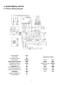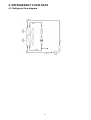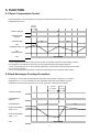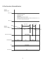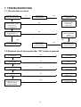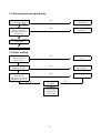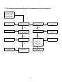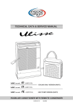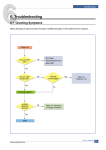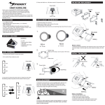
1
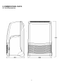
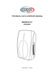
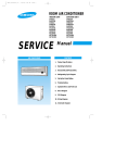
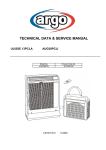
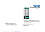
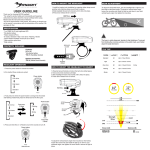
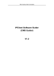
®
TECHNICAL DATA & SERVICE MANUAL
0.8180.367.0
05/2004
Page
3
3
4
1. SPECIFICATIONS
1-1 Unit Specifications
1-2 Major Component Specifications
6
6
2. DIMENSIONAL DATA
2-1 Unit Dimensions
7
7
3. ELECTRICAL DATA
3-1 Electric Wiring Diagram
8
8
4. REFRIGERANT FLOW DATA
4-1 Refrigerant Flow Diagram
5. FUNCTION
5-1 Room Temperature Control
5-2 Heat Exchanger Frosting Prevention
5-3 Dry Operation (Dehumidification)
9
9
9
10
11
11
6. PERFORMANCE DATA
6-1 Performance Chart
7. TROUBLESHOOTING
7-1 The unit does not work
7-2 Electrical circuit interrupted after "ON" button is pressed
7-3 Electrical circuit interrupted 3 minutes after "ON" button is pressed
7-4 Fan motor does not work while "ON" button is pressed
7-5 Fan works at one speed only
7-6 Poor cooling
7-7 Fan motor works normally but the compressor does not operate
2
12
12
12
13
13
14
14
15
1. SPECIFICATIONS
1-1 Unit Specifications
Power source
220 - 240 V ~ 50 Hz
Voltage rating
230 V
Performance
Capacity (1)
Efficiency (2)
Air flow rate (evaporator)
Air flow rate (condenser)
Moisture removal
Moisture removal
Moisture removal
Electrical ratings
Available voltage range
Power input
Running amperes
Power input
Running amperes
Power input
Running amperes
Compressor locked rotor
(1)
(2)
Package dimensions
Weight
DEHUMIDIFICATION
WITHOUT AIR EXHAUSTING TUBE
2100
2,75
310 / 260
290 / 240
1
-
-
W
W/W
m³/h
m³/h
l/h
l/24h
l/24h
Hi/Lo
Hi/Lo
(3)
(4)
V
W
A
W
A
W
A
A
(3)
(3)
(4)
(4)
Features
Controls/Temperature controls
Control unit
Timer
Fan speed
Air Filter
Operation sound Lp
(5)
Hi/Lo
Compressor
Refrigerant / Amount charged at shipment
Refrigerant control
Water tank capacity
Flexible exhaust tube
I.D.
extended length
Hole in the window
Electric cable with plug
length
Dimensions & Weight
Unit dimensions
COOLING
WITH AIR EXHAUSTING TUBE
dB(A)
g
liters
mm
m
mm
m
260
240
23
42
198 - 264
700
3,3
-
710
3,2
770
3,5
13
Microprocessor / I.C. Thermostat
Switches on the unit
2
1
Washable
55 / 51
51
Rotary (hermetic)
R410A / 470
Capillary tube
~ 3,3
115
1
138
2,9
Height
mm
Width
mm
Depth
mm
Height
mm
Width
mm
Depth
mm
Volume
m³
Net
kg
Shipping
kg
Data subject to change without notice
870
476
390
1110
577
483
0,31
32
41
Rating conditions
(1) Cooling
indoor air temperature:
27 °C d.b. , 19 °C w.b
(2) Cooling
indoor air temperature:
35 °C d.b. , 24 °C w.b
(3) Dehumidification
indoor air temperature:
27 °C d.b. , 21 °C w.b , 60% u.r.
(4) Dehumidification
indoor air temperature:
30 °C d.b. , 27 °C w.b , 80% u.r.
(5) Reference data: room size 100 m3 , reverberation time 0,5 s , distance 2 m
Operating limits
Indoor air temperature
maximum
Cooling
35 °C d.b. , 24 °C w.b
Dehumidification 35 °C d.b. , 28 °C w.b
3
minimum
15 °C d.b. , 12 °C w.b
10 °C d.b. , 6,5 °C w.b
1-2 Major Component Specifications
Controller PCB
Controls
(CE)
setting
differential
°C
°C
Starting delay time
Function selection and indicator lamp
Trasformer
capacity
primary
secondary
coil resistance primary (20°C)
coil resistance secondary (20°C)
Thermistor (coil sensor)
VA
V
V
Ω
Ω
(TH1)
°C
°C
open
close
Resistance
Ω
Thermistor (room sensor)
(TH2)
Resistance
Ω
Fan & Fan Motor
Type
Q'ty ……. Dia. and lenght
No. Of poles
Rpm
Power input (230 V)
(FM)
mm
Hi / Lo speed
W (Hi / Lo)
Coil resistance (25°C )
Ω
type
Safety devices
operating temp.
open
close
°C
°C
(C1)
µF
VAC
Run capacitor
Float microswitch
Contact rating
(MS)
up
down
RY2
Electronic
15 ± 1,5 ÷ 31 ± 2
0,9 ± 0,2
3 min ± 10 s
ON / OFF
COOLING / FAN
HIGH / LOW FAN
ALARM LAMP
1,5
220
10,5
2754 ± 10%
17,1 ± 10%
NTC
1±1
6±1
-20 °C: 5846 ± 5% ; 20 °C: 604 ± 5%
-10 °C: 3159 ± 5% ; 30 °C: 368 ± 5%
0 °C: 1766 ± 5% ; 40 °C: 230 ± 5%
10 °C: 1018 ± 5% ; 50 °C: 147 ± 5%
NTC
10 °C: 1018 ± 5% ; 30 °C: 368 ± 5%
15 °C: 781 ± 5% ; 35 °C: 290 ± 5%
20 °C: 604 ± 5% ; 40 °C: 230 ± 5%
25 °C: 470 ± 5% ; 50 °C: 147 ± 5%
M01974
Centrifugal blower
1…. Ø 170 / L 156
4
1275 / 1058 with flexible exhaust tube retracted
109 / 80
GREY-WHITE: 87,3 ÷ 101
WHITE-VIOLET: 36,2 ÷ 41,6
VIOLET-YELLOW: 22,8 ÷ 26,3
YELLOW-PINK: 22,8 ÷ 26,3
GREY-BROWN: 51,9 ÷ 59,6
Thermostat
150 ± 10
Automatic
3
450
CROUZET F83161.3
16(4) A - 250 VAC
open
close
Power relay (compressor)
Contact rating
Coil supply
Coil resistance (20 °C)
(PR)
VDC
Ω
OMRON G4F
20 A - 250 V
12
158 ± 10%
Compressor
Model
Nominal input (230 V)
Compressor oil
(CM)
Rotary (hermetic)
Coil resistance ( 20°C)
C-R
C-S
W
cc
Ω
Ω
5RS080EAA (R410A)
675
300
5,19 ± 7%
5,56 ± 7%
Data subject to change without notice
4
Safety devices
Type
Operating temperature
Operating amperes (25 °C)
(OLR)
open
close
open with
Run capacitor (compressor)
°C
°C
(C3)
µF
VAC
Condensate pump
Model
Nominal input (230 V)
Winding resistance
(PC)
Pump relay
Contact rating
Coil supply
Coil resistance (20 °C)
(RP)
W
Ω
Heat exchanger coil
Coils
Rows
Fin pitch
Face area
Heat exchanger coil
Coils
Rows
Fin pitch
Face area
20
450
291036
5
778 ± 8%
VAC
kΩ
H62S
5 A - 220 V
230
17,2 ± 10%
mm
m²
EVAPORATOR COIL
Aluminium fin - 3/8" Copper tube
4
1,8
0,042
mm
m²
5
EXTERNAL TYPE
MRA99137 - 9201
145 ± 5 °C
69 ± 9 °C
14 A in 6 ÷ 16 s
CONDENSER COIL
Aluminium fin - 7mm Copper tube
5
1,3
0,084
Data subject to change without notice
2. DIMENSIONAL DATA
2-1 Unit Dimensions
6
3. ELECTRICAL DATA
3-1 Electric Wiring Diagram
4,9
COMPRESSOR
CAPACITOR
ELECTRIC HEATER
FAN MOTOR
OVERLOAD PROTECTOR
ELECTRONIC CONTROL
COMPRESSOR RELAY
CONDENSATE PUMP
PUMP RELAY
DEHUMIDIFIER SWITCH
FLOAT MICROSWITCH
ELECTRIC HEATER RELAY
SENSOR
THERMOFUSE
SAFETY THERMOSTAT
PROGRAMMER
CM/C
Cx
RE
FMI/MV
OLR/K
CE
PR/RC
PC
RP
ID
MS
RR
TH1/S
TF
TS
P
32
Legend of colors
BLACK
BLUE
BROWN
GREEN/YELLOW
ORANGE
RED
WHITE
YELLOW
GREEN
PINK
7
BLK
BLU
BRN
GRN/YEL
ORG
RED
WHT
YEL
GRN
PNK
4. REFRIGERANT FLOW DATA
4-1 Refrigerant flow diagram
8
5. FUNCTION
5-1 Room Temperature Control
Room temperature control is obtained by cycling the compressor ON and OFF by means of room
temperature sensor TH1
minimum
3 minutes
ON/OFF SWITCH
ON
COMPRESSOR
SWITCH
ON
COMPRESSOR
ON
ON
SET
TEMPERATURE +1°C
SET
TEMPERATURE
SET SPEED
FAN
NOTES
1. If the compressor is turned off, the control circuit sets an automatic minimum 3 minutes delay to protect
the compressor from stalling out when trying to start against the high side refrigerant pressure.
2. If the room temperature is 1°C above the set temperature, the compressor starts working if this has been
OFF for at least 3 minutes.
3. If the room temperature is the same or under the set temperature the compressor stops working.
5-2 Heat Exchanger Frosting Prevention
The electronic control stops automatically the compressor each time the coil sensor TH1 reaches a
temperature of 1 °C for 8÷10 minutes long, the compressor starts again automatically when the
temperature of heat exchanger reaches 8 °C. the fan goes "ON" working at the set speed.
minimum
minimum
10 minutes
3 minutes
ON/OFF SWITCH
ON
COMPRESSOR
SWITCH
ON
COMPRESSOR
ON
ON
HEAT EXCHANGER
TEMP. = 8°C
HEAT EXCHANGER
TEMP. = 1°C
SET SPEED
FAN
9
5-3 Dry Operation (Dehumidification)
AMBIENT
TEMPERATURE
MAX. 35 °C
- PUSH BUTTON COOL/DRY.
- COMPRESSOR "ON".
- LOW SPEED.
- AMBIENT THERMOSTOR BY-PASSED.
- COMPRESSOR OFF AFTER 10 MIN. WITH AMBIENT TEMPERATURE AT 10 °C.
- UNIT WITHOUT AIR RXHAUSTING TUBE.
MIN. 10 °C
MIN. 3 MIN.
MIN. 10 MIN.
AMBIENT
TEMPERATURE
10 °C ±1 °C
DRY POSITION
BUTTON COOL/DRY
COMPRESSOR
ON
OFF
LOW SPEED
FAN
ON
LED YELLOW
10
ON
OFF
6. PERFORMANCE DATA
6-1 Performance Chart
4,9
32
Operating characteristics with relative humidity around 50%
Operating current (A)
5,00
4,50
4,00
3,50
3,00
2,50
18
20
22
24
26
28
30
Room temperature (°C)
11
32
34
36
7. TROUBLESHOOTING
7-1 The unit does not work
Check the voltage. Are
there 198 ÷ 264 volts ?
YES
NO
Check the unit
electrical cable
Check if programmer
contact is closed (black brown cables).
(IF INSTALLED)
YES
NO
Check if there is supplied
voltage between 1-2
the electric control (CE)
NO
YES
If it is impossible to
close the contact,
replace the
programmer.
Check if tank micro switch contacts are
closed.
(1 - 2 MT contacts)
NO
YES
Replace the electronic
control (CE)
Check the electrical
supply line
Check if the pilot
lamp is burnt.
Eventually replace it
NO
Is the flickering alarm
lamp on the control
panel not visible ?
7-2 Electrical circuit interrupted after "ON" button is pressed
Check the unit hardness
Is it insulated ?
YES
NO
Insulate the short
circuit cable
Check if the fan motor is
working (FMI)
YES
NO
Replace the fan motor
(FMI)
Check the electronic
control (CE)
YES
NO
Replace the electronic
control (CE)
Check the leds printed
circuit.
NO
NO
Replace the leds
printed circuit.
Check the motor
YES
Replace the
programmer (P)
programmer (P). Is it
short circuited?
(IF INSTALLED)
12
7-3 Electric circuit interrupted 3 minutes after "ON" button is pressed
COOLING
OPERATION
Check if compressor relay
NO
Rebuild the
connections.
YES
Replace the
compressor relay
connections are
insulated.
YES
Check if compressor relay
works.
Is it in short circuit ?
(PR)
NO
Check if compressor
winding are short
circuited.
YES
Replace the
compressor(CM)
7-4 Fan motor does not work while "ON" button is pressed
Disconnect the unit from line. Check if the fan motor is well
fitted and if the blades can rotate
YES
NO
NO
Check hardness and
various continuities
YES
Fit the fan motor
properly or replace
it
Remove obstruction
or replace fan motor
assembly
Check the capacitor
capacity (C)
YES
NO
Replace the capacitor
INTERRUPTED
Replace the fan motor
assembly
Check the fan motor
windings (FMI).
YES
Replace the electronic
control (CE)
13
7-5 Fan works at one speed only
Check electrical conections. Is there continuity ?
YES
NO
Fit electrical connec tions properly
Check power supply
between 1-7(high) or
1-8(low) electronic control
contacts (CE)
YES
NO
Replace the electronic
control (CE)
Is the unit cooling capacity
suitable for the room
thermal loads ?
YES
NO
Suggest a more powerful unit
Are both air filters and heat
exchanger cleaned ?
YES
NO
Clean filters and / or
heat exchanger
Check if Difference between room air
temperature and outlet air
delivered is up to 10 °C
YES
The unit works properly
Check fan motor winding
values (MV)
YES
Replace fan motor (MV)
7-6 Poor cooling
NO
Low
gas charge
Proceed with
normal operations
foreseen for the
above points
14
NO
7-7 Fan motor works normally but the compressor does not operate
Check hardness
and continuity. Is the
relay compressor
coil (PR white cable)
power supplied ?
YES
Replace the relay
(PR)
NO
Check if relay
contects are closed
YES
YES
Replace klixon (ORL)
YES
NO
Check compressor
klixon contacts (ORL)
Are they open ?
Is room tempera ture over 15 °C ?
NO
Adjust thermostat
position
NO
The unit cannot
operate below
15 °C
NO
Replace the
sensor (TH2)
YES
Check the capaci tor capacity (C)
Check the sensor
continuity (TH2)
through 9-10
electronic control
(CE) terminal
blocks
YES
YES
Replace the
compressor
NO
YES
NO
Replace the
capacitor (C)
Is the thermostat in
the right position ?
Check the com pressor winding
continuity
Check electronic
control (CE)
15
Via Varese, 90 - 21013 Gallarate - Va - Italy
Tel. +39 0331 755111 - Fax +39 0331 776240
www.argoclima.it