1
Service / Workshop Manu al
Electrical Information
Hosted and optimised by www.TheTVRSite.com
Electrical Information
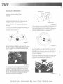
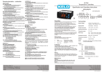
Indicator Cancellation Disk
- Set Up.
1. Before attempting to reset the indicator cancellation
mechanism you must firstly ensure the wheels and
steering arc straight - have been tracked.
2. Tum ignitalion on. - As described in the Owners
Handbook.
3. To activate the indicator cancellation mechanism you
must Simultaneously press (A) the 3 steering wheel buttons (shown in the diagram 1).
(diagram 3)
Once it has gone oul note the angle of the steering wheel
before returning 10 the central/striaght position.
You can then measure the displacement on the opposite
lock by turning in the opposite direction until the indiactor light on Ih.is side goes oul. (diagram 4 )
A
..
~
diagram 1
You are then in the setup mode. The main beam will
come on and stay on whilst set in this mode. The indicators will also light up if the indiactor sensor (which is
shown in diagram 2 ) is covered by Ihe turning of the
steering wheel.
( diagram 4)
5. If the two angles <Ire not the same (left lock and right
lock) the indiaetor cancellation disk can be adjusted by
turning the canc:ellation disk on the steeri ng shaft, (as
indicated on the- diadram) to ensure the cancellation of
the indicators is the same for both lefthand turning circle <lnd the righthand.
6. Once the adjustment has been done, to exit the cancellation mode you h<lve been working in just switch off
the ignition as indicated below. (diagram 5 )
(diagram 2)
4. To work out Ihe angle of displacement for each turning circle (Anti-Clockwise ~ Right turning circle and
Clockwise:: Left turning circle) Tum the wheel in the
direction desired until the indiactor arrow on that side
goes out. This means th<lt the sensor on the stl..'ering column has been coven.od by the cancellation disk,thus
breaking the connection, (see diagram 3 )
(diagram 5)
Hosted and optimised by www.TheTVRSite.com
(
CERBERA SERVICErWORKSH
Operation of the Alarm
The Alarm System installed in the Cerbera has been
designed to provide optimum protection at all times.
The System uses a Rolling Code Radio key which never
uses the same code twice and is therefore code grabber
proof.
Alarming
1. Assuring both door 5 are shut. (The control system is
told the doors are dosed by receiving a 5 volt and
greater output from the door pin imports.)
2. Switch alarm into armed mode - (As described in the
Owners Handbook.)
(Door control alarm import will he equal to or g reater
than 5 volts.)
P lVIANUAL
-Dog Mode - Locking the doors without
arming the alarm.
1. Set window height before leaving the car.
2. Open a door.
3. Press and hold status led button far mote than 5
seconds, this will result in the led flashing rapidly to
indicate you arE~ in the dog mode.
4. Once the led is flashing rapidly the d oors can be shut.
They will then be locked. The boot will also lock.
5. To overide this mode from outside the car - arm and
then disarm the alarm.
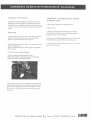
3. This will result in Auto Closure :A) The windows will automatically close.
D) The status LED/ Lock button on the centra.l dash
panel (sce diagram) will flash rapidly.
N.B. If the door is open when the alarm is activated the
alarm system will activate but the door control will noi,
thus not activating the Auto Closure sequence. To lock
the doors you must disarm the alarm and then rearm
the alarm.
/
Hosted and optimised by www.TheTVRSite.com
Service / Workshop Manual
Revision 3 Connector Listings
/
Hosted and optimised by www.TheTVRSite.com
·
.
t;"~"
.:'
.
contents
IJ
mmm
Front Harness Connection.s
- Ill
Front Harness Spliced Join ts
-,
Front Harness Multiway Connections
······································m
···········-··· ................... .
Rear Harness Connections
Rear Harness MlIltiway Connections
Rear Harness Spliced Joints
Fuseboard
/
)
Hosted and optimised by www.TheTVRSite.com
CERBERA SERVICEI-WORKSH
PMANUAL
TVR Cerbera Electrical Connections - Revi s ion 3
Modificationslrequirements:
This revision incorporales changes in the connector manufacture/supplier:
The AMP "Duomate" range of w ire to wire connectors have now been replaced. The new range that
replaces these components are supplied by rrr Cannon and are known as the "Trident" range.
The following wire lists have been created to enable these connectors to be used and to
allow for some minor modifications to power supply distribution and fuhlre
developments within ECU's.
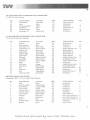
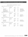
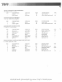
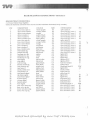
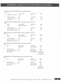
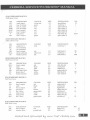
Front Harness Connectors - Revi s ion 3
U') BONNET SW ITCH,
1:>. 2 way Trident Snap Together
P[N
I
2·
DESCRIPTION
e<Uth
COLOUR
black
bonnet s ignal
blue/black
SIZE
O.S
O.S
DESCRll'TION
COLOUR
SIZE
ignition
brakes signal
green
DESTINATION
earth point
multiway 1
P[N
21
U2,A , )"'B)BRAKE LI G HT SWITCH,
2 x 6.3mm spades &: covers
PL'I
green/purple
0.5
0.5
DESTINATION
spliced joint 3
multiway 2
PIN
10
U3) CIGARETTE LIG HTER,
1 x 3 way Trident Snap Together
PIN
2
3
DESCRll'TION
COLOUR
battery
earth
illumination
,od
SlZE
DESTINATION
1.0
0.5
0.5
spliced joint 7
earth point
spliced joint 9B
COLOUR
black/ white
black/ red
SIZE
0.5
DESTINATION
P[N
18
19
green/black
green
0.5
0.5
0.5
0.5
0.5
multiway 1
multiway 1
tnultiway 1
spliced joint 1
spliced joint 7
earth point
spliced joint 9A
black
red /whi te
PIN
U4) COLUMN POD HARNESS,
1 x 12 way Trident Snap Together
PIN
1
2
3
4
S
6
7
DESCRll'TION
s tart signal
stop signal
fuel signal
ignition
battery
earth
illumination
red
black
red /white
O.S
/
U5) COURTESY LAMPS' SUB - HARNESS:
1 x 3 way Trident Snap Together
PIN
1
2
3
DESCRll'TION
COLOUR
battery
ea rth
lamp control
,.d
black
purple/red
20
SlZE
0.5
0.5
0.5
DESTINATION
spl iced joint 7
earth point
multi way 2
Hosted and optimised by www.TheTVRSite.com
PIN
11
..,.-
•
•
',1 ..
• ~
i,
.
'.
')
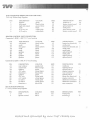
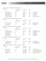
U6) DASH SWITCHES' INTERFACE UN IT CONNECfOR:
1 x M1C rv 9 way housing
PIN
Al
A2
AS
81
82
55
DESCRIPTION
illumination
earth
fog lamps signal
headlamps
sideJamp signal
fog lamp w/I
COLOUR
red/white
black
yellow
blue
white
yellow/red
SIZE
05
05
05
05
05
05
DESTINATION
spliced joint 9A
earth point
multiway 1
spliced joint 12
multiway 1
multiway 1
PIN
15
16
23
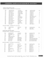
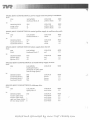
U7) DASHBOARD INSTRUMENT POD CONNEcrOR:
1 x 24 way Trident Snap Together
PIN
1
2
3
,
S
6
7
8
9
10
11
12
13
14
IS
16
17
18
DESCRlP110N
ignition
speedo signal
main beam w / 1
oil pressure w / 1
indicate left
illumination
indicate right
tacho input
EFl lamp
handbrake
alternator
..,.th
shift lamp
brake nuid
ice 1
inertia sw
ice 2
drivers seat belt
COLOUR
SIZE
ST""n
05
0.5
05
05
05
05
05
05
0.5
05
05
05
05
05
05
05
05
05
S'ey
blue/white
brown/white
green/red
red/white
green/white
white/black
light gm/black
black/yellow
brown/yellow
black
orange
black/ white
white/pink
bl,ok I ST"""
white/green
grey/black
DESTINATION
spliced joint 1
multiway 1
multiway 1
cngine harness conn.
spliced joint 11
spliced joint 9A
spliced joint 10
engine harness
engine harness conn.
handbrake switch
cngine harness conn.
earth point
engine harness conn.
brake fluid switch
heater ECU conn 2
multiway 1
heater ECU conn 2
multiway 2
PIN
26
,
25
I'
12
S
11
B7
24
B8
3
,
DRIVER'S DOOR CONNEcrOR:
Connector 1: UB) 1 x 12 W.1Y Trident Snap Together
PIN
1
2
3
4
5
6
7
8
9
IO
11
12
DESCRIPTION
earth
door pin swi tch
inner release
outer release
window drive I
window drive 2
mirror heater
common.
mirror 1
mirror 2
position signal
ignition
COLOUR
black
white/purple
orange/white
orange
yellow/black
yellow / green
blue/orange
black/red
light green
slate
blue/yellow
g""'"
SIZE
05
0.5
05
05
I.S
' .5
0.5
0.5
0.5
0.5
0.5
0.5
DESTINATION
PIN
earth point
mllltiway 1
I
multiway I
2
multiway 1
3
multiway 1
4
mllltiway 1
5
spliced joint 14
pass. door connector 2 8
pass. door connector 2 9
pass. door connector 2 IO
multiway 1
6
spliced joint 1
l
Hosted and optimised by www.TheTVRSite.com
CERBERA SERVICE/"WORKSH
PMANUAL
~
~
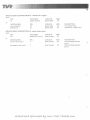
Connector 2: (J9) 1 x 3 way Trident Snap Together
1
2
3
illumination
speaker +
speaker -
red/white
s late
slate/black
0.5
0.5
0.5
spliced joint 9B
radio connector (brown) 3
radio connector (brown) 4.
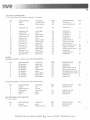
UID) ENGINE HARNESS CONNECfOR:
1 x 19 way Grate and Hartmann ( 4power . 15 signal)
PIN
1
2
3
4
5
6
7
8
9
10
11
12
13
14
15
16
17
18
19
DESCRIPTION
COLOUR
fuel pump drive
radiator drive 2
lambda heat
oil pressure
alternator w /1
yeIJow
battery ECU
ign. injectors
starter solenoid
ign. coil odd
ign. coil even
shift lamp
Efl fault lamp
purge valve drive
tacho
radiator drive 1
ignition ecu
A/Cdutch
A/Cackn.
A/C req.
green/pink
yellow Iblack
brown/while
brovm/ yellow
coo
StZE
0.5
0.5
0.5
0.5
purple/black
0.5
0.5
1.0
3.0
1.0
1.0
0.5
0.5
0.5
white/black
0.5
green/pink
0.5
0.5
green
white/red
green
green
orange
It. green/black
gyeen
white/green
white/black
white/pink
DESTINATION
multi way 2
multiway 2
multi way 2
dashboard connector
dashboard connector
spliced joint 8
spliced joint 6
muttiway 3
4
11
9
spLiced joint 4
0.5
0.5
spliced joint 4.
dashboard connector
dashboard connector
multiway 2
dashboard
spliced joint 13
spliced joint 6
heater control conn 2
heater control conn 2
nose connector
SIZE
0.5
0.5
earth point
dashboard connector
0.5
PIN
2
J6
17
13
9
19
8
65
A6
15
Ull:A, Jll:B) HAND BRAKE SWITCH:
2 x 6.3mm spades & covers
PrN
DESCRIPTION
COLOUR
earth
black
black/yellow
h/brake sw.
DESTINATION
PIN
10
U12) HEATER BOX (HEATED AIR),
1 x 6 way Trident Snap Together
PIN
1
2
3
4
DESCRIPTION
COLOUR
ignition
hot speed
left side-repeat
green
black/yellow
green/red
black
eacth
StZE
2.0
1.5
0.5
0.5
DESTINATION
multiway 2
heater control conn 1
spliced joint 11
earth point
Hosted and optimised by www.TheTVRSite.com
PIN
4
A7
~
i'"I
013) HEATER BOX (FRESH AIR AND AIR CON.):
1 x 6 way Trident Snap Together
PIN
1
2
3
4
5
6
DESCRlPTION
COLOUR
ignition
Ween
black/white
green/white
black
white/pink
white/pink
cold speed
right side-repeat
earth
Ale reg. out
Ale reg. in
StzE
2.0
1.5
0.5
0.5
0.5
0.5
DESTINATION
PIN
multiway 2
heater control corm 1
spliced joint 10
earth point
nose harness (ann.
hea ter control (ann 2
24
A3
12
B2
HEATER CONTROL UNIT CONNECTOR:
Connector1: 014) 1 x MlC TV 17 way housing
PIN
A3
A4
A7
A8
A9
B2
B3
85
B9
DESCRIPTION
cold speed
eructh
hot speed
earth
COLOUR
black/white
black
black/yellow
black
black
earth
ignition
earth
gceen
black
ignition
ignition
ween
Connector 2: 015) 1 x MJC
ween
StzE
1.5
2.0
1.5
2.0
0.5
0.5
0.5
0.5
0.5
DESTINATION
heater box (fresh air)
earth point
heater box (heated air)
earth point
PIN
2
'1-'
2
earth point
spliced joint 5
earth point
spliced joint 5
spliced joint 5
rv 17 way housing
PIN
DESCRIPTION
COLOUR
Al
A3
A4
A6
A9
B1
62
85
B7
B8
69
rear window
mirror heat
ignition
A/C ackn.
thermistor ·
ignition
A/C req.
A/C dutch
ice LED 1
ice LED 2
thermistor +
purple/red
blue/orange
ween
white/black
black/slate
ween
white/pink
white/green
white/pink
white/green
black/red
StzE
0.5
05
05
05
0.5
0.5
05
05
05
0.5
0.5
DESTINATION
multiway
spliced joint 14
spliced joint 5
engine connector
nose connector
spliced joint 5
heater box (fresh air)
engine connector
dashboard connector
dashboard connector
nose connector
PIN
18
16
6
17
15
17
14
016} IGNITION SW1TCH:
1 x 2 way Trident Snap Together
PlN
DESCRIPTION
1
2
earth
ignition control
COLOUR
black
black
StzE
05
0.5
DESTINATION
earth point
multiway 2
.,.
PIN
15
)
Hosted and optimised by www.TheTVRSite.com
..
CERBERA SERVICEIWORKSH
PNlANUAL
.of
(17) INNER LOCK BtrITON + DOOR STATUS LED:
1 x 6 way Trident Snap Together
PrN
I
2
3
4
DESCRIPTION
earth
lock signal
battery
led drive
COLOUR
black
black/white
"d
black/red
SIZE
DESTINATION
earth point
rnuJtiway I
spliced joint 7
multiway 1
PIN
PrN
0.5
0.5
0.5
0.5
1.5
1.5
0.5
0.5
0.5
0.5
0.5
0.5
DESTINATION
earth point
multiway 1
multiway I
multi way 1
multiway 1
multiway I
spliced joint 14
driver's door conn 2
driver's door conn 2
driver's door conn 2
multiway 1
spliced joint 1
0.5
0.5
0.5
spliced joint 9B
radio connector (brown) 5
radio connector (brown) 6
0.5
0.5
0.5
0.5
13
14
PASSENGER DOOR CONNECTORS:·
Connector 1: (J1B) 1 x 12 way Trident Snap Together
PrN
I
2
3
4
5
6
7
8
9
10
11
12
DESCRIPTION
earth
door pin switch
iimer release
outer release
window drive 1
window drive 2
mirror heater
common.
mirror 1
mirror 2
position signal
ignition
COLOUR
black
white/purple
orange/white
orange
red/black
red/green
blue/orange
black/red
light green
slate
blue/red
green
SIZE
7
8
9
10
11
8
9
10
12
Connector 2: (19)
1 x 3 way Trident Snap Together
1
illwnination
red/white
2
3
speaker +
green
green/black
speaker -
020) LOW BRAKE FLUID SWITCH,
2 x Frama tome brake servo terminals and seals (housing fitted afterwards)
PrN
DESCRIPTION
earth
low fluid signal
COLOUR
black
black/white
SIZE
0.5
0.5
DESTINATION
earth point
dashboard cOlU1ector
Hosted and optimised by www.TheTVRSite.com
PIN
14
{g',
r
~.~.-
Fe." -
;-,
U21) NOSE CONNECTOR:
1 )(
19 way Grate and Harlmann (4power - IS signal)
DESCRIPTION
PIN
I
2
3
4
5
6
7
8
9
10
11
12
13
14
15
16
17
18
19
horns
washers
COLOUR
purple/white
blue/yellow
sidelamps r/ h
sidelamps I/h
engine fan 1
main beam r/ h
main beam l /h
engine fan 2
indicator r/ h
A/C req. in
indicator IIh
thermistor +
A/C rcq. out
Ulermistor dip beam r/h
A/C fan control
dip beam I/ h
SIZE
1.0
PIN
0.5
DESTINATION
multiway 3
wiper control unit
red/white
0.5
multiway 3
4
red/white
pink
blue/while
blue/whi te
pink
green/ white
white/ pink
0.5
3.0
1.S
1.5
3.0
0.5
0.5
0.5
0.5
0.5
0.5
1.0
0.5
1.0
multiway 3
multiway 3
muJtiway 3
multiway 3
multiway 3
spliced joint 10
heater box (cold)
spliced joint 11
heater control conn 2
engine connector
heater control conn 2
multiway 3
spliced joint 13
multiway 3
6
green / red
black/ red
white/ pink
black/slate
blue /red
green/pink
blue/red
2
A9
7
1
3
10
6
89
19
A9
17
19
RADIO:
Connector 1: U22) 1 x Pioneer 8 way ISO block. BROWN
PIN
1
2
3
DESCRIPTION
RR speaker +
RR speakerFR speaker +
FR speaker FL speaker +
FL speakerRL speaker +
RL speaker-
4
5
6
7
8
COLOUR
slate/red
black/slate
slate
slate/black
green
green/black
green/red
black/green
SIZE
0.5
0.5
0.5
0.5
0.5
0.5
0.5
0.5
multiway 2
7
multiway 2
8
drivers door conn 2
2
drivers door conn 2
3
passengers door conn 2 2
passengers door conn 2 3
multiway 2
5
multiway 2
6
DESTINATION
PIN
SIZE
0.5
spliced joint 7
0.5
0.5
0.5
spliced joint 98
spliced joint 1
earth point
Connecto r 2: U23) 1 x Pioneer 8 way ISO block. BLACK
PIN
DE5CRIPTlON
COLOUR
4
battery
antenna power
illumination
ignition
earth
red
5
6
7
8
PIN
unu.ro
red /white
g<een
black
~
U24) REVERSE LIGHT SWITCH:
1x2
DESTINATION
way sealed
PIN
A
B
DESCRIPTION
COLOUR
ignition
reverse signal
green
It green/brown
SIZE
0.5
0.5
DESTINATION
spliced joint 3
multiway
Hosted and optimised by www.TheTVRSite.com
PIN
"
CERBERA SERVlCEIWORKSH
PMANUAL
(125) STEEIUNG WH EEL CONTROL UNIT CONNECTOR:
1 x MIC rv 17 way housing
PIN
A2
A6
A7
A8
A9
61
62
63
B4
DESCRIPTION
head lamp input
w iper2 s ignal
main beam s ig.
dip beam signal
turn left s ig nal
ignition
horn
hazard s ignal
battery
B5
66
earth
BB
wash signal
turn right s ignal
B9
wiperl signal
COLOUR
SIZE
blue
0.5
0.5
0.5
0.5
0.5
0.5
0.5
0.5
0.5
0.5
0.5
0.5
0.5
,ed/green
blue/while
blue/ red
green/red
green
purple/black
brown/black
,ed
black
blue /green
blue/yellow
green/white
DESTINATION
spliced joint 12
wiper control unit
multiway 1
multiway 1
mulLiway 1
spliced joint 2
multiway 1
multi way 1
s pliced joint 8
earth point
wiper control unit
w iper control unit
multiway 1
PIN
61
28
27
29
32
31
B2
B9
30
WINDOW SWITCHES CONNECTOR
Driver's window switch: (26)
1 x 6 way Trident Snap Together
PIN
I
DESCRIPTION
earth
2
3
win. up signal
win. dO\'1/Tl signal
4
illumination
earth
5
6
earth
027) Passenge,r's window switch:
I x 6 way Trident Snap Together
PIN
I
2
3
4
5
6
COLOUR
SIZE
red/ white
black
black
0.5
0.5
0.5
0.5
0.5
0.5
SIZE
black
yeUow Iblack
yellow I green
DESCRIJ'TION
COLOUR
earth
win. up signal
win. down signa.!
illumination
earth
black
red/green
red / white
black
eMIh
black
red/black
0.5
0.5
0.5
0.5
0.5
0.5
DESTINATION
PIN
earth point
multiway 1
multiway 1
splice joint 98
earth point
earU, point
DESTINATION
earth point
multiway 1
multiway 1
splice joint 98
earth point
earth point
36
35
PIN
34
33
028)WIPER CONTROL UN IT CONNECTOR:
1 x MlC IV 17 way housing
PIN
DFSCRIPTION
A2
park switch
speed 1 drive
ignition
speed 2 drive
washer drive
wiper2 signal
w iperl signal
washer signal
A3
A4
A6
A9
61
B2
8.
COLOUR
brown /green
blue/green
g.een
red/green
b lue/yellow
red/green
blue/green
blue/yellow
SIZE
1.5
1.5
1.5
1.5
0.5
0.5
0.5
0.5
DESTINATION
PIN
wiper motor
2
wiper motor
3
spliced jomt 2
wiper molar
3
nose connector
2
steering wheel control A6
steering ~... heel control B6
steering wheel control BB
Hosted and optimised by www.TheTVRSite.com
029) WIPER MOTOR CONNECfOR
1 x 5 way dedicated Lucas housing
PIN
1
2
3
4
5
DESCRIPTION
earth
park switch
speed 2 drive
ignition
speed 1 drive
COLOUR
black
brown / green
red / green
g<een
blue/green
SIZE
1.5
1.5
1.5
1.5
1.5
DESTINATION
PIN
earth point
wiper control unit
wiper control unit
spliced joint 2
wiper control unit
A2
A6
A3
j'
,I
Hosted and optimised by www.TheTVRSite.com
I
CERBERA SERVICEIWORKSHQP MANUAL
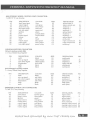
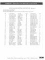
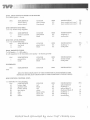
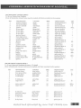
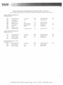
FRONT HARNESS SPLICED JOINTS - Revision 3
SPLICED JOINT CONNECTION 1: ignition suppl y
from:
PL'I
LOCATION
multiway 2
13
COLOUR
green
SIZE
1.0
to:
DESTINATION
column pod
dash. instrument pod
driver's door conn. 1
passenger's door conn. 1
radio black ISO B way
SPLICED JOINT CONNECTION
PIN
COLOUR
4
8'een
green
8'cen
8'=
g.-ecn
1
12
12
7
2: ignition supply
SIZE
0.5
0.5
0.5
0.5
0.5
DESCRIPTION
fuel gauge power
dashboard power
mirror control power
mirror control power
radio power
from:
PIN
J
LOCATION
multiway 2
COLOUR
g reen
SIZE
I.S
PIN
COLOUR
A4
8'''''"
g,een
green
SIZE
LS
10:
DESTINATION
wiper ECV
wiper motor
s leering wheel ECU
4
HI
1.5
0.5
DESCRJPTION
wiper power
park switch power
ECU power
SPLICED JOINT CONNECTION 3: ignition supply
from:
PIN
LOCATION
COLOUR
18
multiway 2
8'een
DESTINATION
brake switch
PIN
COLOUR
reverse switch
A
green
g.-ecn
SIZE
1.0
to:
SIZE
0.5
0.5
DESCRJPTION
brake lamp power
reverse lamp power
SPLICED JOINT CONNECTION 4 ignit'ion supply
from:
PfN
LOCATION
COLOUR
12
multiway 2
8""'n
SIZE
1.5
to:
DESTINATION
PIN
COLOUR
engine harness
engine harness
9
8""'n
8'een
10
SIZE
1.0
1.0
DESCRJPTION
coil odd power
coil even power
Hosted and optimised by www.TheTVRSite.com
•
.;.0.
J
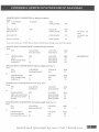
SPLICED JOINT CONNECTION 5 ignition supply
from:
PIN
LOCATION
multiway 2
COLOUR
green
SIZE
21
DESTINATION
PIN
COLOUR
SIZE
heater ECV conn 1
heater ECV cann 1
heater ECU conn 1
heater ECV conn 2
hea ter ECV conn 2
B9
B5
B2
g,een
green
green
STeen
green
1.0
to:
A4
BI
0.5
0.5
0.5
0.5
0.5
DESCRIPTION
pcb power
fan suppress
flap power
ACpowcr
mirror + window heat
SPLICED JOINT CONNECTION 6 ignition supply
from:
PIN
LOCATION
COLOUR
9
multiway 2
green
DESTINATION
engine harness
engine harness
PIN
COLOUR
7
16
green
green
SIZE
1.5
1
to:
SIZE
1.0
0.5
DESCRIPTION
injector power
ECV power
SPLICED JOINT CONNECTION 7 hi'lttery supply
from:
PIN
14
LOCATION
multiway 2
COLOUR
red
SIZE
1.5
to:
DESTINATION
radio black ISO 8 way
inner lock button
column pod
courtesy lamp
cigarette tigh ter
PIN
COLOUR
4
3
red
red
5
'00
I
1
,00
<cd
SIZE
0.5
0.5
0.5
0.5
1.0
DESCRIPTION
radio memory backup
LED power
clock power
lamp power
lig hter power
SPLlC£D JOINT CONNECTION 8 battery supply
from:
LOCATION
multiway 2
COLOUR
",d
SIZE
20
DESTINATION
PIN
B4
6
COLOUR
,ed
,ed
SIZE
steering wheel ECV
PIN
1.0
to:
cngine harness
0.5
0.5
DESCRIPTION
ECU suppression
ECU backup power
SPLICED JOINT CONNECTION 9A instrument illumination
from:
PIN
15
LOCATION
multiway 3
COLOUR
red/white
SIZE
PIN
COLOUR
red/white
red/white
red/white
red/white
SIZE
1.0
to:
DESTINATION
column pod
dash switches
dashboard
spliced joint 98
7
Al
6
0.5
0.5
0.5
05
DESCRlPTION
instrument illumination
lamp switch illumination
instrument ill umination
illumination power
,
Hosted and optimised by www.TheTVRSite.com
)
"
,
CERBERA SERVl'CEIWDRKSH
,
PlWANUAL
-,
SPLICED JOINT CONNECTION 98 instrumen t il lumination
from:
PIN
LOCATION
COLOUR
s pliced joint 9A
red /white
SIZE
0.5
10;
DESTINATION
cigarette light
driver's door conn 2
passenger's door caM 2
radio black 8 way ISO
driver window switch
pass. window switch
SPLICED JOINT CONNECTION
PIN
3
1
1
6
4
COLOUR
red /whi te
red/white
red /white
red/white
red/white
4
red/white
10 right hand indicator
SIZE
0.5
0.5
0.5
0.5
0.5
0.5
DESCRIPTION
lighter illumination
release illumination
release illumination
radio illumination
switch illumination
switch illumination
from:
PIN
COLOUR
14
LOCATION
multiway 3
green/white
DESTINATION
PIN
COLOUR
11
3
7
green/wrute
green / w hi le
green/white
SIZE
1.0
to:
nose connector
heater box cold
dashboard
SPLICED JOINT CONNECTION 11 left hand indicator
from:
PIN
LOCATION
16
multiway 3
to:
DESTINATIO
PIN
nose connector
13
heater box hot
3
dashboard
5
SIZE
0.5
0.5
0.5
COLOUR
SIZE
green/red
1.0
COLOUR
green/red
green/red
green/red
SIZE
SPLICED JOINT CONNECTION 12 - head lamp signal
from:
PIN
LOCATION
COLOUR
dash switches
blue
B1
0.5
0.5
0,5
DESCRIPTION
rh front indicator
rh side repeater
indicator warning lamp
DESCRIPTION
lh front indicator
lh side repeater
indicator warning lamp
SIZE
05
to:
DESTINATION
steering wheel ECU
multiway 1
PIN
A2
17
COLOUR
blue
blue
SIZE
05
0.5
DESCRlPTlON
head lamps on signal
head lamps on signal
Hosted and optimised by www.TheTVRSite.com
SPLICED JOINT CONNECTION
from:
PIN
15
to:
DESTINATION
nose connector
multiway 2
13 . radiator fan 1 signal
SPLICED JOINT CONNECTION
from:
PIN
A3
to:
DESTINATION
driver's door conn 1
14 . nurror heater drive
passenger's door conn 1
LOCATION
engine harness
COLOUR
green/pink.
SIZE
0.5
PIN
18
COLOUR
green/pink.
22
green/pink
SIZE
0.5
0.5
LOCATION
heater ECU conn 2
COLOUR
blue/orange
SIZE
0.5
PIN
7
COLOUR
blue/orange
SIZE
0.5
7
blue/orange
0.5
DESCRIPTION
AC control of fan
radiator fan 1 relay drive
DESCRIPTION
mirror heating element
power
mirror heating element
power
.,
;
.
Hosted and optimised by www.TheTVRSite.com
,
CERBERA SERV'ICE/1NORKSH
PMANUAL
FRONT HARNESS MULTI WAY CONNECTIONS - Revision 3
030) MULTI WAY CONNECTOR 1:
1 x 36 way Trident Snap Together
(Note: all identically coloured wires must be marked with their associated cavity number)
11
DESCRIPTION
driver door pin S \" .
driver inner release
driver outer release
driver window 1
driver window 2
driver window pas
pass. door pin sw.
pass. inner release
pass. outer release
pass. window 1
pass. window 2
12
pass. window pos.
13
lock button sig
locked LED sig
fog lamp sw. sig
sidelamp sw. sig
headlamp sw. sig
start signal
stop signal
fuel level sig
bonnet switch sig
rear window sig
rear fog w/I
inertia switch w / 1
main beam w/I
rood speed signal
dip beam signal
main beam s ignal
lh turn signal
rh tum signal
hazard signal
horn signal
pass. win. down sig
pass. win. up sig
driver win.down sig
driver win. up sig
PIN
1
2
3
4
5
6
7
8
9
10
14
15
16
17
18
19
20
21
22
23
24
25
26
27
28
29
30
31
32
33
34
35
36
COLOUR
SIZE
DESTINATION
white/purple
orange/white
0.5
0.5
0.5
1.5
1.5
0.5
0.5
0.5
0.5
1.5
1.5
0.5
0.5
0.5
0.5
0.5
0.5
0.5
0.5
0.5
0.5
0.5
0.5
0.5
0.5
0.5
0.5
0.5
0.5
0.5
0.5
0.5
0.5
0.5
0.5
0.5
drivers door conn 1
orange
yellow /black
yel low/green
blue/yellow
white/purple
orange/white
orange
red/black
red/ green
blue/ red.
black/white
black/red
yellow
white
blue
black/white
black/red
green/black
blue/ black
purple/red
yellow/red
black/green
blue/white
slate
blue/red
blue/white
green/red
green/white
brown/black
purple/black
red /green
red/black
yellow I green
yellow /black
drivers door conn I
drivers door conn 1
drivers door conn 1
drivers door conn 1
driver's door cann 1
passenger door conn 1
passenger door conn 1
passenger door COM 1
passenger door (ann 1
passenger door cann I
passenger door conn 1
inner lock button
inner lock button
dash switches unit
dash switch es unit
splice joint 12
column pod unit
column pod unit
column pod unit
bonnet switch
heater ECU conn. 2
dash switches unit
dashboard
dashboard
dashboard connector
s teering wheel unit
s teering wheel unit
steering wheel unit
steering wheel unit
steering wheel unit
s teering wheel unit
pass. window switches
pass. window switches
drivers window switches
drivers window switches
Hosted and optimised by www.TheTVRSite.com
PIN
2
3
4
5
6
11
2
3
4
5
6
11
2
4
AS
82
1
2
3
A1
85
16
3
2
AB
A7
A9
89
83
82
3
2
3
2
j
U31 )MULTIWAY CONNECfION 2:
1 x 24 way Trident Snap Together
(Note: all identically coloured wires must be marked with their associated cavity number)
PIN
I
2
,
3
5
6
7
8
9
10
11
12
13
14
15
16
17
18
19
20
21
22
23
2'
DESCRlYTION
ignition (wipers)
fuel pump s ignal
driver's seat belt
ignition
lh rear spkr+
111 rear spkrrh rear spkr+
rh rear spkrignition (inject)
brake lights drive
courtesy lamp drive
ignition (coils)
ignition
battery
ignition control
radiator fan 2 sig
lambda heat
ignition
purge valve drive
battery
ignition
radiator fan 1 sig
reverse lamps drive
ignition
COLOUR
green
yellow
slate/black
green
green/red
black/green
slate/red
black/slate
green
green! purple
purple/red
green
green
,ed
black
green/pink
yeUow /black
green
purple/black
red
green
green/pink
It. green/brown
green
SIZE
DESTINATION
1.5
0.5
0.5
2.0
0.5
0.5
0.5
0.5
1.5
0.5
0.5
1.5
1.0
1.5
0.5
0.5
0.5
1.0
0.5
1.0
1.0
0.5
0.5
2.0
spliced joint 2
engine connector
dashboard
PIN
heater box (hot)
radio brown 8 way
radio brown 8 way
radio brown 8 way
racUo brown 8 way
splice joint 6
brake light switch
courtesy lamp
splice joint 4
ISO
ISO
ISO
ISO
1
18
1
7
8
1
2
3
"
;
spliced joinll
spliced joint 7
ignition switch
engine connector
engine connector
spliced joint 3
engine connector
spliced joint 8
spliced joint 5
spliced joint 13
reverse light switch
heater box (cold)
2
2
3
13
B
1
032) MULTlWAY CONNECTION 3:
1 x 19 way Grote and Hartmann (4 power + 15 signal)
(Note: all identically coloured wires must be marked with their associated cavity number)
PIN
1
2
3
4
5
6
7
8
9
10
SIZE
DESTINATION
PIN
nose connector
nose connector
blue/white
red/white
1.5
1.0
1.5
0.5
8
1
9
nose connector
,
Ih sideJamps
engine fan 1
red/white
pink
0.5
3.0
nose connector
nose connector
6
7
slarter solenoid
engine fan 2
white/red
pink
3.0
3.0
engine connector
nose CDMcctor
rh indicator
green/white
instrument lamps
lh indicator
rh dip beam
red/whi le
green/red
blue/ red
1.0
1.0
1.0
1.0
spljced joint 10
spliced joint 9A
spliced joint 11
nose connector
17
lh dip beam
blue/red
1.0
nose COIlJlcctor
19
DESCRlPTION
rh main beam
horn power drive
Ih main beam
rh sidelamps
COLOUR
blue/white
purple/white
nose conru.."Ctor
~
8
10
11
12
13
14
15
16
17
18
19
/
Hosted and optimised by www.TheTVRSite.com
!
CERBERA SERVICEI"WORKSH
PMANUAL
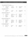
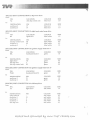
REAR HARNESS CONNECTORS - Revision 3
U36) ALARM:
1 x 12 way AMP Mate N Lok
DESCR1PTION
PIN
2
door pin
boot/bonnet
3
alarm active
S
e",th
6
ignition
S
lh indicator
9
11
battery
12
rh indicator
COLOUR
white/purple
blue/black
pink
black
g'''''''
green/ red
,ed
green/ white
SIZE
0.5
O.S
0.5
1.0
0.5
1.0
1.0
1.0
DESTINATION
PIN
splice joint 6
splice joint 7
splice joint 3
earth point
splice joint 2
splice joint 4
splice joint 1
splice joint 5
U37) ALARM ACCESSORY SOCKET:
x 6 way Trident Snap Together
1
PIN
1
2
3
4
5
DESCRIPTION
battery
ignition
e",th
alarm active
door pin
COLOUR
red
pink
white/purple
SIZE
1.0
0.5
1.0
0.5
0.5
splice joint 3
splice joint 6
COLOUR
,ed
blue/black
SIZE
0.5
0.5
splice joint 8
splice joint 7
COLOUR
SIZE
0.5
0.5
earth point
splice joint 9
SIZE
05
05
DESTINA116N
splice joint 7
earth point
green
black
DESTINATION
PIN
splice joint 1
splice joint 2
earth point
03S,A, )3S,S) BOOT COURTESY LAMP,
2 x 6.3mm spades + covers
PIN
DESCR1PTION
battery
signal(switch)
DESTINATION
PIN
U39) BOOT LID,
1 x 2 way Trident Snap Together
PIN
1
2
DESCR1PTION
earth
brake lamp
black
green/ purple
DESTINATION
PIN
U40,A, )40,B) BOOT LID SWITCH,
1 "" 6.3mm spade + cover I 2 M4 eyelet
=0
PIN
1
2
DESCRIPTION
boot lid switch
wth
COLOUR
blue / black
black
Hosted and optimised by www.TheTVRSite.com
PIN
..,
(J41:A, )41:8) BOOT LOCK SOLENOID:
2 x 6.3mm spades + covers
DESCRIl'TION
PIN
battery
lock control
DESTINATION
PIN
0.5
splice joint 10
door control unit conn 3
Al
COLOUR
black
black/red
SIZE
0.5
0.5
DESTINATION
PIN
earth point
door control unit conn 1
AB
DESCRIl'TION
dip power
dip beam out
dim dip in
e",th
head lamps on
main beam in
COLOUR
red / yellow
blue/ red
red/black
black
blue/yellow
blue/while
ignition
green
SIZE
2.0
2.0
1.0
0.5
O.S
0.5
0.5
COLOUR
SIZE
red
red/blue
0.5
(42) BOOT RELEASE SWITCH:
1 x 2 way Trident Snap Together
PIN
1
2
DESCRIl'TION
e",th
release signal
U43) DIM DIP CONTROL UNm
1 x MIC IV 9 way housing
PLN
Al
A2
A4
AS
Bl
B2
B3
DESTINATION
lights control unit
splice joint 11
dim dip unit
earth point
dim dip unit
splice joint 12
PIN
A6
6
2
splice joint 13
U44,A, ),.,., )44,C, )44,0, )44,10. )44,F) DIM DIP UNm
6 x 6.3mm spades & covers
PIN
1
2
3
4
5
6
DESCRIl'TION
COLOUR
ignition
head lamps on
battery
green
ea<th
sideJamp
dim dip
blue/yellow
<od
black
red/white
red/black
SIZE
0.5
0.5
1.5
1.5
0.5
1.0
DESTINATION
PIN
splice joint 13
dim dip control unit
fusehoard block F
Bl
30AL
earth point
splice joint 15
dim d ip control unit
Hosted and optimised by www.TheTVRSite.com
A4
,,
CERBERA SERVICEI"WORKSH
P MANUAL
DOOR LOCK CONTROL UNIT:
Con.nector 1: 045) 1 x AMP MlC IV 17 way housing
PlN
DESCRIPTION
COLOUR
A1
drivers pin sw,
lock button
drvrs. inner reI.
pass. inner rei.
pass. outer rei.
white / purple
black/white
orange/white
A2
A3
A4
A6
A7
A8
Bl
B2
B3
B4
BS
B6
B7
B8
B9
drvrs. outer rei.
boot release
pass. pin sw.
drvrs. win. pos.
alarm active
pass win pos.
driver win.down
pass. win. up
pass. win. down
driver win. up
road speed
orange/white
orange
orange
black/red
white/purple
blue/yeUow
pink
blue/ red
yellow/green
red / black
red /green
yellow Iblack
slate
SIZE
0.5
0.5
DESTINATION
splice joint 19
multiway 1
multiway 1
multiway 1
multiway 1
multiway 1
hoot release switch
spliced joint 20
multiway 1
splice joint 3
mu ltiway 1
multiway 1
multiway 1
multiway 1
multiway 1
splice joint 16
PlN
SIZE
0.5
0.5
DESTINATION
earth point
splice joint 17
PlN
SIZE
0.5
0.5
1.0
0.5
0.5
DESTINATION
PIN
0.5
0.5
0.5
0.5
0.5
0.5
0.5
0.5
0.5
0.5
0.5
0.5
0.5
0.5
13
2
8
9
3
2
6
12
35
34
33
36
Connector 2: U46) 1 x AMP MIC IV 9 way housing
PIN
DESCRIPTION
COLOUR
A1
earth
battery
black
red
AS
DOOR LOCK CONTROL UNIT:
Connector 3: 047) 1 x AMP MJC IV 9 way housing
PlN
DESCRIP1l0N
COLOUR
A1
boot motor
battery (drv lock)
eMth
battery (pass lock)
courtesy lamp
drivers lock 1
drivers lock 2
pass. lock I
pass. lock 2
red/blue
'ed
black
red
pwple/ red
blue/orange
blue/green
blue/white
blue/yellow
A2
A4
AS
B1
B2
B3
B4
B5
0.5
0.5
0.5
0.5
boot lock
splice joint 18
earth point
splice joint 10
multiway 2
drivers door lock molor
drivers door lock motor
pass. door lock motor
pass. door lock motor
11
Connector 4: U48) 1 x AMP MJC IV 9 way housing
PlN
DESCRIPTION
A1
eMth
drivers win. 1
pass. wm. 1
earth
drivers win. 2
battery(drv win)
A2
A4
AS
B1
B2
B3
B4
65
LED
battery (pass win)
pass. win. 2
COLOUR
black
yeUow / black
red /black
black
yellow / green
<od
black / red
md
red / grccn
SIZE
1.5
1.5
1.5
1.5
1.5
1.5
0.5
1.5
1.5
DESTINATION
earth point
multi way 1
multiway 1
earth point J
multiway 1
splice joint 17
multiway 1
splice jOint 18
multiw<ly 1
Hosted and optimised by www.TheTVRSite.com
PlN
4
10
5
,.
11
..
<>- .
,
<t .'.
~
U49:A, J49:B) DRIVER'S DOOR LOCK MOTOR:
2 x 6.3mm spades + covers
PIN
DESCRIPTION
motor drive 1
motor drive 2
COLOUR
blue/orange
blue/ green
SIZE
0.5
0.5
DESTINATION
door control unit (ann 3
door control unit (ann 3
PIN
B2
83
SIZE
0.5
0.5
DESTINATION
multi way 2
PIN
3
earth point
SIZE
0.5
0.5
muJtiway 1
earth point
U50) DRIVER'S SEAT BELT,
1 x 2 way Trident Snap Together
PIN
DESCRIPTION
driver's seat bell
earth
I
2
U51) FUEL LEVEL SENDER:
1 x 2 way sealed RaCfcnday
PIN
DESCRIPTION
fuel level
B
A
earth
COLOUR
slate/black
black
COLOUR
green/ black
black
DESTINATION
PIN
20
US2:A, J52:B)FUEL PUMP:
1 x M4 eyelet:: ; 1 x MS eyelet =
(l. l uF suppresser to be mounted across pump + to chassis ground)
PIN
+
DESCRIPTION
pump drive
COLOUR
yellow/black
earth
black
DESCRIPTION
COLOUR
SIZE
DESTINATION
inertia switch
earth point
PIN
1.5
1.5
SIZE
DESTINATION
PIN
FUSEBOARD
PIN
USE
(DUE TO TIiE COMPLEXITY OF TIiE FUSEBOARD PLEASE REFER TO TIiE
SEPERATE SUB SECTION DEDICATED TO TIiE FUSEB{JARD CONNECTIONS)
U53) IGNITION CONTROL UNm
1 x AMP MlC IV 9 way housing
PIN
DESCRIPTION
Al
battery (ign)
A2
ignition earth
AS
battery (start)
B1
ign output
82
start
B3
stop
SS
s tarter
COLOUR
,.d
black
' 00
white
black / white
black/red
white/ red
SIZE
1.5
0.5
0.5
1.5
0.5
0.5
0.5
DESTINATION
spliced joint 23
multiway 2
spliced joint 23
fuseboard b lock B
multiway 1
mu ltiway 1
immobiliser
...
PIN
15
15
18
19
B
.J
Hosted and optimised by www.TheTVRSite.com
CERBERA SERVICEIWORKSH
• PMANUAL
(54) IMMOBILISER:
1 x 12 way Trident Snap Together
PeN
DESCRIPTION
1
2
ignition
battery
earth1
ignition (ECU)
ignition (ECU)
3
4
5
6
8
10
12
11
earU12
starler
starter
fuel pump
fue l pump
COLOUR
green
'00
black
green
green
black
white/red
white/red
yellow
yeUow
SIZE
0.5
0.5
1.0
1.0
1.0
1.0
0.5
0.5
O.S
0.5
DESTINATION
PeN
splice joint 2
splice joint 1
earth point
tuseboard block B
multiway 2
earth point
ignition control unit
fuseboard block 0
15A
9
fuseboard block K
multiway 2
65
85L
2
2
055) INDICATOR CONTROL UNIT:
1 x AMP MIC rv 17 way housing
PeN
DESCRIPTION
AI
rh indicator
flasher input
lh indicator
A2
A3
A6
A7
A8
A9
61
64
69
ignition
flash power
battery
hazard signal
'h turn
Ih turn
earth
COLOUR
green/white
It. green/brown
green/red
green
green/yellow
red
brown/black
green/white
green/red
black
SIZE
1.0
1.0
1.0
1.0
1.0
1.0
0.5
0.5
0.5
0.5
DESTINATION
splice joint 5
fuseboard b10ck A
splice joint 4
fuseboard block M
fuscboard block A
fuseboard block H
multi way ]
multi way 1
multiway 1
PeN
87M
75AS
85M
58R
31
30
29
earth point
(J56) INERTIA SWITCH:
1 x 3 way AMP Econo--scal - (viewed cable entry with lock bar to top)
PeN
DESCRIPTION
COLOUR
I/h
mid
' /h
pump input
pump output
warning lamp
yellow
yellow/black
black /green
SIZE
1.5
1.5
0.5
DESTINATIO
fuseboard block K
fuel pump
multiway 1
Hosted and optimised by www.TheTVRSite.com
PlN
4
+
24
~ )f.'.'
, .".
•
'.
..I.
.
:, I
• -' ... ! '
!"o;.
."
"
U57) LIGHTS CONTROL UNIT:
1 x AMP MlC rv 17 way housing
PLN
AI
A2
A3
A4
A6
A7
AB
A9
Bl
82
83
B5
56
BB
B9
DESCRJPTION
COLOUR
rear fog lamps
fog lamp w / I
sidelamps
sidelamp signal
dip beam drive
battery (dip)
ignition
battery (main).
battery (side)
fog lamp signal
head lamp sig.
dip beam sig.
main beam sig.
rh main beam
rh main beam
yellow/red
yellow/red
red /white
white
red /yellow
red
green
,ed
,ed
yellow
blue
blue/red
blue/white
blue/white
blue/white
SlZE
1.0
0.5
1.0
0.5
2.0
2.0
0.5
2.0
1.5
0.5
0.5
0.5
0.5
1.5
1.5
DESTINATION
rh lamp cluster
multiway 1
splice joint 15
multiway 1
dim dip control unit
fuseboard block H
splice joint 13
fuseboard block M
fuseboard block G
multiway 1
multiway 1
multiway 1
multiway 1
multiway 3
splice joint 12
PLN
5
23
16
AI
308
3QAC
49
15
17
27
28
3
"',
NUMBER PLATE LAMPS:
Connector 1: 058:A, J58:B) 2 x 6,3mm spades + covers
PLN
DESCRll'TION
COLOUR
SIZE
side1amp
earth
red /while
black
0.5
0.5
splice joint 25
earth point
DESTlNATION
Connector 2: 059:A, J59:B) 2 x 6.3m.m spades + covers
sidelamp
red/white
black
earth
0.5
0.5
splice joint 25
earth point
PIN
U60,A, }60,8)PASSENGER'S DOOR LOCK MOTOR,
2 x 6.3mm spades + covers
PLN
DESCRIPTION
COLOUR
motor drive 1
motor drive 2
blue/ white
blue /yellow
SlZE
0.5
0.5
door control unH conn 3
door control unit conn 3
PLN
84
85
DESTINATION
PIN
DESTINATION
U61) PURGE VALVE,
1 x 2 way Raffenday seaJed
PLN
A
8
DESCRIPTION
COLOUR
purge power
purge drive
yeUow / black
purple/black
SlZE
0.5
0.5
splice joint 21
multiway 2
,
062:A, J62:B} REAR SPEAKER (Right hand) :
1 x 4.8 AMP faston type = + / 1 x 2 .8 AMP fastcn type = -
PLN
+
DESCRlPllON
COLOUR
rh rear spkr ...
rh rear spkr -
slate/red
black/slate
19
SlZE
0.5
0.5
DESTINATION
multi way 2
multiway 2
Hosted and optimised by www.TheTVRSite.com
PLN
7
8
)
,
CERBERA SERVlCEllVORKSH
PNlANUAL
063:A, J63:81 REAR SPEAKER (Left hand):
I 1 x 2.8 AMP faston type -= •
1 x 4.8 AMP faston type = +
PIN
+
DESTINAnON
lh rear spkr +
Ih rear spkr
+
COLOUR
green/red
black/green
SIZE
0.5
O.S
DESllNATION
multiway 2
multiway 2
PIN
5
SIZE
2.0
2.0
DESTINATION
PIN
RL
6
064,A, J640BIREAR WINDOW,
2 x 6.3mm spades + covers
PIN
rear window
COLOUR
purple
earth
black
DESCRlPTION
fuscboard block F
earth point
065) REAR LAMP CLUSTER ILEm,
1 x Ford 5 way tiJner connector
PIN
I
2
3
4
5
DESCRlPTION
reverse lamp
mth
lh indicator
brake lamp
sideJamp
COLOUR
SIZE
lightlt. green/brown 0.5
black
1
green/red
0.5
0.5
green/purple
red /white
0.5
DESTINATION
PIN
multiway 223
earth point
splice joint 4
splice joint 9
splice joint 25
066) REAR LAMP CLUSTER IRlGH1}
1 x Ford 5 way timer connector
PIN
1
2
S
3
4
DESCRlPTION
brake lamp
sidclamp
fog lamp
rh indicator
earth
COLOUR
green/purple
red/white
yellow/red
green/white
black
SIZE
O.S
0.5
0.5
0.5
DESTINATION
splice joint 9
splice joint 25
lights control unit
splice joint 5
earth point
PIN
Al
067) SPEEDO SPEED SENSO'"
1 x 2 way 1ST sealed connector
PIN
DESCRDPTION
COLOUR
00
0
earth
black
0.5
DESTINATION
earth point
speed signal
slate
0.5
splice joint 16
SIZE
Hosted and optimised by www.TheTVRSite.com
PIN
·
u
.........
~.;.
.
-.:
",,~.,
REAR MULTlWAY CONNECTIONS - Revision 3
033) MULTlWAY CONNECTOR 1:
1 x 36 way Trident Snap Together
(Note: all identically coloured wires must be marked with their associated cavity number)
PIN
1
2
3
4
5
6
7
8
9
10
11
12
13
14
15
16
17
18
19
20
21
22
23
2.
25
26
27
28
29
30
31
32
33
34
35
36
DESCRJPTION
driver door pin sw.
driver inner release
driver outer release
driver window 1
driver window 2
driver window pas.
pass. door pin sw.
pass. inner release
pass. ou ter release
pass. window 1
pass. window 2
pass. window pos.
lock button sig.
locked LED sig.
fog lamp sw. sig.
sidelamp sw. s ig.
headlamp sw. sig.
start signaJ
stop signal
fuel level s ig.
bonnet switch s ig.
rear window sig.
rear fog w / I
inertia switch w /1
main beam w 1I
road speed signal
dip beam signal
m..'1in beam signal
Ih turn signal
rh turn signal
hazard signal
horn s ignal
pass. wm. down sig.
pass. win. up sig.
driver win.down sig.
driver win. up sig .
COLOUR
white/purple
orange/white
orange
yellow Iblack
yellow I green
blue/yeUow
white/purple
orange/white
orange
red/black
red /green
blue/ red
black/white
black/ red
yellow
white
blue
black/white
black/red
green/black
blue/black
purple/red
yellow/red
blacklgreen
blue/white
slate
blue /red
blue/white
green/red
green/white
brown/black
purple/black
red /green
red/black
yellow / green
yellow Iblack
SIZE
0.5
0.5
0.5
1.5
1.5
0.5
0.5
0.5
0.5
1.5
1.5
0.5
05
05
05
0.5
0.5
05
05
05
05
05
0.5
05
0.5
0.5
05
05
0.5
05
05
05
05
05
05
0.5
DESTINATION
splice joint 19
door lock ECV conn 1
door lock ECV conn 1
door Jock ECV conn 4
door lock ECV conn 4
door lock ECU conn 1
splice joint 20
door lock ECV (onn 1
door lock ECV conn I
door lock ECU conn 4
door lock ECV conn 4
door lock ECU corm 1
door lock ECU corm 1
door lock ECU corm 4
lights ECU
lights ECU
lights ECU
ignition ECU
ignition ECU
fuel level sender
splice joint 7
fuseboard block H
lights ECU
inertia switch
splice joint 12
splice joint 16
lights ECU
lights ECU
indicators ECU
indicators ECU
indicators ECU
fuseboard block A
door lock ECU coon 1
door lock ECU coon 1
door lock ECU corm 1
door lock ECU corm 1
Hosted and optimised by www.TheTVRSite.com
PIN
A3
A7
A2
81
82
A4
A6
A4
85
84
')
A2
83
82
A4
83
82
83
8
SOW
A2
85
86
B4
81
A9
86K
87
86
85
88
)
CERBERA SERVlCEIWORKSH
PlWANUAL
(J34) MULTIWAY CONNECfIQN 2:
1 x 24 way Trident Snap Together
(Note: aU identically coloured wires must be marked with their associated cavity number)
PIN
1
2
3
4
5
6
7
8
9
10
11
12
13
14
15
16
17
18
19
20
21
22
23
24
DESCRIPTION
ignition (wipers)
fuel pump signal
driver's seat belt
ignition
Ih rear spkr+
lh rear spkr·
rh rear spkt+
rh rear spkrignition (inject)
brake lights drive
courtesy Jamp drive
ignition (coils)
ignition
battery
ignition control
radiator fan 2 sig.
lambda heat
ignition
purge valve drive
battery
ignition
radiator fan 1 sig.
reverse lamps drive
ignition
COLOUR
green
yeUow
slate/black
green
g<een/red
black/green
sla te/red
black/slate
green
green/purple
purple/ red
green
green
red
black
green/pink
yellow /black
green
purple/black
red
g<een
g<een/pink
It. green/brown
g<een
SIZE
1.5
0.5
O.S
2.0
0.5
0.5
0.5
0.5
1.0
0.5
0.5
1.5
1.0
1.5
0.5
0.5
0.5
1.0
0.5
1.0
1.0
0.5
0.5
2.0
DESTINATION
fuseboard block 0
immobiliser
drivers seat belt
fuseboard block J
left rear speaker
PIN
75A
11
2
7SAL
+
left rear speaker
right rear speaker
+
right rear speaker
immobiliser
splice joint 9
splice joint 6
fuseboard block R
fuseboard block H
splice joint 8
ignition ECU
fuseboard block G
splice joint 21
fusebrnud block J
purge val\le
fuseboard block I
splice joint 14
fuseboard block G
lefl lail lamp assy.
splice joint 14
5
58L
A2
71
SBAS
B
58D
86N
1
035) MULTIWAY CONNECTION 3:
1 x 19 way Grote and Hartmann (4 power + 15 signal)
(Note: all identically colo u.red wires must be marke d with their associated cavity number)
PIN
1
2
3
4
5
6
7
8
9
10
11
12
13
14
15
16
17
18
19
SIZE
1.5
1.0
1.5
0.5
DESTINATION
splice joint 12
fuseboard block K
lights ECU
splice joint 15
red/white
pink
0.5
3.0
splice joint 15
fuseboard block F
white/red
pink
3.0
3.0
fuseboard block E
fuseboard block E
DESCRIPTION
rh main beam
horn power drive
U1 main beam
rh s idelamps
COLOUR
blue / white
purple/white
blue/white
red /white
lh side1amps
engine fan 1
starter solenoid
engine fan 2
,
rh indicator
instru ment lamps
U1 indicator
rh dip beam
green/while
red/white
green/red
blue/red
1.0
1.0
1.0
1.0
splice joint 5
splice joint 15
s plice joint 4
splice joint 11
U1 dip beam
b lue/red
1.0
splice joint 11
Hosted and optimised by www.TheTVRSite.com
PIN
6
88
55
87LA
B7H
.
f"'~;'_
'.:-
" >~., .
... '..- ...
.
.
V.', . .
"
.
REAR SPLICED JOINT CONNECTIONS - Revision 3
SPLICE JOINT] : battery supply from fuse 3
from:
PIN
30A
LOCATION
fuseboard block G
COWUR
red
SIZE
1.5
DESTINATION
alarm
alarm accessory
immobiliser
PIN
red
COWUR
1.0
",d
red
SIZE
COWUR
SIZE
1.0
to:
SPLICED JOINT 2: ignition supply from fuse U
from:
PIN
LOCATION
15A
fuscboard block C
g'een
1.0
0.5
i',
to:
DESTINATION
alarm
alarm accessory
immobiliser
PIN
COWUR
green
green
gyeen
SPLICED JOINT CONNECTION 3 : alarm slate signal
from:
PIN
LOCATION
COWUR
alarm
5
pink
to:
PIN
COWUR
DESTINATION
1
alarm accessory
pink
door lock ECV conn 1 B3
pink
SPLICED JOINT CONNECTION 4: left hand indicator
from:
PIN
LOCATION
COWUR
A3
indicator ECU
green / red
to:
COWUR
DESTINATION
PIN
multiway 3
16
green/red
alarm
9
green/red
left rear lamp duster 3
green/red
SPLICED JOINT CONNECTION 5: right hand indicator
from:
PIN
LOCATION
COWUR
A1
indicator ECU
green I while
SIZE
0.5
0.5
0.5
SIZE
0.5
SIZE
0.5
0.5
SIZE
1.0
1.0
0.5
SIZE
1.0
10:
DESTINATIO:'.J'
multiway 3
alaml
right rear lamp duster
PIN
14
12
3
COWUR
green/ white
green /white
green / while
.~
SIZE
1.0
SIZE
1.0
1.0
0.5
•
DESCRIPTION
Hosted and optimised by www.TheTVRSite.com
,,
CERBERA SERVlCE/l-VORKSH
S PLICED JO INT CONNECfIQN 6 : door pi n common
from:
PrN LOCATION
COLOUR
SIZE
2
alarm
white/ purple
PNIANUAL
0.5
to:
PIN
SIZE
splice joint 19
COLOUR
white/purple
splice joint 20
whi te/purple
0.5
white/purple
0.5
DESTINATION
5
alarm accesssory
(note: each d iode is
Cl
0.5
via diode - see
note
via diode - see
nole
lN4001 silicon diode with the band fadng away from this splice)
S PLICED JO I NT CONNECTION 7: boo tlbonnet pin s w itc hes
ITom:
LOCATION
boot lid switch
COLOUR
blue/ black
0.5
DESTINATION
alarm
boot courtesy lamp
PIN
3
SIZE
multiway 1
21
COLOUR
blue/black
blue/black
blue/black
PIN
SIZE
to:
DESCRIPTION
0.5
0.5
0.5
SPLI CED JO INT CONNECTION 8: batte ry supply from f use 8
from:
PIN
56AK
LOCATION
fuseboard block C
COLOUR
red
SIZE
DESTINATION
PON
14
COLOUR
,ed
red
SIZE
boot courtesy lamp
multiway 2
COLOUR
green/purple
SIZE
COLOUR
SIZE
1.5
to:
SPUCED JOINT CONNECIlON 9: brake Jamp drive
from:
PIN
LOCATION
10
multiway 2
0.5
1.5
0.5
to:
DESTINATION
right rear Jamp cluster
left rear lamp cluster
boot lid
PIN
I
4
2
green/purple
green/purple
STeen/purple
SPLI CED JOINT CONNECfION 10: battery s upply from fus e U
from:
PIN
LOCATION
COLOUR
,ed
56BL
fuseboard block D
to:
PIN
COLOUR
DESTINATION
,ed
boot lock solenoid
door lock ECU conn 3 A.5
red
0.5
0.5
0.5
SIZE
0.5
SIZE
0.5
0.5
Hosted and optimised by www.TheTVRSite.com
;-,
S PLI CED JO INT CONN ECTION 11 : dip bea m drive
(rom:
PIN
LOCATION
dim dip control unit
COLOUR
A2
DESTINATION
multiway 3
multiway 3
PIN
17
19
COLOUR
bl ue/red
SIZE
2.0
to:
blue/red
blue/ red
S PLICE D JOI NT CON N ECTION 12: rig ht hand main beam d ri ve
from:
PIN
LOCATION
COLOUR
B9
lights ECU
blue/whi te
DESTINATION
dim dip control unit
multiway 1
multiway 3
PIN
B2
COLOUR
SIZE
1.0
1.0
SIZE
1.S
to:
25
blue/white
blu e/white
blue/white
S PLI CED JO INT CO NNECTION 13: ignition s uppl y from fus e 7
h orn:
PIN
LOCATION
COLOUR
58L
fuseboard block 0
green
SIZE
0.5
0.5
1.5
I
SIZE
1.0
to:
DESTINATION
lights ECV
dim dip unit
dim dip control uni t
PIN
COLOUR
AB
1
green
green
B3
g.een
SIZE
0.5
0.5
0.5
SPLI CE D JOINT CONNECTION 14: ig nition s upply from fuse 17
from:
PIN
LOCATION
COLOUR
75AK
fuseboard block M
green
DESTINATION
mul tiway 2
multiway 2
PIN
21
COLOUR
g.een
24
green
SIZE
2.0
to:
J
SIZE
1.0
2.0
SPLICED JOINT CON N ECTION 15: sidelamp drive
from:
PIN
A3
LOCATION
lights ECV
COLOUR
PIN
COLOUR
15
red/white
red / white
red / white
red/white
SIZE
1.0
to:
DESTINATION
spike joint 25
multiway 3
multiway 3
multiway 3
dim dip unit
4
6
5
red/white
red/whi le
SIZE
0.5
0.5
0.5
05
0.5
t
Hosted and optimised by www.TheTVRSite.com
CERBERA SERVICEIWORKSH
PJldANUAL
\
SPLICED JOINT CONNECfJON 16: road speed signal
from:
PIN
COLOUR
speedo speed sensor
LOCATION
slate
DESTINATION
PIN
COLOUR
door lock EeU cann 1
B9
26
slate
SIZE
0.5
to:
multiway 1
s late
StzE
0.5
0.5
SPLICED JO INT CONNECfION 17: battery s upply from f use 10
from:
PIN
LOCATION
COLOUR
56BR
fuseboard block 0
red
DESTINATION
door lock EeU conn 2
door lock ECV conn 4
PIN
COLOUR
AS
red
,cd
StzE
1.5
to:
B2
StzE
0.5
1.5
SPLICED JOINT CONNECfION 18: battery supply from fuse 9
from:
PIN
LOCATION
COLOUR
56AL
fuseboard block D
red
SIZE
1.5
to:
DESTINATION
PIN
door lock EeU conn 3 A2
door lock ECU conn 4 B4
COLOUR
red
red
SIZE
0.5
I.S
SPLICED JOINT CONNECTION 19: driver's pin s w itch
from:
PIN
1
LOCATION
multiway 1
COLOUR
white/purple
5tzE
0.5
PIN
COLOUR
white/purple
StzE
0.5
white/purple
0.5 via diode
(see note on
splice joint 6)
to:
DESTINATION
door lock Eeu conn 1
splice joint 6
A1
SPLICED JOINT CONNECfION 20: passenger's pin switch
from:
PIN
7
LOCATION
multiway 1
COLOUR
white/purple
SIZE
0.5
COLOUR
SIZE
to:
DESTINATION
PIN
door lock EeU conn 1 B1
splice joint 6
white/purple
white/purple
0.5
0.5
via diode
(see note on
splice joint 6)
Hosted and optimised by www.TheTVRSite.com
t.'
.
-'. "
"... .
_ --
:.'.~ 1
•
~,:,.""'''' ',"
1)
SPLICE JOINT CONNECTION 21 : power supply from fuel pump to ancillaries
from :
LOCATION
COLOUR
SIZE
PIN
fuseboard block K
yellow Iblack
1.0
8
to:
DESTINATION
purge valve
multiway 2
PIN
A
17
COLOUR
yellow /black
yellow /black
SIZE
0.5
0.5
SPLlCE}OINT CONNECTION 22: mas ter ignition supply to auxiliary relay coils
from:
PIN
LOCATION
COLOUR
SIZE
white
15
fuseboard block 1
0.5
to:
DESTINATION
PIN
COLOUR
SIZE
white
fuseboard block G
75
0.5
fuseboard block G
85N
white
0.5
SPLlCE)OINT CONNECTION 23: battery supply from fuse 20
from:
PIN
LOCATION
COLOUR
30AS
fuseboard block P
red
to:
DESTINATION
PIN
COLOUR
ignition ECU
A1
red
ignition ECU
A5
red
SPLICED JOINT CONNECTION 24: un-fused battery s upply to fuses
from:
PIN
LOCATION
COLOUR
fuseboard block L
(terminate as splice joint
into the large spade)
to:
DESTINATION
PIN
COLOUR
brown
fuseboard block F
568
fuseboard block G
57R
brown
fuseboard block I
56A
brown
SPLICED JOINT CONNECTION 25: s idelamp dri ve
from:
PIN
LOCATION
splice joint 15
to:
DESTINATION
PIN
number p late lamp
number plate lamp
right rear lamp cluster 2
left rear lamp cluster
5
SIZE
1.5
SIZE
1.5
0.5
SIZE
SIZE
2.0
1.5
2.0
COLOUR
red/white
SIZE
0.5
COLOUR
red/white
red/white
red / white
n.>d/ white
SIZE
0.5
0.5
0.5
0.5
,;
.I
)
Hosted and optimised by www.TheTVRSite.com
CERBERA SERVICEllVORKSH
SPUCED JOINT CONNECTION 26: battery supply from fuse 8
from:
COLOUR
PIN
LOCATION
S6AR
fuseboard block 0
red
PlWANUAL
SIZE
1.0
to:
DESTINATION
PIN
COLOUR
fuseboard block A
30K
85K
red
red
fuseboard block A
SIZE
1.0
0.5
.,
Hosted and optimised by www.TheTVRSite.com
I')
REAR HARNESS FUSEBOARD CONNECTIONS - Revision 3
(Note: all identically coloured wires must be marked with their associated cavity number)
(}68)FU5EBOARD BLOCK A:
AMP grey 8 way
PIN
DESCRIPTION
COLOUR
30k
hom power
not connected
horn power
red
30m
85k
85m
86k
86m
87ak
87m
flasher power
horn signal
earth
not connected
flasher output
SIZE
1.0
DESTINATION
black
0.5
1.0
0.5
0.5
earth point
It. green/brown
1.0
indicator ECV
red
green/yellow
purple /black
PIN
splice joint 26
splice joint 26
indicator ECV
multiway ]
A7
32
A2
"
(69)FUSEBOARD BLOCK 8:
AMP black 8 way
PIN
IS
15a
87f
DESCRIPTION
COLOUR
master input
white
fuse 12 output
not connected
green
SIZE
1.5
1.0
DESTINATION
ignition ECV
immobiliser
PIN
SIZE
1.5
1.0
DESTINATION
PIN
Bl
4
FUSEBOARD BLOCK Co (J70)
A!v1P blue 8 way
PIN
DESCRIPTION
S6AK
fuse 8 output
15A
fuse 12 output
COLOUR
red
green
splice joint 8
splice joint 2
,
l I
Hosted and optimised by www.TheTVRSite.com
CEREERA SERVICE/WORKSHOP MANUAL
071) FUSEBOARD BLOCK D,
AMP green 8 way
PIN
B5L
75A
56BL
56BR
56AR
56AL
P
5BL
DESCRIPTION
crank signal
fuse 15 output
fuse 11 output
fuse 10 output
fuse B output
fuse 9 output
fuel power
fuse 7 output
COLOUR
white/ red
green
,ed
red
red
red
red
green
SIZE
0.5
1.5
1.0
1.5
1.0
1.5
1.5
1.0
DESTINATION
immobiliser
multiway 2
splice joint 10
splice joint 17
splice joint 26
splice joint 18
link block M
splice joint 13
PIN
10
1
30AZ
U72)FUSEBOARD BLOCK E:
AMP yeUow 8 way
PIN
DESCRIPTION
67H
B7L
55
SBR
67LA
RS
engine (an 2
not connected
not connected
fuse 6 output
starter solenoid
white/red
\-viI\dow power
red
COLOUR
pink
red
SIZE
3.0
1.5
3.0
1.5
DESTINATION
PIN
multiway 3
10
link block E
multiway 3
RS
9
5BR
link block E
073)FUSEBOARD BLOCK F,
AMP brown Sway
PIN
30AL
SOZ
55
56B
57L
RL
DESCRIPTION
COLOUR
fuse 4 output
red
black
pink
earth
engine fan 1
pwr fuses 10+ 11
power fuse 7
heated window
brown
white
purple
SIZE
1.5
0.5
3.0
2.0
2.0
1.5
PIN
DESTINATION
dim dip unit
earlh point
multiway 3
splice joint 24
link block M
rear window
3
7
755
+
074) FUSEBOARD BLOCK G,
AMP red B way
PIN
3DA
31
49
57R
71
75
85N
86N
DESCRIPTION
fuse 3 output
earth
fuse 2 output
pWI fuse 6
fan 2 drive
relay power
relay power
fan I drive
COLOUR
red
black
<cd
brown
gyeen/pink
white
white
green/ pink
SlZE
1.5
0.5
1.5
1.5
0.5
0.5
0.5
0.5
PIN
DESTINATION
splice joint]
earth point
lights ECU
splice joint 24
multiway 2
splice joint 22
splice joint 22
rnultiway 2
BI
16
22
/
075) FUSEBOARD BLOCK H,
At'viP black 6 way
PIN
30B
SOW
DESCRIPTION
fuse 4 output
window drive
COLOUR
<cd
purple/red
SIZE
1.5
0.5
DESTINATION
lights EeU
multiway 1
pIN
Hosted and optimised by www.TheTVRSite.com
A7
22
.
.
58L
58R
87F
.
"j"'.
fuse 7 output
fuse 6 output
not connected
.'
.. .
~
1.0
1.0
multiway 2
indicator ECU
13
AS
SrzE
0.5
2.0
1.0
DESTINATION
splice joint 22
splice joint 24
multiway 2
PIN
DESTINATION
link block J
link block J
multiway 2
PIN
8'een
SIZE
1.0
1.0
1.0
g<een
2.0
green
,.d
(176 )FUSEBOARD BLOCK I:
AMP Red 6 way
PIN
15
56A
58D
75AW
DESCRIPTION
relay power
pwr fuses 8+9
fuse 14 output
not connected
COLOUR
white
brown
,.d
20
077)
FUSEBOARD BLOCK),
AMP yellow 6 way
PIN
30
58
58AS
75AH
75AL
DESCRlPTlON
un-fused bat!
pwr fuse 14
fuse 18 output
not connected
fuse 17 output
COLOUR
brown
brown
58
30
18
muJtiway 2
4
07S) FUSEBOARD BLOCK K,
AMP relay base style block
PIN
S
6
5
4
2
DESCRIPTION
purge power
horn drive
not connected
fuel pump
pump drive
COLOUR
yellow /black
purple/white
yellow
yelJow
SrzE
1.0
1.0
1.5
0.5
DESTINATION
splice joint 21
multiway 3
inertia switch
immobiliser
PIN
2
12
U79:A, J79:8, J79:C, J79:D) FUSEBOARD BLOCK L:
9.5 mm spades x 4
PIN
L
L
L
DESCRIPTION
lOOA/2
100A/2
un-fused bat!
, )
COLOUR
battery supply
battery supply
termi na te as
splice joint
SIZE
COLOUR
SrzE
2.0
1.5
2.0
1.0
DESTINATION
PIN
splice joint 24
OSO,A. )SO,B FUSEBOARD BLOCK M, )
2 way + 3way spade housings
PIN
30AC
30AZ
75AK
75AS
755
DESCRIPTION
fuse 21 output
fuse 19 output
fuse 17 output
fuse 18 output
un-fused ign
red
,ed
green
green
white
2.0
DESTINATION
lights ECU
link block D
spike joint 14 /
indicator ECU
link block F
PIN
A9
P
A6
57L
I
Hosted and optimised by www.TheTVRSite.com
CERBERA SERVICEIWORKSH
PMANUAL
081 )FUSEBOARD BLOCK p,
1/ 4" Lucar
PIN
30AS
DESCRIPTION
fuse 20 output
PIN
1.5
DESTINATION
splice joint 23
SlZE
1.5
DESTINATION
multiway 2
PIN
12
COLOUR
red
SlZE
COLOUR
green
082) FUSEBOARD BLOCK R:
14" Lucar
PIN
DESCRIPTION
fuse 16 o utput
Hosted and optimised by www.TheTVRSite.com
1'~:
I!'
•
'"
",I;,.
,,~_~
.-
'it'';
••.f;~_
'
,
ij
Fuse No.
I
2
3
4
5
6
7
8
9
1
11
12
13
14
IS
16
17
18
19
20
21
Relay No.
1
2
3
4
5
6
7
8
9
10
11
Description
engine fan]
sidelamps, rear fog lamps
engine fan 2, alarm powered indicators
dip beam and dim dip headlamps
starter motor solenoid
rear window heater, hazard lamps
gauges, mirrors and radio, dim dip
homs, boot lamp, courtesy lamp, cigarette
drivers lock ,passenger's window
driver's window, door lock ECU
passenger's lock, boot lock
injectors, engine ECU, immobiliser
not used
engine ECU backup ,steering ECU supress
wipers, steering ECU supply
ignition coils
heating and ventilation system
indicators, reverse lamps, brake lamps
fuel pump, lambda heaters ,purge valve
master ignition
main beam
Description
Engine fan 1
Starter solenoid
(no service)
Fuel pump and emission control
Auxiliary ignition circuits
Horns
Engine fan 2
Heated rear window
(no service)
(no service)
Flasher unit
Size
30A
15A
30A
20A
30A
15A
lOA
15A
20A
20A
lOA
15A
lOA
20A
20A
25A
15A
20A
15A
20A
,
)'!
Part No,
M0643
M0643
M0509
M0383
M0643
M0643
M0643
,
M0225
(
\
Hosted and optimised by www.TheTVRSite.com
I