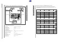
1
Service Manual
SAT
Grundig Service
STC 1200
Hotline Deutschland...
...Mo.-Fr. 8.00-16.30 Uhr
Technik:
TV
TV
SAT
VCR/LiveCam
HiFi/Audio
Car Audio
Telekommunikation
Fax:
0180/52318-41
0180/52318-49
0180/52318-48
0180/52318-42
0180/52318-43
0180/52318-44
0180/52318-45
0180/52318-51
Planatron (8.00-22.00 Uhr) 0180/52318-99
Ersatzteil-Verkauf:
...Mo.-Fr. 8.00-19.00 Uhr
Telefon:
Fax:
0180/52318-40
0180/52318-50
Zusätzlich erforderliche
Unterlagen für den Komplettservice
Additionally required
Service Manuals for the Complete Service
Service
Manual
Service
Manual
STC 1200
Sicherheit
Safety
Sach-Nr./Part No.
72010 023 3000
Sach-Nr./Part No.
72010-800.00
Btx * 32700 #
Sachnummer
Part Number 72010 023 3000
Änderungen vorbehalten
Subject to alteration
Printed in Germany
VK233 0998
Allgemeiner Teil / General Section
STC 1200
Es gelten die Vorschriften und Sicherheitshinweise gemäß dem Service Manual "Sicherheit",
Sach-Nummer 72010 800 0000, sowie zusätzlich die eventuell abweichenden, landesspezifischen Vorschriften!
D
The regulations and safety instructions shall be
valid as provided by the "Safety" Service Manual,
part number 72010 800 0000, as well as the
respective national deviations.
GB
Allgemeine Hinweise
General Notes
Sachnummern
Part Numbers
Durch die EDV-Umstellung wurden die bisherigen 10-stelligen
Sachnummern auf 12-stellige geändert.
Beispiel:
bisher:
29504-111.22
neu:
29504 111 2200
Während der Umstellphase können im Service Manual beide
Schreibweisen vorkommen.
Due to the conversion of the EDP system, the previous 10-digit part
numbers were change to 12-digit numbers.
Example: previous:
29504-111.22
new:
29504 111 2200
During the conversion of the system, either form may be found in
the Service Manual.
Inhaltsverzeichnis
Table of Contents
Seite
Page
Allgemeiner Teil ................................... 1-1... 1-8
General Section .................................. 1-1... 1-10
Meßgeräte / Hilfsmittel ................................................................. 1-2
Technische Daten ....................................................................... .1-3
Reparaturhinweis ......................................................................... 1-3
Schaltplansymbole ....................................................................... 1-3
Service und Sonderfunktionen ..................................................... 1-4
Montageanleitung für DNS 850 C ................................................ 1-5
Bedienungsanleitung ................................................................... 1-6
Test Equipment / Aids ..................................................................
Technical Data .............................................................................
Service Note ................................................................................
Circuit Diagram Symbols .............................................................
Service and Special Functions .....................................................
Fitting Instructions for DNS 850 C ...............................................
Operating Instructions ..................................................................
Schaltpläne und
Druckplattenabbildungen .................. 2-1... 2-21
Circuit Diagrams
and Layout of PCBs ........................... 2-1... 2-21
Schaltpläne
Descrambler-Platte ................................................................. 2-1
Backplane ............................................................................... 2-3
Netzteil .................................................................................... 2-7
Hybrid-Verstärker .................................................................. 2-11
Eingangsverteiler .................................................................. 2-12
Ausgangssammler ................................................................ 2-15
Bedien-Einheit ....................................................................... 2-19
Druckplattenabbildungen
Descrambler-Platte ................................................................. 2-2
Backplane ............................................................................... 2-5
Netzteil .................................................................................... 2-9
Hybrid-Verstärker .................................................................. 2-13
Eingangsverteiler .................................................................. 2-13
Ausgangssammler ................................................................ 2-17
Bedien-Einheit ....................................................................... 2-21
Circuit Diagrams
Descrambler Board ................................................................. 2-1
Backplane ............................................................................... 2-3
Power Supply .......................................................................... 2-7
Hybrid Amplifier ..................................................................... 2-11
Input Distributor ..................................................................... 2-12
Output Collector Field ........................................................... 2-15
Control Unit ........................................................................... 2-19
Layout of PCBs
Descrambler Board ................................................................. 2-2
Backplane ............................................................................... 2-5
Power Supply .......................................................................... 2-9
Hybrid Amplifier ..................................................................... 2-13
Input Distributor ..................................................................... 2-13
Output Collector Field ........................................................... 2-17
Control Unit ........................................................................... 2-21
Ersatzteilliste ........................................ 3-1... 3-3
Spare Parts List .................................... 3-1... 3-3
Allgemeiner Teil
General Part
Meßgeräte / Hilfsmittel
Test Equipment / Aids
Beachten Sie bitte das Grundig Meßtechnik-Programm, das Sie unter
folgender Adresse erhalten:
Please note the Grundig Catalog "Test and Measuring Equipment"
obtainable from:
Grundig Instruments
Test- und Meßsysteme GmbH
Würzburger Str. 150, D-90766 Fürth/Bay.
Tel. 0911/703-4118, Telefax 0911/703-4130
eMail: [email protected]
Internet: http://www.grundig-instruments.de
1-2
1-2
1-3
1-3
1-3
1-4
1-5
1-8
Grundig Instruments
Test- und Meßsysteme GmbH
Würzburger Str. 150, D-90766 Fürth/Bay.
Tel. 0911/703-4118, Telefax 0911/703-4130
eMail: [email protected]
Internet: http://www.grundig-instruments.de
GRUNDIG Service
STC 1200
Allgemeiner Teil / General Section
Technische Daten
Technical Data
Kassetten .............. 12 Steckplätze für maximal 24 Ausgangskanäle
Cassettes ............ 12 plug-in units for maximum 24 output channels
Eingangsfrequenzbereich ..................................... 950 … 2150MHz
Eingangsverteiler ........................................... 4 x 1-auf-9 (je -16dB)
Input frequency range ........................................... 950 … 2150MHz
Input distributor ........................................... 4 x 1-to-9 (-16dB each)
HF-Ausgangspegel ................................................... max. 106dBµV
Einstellbereich des HF-Pegelstellers
(Ausgangssammler) ............................................................ -20dB
RF output level .......................................................... max. 106dBµV
Adjustment range of RF level control
(Output collector field) ......................................................... -20dB
Netzspannung ........................................... 195V … 260V~; 50/60Hz
Leistungsaufnahme
(inklusive Fernspeisung) .......................... ca. 180W voll bestückt
Mains supply ............................................. 195V … 260V~; 50/60Hz
Power consumption
(incl. remote supply) ............. abt. 180W fully fitted with cassettes
zulässige Umgebungstemperatur,
ohne Be- und Entfeuchtung ................................... -20°C … 50°C
Permissible ambient temperature,
without humidification and dehumidification ........... -20°C … 50°C
Abmessungen (BxHxT) ............................... ca. 700 x 410 x 310mm
Dimensions (WxHxD) ................................. abt. 700 x 410 x 310mm
Gewicht ........................................................ ca. 50kg (voll bestückt)
Weight ..................................... abt. 50kg (fully fitted with cassettes)
Reparaturhinweis
Service Note
Um die hochfrequenztechnischen Vorschriften wie z.B. Störstrahlung,
Störleistung, Oszillatordrift, Einhaltung der Bild- und Tonnormen zu
gewährleisten, werden die Kassetten in der Fertigung mit großem
computerunterstütztem Meßgeräteaufwand abgeglichen.
Auch bei der Reparatur müssen nach jedem Eingriff in die Kassette alle
Parameter kontrolliert bzw. eingestellt werden.
To ensure the compliance with the regulations valid in the field of highfrequency engineering, for example concerning interference radiation,
interference power, oscillator drift, picture and sound standards, the
cassettes are adjusted in the factory using a multitude of computeraided measuring instruments.
On carrying out repairs within the cassette all parameters must be
checked and adjusted if necessary.
Deshalb sind die Kassetten nur als Tauschteil erhältlich.
That is why the cassettes are available only as an exchange part.
Aus diesem Grund haben wir die Schaltung und den Abgleich der
verschiedenen Kassetten mit Tuner und Modulator nicht veröffentlicht.
Therefore we refrain from publishing the circuit diagram and alignment
procedures of the different cassettes with tuner and modulator.
Auch werden für diese Kassetten keine Ersatzteile bevorratet.
Spare parts for these cassettes are not kept in stock either.
Nach Austausch einer Kassette muß der Ausgangspegel mit dem
jeweiligen Pegelsteller am Ausgangssammler an die Antennenanlage
angepaßt werden.
On replacement of a cassette the output level must be adjusted with the
respective level control at the collective output to match with the
antenna system.
Schaltplansymbole / Circuit diagram symbols / Symboles schema / Simboli sullo schema /
Simbolos en los esquemas
D
GB
Kontrast / Contrast / Contraste / Contrasto / Contraste
I
F
BASISBAND
FEAT1
U
AFC
A
B
Regelspg. AFC / AFC contr. volt. / Tens. de regul. AFC /
Tens. di contr. AFC / Tens. regul. CAF
Matrixschaltspg. / Matrix switching volt. / Tens. de
commmut. matrix / Tens. di commut. matrix / Tens. conmut.
matrix
FEAT2
E
Basisband / Baseband / Bande de base / Banda base /
Banda base
Featureleitungen (nicht verwendet) / Feature lines (unused)
/ Lignes Feature (non utilisées) / Linie Feature (non adoperato) / Lineas Feature (no utilisato)
FEAT3
PROG
C
Nicht verwendet / Unused / Non utilisé / Non adoperato / no
utilisato
RESET Resetleitung / Reset line / Ligne à reset / Linea di reset /
Linea de reset
D
AUDIO-L
IN
Ton-Eingang links / Audio signal input left / Entrée audio
gauche / Ingresso audio sinistra / Entrada audio derecha
SCL
I2C-Bus Clock
AUDIO-L
OUT
Ton-Ausgang links / Audio signal output left / Sortie audio
gauche / Uscita audio sinistra / Salida audio izquierda
SDA
I2C-Bus Daten / I2C-Bus data / I2C-Bus données / I2C-Bus
dati / I2C-Bus datos
AUDIO-R
IN
Ton-Eingang rechts / Audio signal input right / Entrée audio
droite / Ingresso audio destra / Entrada audio derecha
VIDEO
IN
Video-Eingang / Video signal input / Entrée signal vidéo /
Ingresso segnale video / Entrada señal video
AUDIO-R
OUT
Ton-Ausgang rechts / Audio signal output right / Sortie audio
droite /
VIDEO
OUT
Video-Ausgang / Video signal output / Sortie signal vidéo /
Uscita segnale video / Salida señal video
GRUNDIG Service
1-3
Allgemeiner Teil / General Section
STC 1200
Service- und Sonderfunktionen
Service and Special Functions
1. LCD-Test und Versionsnummer
Werden zwei beliebige Tasten gedrückt, sind alle Pixel des Displays
angesteuert (Testzweck). Werden zwei Tasten ca. 5s gedrückt, zeigt
das Display den aktuellen Softwarestand des Prozessors CIC68000
an, z.B. 23798-001.01.
1. LCD Test and Version Number
For testing the LCD all pixels of the display are driven when pressing
any two buttons simultaneously. Pressing two buttons for 5s approximately displays the current software version of the processor CIC68000,
e.g. 23798-001.01.
2. Fehlermeldungen
Fehlfunktionen des Systems werden im Display der Bedieneinheit
angezeigt:
2. Error Messages
Malfunctions of the system are indicated in the display of the control
unit:
2.1 Mit der Taste "+" alle Kassetten durchwählen. Bei der Fehlermeldung
Box X
Box X not working
2.1 With the "+" button select one cassette after the other. The error
message
Box X
Box X not working
ist die angewählte Kassette nicht kontaktiert oder arbeitet nicht
korrekt.
says that the selected box is not connected or does not work
correctly.
2.2 Das System findet keine korrekt arbeitende Box
2.2 The system does not find any correctly working box
No working Box
found
No working Box
found
Hinweis: Diese Anzeige erscheint auch bei defektem Speicher-IC (NVM).
Note: This indication appears also in the case of a defective
memory IC (NVM).
2.3 Die Kassetten können nicht arbeiten, da die I2C-Clockleitung
"SCL" auf "Low" liegt.
2.3 The cassettes do not work because the "SCL" I2C-Clock lead is
clamped to low level.
Clock SCL low
2.4 Die Kassetten können nicht arbeiten, da die I2C-Datenleitung
"SDA" auf "Low" liegt.
Data SDA low
2.5 Bei Einstellung des Ausgangskanals kann kurzzeitig die Anzeige
NVM Checksum error
bei defektem Modulatorspeicher (NVM) auftreten.
3. Copy-Funktion
Nach Austausch des NVMs (MCM2814AP) muß der unprogrammierte
Speicher wieder belegt werden:
- Original Kassette (Master) auf Platz 1
- zu kopierende Kassette (Slave) auf Platz 2
- Taste "Mode" gedrückt halten und das Netzkabel der Kopfstation
einstecken. Taste "Mode" ca. 10sec gedrückt halten bis Anzeige im
Display:
Copy Box 1 –> Box 2 ?
Press (M)
Während des Kopiervorgangs erscheint die Anzeige:
Clock SCL low
2.4 The cassettes do not work because the "SDA" I2C-Data lead is
clamped to low level.
Data SDA low
2.5 When setting the output channel the indication
NVM Checksum error
may appear for a short time if the modulator memory (NVM) is
defective.
3. Copy Function
On replacement of the NVM (MCM2814AP) data must be re-entered
into the non-programmed memory:
- original cassette (master) at location 1
- cassette to be programmed (slave) at location 2
- depress and hold down the "Mode" button while plugging in the
mains cable of the head station. Keep the button "Mode" depressed
for abt. 10sec until the display shows:
Copy Box 1 –> Box 2 ?
Press (M)
During the copying function the display shows:
Copying
please wait
Copying
please wait
Reparaturhinweis
Nach Austausch einer Kassette muß der Ausgangspegel mit dem
jeweiligen Pegelsteller am Ausgangssammler an die Antennenanlage
angepaßt werden.
Service Note
On replacement of a cassette the output level must be adjusted with the
respective level control at the collective output to match with the
antenna system.
1-4
GRUNDIG Service
STC 1200
Allgemeiner Teil / General Section
Montageanleitung für Descramblernachrüstsatz DNS 850 C
Fitting Instructions for DNS 850 C Descrambler
Retrofit Kit
Bestehend aus:
- Descrambler Modul
- Flachbandkabel
- Befestigungsmaterial
- Adapterkabel 15-polig Submin-D/Euro-AV
- Montageanleitung
The kit comprises:
- Descrambler module
- flat cable
- Fitting material
- 15-contact Submin-D/Euro-AV adapter cable
- Fitting Instructions
Der DNS 850 C dient zur Nachrüstung der SAT-Kassetten HRM 333,
335, 851, 852, 853, 854, 855, 857, 858, 858A und 859 mit einer 15poligen Submin-D-Descrambler-Anschlußbuchse.
The DNS 850 C is used to retrofit the SAT cassettes HRM 333, 335,
851, 852, 853, 854, 855, 857, 858, 858A and 859 with a 15-contact
Submin-D descrambler connecting socket.
An diese Buchse können angeschlossen werden:
- lizenzierte Decoder/Descrambler z.B. Videocrypt
- D2-MAC Decoder z.B. Eurocrypt
- Videorecorder für Videoprogramm-Einspeisung
- Videokamera (z.B. für Kinderspielplatzüberwachung)
It is possible to connect to this socket:
- a licensed decoder/descrambler, eg. Videocrypt
- a D2-MAC decoder, eg. Eurocrypt
- a video recorder for feeding in video programmes
- a video camera (eg. for monitoring a children's playground)
Über den Schaltspannungseingang Pin 3 der Decoderbuchse kann
durch Anlegen einer 12V-Spannung der Decoder in den Signalweg
geschaltet werden. Dazu ist im Stecker Pin 9 (Schaltspannung 12V/
10mA) mit Pin 3 zu verbinden oder der Jumper P3 auf der
Descramblerplatte zu schließen.
It is possible to switch the decoder into the signal path by applying a
12V voltage to the switching voltage input Pin 3 of the decoder socket.
For this, connect Pin 9 (switching voltage 12V/10mA) with Pin 3 in the
plug or close jumper P3 on the descrambler board.
Manche Decoder erzeugen selbst diese Spannung und schalten sich
automatisch in den Signalweg.
Some decoders automatically generate this voltage and switch themselves into the signal path.
3
3
3
3
9
9
9
9
Fernschaltung:
manuell oder Zeitschaltuhr oder Dämmerungsschalter (z.B. für Kinderspielplatzüberwachung).
Remote switching:
Manually, or by means of a timer, or by means
of a dawn switch (e.g. for monitoring a childrens
playground).
Montageanleitung
Fitting instructions
- HRM3xx: Vorgestanzte Abdeckung an der Gehäusevorderseite
ausbrechen.
HRM8xx: Silberne Klebefolie vom Buchsendurchbruch an der
Gehäusevorderseite entfernen.
- Beide Kassettendeckel abnehmen
- Descrambler Modul in den Durchbruch einsetzen und mit den
beiliegenden Schrauben befestigen.
Zahn- und Beilagescheibe nicht verwenden!
- Auf der Chassisplatte befindet sich das Steckerunterteil P2 zum
Anschluß des DNS 850 C.
HRM3xx: Entfernen Sie vor dem Aufstecken des Flachbandkabels
mit einem Seitenschneider die 3 Drahtbrücken.
HRM8xx: Entfernen Sie vor dem Aufstecken des Flachbandkabels
mit einer Pinzette die 3 Kurzschlußbrücken.
- HRM3xx: Remove the prepunched covers on the front of the
cabinet.
HRM8xx: Remove the silver adhesive film from the socket cutout on
the front of the cabinet.
- Remove both cassette covers.
- Insert the descrambler module into the cutout and fasten it with the
screws supplied.
Do not use the tooth lock washer and shim!
- On the chassis board, the connector P2 to connect the DNS 850 C
is provided.
HRM3xx: Before connecting the flat cable, remove the 3 wire
bridges jumpers by means of a side-cutting pliers.
HRM8xx: Before connecting the flat cable, remove the 3 jumpers by
means of a pair of tweezers.
Buchsenbelegung:
Contact assignment:
1
2
3
1
2
3
= Audio-Eingang links
= FBAS-Eingang
= Schaltspannungseingang (Decoder, VCR oder Videokamera
werden durch Anlegen einer 12V-Spannung zugeschaltet)
4 = Basisband-Ausgang (ungeklemmt, PAL-Deemphasis)
5 = FBAS-Ausgang (geklemmt, PAL-Deemphasis)
6 = Audio-Eingang rechts
8 = Masse
9 = 12V/10mA
11 = Masse
12 = Audio-Ausgang links
13 = Audio-Ausgang rechts
5
10
15
Ansicht von außen
GRUNDIG Service
= Audio input left
= CCVS input (composite signal)
= Switching voltage input (a decoder, VCR or video camera is
switched into the signal path by applying a 12V voltage).
4 = Baseband output (unclamped, PAL deemphasis)
5 = CCVS output (clamped, PAL deemphasis)
6 = Audio input, right
8 = Gnd
9 = 12V/10mA
11 = Gnd
12 = Audio output, left
13 = Audio output, right
1
6
11
External view
1-5
Taste »VIDEO«
Direkter Zugriff auf den Menüpunkt »Videohub«.
CASSETTE 12
CASSETTE 10
CASSETTE 9
CASSETTE 11
CASSETTE 8
CASSETTE 7
CASSETTE 1
Taste »MODE«
Select im Menü: Weiterschalten zum nächsten
Menüpunkt (Menüführung!).
Reset im Menü: Aus jedem beliebigen Menüpunkt ist ein Rücksprung an den Menüanfang
durch längeres Drücken dieser Taste möglich.
Bei Betrieb mit Twin-LNC’s.
Um bei Twin-LNC’s die Vertikal-Polarisation einstellen zu können, muß auf der Grundplatte der
Kopfstation der entsprechende Versorgungsstecker
(LNC-Spannung +18 Volt) für den jeweiligen
HF-Eingang (A, B, C oder D) – vor dem Einsetzen
der Cassette(n) – abgezogen werden (siehe untenstehende Abbildung).
Wenn notwendig, vorher Cassette(n) ziehen.
CASSETTE 6
w!
Jede SAT-Cassette kann an einen der 4 Eingangsverteiler angeschlossen werden. Alle 4 Eingangsverteiler sind »fernspeisefähig«, d.h. die LNC’s können mit einer Betriebsspannung von +18 V DC/1 A
versorgt werden.
CASSETTE 5
Universaltaste (MAIN/SUB)
Im Menü »OUTPUT« diese Taste so oft
drücken, bis im Display die Ausgangskanäle
der Cassetten 1 bis 4, 5 bis 8 oder 9 bis 12
angezeigt werden. Nochmaliges Drücken führt
zurück zum Menü »OUTPUT« .
Im Menü »AUDIO« wird durch Drücken dieser
Taste (MAIN/SUB)« der Hauptton sowie der
Tonunterträger »Sub«, »Mono« oder »Stereo«
gewählt.
3
CASSETTE 4
Tasten der Bedieneinheit
CASSETTE 3
Schnittstelle, vorgesehen für PC-gesteuerte
Programmierung.
+18V
ROT
+18V
+18V
ROT
+18V
+24V
GRÜN
Taste »AUDIO«
Direkter Zugriff auf den Menüpunkt »AUDIO«
(Tonfrequenzwahl).
Tasten »r e«
In den Menüs »INPUT« und »AUDIO«:
Verschieben der Cursor-Position im Display
nach links oder rechts.
+18V
ROT
+18V
Tasten »+ / –«
Einstellwerte verändern.
+18V
ROT
+18V
+24V
GRÜN
❒
Anschlussbeispiele
verbindungen der Kontaktschiene automatisch mit
den notwendigen Betriebsspannungen aus dem
Schaltnetzteil versorgt.
SERVICE-Buchse
Bezeichnung der Komponenten und Anschliessen
Die Bedieneinheit
CASSETTE 2
❒
Hinweis: Dieses Kapitel enthält Auszüge aus der Bedienungsanleitung. Weitergehende Informationen entnehmen Sie bitte der gerätespezifischen Bedienungsanleitung, deren
Sachnummer Sie in der entsprechenden Ersatzteilliste finden.
Anschlussbeispiel 1: Analogaufbereitung von zwei Satelliten
ASTRA 19°
ø ≥80cm
GRUNDIG LNC
Dual 1
GRUNDIG LNC
Dual 1
H V
❒
1
w!
Ausgangskanal-Anzeige
Im Menü »OUTPUT« die »Universaltaste
(MAIN/SUB)« so oft drücken, bis im Display die
Auskangskanäle der Cassetten 1 – 4, 5 – 8 oder
9 – 12 angezeigt werden.
❒
Anschlussbeispiel 2: Analog- und Digitalaufbereitung von einem Satelliten
ASTRA 19°
oder
EUTELSAT
6
Ein zusätzlicher Monitorausgang (ca. -20 dB)
erlaubt den Anschluß eines TV-Meßempfängers für
Service- oder Überwachungsarbeiten.
7
Man kann die Kopfstation auch mit weniger als
12 Doppel- oder Einzel-Cassetten betreiben, sowie
mehrere Kopfstationen zusammenschalten.
8
Im Servicefall reicht es aus, einfach die defekte
Cassette gegen eine neue des gleichen Typs zu
tauschen, sie wird automatisch programmiert.
Anschliessen
Vor Neubestückung oder Cassettenwechsel unbedingt den Netzstecker aus der Netzsteckdose
ziehen!
1
Zuerst die jeweiligen Befestigungsschrauben aus
dem Halterahmen herausdrehen, dann die Cassetten (z.B. von links nach rechts) in die freien Steckplätze einsetzen und mit den Schrauben befestigen.
6
4 Reserveschrauben sind zusätzlich in den Halterahmen eingedreht.
2
Wenn die Kopfstation an die Netzspannung angeschlossen ist, werden alle Cassetten über die Steck
w!
Einzel-Cassetten weisen einen erhöhten Ausgangspegel auf, bitte mit dem zugehörigen Pegelsteller
auf den Wert der anderen Cassetten reduzieren
(max. 106 dBµV).
ASTRA ø ≥80cm
EUTELSAT ø ≥100cm
GRUNDIG LNC
UNI Q 1
H V
H V
Highband
Lowband
GA-Verteilung
max. Pegel
106 dBµV
STC 1200
GRUNDIG Service
Die Pegelsteller an der Frontseite ermöglichen die
exakte Einstellung der Ausgangssignale.
Lowband
GA-Verteilung
max. Pegel
106 dBµV
Alle Ausgangssignale der Cassetten werden im
Ausgangssammelfeld addiert und an den Hybridverstärker weitergeleitet.
Der Hybridverstärker erlaubt einen Ausgangspegel
von maximal 106 dBµV. Die dazu nötige Betriebsspannung von 24 V DC liefert das Schaltnetzteil.
5
H V
Lowband
Taste »M« (Memory)
Abspeichern der eingestellten Werte.
4
EUTELSAT
ø ≥100cm
Allgemeiner Teil / General Section
1-6
Bedienhinweise
Übersicht der Cassetten für die GRUNDIG Kopfstation STC 1200
GRUNDIG LNC
UNI Q 1
GRUNDIG LNC
UNI Q 1
Lowband H/V
Lowband H/V
Highband H/V
Highband H/V
GA-Verteilung
max. Pegel
106 dBµV
Multiswitch
SVT 5/8
Übersicht SAT-Cassetten
EUTELSAT
ø ≥100cm
Anschlussbeispiele / Technische Daten
Anschlussbeispiel 3: Analog- und Digitalaufbereitung von zwei Satellitensystemen
ASTRA 19°
ø ≥80cm
STC 1200
GRUNDIG Service
❒
Die Erläuterung der Cassettenprogrammierung finden Sie in der Bedienungsanleitung der jeweils eingesetzten
Cassette. Im folgenden werden die zur Zeit erhältlichen Cassetten mit den wichtigsten Daten aufgeführt.
Die Frequenzzuordnung zu den angegebenen Kanälen finden Sie im Kapitel “Kanal-Frequenz-Zuordnung” (am Ende
der Bedienungsanleitung).
Cassettentyp
Eingansbereich
Displayanzeige
Ausgangsbereich
der Cassette
Kanalraster
Norm
Für terrestrischen Empfang
HRM 810
C2-C12
C21-C69
Box x Terr./Bd.3
S8-Bd.3-S20 xxx
C5-C12 S8-S20
CCIR
HRM 811
C2-C12
C21-C69
Box x
C2-C4
C2-C4
CCIR
HRM 815
R1-R12
Z1-Z16
C21-C69
D1-D57
Box x Terr./OIRT
C2-C4
xxx
R6-R12 S4-S17
Z6-Z16 D6-D57
OIRT
China
HCM 814
C2-C12
C21-C69
Box x Terr./UHF
C21-C40
xxx
C21-C40
CCIR
HCM 893
48,25-855,25 MHz
C2-C69
S2-S41
Box x TWIN-TERR
S3-Bd.3-S30 xxx
C5-C12 S3-S30
CCIR
HCM 895
R1-R12
s1-s38
Z1-Z38
Box x TWIN-TERR
OIRT/Bd.3
xxx
R6-R12 S4-S27
D6-D12 Z2-Z26
OIRT
China
C21-C69
Terr./Bd.1
xxx
D1-D57
Für Rundfunk-Empfang
HRM 820
950-1750 MHz
Box x SAT/DSR
118 MHz
DSR
118 MHz
HRM 824/2
950-2150 MHz
Box x PANDA-ADR
UKW
87,5-108
87,5-108 MHz
HRM 825
87,5-108 MHz
Box x
UKW
FM
87,5-108
87,5-108 MHz
HRM 826/4
87,5-108 MHz
Box x
FM-FM
87-108MHz UKW
87,5-108 MHz
AV (Audio/Video)
Umsetzer-Cassetten
Technische Daten der Kopfstation
Cassetten (Boxen)
12 Steckplätze für maximal 24 Ausgangskanäle
Empfangsfrequenzbereich
950-2150MHz
SAT-Eingangsverteilerfeld
4 HF-Eingänge A, B, C,D, mit je 9 Ausgängen
Durchgangsdämpfung (9-fach)
typ. -16 dB
Ein-/Ausgangsimpedanz
75 Ω
18 V/1 A
Ausgangsfrequenzbereich des HF-Sammelfeldes
45 MHz-860 MHz, abhängig von der jeweils eingesetzten Cassette
Ausgangspegel des HF-Sammelfeldes
max. 106 dBµV
Einstellbereich des HF-Pegelstellers
-20 dB
Netzspannung
195 … 260 V~; 50/60 Hz
Leistungsaufnahme
typ. 180 W (voll bestückt, inklusive Fernspeisung für LNC’s)
Zulässige Umgebungstemperatur
-20 °C bis + 50 °C, (ohne Be- und Entfeuchtung)
Abmessungen B x H x T
700 mm x 410 mm x 310 mm
Gewicht (voll bestückt)
ca. 50 kg
Video + Audio
Box x
Bd.1
AV/Mono
xxx
C2-C4
CCIR
Video + Audio
Box x
Bd.4
AV/Mono
xxx
C21-C40
CCIR
HRM 836 AV
Video + Audio
Box x AV/Mono
S21-S41
xxx
S21-S41
CCIR
HRM 851
950-2050 MHz
Box x SAT/Mono
Bd.1
xxx
C2-C4
CCCIR
HRM 852
950-2050 MHz
Box x SAT/Mono
Bd.4
xxx
C21-C40
CCIR
HRM 853
950-2050 MHz
Box x SAT/Mono
Secam/Bd.4 xxx
C21-C40
Secam-L
HRM 854
950-2050 MHz
Box x SAT/Stereo
S21-S41
xxx
S21-S41
CCIR
Für Satelliten-Empfang
1-7
Allgemeiner Teil / General Section
Fernspeisung für SAT-Converter
HRM 831 AV
HRM 834 AV
C21-C40
D13-D27
OIRT
China
HRM 858
950-2050 MHz
Box x SAT/Stereo
S8-Bd.3-S20 xxx
C5-C12 S8-S20
CCIR
HRM 858 A
950-2050 MHz
Box x SAT/Stereo
S4-Bd.3-S20 xxx
C5-C12 S4-S20
CCIR
HRM 859
950-2050 MHz
Box x SAT/Mono
OIRT/Bd.1
xxx
R1-R5
D1-D5
OIRT
HRM 863
950-2050 MHz
Box x SAT/Mono
Secam Bd.5
xxx
C41-C57
Secam-L
HRM 861
950-2050 MHz
Box x
C2-C4
C2-C4
CCIR
HRM 864
950-2050 MHz
Box x SAT/Mono
C21-C40
xxx
C21-C40
CCIR
HRM 866
950-2050 MHz
Box x SAT/Mono
C41-C57
xxx
C41-C57
CCIR
SAT/Mono
xxx
Keys on the control unit
Universal key (MAIN/SUB)
When in the “OUTPUT” menu, press this key
repeatedly until the output channels of the cassettes 1 to 4, 5 to 8 or 9 to 12 are shown in the
display. Press once again to return to the “OUTPUT” menu.
When in the “AUDIO” menu, press the
MAIN/SUB key to select the main carrier as well
as the “Sub”, “Mono” or “Stereo” sound subcarriers.
MODE key
Select in the menu: go to next menu item (user
guide!).
Reset in the menu: press the key a longer time
to return from any menu item to the beginning
of the menu.
Für Twin-Satelliten-Empfang
HRM 883
950-2050 MHz
(2150 MHz)
Box x TWIN-SAT
S3-Bd.3-S30 xxx
C5-C12 S3-S30
CCIR
HRM 883-2
950-2150 MHz
Twin mit 2*Decoder
Box x TWIN-SAT
S3-Bd.3-S30 xxx
C5-C12 S3-S30
CCIR
HRM 885
950-2050 MHz
(2150 MHz)
Box x TWIN-SAT
OIRT/Bd.3
xxx
R6-R12 S2-S27
Z6-Z26 D6-D12
CCIR
China
950-2150 MHz
Twin mit 2*Decoder
Box x TWIN-SAT
OIRT/Bd.3
xxx
R6-R12 S2-S27
Z6-Z26 D6-D12
CCIR
China
HRM 885-2
6
950-2150 MHz
Box xx QPSK-PAL
S3-Bd.3-S30 xxx
C5-C12 S3-S30
CCIR
HDM 100 C
950-2150 MHz
Box xx QPSK-QAM
S21-S41
xxx
S21-S41
QAM
+18V
ROT
+18V
r e keys
+24V
GRÜN
+18V
ROT
+18V
+24V
GRÜN
When in the “INPUT” and “AUDIO” menus:
move the cursor in the display to the left or the
right.
+ / – keys
Change settings.
4
All output signals of the cassettes are added up in
the output collector then passed to the hybrid
amplifier.
The hybrid amplifier allows for an output level of
max. 106 dBµV. The operating voltage of 24 V DC
required for this is supplied by the switched-mode
mains unit.
5
The level controls at the front side enable a precise
adjustment of the output signals.
6
An additional monitor output (approximately
-20 dB) enables the connection of a measuring TV
receiver for service or monitoring.
Connection
7
Before inserting new or replacing existing cassettes, it is absolutely necessary to disconnect the
mains plug!
It is possible to operate head stations with less than
12 twin or single cassettes, and several head stations can be linked.
8
In the case of service it will suffice to replace the
defective cassette with one of the same type; it will
be programmed automatically.
M (Memory) key
Store changed settings.
Output channel display
1
w!
1
To do this, repeatedly press the Universal key
(MAIN/SUB) when in the “OUTPUT” menu until the
display shows the output channels of the cassettes
1 – 4, 5 – 8 or 9 – 12.
First remove the corresponding fixing screws from
the holding frame, then insert the cassettes (e.g
from left to right) into the free plug-in locations,
and finally fix them with the screws removed beforehand.
6
4 spare screws are fixed to the holding frame.
2
When the head station is connected to the mains
supply, all cassettes are automatically connected
via the plug-in connectors on the contact rail with
the required operating voltages supplied by the
switched-mode mains unit.
w!
Single cassettes have a higher output level than
other cassettes. Adjust this level to that of the other
cassettes using the corresponding level control
(max. 106 dBµV).
STC 1200
GRUNDIG Service
Technische Änderungen und Irrtümer vorbehalten!
+18V
ROT
+18V
+18V
ROT
+18V
AUDIO key
Direct access to the “AUDIO” (audio frequency
selection) menu item.
Softwarestand des Bedienteil’s abfragen:
Die Tasten » + « und » MODE « gleichzeitig drücken und solange gedrückt halten, bis folgende Zustände eintreten:
– Das Display wird dunkel.
– Nach ca. 5 Sekunden erscheint z.B. »23798 - 001.01«, wobei die letzten beiden Ziffern den Softwarestand
angeben, im Beispiel .01.
Operation with twin LNC’s.
To enable the setting of the vertical polarisation of
twin LNC’s, it is necessary to remove the corresponding supply plug ( +18 Volt LNC voltage) for the
RF input concerned (A, B, C or D) on the base plate
of the head station before inserting the cassette(s)
(see figure below).
If necessary, pull out the cassette(s) before.
VIDEO key
Direct access to the “Video amplitude” menu
item.
Für Digital-Satelliten-Empfang (Digital Video Broadcasting)
HDM 100 P
w!
Designation of the Components and Connection
Box x SAT/Mono
OIRT/Bd.4
xxx
It is possible to connect every SAT cassette to one
of the 4 input distributors. Each of the 4 input distributors is suited for remote power supply, that is the
LNC’s can be supplied with the operating voltage of
+18 V DC/1 A.
CASSETTE 10
950-2050 MHz
3
Interface for PC-controlled programming.
CASSETTE 12
HRM 857
SERVICE socket
CASSETTE 11
OIRT
China
CASSETTE 9
R6-R12 S4-S17
D6-D12 Z6-Z16
CASSETTE 8
Box x SAT/Mono
OIRT/Bd.3
xxx
CASSETTE 7
950-2050 MHz
CASSETTE 6
HRM 855
The control unit
CASSETTE 5
Für Single-Satelliten-Empfang
CASSETTE 4
Kanalraster
Norm
CASSETTE 3
Ausgangsbereich
der Cassette
CASSETTE 2
Displayanzeige
CASSETTE 1
Eingansbereich
Übersicht SAT-Cassetten
Cassettentyp
Note: This chapter contains excerpts from the operating instructions. For
further particulars please refer to the appropriate user instructions the part
number of which is indicated in the relevant spare parts list.
Allgemeiner Teil / General Section
1-8
Operating Hints
Connection example 3: analog and digital processing of signals from two satellites
EUTELSAT
ø ≥100cm
ASTRA 19°
ø ≥80cm
GRUNDIG LNC
Dual 1
EUTELSAT
ø ≥100cm
ASTRA 19°
ø ≥80cm
GRUNDIG LNC
Dual 1
H V
H V
Lowband
Lowband
GRUNDIG LNC
UNI Q 1
GRUNDIG LNC
UNI Q 1
Lowband H/V
Lowband H/V
Highband H/V
Highband H/V
to house distribution
system,
GA-Verteilung
max.
max. level
106Pegel
dBµV
106 dBµV
❒
toGA-Verteilung
house
max. Pegel
distribution
system,
106
dBµV
max. level
106 dBµV
Connection example 2: analog an digital processing of signals from 1 satellite
Connection Examples/Technical Data
Connection Examples
❒
Connection example 1: analog processing of signals from 2 satellites
STC 1200
GRUNDIG Service
❒
Multiswitch
SVT 5/8
ASTRA 19°
oder
EUTELSAT
ASTRA ø ≥80cm
EUTELSAT ø ≥100cm
GRUNDIG LNC
UNI Q 1
Technical Data of the Head Station
H V
H V
Highband
Lowband
12 plug-in locations for max. 24 output channels
Reception frequency range
950-2150MHz
SAT input distributor
4 RF inputs A, B, C,D, 9 outputs each
Passage loss (9x)
typ. -16 dB
Input/output impedance
75 Ω
Remote supply for SAT converter
18 V/1 A
Output frequency range of the RF collector
45 MHz-860 MHz, depending on the cassette used
Output level of the RF collector
max. 106 dBµV
Setting range of the RF level control
-20 dB
Mains voltage
195 … 260 V~; 50/60 Hz
Power consumption
typ. 180 W (full y equipped, incl. remote supply for LNC’s)
Admissible ambient temperature
-20 °C to + 50 °C, (without humidification and dehumidification)
Dimensions W x H x D
700 mm x 410 mm x 310 mm
Weight (when fully equipped)
approx. 50 kg
1-9
Allgemeiner Teil / General Section
GA-Verteilung
to house distribution
system,
max.
max. level
106Pegel
dBµV
106 dBµV
Cassettes (boxes)
For single satellite reception
Cassette type
Input range
Display
Output range
of cassette
Channel
standard
For terrestrial reception
HRM 810
C2-C12
C21-C69
Box x Terr./Bd.3
S8-Bd.3-S20 xxx
C5-C12 S8-S20
CCIR
HRM 811
C2-C12
C21-C69
Box x
C2-C4
C2-C4
CCIR
HRM 815
R1-R12
Z1-Z16
C21-C69
D1-D57
Box x Terr./OIRT
C2-C4
xxx
R6-R12 S4-S17
Z6-Z16 D6-D57
OIRT
China
HCM 814
C2-C12
C21-C69
Box x Terr./UHF
C21-C40
xxx
C21-C40
CCIR
HCM 893
48,25-855,25 MHz
C2-C69
S2-S41
Box x TWIN-TERR
S3-Bd.3-S30 xxx
C5-C12 S3-S30
CCIR
HCM 895
R1-R12
s1-s38
Z1-Z38
Box x TWIN-TERR
OIRT/Bd.3
xxx
R6-R12 S4-S27
D6-D12 Z2-Z26
OIRT
China
C21-C69
Terr./Bd.1
xxx
Input range
Display
Output range
of cassette
Channel
standard
HRM 855
950-2050 MHz
Box x SAT/Mono
OIRT/Bd.3
xxx
R6-R12 S4-S17
D6-D12 Z6-Z16
OIRT
China
HRM 857
950-2050 MHz
Box x SAT/Mono
OIRT/Bd.4
xxx
C21-C40
D13-D27
OIRT
China
HRM 858
950-2050 MHz
Box x SAT/Stereo
S8-Bd.3-S20 xxx
C5-C12 S8-S20
CCIR
HRM 858 A
950-2050 MHz
Box x SAT/Stereo
S4-Bd.3-S20 xxx
C5-C12 S4-S20
CCIR
HRM 859
950-2050 MHz
Box x SAT/Mono
OIRT/Bd.1
xxx
R1-R5
D1-D5
OIRT
HRM 863
950-2050 MHz
Box x SAT/Mono
Secam Bd.5 xxx
C41-C57
Secam-L
HRM 861
950-2050 MHz
Box x
C2-C4
C2-C4
CCIR
HRM 864
950-2050 MHz
Box x SAT/Mono
C21-C40
xxx
C21-C40
CCIR
HRM 866
950-2050 MHz
Box x SAT/Mono
C41-C57
xxx
C41-C57
CCIR
SAT/Mono
xxx
SAT Cassettes Overview
SAT Cassettes Overview
Cassette type
An explanation of cassette programming is to be found in the operating instructions of the respective cassette.
It follows a list of the currently available cassettes with the most important data. The frequency assignment to the
given channels is to be found in the chapter ”Channel/Frequency assignment” (at the end of these operating instructions).
Allgemeiner Teil / General Section
1 - 10
Cassettes overview for the GRUNDIG head station STC 1200
For twin satellite reception
D1-D57
HRM 883
950-2050 MHz
(2150 MHz)
Box x TWIN-SAT
S3-Bd.3-S30 xxx
C5-C12 S3-S30
CCIR
For radio reception
HRM 820
950-1750 MHz
Box x SAT/DSR
118 MHz
DSR
118 MHz
HRM 883-2
950-2150 MHz
Twin with 2*Decoder
Box x TWIN-SAT
S3-Bd.3-S30 xxx
C5-C12 S3-S30
CCIR
HRM 824/2
950-2150 MHz
Box x PANDA-ADR
UKW
87,5-108
87,5-108 MHz
HRM 885
950-2050 MHz
(2150 MHz)
Box x TWIN-SAT
OIRT/Bd.3
xxx
R6-R12 S2-S27
Z6-Z26 D6-D12
CCIR
China
HRM 825
87,5-108 MHz
Box x
UKW
FM
87,5-108
87,5-108 MHz
HRM 885-2
950-2150 MHz
Twin with 2*Decoder
Box x TWIN-SAT
OIRT/Bd.3
xxx
R6-R12 S2-S27
Z6-Z26 D6-D12
CCIR
China
HRM 826/4
87,5-108 MHz
Box x
FM-FM
87-108MHz UKW
87,5-108 MHz
For digital satellite reception (Digital Video Broadcasting)
AV (Audio/Video)
converter cassettes
HRM 831 AV
Video + Audio
Box x
Bd.1
AV/Mono
xxx
C2-C4
CCIR
HRM 834 AV
Video + Audio
Box x
Bd.4
AV/Mono
xxx
C21-C40
CCIR
HRM 836 AV
Video + Audio
Box x AV/Mono
S21-S41
xxx
S21-S41
CCIR
For satellite reception
HRM 851
950-2050 MHz
Box x SAT/Mono
Bd.1
xxx
C2-C4
CCCIR
HRM 852
950-2050 MHz
Box x SAT/Mono
Bd.4
xxx
C21-C40
CCIR
HRM 853
950-2050 MHz
Box x SAT/Mono
Secam/Bd.4 xxx
C21-C40
Secam-L
HRM 854
950-2050 MHz
Box x SAT/Stereo
S21-S41
xxx
S21-S41
CCIR
6
HDM 100 P
950-2150 MHz
Box xx QPSK-PAL
S3-Bd.3-S30 xxx
C5-C12 S3-S30
CCIR
HDM 100 C
950-2150 MHz
Box xx QPSK-QAM
S21-S41
xxx
S21-S41
QAM
Calling up the software version of the Control Unit:
Press the + and MODE keys at the same time and hold them down until the following occurs:
– The display turns dark.
– After approximately 5 seconds appears, for example, “23798-001.01”, the last two digits indicating the software
index, .01 in the example.
STC 1200
GRUNDIG Service
Subject to technical alterations. Errors and omissions excepted.
STC 1200
Schaltpläne und Druckplattenabbildungen / Circuit Diagrams and Layout of PCBs
STC 1200
Schaltpläne und Druckplattenabbildungen / Circuit Diagrams and Layout of PCBs
Für die tatsächliche Bauteilbestückung ist das Schaltbild maßgebend!
Schaltpläne und Druckplattenabbildungen / Circuit Diagrams and Layout of PCBs
The circuit diagram is relevant for the actual component assembly!
Descrambler-Platte / Descrambler Board DNS 850
Bestückungsseite / Component Side
)30(
L2/30.187-40392
3,3
820
AM
CR514
1
P2
CC547
AM
470
470
CR531
CR532
820
CR528
470p
AM
22u/16V
+12V
CR547
47k
82k
470p
CC521
+
22u/16V
C511
+
22u/16V
C512
AM
10p
CR542
+
+
29304-781.03/4B(01)
P3
CC514
470
C513
+
6
11
1
5
10
15
2
7
11
6
AM
P1
AM
AM
DESCRAMBLERPL.
29305-105.03
C516
AM
8
CR522
470p
3
12
4
1
+12V
9
AM
2
1
75
4
13
470
CC513
6dB
5
10
CR518
CR515
0,47u
IC503
CR516
14
3
IC503
2
330
CR548
360
TEA2124
15
0,47u
CC515
6dB
75
AM
8
6
75
+12V
75
75
AM
AM
C513
T501
E
1k
CR521
9
10
10k
CR517
CR549
CR513
10
CC516
6dB
CR520
8
+12V
CR533
CR511
CR512
AM
7
C512
7
5
C511
240
+
47u/16V
T501
BC338-40
+
C517
+
CT500
BC858B
6
+5
5
+12V
4,7k
4
4
MASSE
P3
CR519
P2
CT505
BC848C
3
9
+
+12V
2
8
1
1
Audio-R
OUT
Audio-R
IN
Audio-L
OUT
Audio-L
IN
Video
IN
Video
OUT
Basisband
C
P1
C514
+12V
C517
+12V
7
+12V
+12V
16
4,7k
CIC504
8
12
CR526
HEF 4053
Lötseite / Solder Side
14
6
7
11
CC543
CR527
CR0B09
CC519
CR544
CR548
CR546
T500
4
5
1
8
CR542
CR0B11
CR512
CC514
CR543
CR0B10
CR532
CC543
IC505
29304-781.03/2L
7
(03)
CR0B07
CR528
CR514
CR511
GRUNDIG Service
CT505
CR522
CR513
2-1
CR518
CR515
CR0B12
GRUNDIG Service
CC516
CR0B08
CR549
140694
CR520
29304-781.03/4LS(03)
10p
CR533
8
AM
CR516
82k
7
AM
CR547
6
AM
CR524
CR543
DESCRAMBLER-PLATTE 29305-105.03
DESCRAMBLER BOARD 29305-105.03
CC547
CR0B06
AM
AM
AM
CR521
9
CR519
AM
3
CR517
4
4
CC521
47k
CR0B04
CR541
5
-
CR0B03
10
2
CR531
47k
1
CR526
1
+
470p
CC519
22u/16V
CR541
15
MC33078
3
CC515
C514
+
HEF4053
IC504
4,7k
C516
+
22u/16
CR524
AM
470n
CC517
470n
CC518
AM
CR544
CIC505
1
16
47k
100k
CR0B01
2
8
9
CR527
CR0B02
13
+
CR0B05
5
CC517
CR546
CR523
100k
CC518
CR523
AM
2-2
Schaltpläne und Druckplattenabbildungen / Circuit Diagrams and Layout of PCBs
STC 1200
Schaltpläne und Druckplattenabbildungen / Circuit Diagrams and Layout of PCBs
STC 1200
Backplane
n.V.
1
L104
P3
10uH
8
+40V
8
7
+40V
8
+12V
7
+40V
8
+12V
6
7
+40V
8
4
5
+12V
6
7
+40V
8
5
+12V
6
7
+40V
+5V
3
4
8
5
+12V
6
7
+40V
8
+5V
5
+12V
6
7
+40V
+5V
8
5
+12V
6
7
+40V
8
+5V
5
+12V
6
7
+40V
8
P5
1
2
+5V
3
4
C113
+
M
1000uF/10V
P6
1
2
3
4
C112
+
M
470uF/25V
P7
1
2
3
4
C111
+
M
1000uF/10V
P8
1
2
3
4
C110
+
M
2
470uF/25V
C106
+
470uF/25V
C105
+
1000uF/10V
6
5
+5V
3
P9
1
3
4
5
+12V
6
7
+40V
8
9
9
9
9
9
9
9
9
9
9
9
9
10
10
10
10
10
10
10
10
10
10
10
10
CASSETTE 12
+40V
+12V
6
4
M
2
CASSETTE 11
10uH
7
+12V
5
+5V
3
P10
1
M
M
CASSETTE 10
2
7
+40V
6
4
M
2
CASSETTE 9
L100
+12V
5
+5V
3
P11
1
CASSETTE 8
3
6
5
4
M
2
2
+5V
3
P12
1
CASSETTE 7
+12V
M
4
4
M
CASSETTE 6
10uH
5
+5V
3
P13
1
M
M
CASSETTE 5
L103
5
+5V
3
4
+
C100
1000u/63V
+24V
6
+5V
+5V
10uH
M
2
CASSETTE 4
L101
P14
1
CASSETTE 3
+18V
7
M
2
CASSETTE 1
8
P15
1
C104
+
M
470uF/25V
P4
1
2
+
C101
Seite / page
2-8
+33V
+18V
+24V
+5V
+5V
+40V
+12V
+12V
M
1000u/63V
ZUM NETZTEIL (SU1)
TO MAINS SECTION
VERS BLOC DE ALIMENTATION
ALLA SEZIONE RETE
AL SECTOR DE RED
M
M
CASSETTE 2
9
n.V.
M
M
M
1000uF/10V
10
C103
+
M
M
1N4148
1N4148
1N4148
1N4148
1N4148
1N4148
1N4148
1N4148
1N4148
1N4148
1N4148
1N4148
D101
D103
D105
D107
D109
D111
D113
D115
D117
D119
D121
D123
10
+5V
A
11
B
D
+24V
14
C
ZUM HYBRID-VERSTÄRKER
TO HYBRID AMPLIFIER
VERS L’HYBRID AMPLIFICATORE
ALL’ HYBRID AMPLIFICATORE
AL HYBRID AMPLIFICATORE
13
P26
X15
P27
16
X14
M
17
1N4148
18
D100
X13
Seite / page
2-12
X12
1N4148
M
D102
1N4148
M
D104
1N4148
M
1N4148
D106
M
D108
1N4148
M
D110
1N4148
M
D112
1N4148
M
D114
1N4148
M
D116
1N4148
M
1N4148
D118
M
D120
1N4148
M
D122
M
19
X11
P28
+12V
optional
20
+12V
X10
21
X9
22
100
R102
1
X8
X IN
X OUT
23
X7
2
X6
3
P29
X5
4
X4
MC14067B
IC100
5
X3
P30
6
X2
ZU DEN EINGANGSVERTEILERN
TO INPUT DISTRIBUTOR
VERS DISTRIBUTEURS D’ENTREE
AI DISTRIBUTORI D‘ENTRATA
A LOS DISTRIBUIDORES DE ENTRADA
7
X1
8
X0
15
24
+5V
F
100nF
VSS
VDD
+18V
P32
12
+5V
M
C124
Seite / page
2-12
INHIBIT
9
P31
1N4148
1N4148
1N4148
1N4148
1N4148
1N4148
1N4148
1N4148
1N4148
1N4148
1N4148
1N4148
D201
D203
D205
D207
D209
D211
D213
D215
D217
D219
D221
D223
M
1N4148
D200
U
ZUM NETZTEIL (SU2)
TO MAINS SECTION
VERS BLOC DE ALIMENTATION
ALLA SEZIONE RETE
AL SECTOR DE RED
Seite / page
2-8
AFC
SDA
B
C
FEAT3
FEAT2
FEAT1
SCL
11
X15
7
X14
6
X13
5
X12
4
X11
3
X10
1
D202
1N4148
M
D204
1N4148
M
D206
1N4148
M
D208
1N4148
M
D210
1N4148
M
D212
1N4148
M
D214
1N4148
M
D216
1N4148
M
D218
1N4148
M
D220
1N4148
M
D222
M
10
8
2
P2
D
9
14
1N4148
M
A
13
B
10
C
D
A
16
17
18
19
20
21
100
X9
R101
X8
22
1
X IN
X OUT
23
X7
2
X6
3
X5
4
X4
MC14067B
IC200
5
X3
6
X2
7
X1
8
X0
24
F
15
C123
100nF
+5V
VSS
VDD
INHIBIT
9
BACKPLANE 23450-001.01
12
M
M
140798
2-3
GRUNDIG Service
2-4
GRUNDIG Service
10
D222
13
12
D110
D108
D210
D223
BR79
BR76
D123
D221
D121
D219
D119
D217
D117
D215
D213
D113
BR53
24
1
BR27
BR104
D107
D207
BR103
BR16
1
1
1
1
1
1
1
1
1
1
BR13
BR07
1
BR83
1
BR84
BR82
BR80
BR77
BR74
BR72
BR63
BR64
D115
BR54
P5
+12V
BR108
C104
BR75
P7
BR69
BR68
P8
P9
BR65
C106
BR60
BR55
P10
BR49
BR43
BR110
BR109
BR107
BR106
1
BR78
BR70
BR66
10
BR88
BR87
10
BR58
BR51
BR41
24
1
CASSETTE 1
CASSETTE 2
C112
CASSETTE 3
CASSETTE 4
C110
CASSETTE 5
CASSETTE 6
BR37
CASSETTE 7
BR57
CASSETTE 8
CASSETTE 9
CASSETTE 10
CASSETTE 11
R102
CASSETTE 12
BEDIENTEIL
BR105
R101
10
10
10
10
10
10
10
10
12
13
10
BR56
BR03
BR09
BR14
BR21
BR30
BR31
BR40
BR44
BR50
BR48
BR17
BR102
BR36
BR39
P11
BR02
BR100
P15
BR101
BR11
P14
P13
BR25
P12
BR29
BR33
L100
BR89
P6
BR81
BR86
BR85
L101
BR38
BR42
BR47
BR35
D111
D109
D211
D209
BR28
BR24
BR20
BR19
BR23
D205
D105
D203
D103
BR08
D201
BR01
BR91
L104
P3
NETZTEIL
D220
D120
C105
BR71
D218
D118
D216
BR67
BR62
BR22
BR26
BR32
BR34
BR52
BR59
BR61
D116
D214
D106
D200
BR06
D102
D202
BR10
BR12
D104
C111
D204
BR15
BR18
D206
BR73
C103
D122
D114
+24V
BR46
D112
D212
BR90
GRUEN
D208
BR05
C113
BR04
D101
10
C101
CASSETTE 1
CASSETTE 2
C112
CASSETTE 3
CASSETTE 4
C110
CASSETTE 5
BR41
BR37
CASSETTE 6
1
24
BR51
BR57
CASSETTE 7
BR58
CASSETTE 8
CASSETTE 9
CASSETTE 10
CASSETTE 11
10
10
10
10
10
10
12
13
10
BR105
10
10
10
10
BR03
BR09
BR14
BR21
BR30
BR31
BR40
BR44
BR17
BR102
BR02
BR100
P15
BR101
BR11
P14
P13
BR25
P12
P11
C106
BR60
BR01
BR91
D201
BR08
D103
D203
D205
D105
BR20
BR19
BR24
BR23
BR28
D209
D211
D109
BR35
D111
BR42
BR38
BR33
BR29
BR36
P8
BR86
BR81
P6
BR89
BR108
C104
BR75
P7
BR69
BR68
BR65
P9
BR55
P10
BR49
BR43
BR39
BR109
BR107
BR106
BR48
BR50
BR78
BR70
BR66
BR56
R101
BR87
BR110
BR85
P5
BR47
BR54
D115
BR64
BR63
BR72
BR74
BR77
BR80
BR82
BR83
BR84
1
1
1
1
D101
BR07
D123
D221
D121
D219
D119
D217
D117
D215
D213
D113
BR53
24
1
BR27
BR104
D107
D207
BR103
BR16
BR13
1
1
1
1
1
1
1
1
1
BR04
C113
D100
D200
BR06
D102
D202
BR10
BR12
D104
C111
D204
BR15
BR18
D206
D106
BR05
D208
D210
D108
D110
12
13
D114
BR90
D212
D112
BR46
D214
BR22
BR26
BR32
BR34
BR52
BR59
BR61
D116
BR62
D118
D216
BR67
C105
BR71
D218
D120
D220
D222
D122
C103
BR73
BR76
BR79
D223
NETZTEIL
P3
10
2-6
GRUNDIG Service
LNCAnschl.
SDA
Anschl.
23350-001.01/2l(01)
02
+18V
IC100
+18V
BREITBANDVERST.
LNC-
ROT
ROT
GRUEN
C124
L103
BR88
10
L101
C100
C100
+18V
+18V
+24V
LNCBREITBANDVERST.
C100
C100
R102
CASSETTE 12
1
+12V
2-5
GRUNDIG Service
C101
BEDIENTEIL
L100
BR45
10
L104
IC200
C123
23350-001.01/4B(01)
U AFC
L103
C124
+18V
IC100
+18V
10
C123
IC200
Anschl.
SDA
LNCAnschl.
BR45
U AFC
23350-001.01/4B(01)
ROT
ROT
20
)10(l2/10.100-05332
+18V
+18V
D100
1
Für die tatsächliche Bauteilbestückung ist das Schaltbild maßgebend!
Backplane
Schaltpläne und Druckplattenabbildungen / Circuit Diagrams and Layout of PCBs
STC 1200
Schaltpläne und Druckplattenabbildungen / Circuit Diagrams and Layout of PCBs
STC 1200
The circuit diagram is relevant for the actual component assembly!
Bestückungsseite / Component Side
BACKPLANE STC1200
Lötseite / Solder Side
BACKPLANE STC1200
Schaltpläne und Druckplattenabbildungen / Circuit Diagrams and Layout of PCBs
STC 1200
Schaltpläne und Druckplattenabbildungen / Circuit Diagrams and Layout of PCBs
STC 1200
4
P
R6324
18
3,9k
C6330
P
M
A1
1
3,3k
CR6339
0,1u
4,7k
C6363
+
22u/50V
0,1u/50V
1k
PG
750
0,1u
C6371
+
47u/25V
CC6370
10k
CR6372
CR6371
C6379
+
R6379
2,2k
R6428
3,3n
B
M
M
C
FEAT3
FEAT2
+5V
+5V
SCL
M
M
D
+5V
SCL
FEAT1
FEAT2
FEAT3
A
SDA
B
C
M
1
2
5
6
7
8
9
10
12
13
M
15
3,3k
CR6358
10k
AENDERUNGEN VORBEHALTEN
SUBJECT TO ALTERNATE
SOURS RESERVE DE MODIFIC
CON RISERVA DI MODIFICA
RESERV. EL DEREC. DE MODIFIC.
U/AFC
CR6432
11
1k
+
C6434
5
CR6434
+
Seite / page
2-3
10k
6
220u/10V
0
LM358N
LS4148
7
ZUR BACKPLANE (P2)
TO BACKPLANE
VERS BACKPLANE
ALL’ BACKPLANE
A LA BACKPLANE
+12V
CD6404
IC6420
AFC
SDA
CD6434
CD6406
A
3
BZX84C4V7
CR6436
D
U
CR6427
100k
15n
CR6424
CC6424
470
CR6425
4,7k
CR6423
1,8k
CR6433
CR6356
CR6359
12k
LS4148
SU2
FEAT1
4,7u/10V/MURATA
M
BC558C
CT6408
2,4k
Seite / page
2-3
M
CR6426
CC6428
M
+12V
CR6412
+33V
2
M
10k
M
M
CR6422
1,2k
CR6353
CR6354
M
CT6353
BC548
CR6411
12k
+18V
+33V
LM358N
+
1
2
3
CLDR
4
RESET
6
5
DATA
SET
7
10k
0,1u
M
3,3n
CC6404
TL431
D6404
5,6k
CC6359
4,7k
5,6k
M
1
4
12k
CR6357
M
LS4148
Q1 Q1
12k
CR6355
2,2k
CR6408
+24/1
2,2k
-
IC6420
CR6421
14
13
12
11
9
10
8
0,1u
CC6356
100u/25V
5,6k
CR6407
CD6403
8
1,8k
CC6427
2
2
1
CR6403
1u/100V
M
+24V
+18V
ZUR BACKPLANE (P1)
TO BACKPLANE
VERS BACKPLANE
ALL’ BACKPLANE
A LA BACKPLANE
CR6429
1
CT6421
BC548
CIC6355
C6354
+
+5V
+24V
+5V
HEF4013BT
M
M
+5V
12k
P
1k
CR6402
M
CR6431
P
+9V
C6352
+
0,1u
C6351
+
100u/50V
M
GND
+12V
4,7n
C6342
1u/63V
C6341
+
OK6421
CNY17-F1
+40V
3
CC6339
5
4
4
5
OK6351
+12V
+40V
+5V
3
A2
LS4148
CNY17-F1
+12V
2
CD6341
7
M
ADJ
D6378
STPS30L40CW
K
P
2
CR6401
5 TR6351
09030-315.01
CC6353
3
0,22u
+12V
10k
3
M
SU1
4
CR6338
3
A2
CR6333
9
1
M
K
M
+5V
D6351
B40C800
M
2
+12V
M
C6378
+
D6377
STPS30L40CW
10000u/10V
A1
1
100
220
+5V
10A
19
P CR6337
10A
8140-524-930
L6378
8140-524-930
1n/400V/AC
3
M
8
R6341
2
56
8
P
M
L6377
56
F
LS4148
M
M
+12V
M
CD6333
4,7u
IC6300
IC6351
L7809
M
15000u/6,3V
L6324
6
TDA4605-3
1
470u/25V
CC6365
C6368
+
M
20
14
R6311
2
39k
+UB/14V
SEZIONE RETE
SECTOR DE RED
1
M
21
1
PRIMAERMASSE / NICHT NETZGETRENNTES SCHALTUNGSTEIL
PRIMARY CHASSIS, NOTE / CIRCUT NOT MAINS ISOLATED
MASSE PRIMAIRE / CIRCUIT NON ISOLE DU SECTEUR
MASSA PRIMARIO / CIRCUITO NON SEPAR., DALA RETE
MASA PRIMARIA / SECTOUR DE COM. NO SEP. DE LA RED
4
8140-524-930
D6371
STPS3060CW
M
4
0,1u
+
100u/25V
1
A1
17
P
7
NETZTEIL 23450-001.02
MAINS SECTION
23400-001.30
BLOC D’ALIMENT.
C6311
2
ST_D6371_1
470pF/FKP1600V
CR6322
2
P CC6312
16
P
5
1A
M
8140-524-930
L6372
ST_D6371_3
+18V
2
CL
L6371
K ST_D6371_2
3,6H
C6332
4,7k
LOGIK
A2
3
L4955
M
7
OUT
R6376
2
120
START
P
23
M
4700u/25V
2,7k
47
5
12
M
C6376
+
STAND
BY
L6332
22
INH
4700u/25V
3
4
600V
CR6332
LS4148
2
R6312
CD6321
CR6321
11
4700u/25V
C6374
+
T6332
PC50
3
C6372
+
10
6
IN
33u
MUR840
+24V
300mA
+24/1
1
470u/35V
D6332
C6319
P
T2A
13
MF6367
M
IC6370
L6368
D6388
C6369
+
SI6368
M
RXE050
M
MUR880
P
1
P
CC6363
M
22k
CR6373
33n/630V/FKP1
1
6,8n
P
BZX84C33/2%
33u
14
SI6301
T3,15A
P
4,7k
CD6367
L6366
2
P
CR6366
C6364
+
D6366
MUR840
C6367
+
T2A
R6367
SI6366
10
470u/35V
R6331
180k
R6319
560k
R6314
330u/385V
R6315
2
180k
1n
C6313
+
C6308
C6331
P
22k/9W
9
T3,15A
470u/35V
SI6314
2
1n
C6362
+
!
380V
M
+33V
M
C6366
+
4
24
1n
C6309
B380C2200
1n
C6307
29500-830.97
D6307
1
P
C6306
3
F
4
C6303
1
BD441
33u
MUR840
+40V
400mA
T6364
M
3
0,22u/MP3/250V/AC
K
2,2n/400V/AC
2,2n/400V/AC
!
K
F
L6300
2
C6301
1
ST1
VDR
220…240V~
C6304
2
R6301
NETZ
0,22u/MP3/250V/AC
C6302
4,7
1A
TR6330
8140-601-543
L6362
D6361
22u/100V
SI6361
22u/100V
R6304
Netzteil / Power Supply
BU1
M
ZUR BEDIENEINHEIT (ST-002)
TO CONTROL UNIT
VERS L’UNITE DE COMANDE
ALL’ UNITA DI COMANDO
A LA UNIDAD DE MANDO
140798
Seite / page
2-20
0V
0V
0V
0V
1
2-7
500mV/cm, 10µs/cm
2
5V/cm, 10µs/cm
3
500mV/cm, 10µs/cm
GRUNDIG Service
4
2-8
100V/cm, 10µs/cm
Spannungen und Oszillogramme ohne Last gemessen
Voltages and oscillograms measured without load
GRUNDIG Service
C6352
2-9
GRUNDIG Service
CR6372
CR6373
CC6370
CR6371
CR6431
CR6429
CR6407
CR6402
CR6355
CC6356
CR6424
CR6427
CR6357
CR6408
CR6401
CR6356
CD6406
CR6432
CT6421
CR6436
CR6434
CR6433
SU1
C6379
C6368
L6378
SI6368
T2A
BR105
T3,15A
SI6314
T6332
R6315
KEINE NETZTRENNUNG
R6428
CD6404
CR6421
CC6428
CT6353
CC6424
CD6434
10
CD6367
C6363
BR103
BR102
BR109
CR6426
CIC6355
CR6359
CC6359
CR6423
CC6427
B
CR6366
CR6353
CR6422
CR6358
CT6408
CD6403
CR6403
C
T6364
E
BR121
BR120
IC6420
C6434
C6371
D6366
R6376
BR107
C6367
R6367
C6354
3
4
OK6421
1
6
BR110
CC6363
CC6404
CC6365
7
MF6367
IC6370
C6369
1
3
4
C6302
OK6351
1
6
1
2
1
K
A1
A1
A2
A1
L6362
K
13
12
K
10
C6362
A2
BR104
D6377
D6378
C6313
L6332
23350-001.02/4LS (03)
C6364
C6378
BR119
BR118
A2
C6332
BR100
R6319
14
11
R6311
17
8
19
18
SU2
C6376
BRU122
BRU121
BRU120
4
21
5
20
CD6341
1
CD6321
CR6322
8
1
TR6330
C6342
D6361
CR6333
CR6337
CC6312
CR6338
ST_D6371_2
24
1
C6311
C6372
SI6361
1A
10
9
8
7
11
6
12
5
1
4
2
3
Lötseite / Solder Side
CR6321
1
23
2
C6374
22
3
5
4
IC6300
15
8
CD6333
C6319
R6341
L6372
R6312
L6371
6
7
BU1
Netzteil
STC1200
16
9
BR112
23350-001.02/4B (03)
15
10
BR101
R6314
9
1
3
CR6412
CR6411
L6368
D6351
9
1
4
3
C6341
C6306
C6301
SI6301
T3,15A
7
C6304
9876543210
)30( L2/20.100-05332
7
L6300
C6303
D6307
R6331
Netzteil / Power Supply
STC 1200
7
5
TR6351
IC6351
C6309
C6307
C6331
L6324
NETZ
D6388
R6301
1
3
BR114
L6366
-
C6366
~
R A K
+
~
D6404
1
4
D6332
BR123
BR111
1
SI6366
T2A
BR117
8
5
C6308
R6379
R6324
R6304
L6377
Durchlaufrichtung
ST_D6371_3
ST1
Schaltpläne und Druckplattenabbildungen / Circuit Diagrams and Layout of PCBs
0123456789
23350-001.02/2L (03)
GRUNDIG Service
2
C6330
4 1
ST_D6371_1
STC 1200
Schaltpläne und Druckplattenabbildungen / Circuit Diagrams and Layout of PCBs
Für die tatsächliche Bauteilbestückung ist das Schaltbild maßgebend!
The circuit diagram is relevant for the actual component assembly!
Bestückungsseite / Component Side
3
2
1 4
CR6332
CR6339
CC6339
CR6425
CR6354
CC6353
2 - 10
C6351
Schaltpläne und Druckplattenabbildungen / Circuit Diagrams and Layout of PCBs
STC 1200
Eingangsverteiler
Input Distributor
EINGANGSVERTEILER 1+9 STC1200
INPUT DISTRIBUTOR
DISTRIBUTEUR D’ENTREE
DISTRIBUTORE D’ENTRATA
DISTRIBUTOR ENTRADA
1nX7R
75
CC1021
CR2140
1nX7R
100p
CR2142
6.8uH
L3002
CC3006
CC1022
CC2157
100
CT3002
BC858B
AUS_A2
390
CR1021
M
470p
CC3004
M
220k
M
1nX7R
CR3000
M
9
8
7
2
6
M
1nX7R
M
CR1041
75
100p
5
M
CC1052
1pVT
4
M
CR1051
75
AUS_A6
22
CR3016
AUS_A5
CC1051
+12V
22
M
M
AUS_A4
CC1061
M
M
M
100p
CC1062
M
10p
CR3017
22
CC3017
22
CR3014
10p
M
75
100p
1nX7R
1
3
CC3016
1.5p
CR1031
CC1041
BGE885
CR3012
M
0R
1.5p
CC3014
CC3015
M
CC3024
CC3026
CC1512
09241-083.05
CT3004
BFG591
1.5p
CC1511
1.5p
1n
CC1510
1.5p
1n
CC3022
CC1509
Seite / page
2-3
CC2151
IC2150
L3008
EIN1
F232009
CC1042
220
CC2153
09241-083.05
1n
4.7nX7R
CR3010
CR3504
CC2150
M
220k
L3006
+24V
CR3502
0,56p
220k
M
2
0,56p
24VEIN
1
M
CC1032
100p
CR3500
CC3008
AUS_A3
CC1031
0,56p
470p
CC3002
4.7k
CR3008
3.3K
CR3006
75
M
0,56p
27
CR3002
CR3004
CR1011
P_MESS
1n
0,56p
100p
CC1012
M
CC3005
560
AUS_A1
CC1011
HYBRID-VERSTAERKER 1+2 STC 1200 23450-001.06
-AMPLIFIER
23400-001.08
-AMPLIFICATEUR
0,56p
470p
CC2155
0,56p
100p
+12V
CC1004
P1
+12V
CC1002
+LNC
100p
CC1003
ST1
EIN_A
Seite / page
2-3
Hybrid-Verstärker / Hybrid Amplifier
23450-001.05
23400-001.04
100p
STC 1200
CC1001
Schaltpläne und Druckplattenabbildungen / Circuit Diagrams and Layout of PCBs
CR1061
-AMPLIFICATORE
090798
75
AUS_A7
CC1071
0,56p
CC1072
100p
CR1071
75
AUS_A8
CC1081
0,56p
CC1082
100p
CR1081
75
AUS_A9
CC1091
0,56p
CC1092
100p
CR1091
75
CR1001
75
2 - 11
GRUNDIG Service
2 - 12
150798
GRUNDIG Service
STC 1200
Schaltpläne und Druckplattenabbildungen / Circuit Diagrams and Layout of PCBs
STC 1200
Schaltpläne und Druckplattenabbildungen / Circuit Diagrams and Layout of PCBs
Für die tatsächliche Bauteilbestückung ist das Schaltbild maßgebend!
The circuit diagram is relevant for the actual component assembly!
Eingangsverteiler / Input Distributor
Lötseite / Solder Side
1
23350-001.05/2L(02)
0123456789
CC1003
03
CR1001
CC1022
AUS_A3
CC1011
CR1011
CC1032
AUS_A4
CC1021
CC1042
AUS_A5
CR1021
CC1031
CR1031
CC1041
CC1052
AUS_A6
CR1041
CC1051
CC1062
AUS_A7
CR1051
CC1072
AUS_A8
CC1061
CR1061
CC1082
AUS_A9
CC1071
CR1071
CC1081
CR1081
CC1091
CR1091
CC1092
CC1012
AUS_A2
CC1001
23350-001.05/4LS(02)
CC1004
CC1002
AUS_A1
EIN_A
Hybrid-Verstärker / Hybrid Amplifier
Bestückungsseite / Component Side
Lötseite / Solder Side
EIN2
EIN2
6
5
4
5
3
P_MESS
3
P_MESS
1
2
3
CC3004
P1
P1
CC2155
2 - 13
GRUNDIG Service
CR3014
CC3015
CC3002
CR3004 CC3005
CR3002
CC1511
CR3006
CC1512
CC1510
GRUNDIG Service
CC3024
CC3026
CR3012
9876543210
CR3000
CC2151
CT3002
CC2150
CC3006
9
CC1504
CC1508
CR3504
L3002
1
CT3004
CR3502
CR2140
CR3008
1
CR3500
CC3022
L3008
CC3016 CC3014
CR2142
EIN1
CC1503
CC1502
CR3016
CR3010
CC2157
IC2150
CC1506
23350-001.06/2L(02)
L3006
9
)20(L2/60.100-05332
CR1501
50
L1501
50
CC
1
EIN1
CC1501
CC
1
0123456789
CC2153
2 - 14
Schaltpläne und Druckplattenabbildungen / Circuit Diagrams and Layout of PCBs
STC 1200
Schaltpläne und Druckplattenabbildungen / Circuit Diagrams and Layout of PCBs
STC 1200
Ausgangssammler / Output Collector Field
4
L2018
1314-014
8141-914.600
3
L2016
1314-014
8141-914.600
3
L2014
1314-014
8141-914.600
3
2
4
L2012
1314-014
8141-914.600
L2000
1314-014
8141-914.600
270
3.3pVT
CR2004
CC2026
4
3
4
3
4
3
RE12 20dB
RE11 20dB
CR2167 150
1K
6
1
CR2169
2
L2006
1314-014
8141-914.600
4
1nX7R
CC2112
PE12
PE11
CR2166 150
1.5p
CC2010
RE10 20dB
CR2165 150
6
1
2
L2004
1314-014
8141-914.600
1nX7R
CC2111
PE10
CR2164 150
1.5p
CC2008
RE9 20dB
CR2163 150
6
1
2
L2002
1314-014
8141-914.600
1nX7R
CC2110
PE9
CR2162 150
1.5p
CC2006
RE8 20dB
CR2161 150
CR2160 150
2
3
1nX7R
CC2109
PE8
1nX7R
CC2108
6
1
2
3
1.5p
CR2159 150
CR2158 150
6
1
CC2004
RE7 20dB
1
1.5p
CC2002
RE6
6
2
4
1nX7R
CC2107
20dB
1nX7R
1.5p
PE6
CC2106
150
150
CR2157
CR2156
1
2
4
CC2012
1nX7R
1.5p
RE5 20dB
CC2105
CC2014
150
150
CR2155
CR2154
150
150
CR2153
CR2152
RE4 20dB
1nX7R
1.5p
PE4
CC2104
CC2016
1nX7R
1.5p
RE3 20dB
CC2103
CC2018
150
150
CR2151
2
6
3
100
L2008
1314-014
8141-914.600
4
CR2170
150
3
1
6
4
5
L2020
1314-014
8141-914.600
6
CR2171
4
CR2147
150
1
2
CR2146
150
6
150
1
CR2168
6
100
CR2144
CR2150
RE2 20dB
1nX7R
1.5p
PE3
PE2
CC2102
150
CR2149
150
CR2148
RE1 20dB
CC2020
PE1
1nX7R
CC2101
1K
CR2145
PE7
23450-001.04
23400-001.06
ACTIVE OUTPUT COLLECTOR FIELD
COLLECTEUR DE SORTIES ACTIVE
COLLETTORE D’USCITA ATTIVO
CAMPO COLECTOR DE SALIDA ACTIVO
PE5
AUSGANGSSAMMLER 1+12
3.3p
1
L2010
8141-915-300
2
3
CC2028
AUSG
CC2154
1pVT
CC2040
1nX7R
150798
2 - 15
GRUNDIG Service
2 - 16
GRUNDIG Service
STC 1200
Schaltpläne und Druckplattenabbildungen / Circuit Diagrams and Layout of PCBs
STC 1200
Ausgangssammler / Output Collector Field
Schaltpläne und Druckplattenabbildungen / Circuit Diagrams and Layout of PCBs
Für die tatsächliche Bauteilbestückung ist das Schaltbild maßgebend!
The circuit diagram is relevant for the actual component assembly!
4
5
6
1
2
3
L2012
3
2
1
L2010
6
L2000
4
1
5
2
6
1
6
4
1
2
3
6
4
1
2
3
6
AUSG
PE1
3
4
5
2
6
1
1
2
3
4
6
3
5
2
5
2
6
1
6
1
RE1
2
6
PE2
PE3
5
4
1
2
3
4
L2020
1
3
RE2
2
6
4
L2018
5
3
RE3
1
4
L2016
2
6
3
RE4
4
L2014
5
PE4
3
RE5
4
RE6
3
RE7
4
PE5
PE6
PE7
Bestückungsseite / Component Side
6
4
2
3
2
1
1
)10(L2/40.100-05332
2
1
6
1
PE8
4
5
2
3
2
1
L2000
4
6
1
6
4
5
2
5
2
6
1
6
1
6
3
2
1
3
4
3
2
1
6
4
L2000
5
3
RE7
6
4
L2000
2
3
RE7
4
L2000
5
PE9
3
RE7
4
RE7
3
RE7
4
PE10
PE11
PE12
9876543210
6
3
2
1
1
)00(L2/90.100-05332
PE7
PE6
PE5
PE4
PE3
PE2
PE1
AUSG
Lötseite / Solder Side
CC2107
CC2106
CC2105
CC2104
CC2103
CC2102
CC2101
CC2154
CC2012
CR2157
CR2156
CC2014
CR2155
CR2154
CC2016
CR2152
CR2153
CC2018
CR2151
CR2150
CC2020
CR2149
CR2148
CR2146
PE12
0123456789
PE11
PE10
PE9
PE8
CR2159
CR2158
CC2002
CC2026
CR2004
CC2028
CR2145
CC2040
23350-001.04/2L(01)
CR2147
CR2144
2
CC2112
CC2111
CC2110
CC2109
CC2108
CR2170
CR2171
CR2167
CR2166
CR2169
CR2168
CC2010
CR2165
CR2164
CC2008
CR2163
CR2162
CC2006
CR2161
CR2160
CC2004
1
23350-001.09/2L(00)
GRUNDIG Service
2 - 17
GRUNDIG Service
2 - 18
Schaltpläne und Druckplattenabbildungen / Circuit Diagrams and Layout of PCBs
STC 1200
Schaltpläne und Druckplattenabbildungen / Circuit Diagrams and Layout of PCBs
STC 1200
Bedien-Einheit / Control Unit
23450-001.03
23400-001.09
+5V
M
IC86050
+5V
12
13
14
4
5
M
100k
100k
-
VIDEO
TA1
AUDIO
TA4
TA9
CR86039
220
M
M
M
SCL
10k
CR86051
CR86028
+5V
CR86038
TA8
220
TA5
CR86053
TA2
10n
220
>
+5V
+5V
CR86052
M
4,7k
CC86027
CR86027
<
4,7k
6
4,7k
11
CR86046
10
1n
TA7
9
1n
CC86053
TA6
8
1n
CC86052
TA3
M
7
CC86051
MODE
4,7k
+
4,7k
E
R/W
RS
DB7
DB6
DB5
DB4
DB3
DB2
DB1
DB0
1
CR86056
33k
w.w. LTN214R-10
R86022
3
CR86058
10n
LCD-MODUL-LM16155
TON
+5V
CC86022
2
CR86057
BED.-EINHEIT II STC 1200
CONTROL UNIT
UNITE DE COMMANDE
UNITA DI COMANDO
UNIDAD DE MANDO
BU001
4
SDA
3
SDA
CR86029
2
15
RESET
14
C
13
B
12
SDA
11
1
M
10
100k
U
AFC
A
9
26
25
45
8
4
AN0/PD2
52
0R
PC0
14
AN1/PD1
AN0/PD0
30
CR86042
0R
CIC86000
15
M
CR86041
51
PC1
MC68HC705B32B
PA2
M
20
17
M
48
ECLK/PC2
AN7/PD7
PC3
VDD
VHR
VSS
VRL
VPP6
16
2
220
49
+5V
0,1u
M
M
FEAT2
5
FEAT1
4
SCL
3
+5V
2
PROG
1
D
Seite / page
2-8
ST-002
M
CR86016
M
M
10k
+5V
M
CC86034
22p
CR86017
M
1n
220
CC86018
0,1u
22p
MC33164
3
11
6
4MHz
2
CC86026
+5V
9
10M
CC86033
CIC86020
43
S
7
ZUM NETZTEIL (BU1)
TO SECTION
VERS SECTEUR
ALLA SEZIONE RETE
A LA SECION DE RED
Q86032
100k
CR86026
+5V
8
CC86013
CR86032
+5V
1
18
1n
53
OSC2
OSC1
IRQ
RDI
TCAP2
24
220
PC4
CR86044
CC86043
23
47
M
CR86007
FEAT3
22u/25V
19
C86014
+
56
PC5
4k7
55
CR86033
54
10k
220
50
CR86012
44
CR86011
42
TCAP1
RESET
PA0
M
CR86043
46
1n
CC86044
PA1
1R
D86006
31
32
SCL
LED ROT
35
220
22
CR86006
21
N.V.
27
N.V.
CC86042
28
CC896041
29
PD5
33
PC6
34
PA7
36
PA6
37
PA5
38
PA4
13
39
PA3
40
PB7
41
PB6
12
PB5
10
PB4
7
PB3
6
PB2
5
PB1
3
PB0
1
M
1n
CC86011
M
M
150798
2 - 19
GRUNDIG Service
2 - 20
GRUNDIG Service
STC 1200
Schaltpläne und Druckplattenabbildungen / Circuit Diagrams and Layout of PCBs
Bedien-Einheit / Control Unit
Für die tatsächliche Bauteilbestückung ist das Schaltbild maßgebend!
The circuit diagram is relevant for the actual component assembly!
CIC86000
3
23350-001.03/2B(01)
)20(L2/30.100-05332
28
29
1
CIC86020
Bestückungsseite / Component Side
TA7
TA8
TA9
TA6
TA5
TA4
TA3
TA2
TA1
C86014
Q86032
23350-001.03/4B(00)
1
IC86050
D86006
1
56
R86022
8
15
1
9
BU001
14
ST-002
Lötseite / Solder Side
CR86026
CC86026
CR86033
CC86034
CR86012
CC86033
CR86032
CR86056
CR86057
CC86013
CR86028
CR86027
CR86029
CC86027
CC86043
CR86043
CC86011
CR86011
CR86053
CC86022
CC86044
CR86044
CR86006
CC86053
CC86018 CR86017
CR86016
CR86058
CR86038
CR86042
CC86042
CR86039
CR86007
)10(B2/30.100-05332
23350-001.03/2L(02)
CC86052
CR86051
CC86051
CR86052
CR86041
CC896041
CR86046
GRUNDIG Service
2 - 21
Ersatzteilliste
Spare Parts List
SAT
STC 1200 KOPFSTATION
STC 1200 HEAD STATION
6 / 98
SACH-NR. / PART NO.:
92300 101 5900
BESTELL-NR. / ORDER NO.: G.AE 0259
POS. NR. ABB.
POS. NO. FIG.
SACHNUMMER ANZ.
PART NUMBER QTY.
BEZEICHNUNG
DESCRIPTION
d
©
0320.000
0400.000
0410.000
1000.000
1040.000
1300.000
23005 005 0100
23400 001 0300
23100 028 0100
23400 001 0800
23100 023 0100
23400 001 0900
TYPENAUFKLEBER (STC 1200)
NETZTEIL NT120
BLENDE NETZTEIL
HYBRIDVERSTAERKER
HALTER (AUSGANGSSAMMLER)
BEDIENEINHEIT BE120
TYPE LABEL SELF-ADHESIVE
POWER SUPPLY NT120
MASK POWER SUPPLY
HYBRID AMPLIFIER
HOLDER OUTPUT COLLECTOR
CONTROL UNIT BE120
BEDIENUNGSANLEITUNG
SERVICE MANUAL
OPERATING INSTRUCTIONS
SERVICE MANUAL
X = SIEHE GESONDERTE E-LISTE
X = SEE SEPARATE PARTS LIST
23001 941 0100
72010 023 3000
X
X
2
X
SACHNUMMER BEZEICHNUNG
PART NUMBER DESCRIPTION
POS. NR.
POS. NO.
SACHNUMMER BEZEICHNUNG
PART NUMBER DESCRIPTION
C 00100
C 00101
84520 970 1600 ELKO 12 1000UF 25V
84520 970 1600 ELKO 12 1000UF 25V
D 00100
D 00101
D 00102
D 00103
D 00104
D 00105
D 00106
D 00107
D 00108
D 00109
D 00110
D 00111
D 00112
D 00113
D 00114
D 00115
D 00116
D 00117
D 00118
D 00119
D 00120
D 00121
D 00122
D 00123
D 00200
D 00201
D 00202
D 00203
D 00204
D 00205
83092 150 4500
83092 150 4500
83092 150 4500
83092 150 4500
83092 150 4500
83092 150 4500
83092 150 4500
83092 150 4500
83092 150 4500
83092 150 4500
83092 150 4500
83092 150 4500
83092 150 4500
83092 150 4500
83092 150 4500
83092 150 4500
83092 150 4500
83092 150 4500
83092 150 4500
83092 150 4500
83092 150 4500
83092 150 4500
83092 150 4500
83092 150 4500
83092 150 4500
83092 150 4500
83092 150 4500
83092 150 4500
83092 150 4500
83092 150 4500
D 00206
D 00207
D 00208
D 00209
D 00210
D 00211
D 00212
D 00213
D 00214
D 00215
D 00216
D 00217
D 00218
D 00219
D 00220
D 00221
D 00222
D 00223
83092 150 4500
83092 150 4500
83092 150 4500
83092 150 4500
83092 150 4500
83092 150 4500
83092 150 4500
83092 150 4500
83092 150 4500
83092 150 4500
83092 150 4500
83092 150 4500
83092 150 4500
83092 150 4500
83092 150 4500
83092 150 4500
83092 150 4500
83092 150 4500
IC 00100
IC 00200
83052 050 6800 IC MC14067BCP MOT
83052 050 6800 IC MC14067BCP MOT
L 00100
L 00101
L 00103
L 00104
L 02000
L 02002
L 02004
L 02006
L 02008
L 02010
L 02012
81405 249 3000
81405 249 3000
81405 249 3000
81405 249 3000
81419 146 0000
81419 146 0000
81419 146 0000
81419 146 0000
81419 146 0000
81419 153 0000
81419 146 0000
Btx *32700#
DIODE 1N4148 AV619 -GA
DIODE 1N4148 AV619 -GA
DIODE 1N4148 AV619 -GA
DIODE 1N4148 AV619 -GA
DIODE 1N4148 AV619 -GA
DIODE 1N4148 AV619 -GA
DIODE 1N4148 AV619 -GA
DIODE 1N4148 AV619 -GA
DIODE 1N4148 AV619 -GA
DIODE 1N4148 AV619 -GA
DIODE 1N4148 AV619 -GA
DIODE 1N4148 AV619 -GA
DIODE 1N4148 AV619 -GA
DIODE 1N4148 AV619 -GA
DIODE 1N4148 AV619 -GA
DIODE 1N4148 AV619 -GA
DIODE 1N4148 AV619 -GA
DIODE 1N4148 AV619 -GA
DIODE 1N4148 AV619 -GA
DIODE 1N4148 AV619 -GA
DIODE 1N4148 AV619 -GA
DIODE 1N4148 AV619 -GA
DIODE 1N4148 AV619 -GA
DIODE 1N4148 AV619 -GA
DIODE 1N4148 AV619 -GA
DIODE 1N4148 AV619 -GA
DIODE 1N4148 AV619 -GA
DIODE 1N4148 AV619 -GA
DIODE 1N4148 AV619 -GA
DIODE 1N4148 AV619 -GA
SACHNUMMER BEZEICHNUNG
PART NUMBER DESCRIPTION
L 02014
L 02016
L 02018
L 02020
81419 146 0000
81419 146 0000
81419 146 0000
81419 146 0000
L 02162
BALUN UEBERTRAGER 5X5 600
BALUN UEBERTRAGER 5X5 600
BALUN UEBERTRAGER 5X5 600
BALUN UEBERTRAGER 5X5 600/
BALUN TRANSFORMER
81405 265 0000 DR 0309 6,8UH 10%
R 00001
R 00002
R 00003
R 00004
R 00005
R 00006
R 00007
R 00008
R 00009
R 00010
R 00011
R 00012
29703 377 0200
29703 377 0200
29703 377 0200
29703 377 0200
29703 377 0200
29703 377 0200
29703 377 0200
29703 377 0200
29703 377 0200
29703 377 0200
29703 377 0200
29703 377 0200
POS. NR.
POS. NO.
SACHNUMMER BEZEICHNUNG
PART NUMBER DESCRIPTION
DAEMPFUNGSSTELLER
DAEMPFUNGSSTELLER
DAEMPFUNGSSTELLER
DAEMPFUNGSSTELLER
DAEMPFUNGSSTELLER
DAEMPFUNGSSTELLER
DAEMPFUNGSSTELLER
DAEMPFUNGSSTELLER
DAEMPFUNGSSTELLER
DAEMPFUNGSSTELLER
DAEMPFUNGSSTELLER
DAEMPFUNGSSTELLER/
DAMPING BEAD
DIODE 1N4148 AV619 -GA
DIODE 1N4148 AV619 -GA
DIODE 1N4148 AV619 -GA
DIODE 1N4148 AV619 -GA
DIODE 1N4148 AV619 -GA
DIODE 1N4148 AV619 -GA
DIODE 1N4148 AV619 -GA
DIODE 1N4148 AV619 -GA
DIODE 1N4148 AV619 -GA
DIODE 1N4148 AV619 -GA
DIODE 1N4148 AV619 -GA
DIODE 1N4148 AV619 -GA
DIODE 1N4148 AV619 -GA
DIODE 1N4148 AV619 -GA
DIODE 1N4148 AV619 -GA
DIODE 1N4148 AV619 -GA
DIODE 1N4148 AV619 -GA
DIODE 1N4148 AV619 -GA
DR 14UH 20% 5710508300
DR 14UH 20% 5710508300
DR 14UH 20% 5710508300
DR 14UH 20% 5710508300
BALUN UEBERTRAGER 5X5 600
BALUN UEBERTRAGER 5X5 600
BALUN UEBERTRAGER 5X5 600
BALUN UEBERTRAGER 5X5 600
BALUN UEBERTRAGER 5X5 600
BALUN UEBERTRAGER 7X7 #30
BALUN UEBERTRAGER 5X5 600
ÄNDERUNGEN VORBEHALTEN / SUBJECT TO ALTERATION
Es gelten die Vorschriften und Sicherheitshinweise
gemäß dem Service Manual "Sicherheit", Sach-Nummer 72010 800 0000, sowie zusätzlich die eventuell
abweichenden, landesspezifischen Vorschriften!
Btx *32700#
!
(!)
The regulations and safety instructions shall be valid
as provided by the "Safety" Service Manual, part
number 72010 800 0000, as well as the respective
national deviations.
ÄNDERUNGEN VORBEHALTEN / SUBJECT TO ALTERATION
STC 1200
GRUNDIG Service
POS. NR.
POS. NO.
POS. NR.
POS. NO.
Ersatzteillisten / Spare Parts Lists
3-1
1
Ersatzteilliste
Spare Parts List
SAT
POS. NR.
POS. NO.
SI 06366
SI 06368
SACHNUMMER BEZEICHNUNG
PART NUMBER DESCRIPTION
S 83156 202 2500
S 83156 202 2500
T 06332
T 06364
NETZTEIL NT 120
POWER SUPPLY NT 120
9 / 98
SACHNUMMER ANZ.
PART NUMBER QTY.
BEZEICHNUNG
DESCRIPTION
d
©
0100.000
2300.000
2410.000
2430.000
2460.000
2470.000
2490.000
2495.000
39615 111 0000
29303 399 5500
29303 153 0100
29303 153 1300
29303 156 1800
29303 156 2000
81430 011 2600
09621 113 0200
D-SUB BUCHSENLEISTE 15-POLIG
NETZ EINBAUGERAETESTECKER
MONTAGECLIP D6307/6377/6378
MONTAGECLIP IC6370/T6332/6364
FOLIE WAERMELEITEND D6374/6378
FOLIE WAERMELEITEND T6364
FOLIE WAERMELEITEND D6307
SICHERUNGSHALTER SI6301/6314
D-SUB SOCKET STRIP 15 P
APPLIANCE COUPLER W.WIRE
MOUNTING CLIP D6307/6377/6378
MOUNTING CLIP IC6370/T6332/6364
FOIL HEAT CONDUCTING D6374/6378
FOIL HEAT CONDUCTING T6364
FOIL HEAT CONDUCTING D6307
FUSE HOLDER SI6301/6314
POS. NR.
POS. NO.
C 06301
C 06302
C 06303
C 06304
C 06306
C 06307
C 06308
C 06309
C 06330
C 06332
C 06372
C 06374
C 06376
C 06378
C 06379
3
3
2
4
SACHNUMMER BEZEICHNUNG
PART NUMBER DESCRIPTION
S 86600 982 3800
S 86600 982 3800
S 85117 930 3300
S 85117 930 3300
S
CD 06321
CD 06333
CD 06341
CD 06367
CD 06403
CD 06404
CD 06406
CD 06434
86500 811 2500
86500 811 2500
86500 811 2500
86500 811 2500
86600 982 3400
85159 110 4300
84520 161 5600
84520 161 5600
84520 161 5600
84532 420 3800
84520 160 7700
SI-KERKO B-SS 2200PF 20% 400V
SI-KERKO B-SS 2200PF 20% 400V
FOKO MP3 0,22UF 20% 250VW
FOKO MP3 0,22UF 20% 250VW
HV-KERKO 1000PF 20% 1KV
HV-KERKO 1000PF 20% 1KV
HV-KERKO 1000PF 20% 1KV
HV-KERKO 1000PF 20% 1KV
SI-KERKO B-SS 1000PF 20% 400V
FOKO KF #29 470PF 10% 1600V
ELKO SNT 4700UF 20% 25V
ELKO SNT 4700UF 20% 25V
ELKO SNT 4700UF 20% 25V
ELKO SNT 15000UF 6,3V
ELKO SNT 12000UF 20% 10V
83250 041 4800
83250 041 4800
83250 041 4800
83253 843 3000
83250 041 4800
83250 041 4800
83250 041 4800
83093 840 4700
SMD DIODE LS 4148
SMD DIODE LS 4148
SMD DIODE LS 4148
SMD Z-DIODE BZX84C33
SMD DIODE LS 4148
SMD DIODE LS 4148
SMD DIODE LS 4148
SMD-Z DIODE BZX 84 C4V7
S 81406 015 4300
TR 06351
S
83057 320 1300 SMD IC HEF4013BT PHI
CT 06353
CT 06408
CT 06421
83010 048 4800 SMD-TRANS.BC 848 B
83010 068 5800 SMD-TRANS.BC 858 C
83010 048 4800 SMD-TRANS.BC 848 B
D 06307
D 06332
D 06351
D 06361
D 06366
D 06371
83085 605 2000
83098 208 8000
83085 240 5000
83098 208 4000
83098 208 4000
23100 041 0100
D 06377
3-2
Btx *32700#
GLR.B 380 C 3700/2200
DIODE MUR 880
GLR B40C800
DIODE MUR 840/BYV 29-400/
DIODE MUR 840/BYV 29-400/
DIODE STPS3060CW M.
ANSCHLUSS KABEL
83091 980 3000 DIODE STPS30L40CW
TRAFO SPERRWANDLER
B.O.-TYPE CONVERTER
TRANSFORMER
29201 601 9700 TRAFO NETZ/TRANSFORMER
SACHNUMMER BEZEICHNUNG
PART NUMBER DESCRIPTION
D 06378
D 06388
D 06404
S 83054 404 3100
IC 06300
IC 06351
IC 06370
IC 06420
83053 546 0500
83051 127 0900
83057 649 5500
83052 043 5700
L 06300
SI LOET T2A 250V
SI LOET T2A 250V
83091 980 3000 DIODE STPS30L40CW
83098 208 4000 DIODE MUR 840/BYV 29-400/
IC TL431CLPRP MOT AV330 E
IC TDA4605/3
IC MC7809CT/ L7809CV
IC L4955 SGS
IC LM358N NSC/TID/MOT/RAY
S 29500 830 9700
FUNKENTSTOERDROSSEL
INTERFERENCE SUPPR. COIL
81405 265 4000 DR ST 0411-GRP 4,7UH 10%
29701 739 0800 DAEMPFUNGSPERLE UV 930 30
DAMPING BEAD
81405 254 4200 SIEBDR.-GR 33UH LHL08 TB3
81405 254 4200 SIEBDR.-GR 33UH LHL08 TB3
81405 254 4200 SIEBDR.-GR 33UH LHL08 TB3
81405 249 3000 DR 14UH 20% 5710508300 V
81405 249 3000 DR 14UH 20% 5710508300 V
81405 249 3000 DR 14UH 20% 5710508300 V
81405 249 3000 DR 14UH 20% 5710508300 V
L 06324
L 06332
L 06362
L 06366
L 06368
L 06371
L 06372
L 06377
L 06378
MF 06367 S 83151 001 6100 SI POLYSWITCH 0,5A RXE050
OK 06351 S 83060 000 1200 OPTOKOPPLER CNY17F1/
OK 06421 S 83060 000 1200 OPTOKOPPLER CNY17F1/
R 06301
R 06304
R 06311
R 06315
R 06331
R 06341
R 06428
SI 06301
SI 06314
SI 06361
83114 022 7500 VDR SIOV-S20 K275 SIE
83110 050 1700 NTC 4,7 OHM 30% S237/S234
MOW 0617 39 KOHM 5% LI
MOW 0617 180 KOHM 5% LI
87301 893 0500 DRW 9 22 KOHM 10%
87053 690 4300 MOW 0617 56 OHM 5% LI
87900 500 4000 ESTR.SK10-A 2,2 KOHM LIN
S 87053 691 1100
S 87053 691 2700
S
S 83156 220 0300
S 83156 220 0300
S 83156 182 0000
SI 5X20 T3,15A L 250V
SI 5X20 T3,15A L 250V
SI LOET T1A 250V
ÄNDERUNGEN VORBEHALTEN / SUBJECT TO ALTERATION
Es gelten die Vorschriften und Sicherheitshinweise
gemäß dem Service Manual "Sicherheit", Sach-Nummer 72010 800 0000, sowie zusätzlich die eventuell
abweichenden, landesspezifischen Vorschriften!
Btx *32700#
!
(!)
The regulations and safety instructions shall be valid
as provided by the "Safety" Service Manual, part
number 72010 800 0000, as well as the respective
national deviations.
ÄNDERUNGEN VORBEHALTEN / SUBJECT TO ALTERATION
Ersatzteillisten / Spare Parts Lists
CIC06355
POS. NR.
POS. NO.
SACHNUMMER BEZEICHNUNG
PART NUMBER DESCRIPTION
83028 050 5000 TRANS IRF PC50 IRF
83022 104 4100 TRANS.BD 441 SGS
TR 06330
SACH-NR. / PART NO.: 23400 001 0300
POS. NR. ABB.
POS. NO. FIG.
POS. NR.
POS. NO.
STC 1200
GRUNDIG Service
1
Ersatzteilliste
Spare Parts List
SAT
HYBRIDVERSTAERKER
HYBRID AMPLIFIER
7 / 98
1
Ersatzteilliste
Spare Parts List
SAT
BEDIENEINHEIT BE 120
CONTROL UNIT BE 120
7 / 98
SACH-NR. / PART NO.: 23400 001 0800
POS. NR.
POS. NO.
SACHNUMMER BEZEICHNUNG
PART NUMBER DESCRIPTION
POS. NR.
POS. NO.
CT 03002
CT 03004
83010 038 5800 SMD-TRANS.BC 858 B
83011 705 9100 SMD-TRANS.BFG 591 PHI
IC 02150
83059 008 8500 HYBRIDSCHALTUNG BGE885 PHI
L 03002
L 03006
L 03008
81405 265 0000 DR 0309 6,8UH 10%
09241 083 0100 HF-SPULE/COIL
09241 083 0100 HF-SPULE/COIL
SACHNUMMER BEZEICHNUNG
PART NUMBER DESCRIPTION
SACH-NR. / PART NO.: 23400 001 0900
POS. NR. ABB.
POS. NO. FIG.
SACHNUMMER ANZ.
PART NUMBER QTY.
BEZEICHNUNG
DESCRIPTION
d
©
0050.000
WW.
0100.000
0255.000
1100.000
1310.000
1400.000
29303 721 0300
29303 721 0200
23100 030 0100
23100 033 0100
29303 522 0300
39615 113 0000
29703 357 0100
LCD-EINHEIT
LCD-EINHEIT
FRONTPLATTE BEDRUCKT
TASTENSATZ
S-VHS BUCHSE
D-SUB STECKER 15-POL
TASTSCHALTER
LCD UNIT
LCD UNIT
FRONT PANEL PRINTED
KEY SET
S-VHS-SOCKET
D-SUB SOCKET 25 P
KEY SWITCH
WW. = WAHLWEISE
WW. = OPTIONAL
POS. NR.
POS. NO.
Printed in Germany
VK 233 0998
SACHNUMMER BEZEICHNUNG
PART NUMBER DESCRIPTION
SMD R SI 1206 1 OHM 5%
D 86006
83099 446 0100 LE DIODE TLHR 4601 TFK
IC 86000
IC 86020
23798 001 0100 IC MC68HC705B32B PROG.KPL.
83052 100 6400 IC MC33164P-5RP
Q 86032
83821 620 4100 QUARZ 4 MHZ LNG8-638 NDK
R 86022
87920 021 5800 ESTR.S6 33 KOHM LIN
The regulations and safety instructions shall be valid
as provided by the "Safety" Service Manual, part
number 72010 800 0000, as well as the respective
national deviations.
Es gelten die Vorschriften und Sicherheitshinweise
gemäß dem Service Manual "Sicherheit", Sach-Nummer 72010 800 0000, sowie zusätzlich die eventuell
abweichenden, landesspezifischen Vorschriften!
ÄNDERUNGEN VORBEHALTEN / SUBJECT TO ALTERATION
Btx *32700#
!
(!)
The regulations and safety instructions shall be valid
as provided by the "Safety" Service Manual, part
number 72010 800 0000, as well as the respective
national deviations.
ÄNDERUNGEN VORBEHALTEN / SUBJECT TO ALTERATION
STC 1200
Service Manual Sach-Nr. / Part No. 72010 023 3000
8002/12, 8003/13
Btx *32700#
!
(!)
POS. NR.
POS. NO.
SACHNUMMER BEZEICHNUNG
PART NUMBER DESCRIPTION
CR 86007 S87063 200 0100
Es gelten die Vorschriften und Sicherheitshinweise
gemäß dem Service Manual "Sicherheit", Sach-Nummer 72010 800 0000, sowie zusätzlich die eventuell
abweichenden, landesspezifischen Vorschriften!
9
Ersatzteillisten / Spare Parts Lists
Änderungen vorbehalten
Subject to alteration
1