1
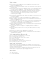
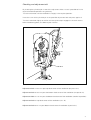
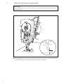
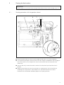
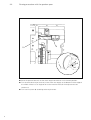
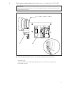
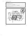
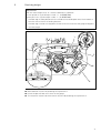
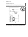
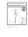
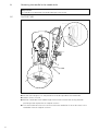
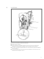
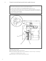
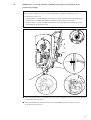
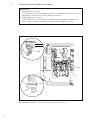
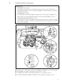
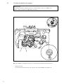
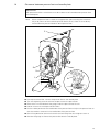
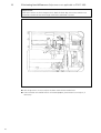
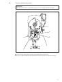
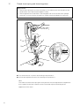
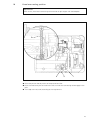
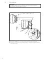
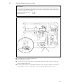
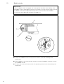
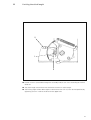
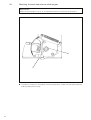
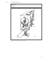
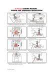
481
483
SERVICE MANUAL
296-12-17 437
Justieranleitung engl.
06.09
Notes on safety
● The machine must only be operated in full knowledge of the instruction book and by
persons with appropriate training.
● Before commissioning the machine also read the motor manufacturer’s safety notes and
instruction manual.
● The machine must only be used for the purpose intended. It must not be operated without
the safety devices it is equipped with; all valid safety regulations must be adhered to.
● When gauge parts are exchanged (e.g. needle, presser foot, needle plate, feed dog and
bobbin), during threading, when the workplace is left, and during service work, the
machine must be isolated from the mains by switching off the main switch or
disconnecting the mains plug.
● On mechanically operated clutch motors without start inhibitor it is necessary to wait until
the motor has stopped.
● Daily servicing work must only be carried out by persons with appropriate training.
● Repairs and special maintenance work must only be carried out by trained technicians or
persons with appropriate training.
● For service or repair work on pneumatic systems the machine must be disconnected from
the compressed air supply system. The only exceptions to this are adjustments and
function checks carried out by appropriately trained technicians.
● Work on the electrical equipment must only be carried out by electrical engineers or other
appropriately trained technicians.
● It is not permitted to work on live parts. For exceptions please see the EN 50 110
regulations.
● Conversions or changes to the machine must only be made on adherence to all safety
regulations.
● For repairs, only replacement parts approved by us must be used.
● The sewing head must not be operated until it is ascertained that the whole sewing unit
corresponds to EC-regulations.
Tools, gauges and other adjustment aids
● 1 set of screwdrivers with blades from 2 to 10 mm wide
● 1 set of spanners from 7 to 14 mm wide
● 1 set of hexagonal allen keys ranging from 1.5 to 6 mm
● 1 wrench, 22 mm wide
● 1 metal ruler (part No. 08-880 218-00)
● 1 cylindrical pin (5 mm in diameter), part No. 13-030 341-05
● 1 adjustment gauge, part No. 61-111 642-19
Notes on the service manual
All the adjustments in this service manual apply for a completely mounted machine. No
mention is made of the machine covers that occasionally have to be screwed off and back on
for testing and adjustment purposes.
The screws and nuts in brackets ( ) are for the attachment of machine parts that must be
loosened before the adjustments and tightened up again afterwards.
Abbreviations
t.d.c = top dead center
b.d.c. = bottom dead center
2
Checking and adjustment aid
By inserting the cylindrical pin in one of the adjustment holes 1 to 6 it is possible to fix the
required needle bar positions very precisely.
Turn the handwheel until the needle bar is roughly in the required position.
Insert the 5 mm thick cylindrical pin in the specified adjustment hole and press against it.
Turn the handwheel slightly to and fro until the cylindrical pin engages in the crank recess
behind the bearing plate, thus blocking the machine.
6
3
4
1
5
Adjustment hole 1 = 0.6 mm past top dead center of the needle bar (0.6 past t.d.c.).
Adjustment hole 3 = 0.6 mm past the bottom dead center of the needle bar (0.6 past b.d.c).
Adjustment hole 4 = 1.8 mm past the bottom dead center of the needle bar (needle rise position).
Adjustment hole 5 = top dead center of the needle bar (t.d.c. N).
Adjustment hole 6 = 4 mm past bottom dead center of needle bar (4 past b.d.c).
3
1
Preliminary adjustment of needle height
Requirement
With the needle bar at b.d.c. there must be a clearance of 16.5 mm between needle holder
and needle plate.
2
1
16,5 mm
● Move needle bar 1 (screw 2) according to the requirement. Make sure that, when looking
in the feed direction, the needle retaining screw points to the right.
4
2
Zeroing the feed motion
Requirement
The feed dog must not move when turning the handwheel with the stitch length set at “0”.
2.1
Zeroing procedure with the gearbox closed
6
8
7
8 mm
5
2
1
3
4
● Raise the presser foot and set the stitch length control lever 1 at its lowest position.
● Turn eccentric bushing 2 (screw 3) so that mark 4 is roughly at the bottom and the edge of
the milled surface is at an angle of 45° to the machine front (for final adjustment see
section 23).
● nsert an allen key in one of the holes in collar 5. Use the allen key to hold the shaft in
position.
● Rotate the handwheel and at the same time turn shaft 6 (screw 7) with the allen key
according to the requirement. Remember that in the PFAFF 483 there must be a
clearance of 8 mm between the bearing bush and actuating crank 8.
5
2.2
Zeroing procedure with the gearbox open
5
6
2
1
3
4
● Raise the presser foot and set the stitch length control lever 1 at its lowest position.
● Turn eccentric bushing 2 (screw 3) so that mark 4 is roughly at the bottom and the edge of
the milled surface is at an angle of 45° to the machine front (for final adjustment see
section 23).
● Turn crank 5 (screw 6) according to the requirement.
6
3
Zeroing the needle feed motion (Adjustment not applicable to Pfaff 483)
Requirement:
With the stitch length control set at “0” the needle bar should make no feed motion when
the handwheel is turned.
1
2
3
● Adjust needle feed regulating crank 1 (screw 2) according to the requirement.
Adjustment aid:
Insert a screwdriver in needle feed driving crank 3 - it must remain still when the
handwheel is turned.
7
4
Feed lifting motion
Requirement
With the stitch length set at “0”
the feed dog should be at t.d.c. when the needle bar is at a position 0.6 mm past b.d.c
(cylindrical pin in hole “3”; for PFAFF 481)
or 0.6 mm past t.d.c (cylindrical pin in hole “1”; for PFAFF 483).
In this position, the notch in feed lifting eccentric 1 should be positioned perpendicularly
below the center of the shaft.
3
1
2
● Turn feed lifting eccentric 1 (screws 2) according to the requirement.
8
5
Feed dog height
Requirement
With the stitch length set at “0” and the needle bar at a position
0.6 mm past b.d.c (cylindrical pin in hole “3”, for PFAFF 481)
and 0.6 past t.d.c. (cylindrical pin in hole “1”; for PFAFF 483)
1. the feed dog must be positioned in the middle of the needle plate slots when looked at
from the side as well as in feeding direction.
2. the feed dog must be at its top point of reversal and must contact the gauge throughout
its entire length.
3
1
1
3
5
4
6
X
=
X
2
● Move feed bar 1 (screw 2) according to requirement 1.
● Lower the presser foot until it rests on the gauge.
● Turn eccentric 3 (screw 4) and eccentric 5 (screw 6) according to requirement 2.
9
6
Feed driving motion
Requirement
With the longest stitch length set and
the needle bar at 0.6 mm past b.d.c. (cylindrical pin in hole “3”; for PFAFF 481)
the needle bar at 0.6 mm past t.d.c. (cylindrical pin in hole “1”; for PFAFF 483)
the feed dog should not move when the reverse-feed control is moved up and down.
3
1
2
1
● Turn feed driving eccentric 1 (screws 2) according to the requirement. Make sure that the
notch in the feed driving eccentric is visible.
10
7
Timing the needle feed motion (Adjustment not applicable to PFAFF 483)
Requirement
Both the needle bar and the feed dog should remain motionless when reverse-feed
control 3 is moved up and down with the machine set for its longest stitch and the
needle bar set 0.6 mm past its b.d.c. (cylindrical pin in hole “3”).
3
2
1
3
4
● Turn feed driving eccentric 1 (screws 2) according to the requirement making sure that the
notch in feed driving eccentric 1 points to the front.
Adjustment aid:
For easier checking insert a screwdriver in driving crank 4.
11
8
Centering the needle in the needle hole
Requirement
The needle must penetrate the needle hole right in the center.
8.1
For PFAFF 481
1
2
3
● Set the stitch length at “0” and position the needle right above the needle hole.
● Loosen screws 1 and 2.
● Position needle bar frame 3 both lengthwise and crosswise of the sewing direction
according to the requirement and tighten screw 1.
● Turn the handwheel a few turns to ensure that the needle bar is not under stress in the
needle bar frame and tighten screw 2.
12
8.2
For PFAFF 483
1
2
4
3
● Position the needle bar just above the needle hole.
● Loosen screws 1, 2 and 3.
● Position needle bar frame 4 both lengthwise and crosswise of the sewing direction
according to the requirement and tighten screw 2 just lightly and screw 3 firmly.
● Turn screw 1 to move the guide pin behind this screw towards the eye of the needle bar
frame and tighten it.
● Turn the handwheel a few turns to ensure that the needle bar is not under stress in the
needle bar frame and tighten screw 2.
13
9
Eccentric hook shaft bearing and hook-to-needle clearance
Requirement
1. The notch in bearing 3 (see arrow) must be visible from below.
There must be a slight but still noticeable play between gears 5 and 7.
2. With the hook set lightly against spin disc 4 and the hook point opposite the center line
of the needle, there must be clearance of less than 0.1 mm between the hook point and
the clearance cut of the needle.
3. Gear 5 must be flush with gear 7.
1
0,1 mm
4
2
7
3
6
5
● Loosen screws 1 and 2.
● Turn bearing 3 according to requirement 1.
● Set the hook lightly against spin disc 4, shift bearing 3 - without turning it - according to
requirement 2 and tighten screws 1 and 2.
● Position gear 5 (screws 6) according to requirement 3.
14
10
Needle rise, final adjustment of needle bar height and bobbin case
positioning finger
Requirement
With the stitch length set at “0” and the needle bar at a position 1.8 mm past b.d.c.
(cylindrical pin in hole “4”)
1. the hook point must be opposite the center line of the needle and the top edge of the
needle eye must be 0.8 mm below the bottom edge of the sewing hook.
2. there must be a clearance of 0.5 mm between the lug of positioning finger 3 and the
inside edge of the positioning slot.
4
0,8 mm
2
3
0,5 mm
1
● Adjust the hook (screws 1) without shifting it and the needle bar (screws 2) without turning
it according to requirement 1.
● Set lug of positioning finger 3 into the slot in the bobbin case base; adjust and fix it
according to requirement 2.
15
11
Vertical position of bobbin case opener
Requirement
1. Small hook (481 and 483)
At the left point of reversal of bobbin case opener 3 the bobbin case opener finger must
be roughly on one level with the lug of bobbin case base 4.
2. Large hook (481G and 483G)
At the left point of reversal of bobbin case opener 3 the top edge of the bobbin case
opener finger must be 0.5 mm above the bottom edge of bobbin case cam 5.
4
3
2
1
5
0,5 mm
3
● Turn bobbin case base 1 (screw 2) accoring to requirements 1 and 2.
16
12
Position of bobbin case opener
Requirement
1. Small hook (481 and 483)
With bobbin case opener 3 in its left point of reversal there must be a clearance of
approx. 0.8 mm between the front edge of the bobbin case opener finger and the edge
of bobbin case base 6.
2. Large hook (481 and 483)
At the left point of reversal of bobbin case opener 3 the front edge of the bobbin case
opener finger must be roughly 0.6 mm behind the front edge of bobbin case cam 7.
3. Large hook and small hook (481 and 483)
At the left point of reversal of bobbin case opener 3 there must be a clearance of roughly
0.3 mm between bobbin case base 6 and positioning finger 8 and stop screw 1 must be in
contact with stop pin 5.
6
0,8 mm
3
5 4
1
2
1
0,3 mm
8
7
0,6 mm
3
6
3
● Loosen screw 1. Then loosen screw 2 so that bobbin case opener 3 is still held in position.
● Adjust bobbin case opener 3 according to requirements 1 and 2.
● Turn bobbin case opener 3 according to requirement 1 and tighten screw 2.
● Set fixing collar 4 against bobbin case opener 3 and stop pin 5 and tighten screw 1.
17
13
Timing the bobbin case opener
Requirement
In needle bar position 1.8 mm past b.d.c. (cylindrical pin in hole “4”) bobbin case
opener finger must be at its right point of reversal.
4
3
1
2
● Adjust bobbin case opener eccentric 1 (screws 2) according to the requirement.
Adjustment aid:
To facilitate checking insert a screwdriver in the slot of bobbin case opener 3.
18
14
Clearance between presser foot and needle plate
Requirement
With presser bar lifter 1 raised there must be a clearance of 5 mm between presser foot
and needle plate.
Note:
When the presser foot is raised to its top position upon actuating the knee lever
fully or by means of the automatic presser foot lift -910/.. there must not be any
contact between presser foot bush 6 and presser foot.
2
4
3
5
1
10 mm
6
5 mm
● Lower presser bar lifter 1 to rest the presser foot on the needle plate.
● Turn out regulating screw 2 to lower the pressure on the presser bar.
● Place the 5-mm-thick blade of the gauge under the presser foot fulcrum.
● Loosen screw 3 and raise presser bar lifter 1.
● Let the needle penetrate the needle hole of the presser foot and adjust the presser foot so
that the needle is centered in the needle hole of the presser foot.
● Press lifting bracket 4 downwards onto the raised lifting lever 5 and tighten screw 3.
● Remove the gauge and lower the presser foot onto the needle plate.
19
15
Eliminating feed differences (Adjustment not applicable to PFAFF 483)
Requirement
With the machine set for its longest stitch, both the feed dog and and the needle must
make feed strokes of the same length when the handwheel is turned.
1
2
● Shift hinge stud 1 (nut 2) to adjust the feed stroke of the needle feed.
● Check whether the needle feed is still zeroed properly (see Section 3) and adjust, if
necessary.
20
16
Tension release mechanism
Requirement
When presser bar lifter 1 is raised both tension discs must be at least 0.5 mm apart.
0,5 mm
3
1
2
● Adjust tension release lever 2 (screw 3) according to the requirement.
● Lower the presser foot onto the needle plate. Now the tension must be fully activated.
21
17
Thread check spring and thread regulator
Requirement
1. Thread check spring 3 must have moved by its full stroke by the time the point of the
needle enters the material (stroke approx. 7 mm).
2. Thread regulator 4 must be fixed in the elongated hole so that thread check spring 3
moves by 1 mm by the time the hook has widened the thread loop to its maximum.
5
4
2
3
1
7 mm
● Turn thread tension 1 (screws 2) according to requirement 1.
● Shift thread regulator 4 (screws 5) according to requirement 2.
Note:
The stroke of thread check spring 3 and the position of thread regulator 4 are dependent
on the type of thread and material used and should be adjusted according to the
appearance of the seam.
22
18
Knee lever resting position
Requirement
When at rest, knee lever connecting rod 2 must be at right angles with the bedplate.
2
4
3
1
● Raise the presser foot by means of the presser bar lifter.
● Push the knee lever joint on knee lever shaft 1 and let the connecting rod 2 engage in the
joint.
● Turn stop screw 3 (nut 4) according to the requirement.
23
19
Knee lever play
Requirement
When the presser foot is resting on the needle plate, there must be a clearance of
1.3 mm between lifting lever 3 and lifting piece 4.
4
2
1,3 mm
1
3
● Position the needle at its b.d.c. and let the presser foot down on the needle plate.
● Turn crank 1 (screws 2) according to the requirement. Make sure the vertical knee lever
shaft has no end play.
24
20
Adjusting the knee lever motion
Requirement
When the knee lever is pushed by the full amount of its travel, there must be a clearance
as indicated in the table below between presser foot and needle plate and the presser bar
lifter should drop by its own weight.
Version A and subclass -731/..:
Versions B and C:
7 mm
9 mm
7/9 mm
1
2
● Turn stop screw 1 (nut 2) out a few turns.
● Raise the presser bar lifter.
● Place the 7-mm-thick or the 9-mm-thick blade of the gauge under the presser foot and
lower the presser bar lifter.
● Push the knee lever until a noticeable resistance is felt; the presser foot must not yet lift
off the gauge. First turn in stop screw 1 (nut 2) fully, then back out by half a turn.
25
21
Bobbin winder
Requirement
When the bobbin winder is engaged, the winder spindle should be driven reliably; when
the bobbin winder is disengaged, however, drive wheel 1 must not contact friction wheel 5.
The bobbin winder should stop automatically when the thread wound on the bobbin
has reached a point about 1.0 mm below the bobbin rim.
5
2
1
1 mm
3
4
● Switch on the bobbin winder and adjust drive wheel 1 (screw 2) according to the
requirement.
● Place a bobbin on the winder spindle, thread the machine for bobbin winding and switch
on the bobbin winder.
● To adjust the amount of thread wound shift regulating stud 3 (screw 4) according to the
requirement.
26
22
Limiting the stitch length
2
1
3
● Loosen screw 1 (accessible through the assembly hole) or turn it out according to the limit
to be set.
● Set stitch length control lever 2 at the desired maximum stitch length.
● Set limiting angle 3 from above against control lever 2 and fix it (in the desired position) by
tightening screw 1 in either the lower or the upper hole.
27
23
Matching forwards and reverse stitch lengths
Requirement
When the stitch length is set at “3” the forwards feed must match the reverse feed.
1
2
● Turn bush 1 (screw 2) in accordance with the requirement. Make sure that the eccentricity
of bush 1 points downwards.
28
24
Presser foot pressure
Requirement
Proper feeding of the material must be ensured even at top sewing speed. There must
Contents
1
● Turn screw 1 according to the requirement.
29
Contents
Checking and adjustment aid ..................................................................................... 3
30
1
Preliminary adjustment of the needle height .............................................................. 4
2
Zeroing the feed motion .......................................................................................... 5-6
3
Zeroing the needle feed motion (not applicable to PFAFF 483) .................................. 7
4
Feed lifting motion ..................................................................................................... 8
5
Feed dog height ......................................................................................................... 9
6
Feed driving motion ................................................................................................. 10
7
Timing the needle feed motion (not applicable to PFAFF 483) ................................. 11
8
Centering the needle in the needle hole .............................................................. 12-13
9
Eccentric hook shaft bearing and hook-to-needle clearance ..................................... 14
10
Needle rise, final adjustment of needle height and bobbin case positioning finger .. 15
11
Vertical position of bobbin case opener .................................................................... 16
12
Position of bobbin case opener ................................................................................ 17
13
Timing the bobbin case opener ................................................................................ 18
14
Clearance between presser foot and needle plate ................................................... 19
15
Eliminating feed differences (not applicable to PFAFF 483) ..................................... 20
16
Tension release mechanism .................................................................................... 21
17
Thread check spring and thread regulator ................................................................ 22
18
Knee lever resting position ....................................................................................... 23
19
Knee lever play ......................................................................................................... 24
20
Adjusting the knee lever motion .............................................................................. 25
21
Bobbin winder .......................................................................................................... 26
22
Limiting the stitch length .......................................................................................... 27
23
Matching forwards and reverse stitch lengths ......................................................... 28
24
Presser foot pressure .............................................................................................. 29
Note
Hans-Geiger-Str. 12 - IG Nord
D-67661 Kaiserslautern
Telefon: +49 - 6301 3205 - 0
Telefax: +49 - 6301 3205 - 1386
E-mail:
[email protected]
Gedruckt in der BRD / Printed in Germany / Imprimé en la R.F.A. / Impreso en la R.F.A
© PFAFF Industriesysteme und Maschinen AG 2009, PFAFF is the exclusive trademark of VSM Group AB.PFAFF Industriesysteme und Maschinen AG is an authorized licensee of the PFAFF trademark.
PFAFF Industriesysteme
und Maschinen AG