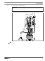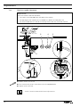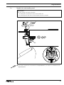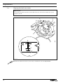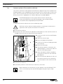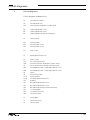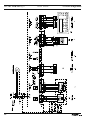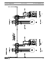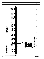
1
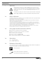
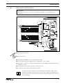
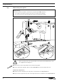
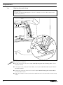
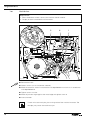
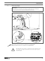
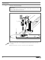
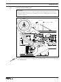
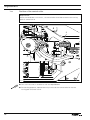
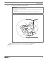
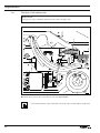
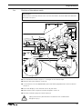
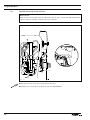
3371-1/..
SERVICE MANUAL
This service manual applies to machines
from serial number 2 780 933 and software
version 0335/022 onwards
296-12-18 982/002
Justieranleitung engl. 01.11
The reprinting, copying or translation of PFAFF Service Manuals, whether in whole or
in part, is only permitted with our previous authorization and with written reference
to the source.
PFAFF Industriesysteme
und Maschinen AG
Hans-Geiger-Str. 12 - IG Nord
D-67661 Kaiserslautern
Index
Contents ................................................................................ Page
1
1.01
1.02
1.03
1.04
1.05
1.06
1.07
1.08
1.09
1.10
1.11
1.12
1.13
1.14
1.15
1.16
1.17
1.18
1.19
1.20
1.21
1.22
1.23
1.24
1.25
1.26
Adjustment ........................................................................................................................... 4
1.27
1.28
1.29
1.30
1.31
1.32
1.33
1.34
Work clamp initiator ............................................................................................................. 29
2
Notes on adjustment ............................................................................................................. 4
Tools, gauges and other accessories for adjusting ............................................................... 4
Abbreviations ......................................................................................................................... 4
Explanation of the symbols .................................................................................................... 4
Basic position of the machine ................................................................................................ 5
Work clamp zero point ........................................................................................................... 6
Aligning the work clamp ........................................................................................................ 8
Hook driver........................................................................................................................... 10
Preadjusting the needle height ............................................................................................ 11
Hook-to-needle clearance .................................................................................................... 12
Needle rise and needle guard .............................................................................................. 13
Aligning the hook race cover................................................................................................ 14
Work clamp height ............................................................................................................... 15
Position of the thread wiper ................................................................................................. 16
Position of the control cam .................................................................................................. 17
Position of the control roller ................................................................................................. 18
Position of the drive shaft of the thread trimmer ................................................................. 19
Aligning the stop plate ......................................................................................................... 20
Adjusting the trimmer solenoid............................................................................................ 21
Adjusting the engaging lever ............................................................................................... 22
Position of the thread catcher and knife............................................................................... 23
Position of the release trip ................................................................................................... 24
Position of the release catch ................................................................................................ 25
Needle thread tension release ............................................................................................. 26
Thread check spring and thread regulator ............................................................................ 27
Bobbin winder drive wheel .................................................................................................. 28
Changing the work clamp .................................................................................................... 30
Cold start ............................................................................................................................. 31
Internet update of the machine software ............................................................................ 32
List of parameters ................................................................................................................ 33
Error messages on the display............................................................................................. 40
Sewing motor errors ............................................................................................................ 42
OTE-errors ............................................................................................................................ 42
Circuit diagrams ................................................................................................................. 43
Adjustment
1
Adjustment
Please observe all notes from Chapter 1 Safety of the instruction manual!
In particular care must be taken to see that all protective devices are refitted
properly after adjustment, see Chapter 1.06 Danger warnings of the instruction manual!
If not otherwise stated, the machine must be disconnected from the electrical
power supply. Danger of injury due to unintentional starting of the machine!
1.01
Notes on adjustment
All following adjustments are based on a fully assembled machine and may only be carried
out by expert staff trained for this purpose.
Machine covers, which have to be removed and replaced to carry out checks and adjustments, are not mentioned in the text.
The order of the following chapters corresponds to the most logical work sequence for
machines which have to be completely adjusted. If only specific individual work steps are
carried out, both the preceding and following chapters must be observed.
Screws, nuts indicated in brackets ( ) are fastenings for machine parts, which must be
loosened before adjustment and tightened again afterwards.
1.02
Tools, gauges and other accessories for adjusting
● Screwdrivers with blade width from 2 to 10 mm
● Spanners (wrenches) with jaw width from 7 to 14 mm
● 1 set Allen keys from 1.5 to 6 mm
● 1 Metal rule (part No. 08-880 218-00)
● 1 machine zero point gauge, part number 61-111 637-08
1.03
Abbreviations
t.d.c. = top dead centre
b.d.c. = bottom dead centre
1.04
Explanation of the symbols
In this adjustment manual, symbols emphasize operations to be carried out or important information. The symbols used have the following meaning:
Note, information
Service, repair, adjustment, maintenance
(work to be carried out by qualified staff only)
4
Adjustment
1.05
Basic position of the machine
Requirement
After being switched on the machine should position approx. 3 – 4 mm before t.d.c.
take-up lever.
2
3,5 mm
1
3
2
Fig. 1 - 01
● Switch on the machine.
● Press the TE key.
● Select parameter 605 with the corresponding +/- key.
● Press pedal forwards once briefly (machine positions in t.d.c. needle).
● Hold clutch 1 (screws 2) and bring the needle bar into the appropriate position by turning
the balance wheel.
● Press pedal forwards again to re-check the position set.
● Conclude the adjustment by operating the TE key.
The distance from the clutch 1 to the motor plate should be 3.5 mm. In the
direction of rotation the second screw of the clutch section 3 should be on the
surface of the motor shaft. The clutch section 1 should be touching the 0-ring of
the axial bearing.
5
Adjustment
1.06
Work clamp zero point
Requirement
After the machine ahs been switched on and parameter "608" selected,
1. the needle should be centred to the hole in the adjustment gauge,
2. the switch lugs 2 and 4 should be centred to the respective initiator.
1
3
2
5
4
Fig. 1 - 02
When removing the work clamp holder, take care that the ball bearings in the
arm support do not drop out !
● Remove the work clamp holder and the lower feed plate .
● Screw adjustment gauge 1 (part no. 61-111 637-08) to the work clamp drive unit.
Preliminary adjustment
● Move the work clamp drive unit by hand in accordance with requirement 1.
● Adjust switch lug 2 (screw 3) and switch lug 4 (screw 5) in accordance with requirement 2.
6
Adjustment
Fine adjustment
● Switch on the machine.
● In the input mode, select parameter "608", see Chapter 11.03 Parameter input in the
instruction manual.
● If necessary, enter the access code, see Chapter 11.04.01 Entering the access code in
the instruction manual.
● With the corresponding plus/minus key move the work clamp drive unit in accordance
with requirement 1, also see Chapter 11.03 Parameter input.
● Switch off the machine.
● Remove adjustment gauge 1.
● Fit the lower feed plate and work clamp holder.
If, during the fine adjustment, the setting is ± 5 increments above or below the
value in X- and Y-direction, the setting should be checked again in accordance
with requirement 2.
7
Adjustment
1.07
Aligning the work clamp
Requirement
The work clamp should be aligned in "X" and "Y" direction, so that it does not touch the
needle during sewing.
2
3
X
1
Y
Fig. 1 - 03
● Switch on the machine.
● Set the sewing area size (see Chapter 9.07 Adjusting the size of sewing area in the instruction manual)
● In the input mode, select parameter "610", see Chapter 11.03 Parameter input in the instruction manual
● If necessary, enter the access code, see Chapter 11.04.01 Entering the access code in
the instruction manual.
● Align work clamp 1 (screw 2) so that the needle hole 3 is in the centre of the work clamp
cutout.
8
Adjustment
Checking the "Y-direction"
● To check this adjustment, move along the maximum set sewing area size in "Y-direction"
by pressing the corresponding plus/minus keys (readjust if necessary).
● Call up parameter "609".
Checking the "X-direction"
● Move along the maximum set sewing area size in "X-direction" by pressing the
corresponding plus/minus keys.
● If necessary adjust the position of work clamp 1 by entering a correction value "X" with
the corresponding plus/minus keys in "X-direction" in accordance with the requirement.
● Conclude the input.
When using the max. sewing area size (X=40mm, X =20 mm), the correction
value under parameter "609" must be set at "0".
9
Adjustment
1.08
Hook driver
Requirement
1. When the balance wheel is turned, the machine should not bind.
2. The play of catch 7 should be less than 0.1 mm.
6
3
1
7
5
2
4
Fig. 1 - 04
● Remove the hook.
● Loosen screws 1, 2 and 3 (remove motor 4).
● Move the eccentric shaft 5 in accordance with requirement 1 and twist it in accordance
with requirement 2.
● Tighten screws 1 and 3.
● Move adjustment ring 6 against the metal edge and tighten screw 2.
● Insert the hook.
If catch 7 has too much play, the running noise of the machine increases. Too
little play may cause the machine to jam.
10
Adjustment
1.09
Preadjusting the needle height
Requirement
With the needle bar in b.d.c., the upper marking on the needle bar 1 should be flush with
the lower edge of the needle bar bush.
2
1
Fig. 1 - 05
● Adjust needle bar 1 (screw 2) in accordance with the requirement.
11
Adjustment
1.10
Hook-to-needle clearance
Requirement
With the needle at 2.4 mm after BDC,
1. the hook 5 should be 0.05 – 0.1 mm behind the needle,
2. the top edge of the needle eye must be 0.8 mm below the hook point and
3. the distance between the needle and the tip of the hook race should be 7.5 mm.
3
4
2
0,8 mm
0,05 - 0,1 mm
1
0,05 - 0,1 mm
7,5 mm
5
Fig. 1 - 06
● Loosen screws 1, 2 and 3.
● Turn the eccentric pin 4 in accordance with the requirements.
● Tighten screws 2 and 3.
Screw 1 remains loosened for further adjustments.
12
Adjustment
1.11
Needle rise and needle guard
Requirement
With the needle at 2.4 mm after BDC,
1. the hook point should be centred to the needle and
2. the needle guard (see arrow) should slightly touch the needle.
2
1
Fig. 1 - 07
● Turn catch 1 (screw 2) in accordance with requirement 1, or move it in accordance with
requirement 2.
13
Adjustment
1.12
Aligning the hook race cover
Requirement
The needle should be centred to cutout B and the rear side of the needle flush to the
imaginary line A.
2
1
B
A
1
Fig. 1 - 08
● Move the hook race cover 1 (screws 2) in accordance with the requirement.
14
2
Adjustment
1.13
Work clamp height
Requirement
1. The work clamp should be 13 mm above the upper edge of the needle plate.
2. Both halves of the work clamp should be parallel to each other.
5
4
1
1
3
13 mm
2
Fig. 1 - 09
● Turn lever 1 (nut 2 and screw 3) in accordance with requirement 1.
● Move lift plate 4 (screws 5) in accordance with requirement 2.
After aligning the work clamp, it is imperative to check the position of the
thread wiper, see Chapter 1.14. Position of the thread wiper! Danger of
needle breakage!
15
Adjustment
1.14
Position of the thread wiper
Requirement
When the thread wiper is centred to the needle, its lower edge should be 14 – 15 mm
above the upper edge of the needle plate.
2
1
14 - 15 mm
Fig. 1 - 10
● Bring the thread wiper 1 into the appropriate position by operating the work clamp
manually.
● Move thread wiper 1 (screw 2) in accordance with the requirement.
16
Adjustment
1.15
Position of the control cam
Requirement
1. The markings on control cam 1 and arm shaft 3 should correspond with each other.
2. The outer edge of control cam 1 should be at a distance of 32.5 mm from the metal
surface of the case.
32,5 mm
3
2
1
Fig. 1 - 11
● Turn control cam 1 (screw 2) in accordance with requirement 1, or move it in accordance
with requirement 2.
17
Adjustment
1.16
Position of the control roller
Requirement
When the needle bar is at its b.d.c., the control roller should be centred to the running
path of control cam 2.
3
2
4
1
Fig. 1 - 12
● Turn screw 3 (nut 4) in accordance with the requirement.
● For checking purposes, operate lever 1 by hand to let the control roller fall into the
running path of control cam 2.
18
Adjustment
1.17
Position of the drive shaft of the thread trimmer
Requirement
When the thread trimmer is in its basic position, shaft 1 should be flush with the metal
edge of the machine case.
1
2
3
Fig. 1 - 13
● Move shaft 1 (screws 2 and 3) in accordance with the requirement.
19
Adjustment
1.18
Aligning the stop plate
Requirement
When the thread trimmer is in its basic position, there should be a clearance of 0.3 mm
between lever 3 and plate 1.
3
0,3 mm
1
2
Fig. 1 - 14
● Move plate 1 (screws 2) in accordance with the requirement.
20
Adjustment
1.19
Adjusting the trimmer solenoid
Requirement
When the thread trimmer is in its neutral position, solenoid 1 should be at a distance of
5 mm from the case.
1
2
5 mm
Fig. 1 - 15
● Turn nut 1 (nut 2) in accordance with the requirement.
21
Adjustment
1.20
Adjusting the engaging lever
Requirement
When the thread trimmer is in its neutral position, pin 3 should be at a distance of 0.5 mm
from release trip 4.
3
4
1
2
0,5 mm
Fig. 1 - 16
● Move lever 1 (screws 2) in accordance with the requirement.
22
Adjustment
1.21
Position of the thread catcher and knife
Requirement
When the machine is in its basic position
1. the tip of the thread catcher 1 should be at a distance of 4.5 mm from the centre of the
needle hole.
2. The blade of knife 3 should be at distance of 0.5 mm from the needle plate insert.
0,5 mm
1
2
3
4,5
mm
4
Fig. - 17
● Adjust thread catcher 1 (screw 2) in accordance with requirement 1.
● Adjust knife 3 (screws 4) in accordance with requirement 2.
23
Adjustment
1.22
Position of the release trip
Requirement
The slots of trip 1 should be touching screws 2 on the right side.
1
2
Fig. 1 - 18
● Move trip 1 (screws 2) in accordance with the requirement.
If the needle thread is too short after trimming, trip 1 can be slightly readjusted.
24
Adjustment
1.23
Position of the release catch
Requirement
When lever 6 is touching release catch 7, there should be a distance of 0.3 mm between
drive lever 5 and pin 1.
1
3
6
2
4
1
7
6
5
Fig. 1 - 19
● Turn the balance wheel until pin 1 is no longer on the release trip 2.
● Release spring 3 and loosen screws 4.
● In accordance with the requirement, place the feeler gauge between the drive lever 5
and pin 1.
● Push lever 6 lightly in the direction shown by the arrow.
● Move release catch 7 against lever 6 and tighten screws 4.
● Remove the feeler gauge and attach spring 3.
Spring 3 should only be released and attached with suitable tools!
Danger of injury!
25
Adjustment
1.24
Needle thread tension release
Requirement
After thread trimming the distance X between tension discs 3 should be 0.6 – 0.8 mm for
normal materials and 0.8 – 1.0 mm for heavy materials.
1
2
3
X
Fig. 1 - 20
● Bring the machine into the cutting position by hand.
● Move lever 1 (screw 2) in accordance with the requirement.
26
Adjustment
1.25
Thread check spring and thread regulator
Requirement
1. The thread check spring 1 should have a 6 – 8 mm stroke.
2. Screw 4 should be positioned in the centre of the slot of thread regulator 3.
3
4
5
1
2
Fig. 1 - 21
● Adjust thread check spring 1 (screw 2) in accordance with requirement 1.
● Move thread regulator 3 (screw 4) in accordance with requirement 2.
Turn pin 5 to adjust the thread spring resistance. All settings of the thread check
spring 1 depend on the material and might have to be corrected to achieve the
desired result.
27
Adjustment
1.26
Bobbin winder drive wheel
Requirement
1. The should be a distance of approx. 40 mm between drive wheel 1 and the metal
edge of the machine case.
2. When the bobbin winder is switched on, its friction wheel should be driven by drive
wheel 1. When the bobbin winder is switched off, drive wheel 1 must not touch the
friction wheel of the bobbin winder.
1
2
40 mm
Fig. 1 - 22
● Adjust drive wheel 1 (screw 2) in accordance with the requirements.
28
Adjustment
1.27
Work clamp initiator
Requirement
When the work clamp is lowered and shortly before lever 5 in the machine arm touches
stop 6, the initiator should switch on (input "3" parameter "601" is positioned at "off").
2
4
3
1
6
5
Fig. 1 - 23
● Switch on the machine and press the "TE" key.
● Lower the work clamp by pressing the "tacting forwards" key.
● With the clamp in this position, press the "TE" key.
● In the input mode, select parameter "601", see Chapter 11.03 Parameter input in the
instruction manual.
● Select input "3" with the corresponding plus/minus key.
● If necessary, enter the access code, see Chapter 11.04.01 Entering the access code in
the instruction manual.
● Move cam switch 1 by hand and check the ON/OFF switch position on the display.
● Adjust support 2 (screws 3) and cam switch 1 (screws 4) in accordance with the requirement.
● Switch off the machine.
29
Adjustment
Changing the work clamp
X
1.28
Y
Fig. 1 - 24
● Measure the cutout of the new work clamp in X- and Y-direction.
● Adjust the sewing area size as described in Chapter 9.07 of the instruction manual.
● Fit the new work clamp and align it in as described in Chapter 15.07.
● Select the seam program to match the work clamp cutout (see Chapter 9.06 of the instruction manual).
● Check the seam program by tacting (see Chapter 7.04 of the instruction manual).
If the actual size of the sewing area differs from the size entered, serious damage can be caused to the machine!
30
Adjustment
1.29
Cold start
When a cold start is carried out, the seam patterns 50 – 99 and all altered
parameter settings are deleted! The machine is reset to its condition on
delivery, the machine’s zero points remain unaffected.
● Switch on the machine.
● Select parameter "607" with the corresponding plus/minus keys.
● If necessary, enter the code, see Chapter 11.04.01 Entering the access code in the
instruction manual.
● With the corresponding plus/minus keys carry out the reset operation.
● Switch the machine off and on again after approx. 3 seconds.
31
Adjustment
1.30
Internet update of the machine software
The machine software can be updated with PFAFF flash programming. For this purpose the
PFP boot program and the appropriate control software for the machine type must be installed on a PC. To transfer the data to the machine, the PC and the machine control unit must
be connected with an appropriate null modem cable (part no. 91-291 998-91).
The PFP boot program and the control software of the machine type
can be downloaded from the PFAFF-homepage using the following path:
www.pfaff-industrial.de/pfaff/de/service/downloads
To update the machine software carry out the following steps:
While the machine software is being updated, no setting up, maintenance or
adjustment work may be carried out on the machine!
● Switch off the machine.
● Connect the PC (serial interface or appropriate USB-adapter) and the machine control unit
(RS232). To do so disconnect the plug of the control panel.
● Switch on the PC and start the PFP boot
program.
● Select the machine type.
● Press the "programming" button.
● Switch on the machine, keeping the boot
key 1 pressed.
1
● Press the "OK" button.
● The software update is carried out, the
update progress is shown on the bar display of the PFP boot program.
● When the update has been completed,
switch off the machine and end the PFP
boot program.
● End the connection between the PC and
the machine control unit and reconnect
the control panel to the machine control
unit.
Fig. 1 - 25
● Switch on the machine.
● A plausibility control is carried out and, if necessary, a cold start.
More information and assistance is at your disposal in the file "PFPHILFE.TXT",
which can be called up from the PFP boot program by pressing the "help"
button.
32
Adjustment
1.31
List of parameters
The parameter setting values my only be altered by appropriately trained staff!
Group Parameter
Gruppe Parameter
000
Description
Bedeutung
001
Maximum speed
This parameter is used to fix the max.
sewing speed (upper limit).
002
Sewing speed for start stitches
With this parameter the speeds for
the 5 start stitches are fixed.
Speed (spm) for start stitch no. 1
Speed (spm) for start stitch no. 2
Speed (spm) for start stitch no. 3
Speed (spm) for start stitch no. 4
Speed (spm) for start stitch no. 5
003
Locking/releasing seam patterns
This parameter is used to release (ON)
Setting
range
Set value
500 - 2700
2700
500 - 2700
500 - 2700
500 - 2700
500 - 2700
500 - 2700
500
900
2700
2700
2700
ON - OFF
ON
ON - OFF
1 - 9999
OFF
11
0-4
0
or lock (OFF) the individual seam
patterns (0 to 99) to be carried out in
the sewing mode.
004
Switch bobbin thread counter on/off
Standard value (pieces per bobbin)
In the sewing mode, the bobbin thread
counter counts the pieces sewn backwards from the standard value. If the
bobbin thread counter is
switched on, in the sewing mode a
signal is given when the value 0 is reached.
005
Sequence combination
This parameter is used to combine several sequences with each other.
0 = no combination
1 = C1 with C2
2 = C2 with C3
3 = C1 with C3
4 = C1 with C2 and C3
33
Adjustment
Group Parameter
Gruppe Parameter
000
34
Description
Bedeutung
Setting
range
Set value
006
Reversing after thread trimming
Reverse position [°]
With this parameter it is possible to
switch the automatic reversing function after thread trimming on or off. If
the reversing function is switched on,
the reverse position can be set by turning the balance wheel. The access
code is necessary for this adjustment.
ON - OFF
0 - 14
ON
11
007
Starting point = scale reference
point
With this parameter it is possible to
choose whether the scale reference
point is the starting point (ON) or the
zero point (OFF).
ON - OFF
OFF
008
Speed for the "winding" function
This parameter is used to fix the
speed for the winding operation.
200 - 2700
1500
009
Via zero point to starting point after
end of sequence
With this parameter it is possible to
choose that, after the end of the
sequence, the X-, Y-drive moves to the
seam starting point via the reference
initiators.
ON - OFF
OFF
010
Via zero point to starting point after
number of program cycles Number
of program cycles
With this parameter it is possible to
choose that, after a certain number of
program cycles, the X-, Y-drive moves
to the seam starting point via the reference initiators.
ON - OFF
1 - 100
OFF
011
Pedal mode
Switchover between level mode (0)
and flip flop mode (1).
0-1
0
012
Needle or balance wheel position
in degrees
0 - 360
11
Adjustment
Group Parameter
Gruppe Parameter
000
Description
Bedeutung
Setting
range
Set value
65 -166
107
013
NIS "needle in material" [°]
This parameter is used to set the NIS
signal. If the function is executed, the
position can be entered by turning the
balance wheel. If the position is altered, the result is a change in the point
of time when the carriage is moved.
The access code is necessary for this
adjustment.
014
Thread trimming speed [min-1]
This parameter is used to fix the
speed for thread trimming.
100 - 700
300
015
Reduced current for stepping motors
The reduction function of the holding
current at rest with closed work clamp
is switched on or off.
ON - OFF
ON
016
Key tone
The key tone, as reaction to a key on
the control panel being pressed, is
switched on or off. The double tone
for incorrect inputs always remains
switched on.
ON - OFF
ON
017
Clamp solenoid Operating time [10 ms]
The time, for which the solenoid is under full current, is entered.
5 - 100
10
018
Clamp solenoid duty-cycle [%]
At the end of the clamp solenoid operating time (Parameter "017") the solenoid is clocked. The relationship between duration of operation and nonoperation is entered here.
5 - 100
20
019
Thread trimming solenoid operating
time [10 ms]
The time, for which the solenoid is under full current, is entered.
5 - 100
25
020
Thread trimming solenoid duty-cycle
At present without a function
5 - 100
100
35
Adjustment
Group Parameter
Gruppe Parameter
000
100
36
Description
Bedeutung
Setting
range
Set value
021
Thread take-up lever t.d.c. [°]
The position for the t.d.c. thread takeup lever is entered here. If the function is executed, the position can be
set by turning the balance wheel. The
access code is necessary for this adjustment.
45 - 53
51
022
Thread trimming position (in relation to t.d.c. needle) [°]
The position, at which the thread trimming solenoid is switched on, is entered here. The adjustment is set by turning the balance wheel. The access
code is necessary for this adjustment.
180 - 253
180
023
Sewing area size X [1/10 mm]
To avoid mechanical collisions, the
sewing area size of the clamp in use
is entered. The control unit checks
the path and, if necessary, issues an
error message.
± 200
-100/ +100
024
Sewing area size Y [1/10 mm]
To avoid mechanical collisions, the
sewing area size of the clamp in use
is entered. The control unit checks the
path and, if necessary, issues an error
message.
± 100
-15/ +15
025
Thread wiper solenoid
operating time [10 ms]
026
Thread wiper solenoid, ratio on-time
to off-time in % (Duty-Cycle)
027
Basic position / loading point = zero
point
ON - OFF
OFF
101
Software version main processor
The software version of the main processor is displayed
0335/xxx
102
Software version sewing drive unit
The software version of the sewing
drive module is displayed.
V.xx
103
Software version control panel
The soft- and hardware version of the
control panel are displayed.
V.xxx/ H.xxx
Adjustment
Group Parameter
Gruppe Parameter
600
601
Description
Bedeutung
Setting
range
Set value
Display inputs
With this function the digital inputs
can be checked. "IN" shows the input
numbers (1 - 16). Under "VAL" the respective switch status is displayed.
IN
VAL
1
IN1,
programmable input 1
2
IN2,
programmable input 2
3
E3,
work clamp raised
4
5
6
7
8
9
10
11
12
13
14
15
16
602
Display special inputs
With this function it is possible to
check the special inputs pedal,
reference X (SM1) and reference Y
(SM2). "IN" shows the inputs (PED,
REFX, REFY). Under "VAL" the
respective switch status is displayed.
IN
VAL
PED
Pedal (speed control unit
-1; 0; +1; 2)
REFX Reference input X
REFY Reference input Y
37
Adjustment
Group Parameter
Gruppe Parameter
600
603
Description
Bedeutung
Setting
range
Set value
500 -2700
500
Connect outputs
With this function the outlets can be
connected. "OUT" shows the outlet
selected (1-16). Under "VAL" the
selected output is set (S) with the
plus/minus key (+), and reset (R) with
the plus/minus key. Interlocks are
checked. Non-assigned outlets are not
connected.
OUT
VAL
1
S/R
Solenoid for work
clamp open
2
S/R
3
S/R
Solenoid for
thread trimming
38
4
S/R
5
S/R
6
S/R
Program outlet
7
S/R
Program outlet
8
S/R
9
S/R
10
S/R
11
S/R
12
S/R
13
S/R
14
S/R
15
S/R
16
S/R
604
Move stepping motors
The stepping motors SM1 (X-axis) and
SM2 (Y-axis) are moved individually
with the respective plus/minus keys.
Interlocks are not checked.
605
Turn sewing motor
The sewing motor can be operated
with a selectable set speed by pressing the pedal. After the sewing motor
has been started, the current speed is
also displayed.
Adjustment
Group Parameter
Gruppe Parameter
600
Description
Bedeutung
606
Thread trimming sequence
The sequence for a complete thread
trimming cycle is started with the +/key (+) below CUT and below THR.
607
Cold start (RESET)
With this function the control unit
carries out a cold start (RESET) with
which the data is reset. After this function has been selected, the machine must be switched off and then on
again.
608
Setting zero points
With this function and the adjustment
gauge, the zero points for the X/Y-drive
unit can be set. (stepping motor correction values for the reference points
REFX, REFY). The access code is
required for this adjustment.
609
Setting the clamp centre X
This function is used to set the centre of the clamp in X-direction. When
entering the function, the machine
moves to the current clamp centre,
after which it is possible to move to
the right or left edge of the clamp,
depending on the set limits (param.
"023"). A correction can be made with
the plus/minus keys. The relocation value is displayed.
610
Setting the clamp centre Y
This function is used to help set the
centre of the clamp in Y-direction. After entering this function, the machine
moves to the current clamp centre,
after pressing a key to the front or the
rear limit (param. "024"). The clamp
must be shifted manually.
Setting
range
Set value
39
Adjustment
Group Parameter
Gruppe Parameter
600
Set value
Automatic clamp opening off
With this function the automatic opening of the clamp after thread trimming can be switched off. After the
machine has been switched off, the
automatic clamp opening function
is always activated.
ON - OFF
OFF
612
Test function continuous start
ON - OFF
OFF
The function groups and the functions
Programming the Function Keys P, P1P8 and C1-C3 can be released for manipulation (ON) or locked (OFF). If a function group is suppressed, its parameters cannot be changed until a valid access code has been entered. Once a
valid access code has been entered,
the suppression is cancelled until the
machine is switched off.
801
Right of access function group 000
ON - OFF
ON
802
Right of access function group 100
ON - OFF
ON
807
Right of access function group 600
ON - OFF
OFF
808
Right of access function group 700
ON - OFF
OFF
809
Right of access function group 800
ON - OFF
OFF
810
Right of access to keys "P",
"P1" - "P8" and "C1" - "C3"
ON - OFF
ON
811
Access code
This parameter is used to alter the access code. Upon delivery the
machine is set with the access code
"3371".
Error messages on the display
Following error messages are shown on the control panel display
40
Setting
range
611
800
1.32
Description
Bedeutung
ERROR: 1
Processor error STACK_OVERFLOW
ERROR: 2
Processor error STACK_UNDERFLOW
ERROR: 3
Processor error UNDEF_OPCODE
ERROR: 4
Processor error PROTECTION_FAULT
3371
Adjustment
ERROR: 5
Processor error ILLEGAL_WORD_OPERAND
ERROR: 6
Processor error ILLEGAL_INSTRUCTION
ERROR: 7
Processor error ILLEGAL_BUS_ACCESS
ERROR: 8
Processor error NMI
ERROR: 10
OTE (Sewing head recognition unit) not attached
ERROR: 11
OTE not programmed (new)
ERROR: 12
OTE check sum error
ERROR: 13
OTE header invalid
ERROR: 14
OTE user data invalid
ERROR: 30(#)
(OTE error see cap. 11.10)
ERROR: 31(#)
(Error Sewing motor see cap. 11.09)
ERROR: 50
Incorrect control panel
ERROR: 51
Incorrect machine class in OTE
ERROR: 52
Incorrect software for main drive
ERROR: 101
Mains voltage
ERROR: 102
Power supply overload
ERROR: 103
24 V too low
ERROR: 201(#)
(Error Sewing motor see cap. 11.09)
ERROR: 202
Pattern too large
ERROR: 203
Overload data transfer sewing motor
ERROR: 204
Tacting function locked
ERROR: 205
Run function locked
ERROR: 206
No NIS
ERROR: 207
Not end of ramp
ERROR: 208
Zero point not found
ERROR: 209
Sewing function locked
ERROR: 210
Bobbin thread fault
ERROR: 211
Stitch too large
ERROR: 301
Raise clamp not completed
ERROR: 302
Lower clamp not completed
ERROR: 303
Raise clamp locked (needle position)
ERROR: 304
Lower clamp locked (needle position)
ERROR: 305
Thread wiper on locked (needle position)
ERROR: 401
Error sewing motor
ERROR: 402
Overload data transfer sewing motor
ERROR: 403
Program station not programmed
ERROR: 404
Program locked
ERROR: 405
Program does not exist
ERROR: 406
No NIS
ERROR: 407
Zero points invalid
ERROR: 408
Machine not in basic position
41
Adjustment
ERROR: 409
Zero point not found
ERROR: 416
Error in SD-memory card reader
1: No SD-memory card inserted
2: Wrong SD-memory card (does not match the machine)
3: SD-memory card not inserted correctly
4: SD-memory card with write protection
5: Data error on SD-memory card
6: Formatting failed
7: File does not match machine
8: Incorrect file size
9: Transfer error
10: Data cannot be deleted
11: Sewing head recognition unit not connected
1.33
ERROR: 417
No penetration point found for winding
ERROR: 418
1st penetration point for winding is located outside the sewing area
ERROR: 419
Incorrect number of sewing-on stitches
ERROR: 420
Incorrect number of attaching stitches
Sewing motor errors
1
9
33
34
35
36
37
64
65
66
68
69
1.34
70
71
73
74
75
170
171
173
175
222
Motor blocking
No incremental connector
Motor running interrupted
Incremental transmitter missing
for speed increase / reduction
Controller locked
Invalid transmission
Zero mark invalid
Motor blocked in 1st stitch
Start error
Time-out monitoring
8
9
7
8
9
Checksum falled
Serialnr. changed
Adressen-Überlauf
Checksummen-Fehler
Falsche Seriennummer
OTE-errors
1
2
3
4
5
6
7
42
Time out
Position not reached
Invalid parameter value
Brake path too short
Communication error
Initialisation (Init.) not completed
Command overflow
Mains OFF during initialisation
Overcurrent directly after mains ON
Short circuit
Overcurrent in operation
No increments
Read error
Write error
Full EEPROM
No EEPROM
Invalid size
Invalid address
Address overflow
Circuit
14 diagrams
Stromlaufpläne
2
Circuit diagrams
Circuit diagram reference list
A1
A2
A14
Controller P 320MS
Control panel S3A
Sewing head recognition system (OTE)
B1
B2
B3
Hybrid light barrier Y axis
Hybrid light barrier X axis
Hybrid light barrier clamp monitoring
H1
Sewing lamp
M1
M2
M3
Sewing motor
Sewing motor Y axis
Sewing motor X axis
Q1
Main switch
S1
Pedal speed control unit
X1
X1A
X1B
X3
X4A
X4B
X5
X8
X11A
X11B
X13
X21
X22
X23
X41
X43
X44
Mains switch
A2 Control panel S3A
A14 Sewing head recognition system (OTE)
M1 Incremental transmitter (sewing motor)
M2 Stepping motor + hybrid light barrier Y axis
M3 Stepping motor + hybrid light barrier X axis
Inputs
M1 Sewing motor
CAN interface
S1 Pedal speed control unit
Outputs
B1 Hybrid light barrier X axis
B2 Hybrid light barrier Y axis
B3 Hybrid light barrier clamp monitoring
Y1 Clamp open
Y3 Thread trimming
Y4 Thread wiper
Y1
Y3
Y4
Clamp open
Thread trimming
Thread wiper
43
91-191 506-95 Page 1
44
Version 07.07.06
Circuit diagrams
Circuit diagrams
Version 07.07.06
91-191 506-95 Page 2
45
91-191 506-95 Page 3
46
Version 07.07.06
Circuit diagrams
Circuit diagrams
Version 07.07.06
91-191 506-95 Page 4
47
Hans-Geiger-Str. 12 - IG Nord
D-67661 Kaiserslautern
Telefon: +49 - 6301 3205 - 0
Telefax: +49 - 6301 3205 - 1386
E-mail:
[email protected]
Gedruckt in der BRD / Printed in Germany / Imprimé en la R.F.A. / Impreso en la R.F.A
© PFAFF Industriesysteme und Maschinen AG 2009, PFAFF is the exclusive trademark of VSM Group AB.PFAFF Industriesysteme und Maschinen AG is an authorized licensee of the PFAFF trademark.
PFAFF Industriesysteme
und Maschinen AG