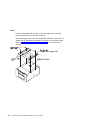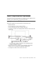
1
IBM 24/48GB 4mm DDS-2 Tape Autoloader Installation and User's Guide (Internal) Note Before using this information and the product it supports, be sure to read the general information under "Product Warranties and Notices" included with your system unit. First Edition (April 1996) The following paragraph does not apply to the United Kingdom or any country where such provisions are inconsistent with local law: THIS PUBLICATION IS PROVIDED “AS IS” WITHOUT WARRANTY OF ANY KIND, EITHER EXPRESS OR IMPLIED, INCLUDING, BUT NOT LIMITED TO, THE IMPLIED WARRANTIES OF MERCHANTABILITY OR FITNESS FOR A PARTICULAR PURPOSE. Some states do not allow disclaimer of express or implied warranties in certain transactions, therefore, this statement may not apply to you. This publication could include technical inaccuracies or typographical errors. Changes are periodically made to the information herein; these changes will be incorporated in new editions of the publication. The manufacturer may make improvements and/or changes in the product(s) and/or the program(s) described in this publication at any time, without notice. It is possible that this publication may contain reference to, or information about, products (machines and programs), programming, or services that are not announced in your country. Such references or information must not be construed to mean that these products, programming, or services will be announced in your country. Any reference to a specific licensed program in this publication is not intended to state or imply that you can use only that licensed program. You can use any functionally equivalent program instead. Requests for technical information about products should be made to your authorized reseller or marketing representative. International Business Machines Corporation 1998. All rights reserved. Note to U.S. Government Users -- Documentation related to restricted rights -- Use, duplication or disclosure is subject to restrictions set forth is GSA ADP Schedule Contract with IBM Corp. Contents Safety Information . . . . . . . . . . . . . . . . . . . . . . . . . . . . . . . . . . . . . v About This Book . ISO 9000 . . . . . . Related Publications . . . . . . . . . . . . . . . . . . . . . . . . . . . . . . . . . . . . . vii vii vii . . . . . . . . . . . . . . . . . . . . . . . . . . . . . . . . . . . . . . . . . . . . . . . . . . . . . . . . . . . . . . . . . . . . . . . . . Chapter 1. Overview . Inventory . . . . . . . . . Product Features . . . . Software Requirements . Handling the Tape Drive Drive Preparation . . . . . . . . . . . . . . . . . . . . . . . . . . . . . . . . . . . . . . . . . . . . . . . . . . . . . . . . . . . . . . . . . . . . . . . . . . . . . . . . . . . . . . . . . . . . . . . . . . . . . . . . . . . . . . . . . . . . . . . . . . . . . . . . . . . . . . . . . . . . . . . . . . . . . . . . . . . . . . . . . . . . . . . . . . . . . . . . . . . . . . . . . . . . . . . . . . . . . . . . . . Chapter 2. Preparing for Installation Installation Requirements . . . . . . . Switch and Jumper Settings . . . . . . . . . . . . . . . . . . . . . . . . . . . . . . . . . . . . . . . . . . . . . . . . . . . . . . . . . . . . . . . . . . . . . . . . . . . . . . . . Chapter 3. Installing the 4MM Tape Autoloader Remove System Unit Covers . . . . . . . . . . . . 4mm Tape Autoloader Installation . . . . . . . . . Chapter 4. Software Installation Verifying Device Driver Installation Diagnostics . . . . . . . . . . . . . . . . . . . . . . . . . . . . . . . . . . . . . . . . . . . . . . . . . . . . . . . . . . . . . . . . . . . . . . . . . . . . . . . . . . . . . . . . . . . . . . . . . . . . . . . . . . . . . . . . . . . . . . . . . . . . . . . . . . . . . . . . . . . . . . . . . . . . Chapter 5. Using the 4mm DDS-2 Tape Autoloader Applying Power to the 4mm DDS-2 Tape Autoloader . Loading a Magazine . . . . . . . . . . . . . . . . . . . . Ejecting a Magazine . . . . . . . . . . . . . . . . . . . . Forcing an Ejection . . . . . . . . . . . . . . . . . . . . . Modes . . . . . . . . . . . . . . . . . . . . . . . . . . . . . Controls and Indicators . . . . . . . . . . . . . . . . . . . Chapter 6. Maintenance Head Cleaning . . . . . . . . . . . . . . . . . . . . . . . . . . . . . . . . . . . . . . . . . . . . . . . . . . . . . . . . . . . . . . . . . . . . . . . . . . . . . . . . . . . . . . . . . . . . . . . . . . . . . . . . . . . . . . . . . . . . . . . . . . . . . . . . . . . . . . . . . . . . . . . . . . . . . . . . . . . . . . . . . . . . . . . . . . . . . . . . Appendix A. Communications Statements . . . . . . . . Federal Communications Commission (FCC) Statement . European Union (EU) Statement . . . . . . . . . . . . . . . International Electrotechnical Commission (IEC) Statement United Kingdom Telecommunications Safety Requirements 1-1 1-2 1-3 1-4 1-4 1-4 2-1 2-1 2-2 3-1 3-1 3-1 4-1 4-1 4-1 5-1 5-1 5-2 5-4 5-5 5-7 5-8 6-1 6-1 . . . . . . . . . . . . . A-1 A-1 A-2 A-2 A-2 Contents iii . . . . . . . . . . . . . . . . . . . . . . . . . . . . . . . . . . . . . . . . . . . . . . . . . . . . Avis de conformité aux normes du ministère des Communications du Canada Canadian Department of Communications Compliance Statement . . . . . . . VCCI Statement . . . . . . . . . . . . . . . . . . . . . . . . . . . . . . . . . . . . Radio Protection for Germany . . . . . . . . . . . . . . . . . . . . . . . . . . . . iv 4mm DDS-2 Tape Autoloader Installation and User's Guide . . . . . . . A-4 A-4 A-4 A-4 Safety Information DANGER An electrical outlet that is not correctly wired could place hazardous voltage on metal parts of the system or the devices that attach to the system. It is the responsibility of the customer to ensure that the outlet is correctly wired and grounded to prevent an electrical shock. Before installing or removing signal cables, ensure that the power cables for the system unit and all attached devices are unplugged. When adding or removing any additional devices to or from the system, ensure that the power cables for those devices are unplugged before the signal cables are connected. If possible, disconnect all power cables from the existing system before you add a device. Use one hand, when possible, to connect or disconnect signal cables to prevent a possible shock from touching two surfaces with different electrical potentials. During an electrical storm, do not connect cables for display stations, printers, telephones, or station protectors for communication lines. Safety Information v vi 4mm DDS-2 Tape Autoloader Installation and User's Guide About This Book This book (when used with your system unit documentation) will help you install and use the 4mm DDS-2 Tape Autoloader. ISO 9000 ISO 9000 registered quality systems were used in the development and manufacturing of this product. Related Publications This book refers to the documentation that came with your computer. About This Book vii viii 4mm DDS-2 Tape Autoloader Installation and User's Guide Chapter 1. Overview The 4mm DDS-2 Tape Autoloader is a digital tape backup-and-restore system that is designed to hold up to six 120m tape cartridges in a removable magazine. The autoloader can back up as much as 8GB of data on a single cartridge in about 2 hours or 48GB of data overnight without operator intervention. The Autoloader implements DDS**-2 (Digital Data Storage-2) format and supports two data-access modes: sequential and random. High-speed file retrieval and tape swapping allow fast access to any file. Note: There are 2 versions of the 4mm DDS-2 Tape Autoloader. This installation and user's guide shows the tape autoloader in the horizontal mounting position. Depending on your system unit type/model the tape autoloader may need to be mounted in its vertical position. Note the only difference between the versions is the front bezel printing and the LCD. ** Trademark of Sony Corporation. Chapter 1. Overview 1-1 Inventory In addition to this manual this package contains: Tape Autoloader Tape magazine - holds up to six digital tape cartridges Note: The tape magazine may be shipped preloaded in the tape autoloader. To remove the tape magazine, press the eject button after installation of the tape autoloader is complete and the system unit has been powered up. An accessory kit containing: – Cleaning Cartridge – Blank Data Cartridge – Blank Test Cartridge 2-Drop Power cable 50 to 68 pin Interposer Mounting hardware - 4 (M3 x 4) metric screws Note: Locate the device mounting plate which was shipped in your system unit media bays. 1-2 4mm DDS-2 Tape Autoloader Installation and User's Guide Product Features The 4mm DDS-2 Tape Autoloader has a cartridge-changer mechanism that: Is compatible with the SCSI-2 Medium Changer command set Has a SCSI-2 interface for the drive and changer Has a standard 5-1/4 inch, full-height form factor Requires no operator maintenance apart from regular head cleaning Is easy to use Takes an average of only 90 seconds to swap a tape cartridge and locate a file The DDS-2 drive (embedded in the 4mm DDS-2 Tape Autoloader) has the following features: Built-in ability to compress and decompress data A sustained streaming transfer rate of 510KB/second with no compression; typically twice this rate using data compression High reliability, with a mean-time-between-failure rate of more than 200,000 hours A large data buffer (1MB) (MB equals approximately 1,000,000 bytes) to maintain the host's transfer rate Automatic error detection and correction Read-after-write error detection and correction Three levels of error correcting code (ECC) Synchronous and asynchronous communication modes Single-ended SCSI configuration Electrically upgradeable firmware through SCSI, or through a Firmware Upgrade tape Compatibility with the SCSI-2 Sequential Access command set No operator maintenance apart from regular head cleaning Compatibility of format with other DDS-2 drives, and backward compatibility with DDS-1 and DDS-DC drives. Chapter 1. Overview 1-3 Software Requirements The 4mm DDS-2 Tape Autoloader requires AIX Version 4.2 or later. The tape drive can be used with the backup, restore, cpio, and tar commands by manually loading and unloading. The complete tape autoloader (tape drive and media changer) can be used for save/restore operations with appropriate applications. Handling the Tape Drive Attention: Static electricity can damage your equipment. Leave the tape drive in its static-protective bag until you are ready to configure or install it in your computer. Drive Preparation Attention: Never remove, install, or transport the 4mm Tape Autoloader with tape cartridges loaded in the magazine. They can become dislodged and jam the mechanism. If the tape autoloader is moved from a colder or warmer environment than which it will be installed, keep the drive in its packing and allow the package to reach room temperature. This will avoid data loss or damage to the tape drive. Allow one hour of acclimation for each 10 degrees C (18 degrees F) difference between the ship/store temperature and the room temperature. Handle the drive carefully and by its external metal chassis. Keep hands away from printed circuit boards, components, and printed circuit (flex) cables. Use a cushioned work surface if possible and do not drop the tape drive onto the work surface. 1-4 4mm DDS-2 Tape Autoloader Installation and User's Guide Recommendations Attention: Tape cartridges that do not carry the proper DDS symbol cannot be written to, and their use will cause the 4mm DDS-2 Tape Autoloader to report an error. Use only 4mm Digital Data Storage (DDS) cartridges. Clean the tape path by using the recommended cleaning cartridge. Follow the instructions on the cartridge. Attention Use of other than recommended cleaning cartridges can damage your tape drive and will void the drive warranty. Back up and then discard any tape cartridge that repeatedly produces error messages. The error information is in the system error log. Do not open the door on the data cartridge that covers the tape. This door protects the magnetic tape material from dirt, dust, and damage. Do not operate in a dusty environment. Do not touch the tape material. Any substance transferred to the tape by touching it could cause loss of data. Types of 4mm Tape Cartridges The 4mm DDS-2 Tape Autoloader is shipped with three 4mm cartridges to help start your tape operations immediately. 4mm Data Cartridge Use this non-labeled cartridge for saving or restoring your programs or data. Additional data cartridges can be ordered through your local sales representative. Cleaning Cartridge Use this cartridge for cleaning the 4mm tape path. For more information, see “Head Cleaning” on page 6-1. Additional cleaning cartridges can be ordered through your local sales representative. Test Cartridge Reserve this cartridge for use by service personnel, or when running diagnostics. Chapter 1. Overview 1-5 Tape Cartridge Compatibility The 4mm DDS-2 Tape Autoloader is compatible with existing 4mm tape subsystems that are designed to operate with Digital Data Storage approved media, which meet the following standards: For DDS – American National Standard (ANSI) standard, X3.203-191, Helical-scan Digital Computer Tape Cartridge, 3.81mm. – European Computer Manufacturers Association (EMCA) standard, EMCA-150, 3.81mm Wide Magnetic Tape Cartridge and DDS format. For DDS2 – European Computer Manufacturers Association (EMCA) standard, EMCA/TC17/93/20, 3.81mm Wide Magnetic Tape Cartridge for Information Interchange Helical Scan Recording, DDS2 format. You cannot change the density setting of the drive because the device reconfigures itself automatically, depending on the media type installed, as follows: Media Type Device Configuration DDS Read-only (60m). DDSllll Read/write in 2.0GB mode only (90m). DDS2 Writes 4.0GB, reads in either density (120m). Non-DDS Not supported. The cartridge will eject. Setting the Write-Protect Tab on 4mm Tape Cartridges The window on the tape cartridge controls write-protection. When the write-protect tab of a tape cartridge is set (window open), information can be read from the tape, but cannot be written to it. When the write-protect tab of a tape cartridge is not set (window closed), information can be both written to and read from the tape. Trying to write to a 4mm data cartridge with the window open causes an error. 1-6 4mm DDS-2 Tape Autoloader Installation and User's Guide Environmental Considerations for 4mm Data Cartridges Information in this section describes operating and storage conditions including temperature, relative humidity, and maximum wet bulb data. Attention: The manufacturer has specified a set of temperature and humidity ranges in which the 4mm data cartridge can operate with ease. Only regular cleaning procedures, as described in “Head Cleaning” on page 6-1 are required when operating the cartridge within this range. The risk of possible data loss is increased if 4mm tape cartridges are operated, stored, or shipped outside the temperature or humidity ranges shown in the following table. Before using a cartridge, always let it adjust (acclimate) to the operating environment. Do this by placing the cartridge with its container in the operating environment for as long as it has been away from this environment or for 24 hours, whichever is less. Acclimation is necessary for any data cartridge that has been exposed to a different humidity environment or a temperature change of 11°C or 20°F or more. Temperature Relative Humidity (non-condensing) Maximum Wet Bulb Operating Ranges Storage Shipping 16°C to 32°C (60°F to 90°F) 20 to 80% 5°C to 32°C (40°F to 90°F) 20 to 80% -40°C to 52°C (-40°F to 125°F) 5 to 80% 26°C (79°F) 26°C (79°F) 26°C (79°F) Chapter 1. Overview 1-7 Operating in Harsh Environments The 4mm DDS-2 Tape Autoloader is ideally suited to streaming operations, as opposed to tape movement operations involving multiple stop/starts and random searches. Streaming movement is beneficial and should be used whenever possible. Any tape that has been used outside the ranges specified in the previous table for an extended period of time (50 passes in 40 hours of nonstop operation) should not be used as an archival tape. Exposure to the environment will deteriorate the magnetic and physical strength of the tape. Do not store important data on a tape that has been used outside the specified ranges; transfer the data to a new tape for reliable archiving. 4mm Data Cartridge Erasure Most bulk eraser devices do not have the capability to erase 4mm data cartridges. To properly erase an 4mm data cartridge with a bulk eraser device, the erasure rating must be at least 2000 oersted. The 4mm DDS-2 Tape Autoloader erases residual data before writing new data on the data tape. Tape Cartridge Data Capacity The 4mm tape cartridge capacity is defined as the amount of data that can be stored on the cartridge. The following variables affect the amount of data that can be stored on a tape cartridge: Size of the data file Number of file marks per file Compatibility mode (2GB or 4GB) Media rewrites Nature of the data being stored. Text files are usually stored with greater compression than binary files. Cartridge format/length 1-8 4mm DDS-2 Tape Autoloader Installation and User's Guide Chapter 2. Preparing for Installation The installation process consists of: Taking an inventory of all pieces necessary for installation Switch and Jumper Settings Planning your SCSI device layout Setting the SCSI address of your SCSI tape autoloader Installing the SCSI tape autoloader Software Installation Installation Requirements To install the 4mm DDS-2 Tape Autoloader you need: The 4mm tape autoloader and mounting hardware The documentation that came with your system unit The documentation that came with your 4mm tape autoloader A 16-bit to 8-bit (50 to 68 pin) SCSI interposer if you are connecting the tape drive to a 16-bit SCSI cable. A flat-blade screwdriver. Chapter 2. Preparing for Installation 2-1 Switch and Jumper Settings Option Switches The option switches are located on the back of the Autoloader. These switches must be in the on position. The 4mm DDS-2 Tape Autoloader reads the option switches at power-up time and during self-test. 2-2 4mm DDS-2 Tape Autoloader Installation and User's Guide Configuration Switches The configuration switches are located on the bottom of the Autoloader. Switches 3 and 4 must be off, all of the other switches must be on. The 4mm DDS-2 Tape Autoloader reads the configuration switches at power-up time and during self-test. Chapter 2. Preparing for Installation 2-3 Planning your SCSI Device Layout SCSI devices are attached to a SCSI adapter in a chain. Devices in the chain can be internal (inside your system unit) or external (connected outside your system unit). If you are connecting more than one SCSI device, it is important that you plan the layout of your SCSI chain. Note: At each end of the SCSI chain, a terminator is required. Planning SCSI Addresses Make sure no two SCSI devices have the same address, and that no device uses the SCSI address 7, which is used by the SCSI adapter. If the system and adapter supports the Wide (16 data bit, 68 conductor cable) SCSI interface, you may see addresses in the range of 0 through 15. Note: For addresses in the range of 0 through 7, priority is assigned in descending address order. Refer to Table 2-1 for the priority associated with each SCSI address. Table 2-1. Data Access Priorities for SCSI Addresses Highest Priority | | | | | | | | | | | | | v Lowest Priority 2-4 7 6 5 4 3 2 1 0 15 14 13 12 11 10 9 8 Adapter 4mm DDS-2 Tape Autoloader Installation and User's Guide Setting the SCSI Address Note: Prior to installing the SCSI media device into the media bay, the address of the device must be set to any of the available SCSI addresses. If the system is currently not running, find the documentation listing the SCSI addresses already assigned. 1. Determine what SCSI addresses are in use and what addresses are available by entering the following command: lsdev -Cs scsi This command returns the following information: Column Column Column Column 1: 2: 3: 4: device name (for example, scsið) device status (for example, Available) SCSI location code (the format is: nn-nn-nn-a,l) device type (for example, CD-ROM drive, 2.3GB tape drive, etc.) The a in the nn-nn-nn-a,l string returned in Column 3 is the SCSI address of the associated device. The l is the logical unit number (LUN). Record the names and SCSI addresses of your installed SCSI devices in Table 2-1 on page 2-4. Then choose the highest-priority unused SCSI address for your new tape autoloader. Chapter 2. Preparing for Installation 2-5 Setting the SCSI ID The SCSI ID is set by using jumpers on the pins beside the SCSI connector at the rear of the drive. The jumper connects two adjacent pins together to represent a position. Notes: These jumpers are unique in that the address setting pins are aligned horizontally (side by side). When not being used, the jumpers can be stored on the device by turning them sideways thus engaging only one of the pins. Term Power is never used; leave the first jumper in the "stored" position. The 4mm DDS-2 Tape Autoloader is shipped with the SCSI ID set to 0. The 4mm DDS-2 Tape Autoloader reads the SCSI ID at power-up time during self-test. The three bits in the ID give a range of 0 through 7 as follows: 2-6 4mm DDS-2 Tape Autoloader Installation and User's Guide Chapter 3. Installing the 4MM Tape Autoloader Remove System Unit Covers Refer to the documentation that came with your system unit for directions on shutting down your system and removing the system unit covers. 4mm Tape Autoloader Installation 1. Refer to the documentation provided with your system unit to install an internal device. 2. Locate and remove the two hardware mounting plates (shipped with the system unit) from the media bay. Store one of the mounting plates in a safe place for future use, the other mounting plate will be used to mount the 4mm DDS-2 Tape Autoloader. 3. Locate the four (M3 x 4mm) metric screws (shipped with the tape autoloader). 4. Using the four metric screws connect the mounting plate to the bottom of the tape autoloader. (refer to the following illustration) Chapter 3. Installing the 4MM Tape Autoloader 3-1 Notes: Point mounting plate tabs (located on the front edge of the mounting plate) toward the front of the tape autoloader. The mounting plate will cover the configuration switches, if you have not already set the configuration switches do so before you mount the plate. Refer to “Configuration Switches” on page 2-3 for the correct switch settings. 3-2 4mm DDS-2 Tape Autoloader Installation and User's Guide 5. Connect the 2-drop power cable to the connectors located on the rear of the 4mm tape autoloader as shown in the following illustration. Note: There are 2 female connectors and one male connector which make up the 2-drop power cable. The 2 female connectors will be connected to the rear of the tape autoloader, the male connector will be connected to the power distribution cable, located in the system unit. 6. (In the system unit) Locate the SCSI Cable connector which will be used to attach the tape autoloader; install the 50 to 68 pin Interposer to the SCSI cable. (This will allow for a better alignment of the connector and pins, and avoid potential pin-bending.) 7. To install the 4mm Tape Autoloader, refer to the Installing Internal Drives section of your system unit documentation. After completing the installation return to Chapter 4, “Software Installation” on page 4-1 in this manual to verify the device and device driver installation. Chapter 3. Installing the 4MM Tape Autoloader 3-3 3-4 4mm DDS-2 Tape Autoloader Installation and User's Guide Chapter 4. Software Installation When you power-on your system it will automatically configure the addition of the 4mm tape autoloader. Verifying Device Driver Installation To verify that your newly installed 4mm (DDS-2) Tape Autoloader is available for use, follow the steps below: 1. At the prompt, type: lsdev -Cs scsi | grep rmt 2. A list of SCSI tape drives displays. Verify that a "SCSI 4mm Tape Drive" exists at the SCSI ID used, and is in the Available state. To confirm, note the resource name (rmtx); at the prompt type: lscfg -l rmtx -v The following should appear on the screen. Manufacturer. . . . . . . . . . . . . . .HP Machine Type and Model. . . . . .C1553A Diagnostics The tape diagnostics in AIX 4.2 or later are designed to run with the tape drive located in the tape autoloader. The tape changer located in the tape autoloader does its own self-test at Power-On and when a tape magazine is inserted. A blank test cartridge is supplied with the accessory kit. Use this test cartridge when running the diagnostics. Chapter 4. Software Installation 4-1 4-2 4mm DDS-2 Tape Autoloader Installation and User's Guide Chapter 5. Using the 4mm DDS-2 Tape Autoloader The operator will need to load cartridges into a magazine, load the magazine into the Autoloader, use the operator panel, and clean the tape heads. Applying Power to the 4mm DDS-2 Tape Autoloader When power is applied to the tape autoloader the following takes place: All three LED's light The LCD displays the currently configured SCSI ID The LED's start flashing and the LCD displays SELFTEST If a magazine is loaded, the LCD displays MAG CHECK as it verifies which slots contain media. – As the individual cartridges are identified, their corresponding location numbers are displayed on the LCD. When all testing has been completed, the tape autoloader displays MAG LOADED on the LCD and lights the MAGAZINE PRESENT LED. If no magazine is loaded, continue with the next section. Chapter 5. Using the 4mm DDS-2 Tape Autoloader 5-1 Loading a Magazine Attention: Cartridge and magazine labels must be firmly affixed to the recessed label areas; otherwise, the mechanism will jam. Labels must not be peeling off. Labels must not go over the edge of the label area. Labels must not be folded over the edge of cartridges. Labels must not be stuck on top of another label. 5-2 4mm DDS-2 Tape Autoloader Installation and User's Guide Attention: Only cartridges labeled with the DDSllll or DDS2 logo should be used in the Autoloader. Refer to “Recommendations” on page 1-5 to reference the correct DDS2 and DDSllll logos. It is recommended that you store cartridges in their magazines, so that cartridges belonging to a multi-volume backup are kept together and in the correct order. 1. Align the arrow on the cartridge with the arrow on the magazine and insert the cartridge in the magazine. Insert up to 6 cartridges into any of the magazine slots. Chapter 5. Using the 4mm DDS-2 Tape Autoloader 5-3 2. Insert the cartridge magazine into the slot in the front of the Autoloader with the large arrow on the magazine facing up and pointing towards the Autoloader. Apply steady pressure until the mechanism takes the magazine and pulls it into the Autoloader. Ejecting a Magazine To eject the magazine, press the Eject button. When you do this: 1. If a tape is loaded, the tape will rewind to the beginning of the partition (BOP). 2. If the tape is write-enabled, the updated copy of the Tape log is written back to tape. 3. The tape rewinds to BOM and is unthreaded. 4. The changer replaces the cartridge in the magazine. 5. The magazine is ejected. 5-4 4mm DDS-2 Tape Autoloader Installation and User's Guide Forcing an Ejection Attention: Force an ejection only as a last resort to recover a cartridge. Never use it as a quick way of ejecting the cartridge. You can lose data if you force an eject. The tape also might end up invalidly formatted, because EOD might not have been written. If you press the Eject button when the drive is busy, the drive first completes the current task. Then it responds to the ejection request. This ensures that the task is terminated in a controlled manner and that no data is lost. There might be occasions when you need to unload a cartridge urgently, even at the risk of losing data. To do this, you must force an ejection: 1. Press and hold the Eject button for at least 5 seconds. The LCD will display "Force Eject." 2. The Autoloader waits 35 seconds to give the normal ejection process a chance to occur. 3. When this period elapses, any tape in the drive is immediately unthreaded, and the cartridge is ejected, regardless of what operation the drive was performing. The cartridge then is returned to its slot in the magazine, and the drive is reset as though power had been cycled. Because forced ejection might interrupt an operation, it is possible that the drive will not write EOD before the cartridge is ejected. This will cause a loss of data and an invalid formatting of the cartridge. The data on such a cartridge should be readable up to the point where the format violation occurred. 4. If no cartridge is loaded in the drive, the Autoloader waits 35 seconds, ejects the magazine, and then resets as though power had been cycled. Removal If for any reason the Tape Autoloader needs to be removed from the system unit, be sure to keep the 2-drop power cable and the 50 to 68 pin interposer with the tape autoloader. Chapter 5. Using the 4mm DDS-2 Tape Autoloader 5-5 Loading and Unloading Cartridges Refer to “Controls and Indicators” on page 5-8 for a detailed description of the 4mm tape autoloader controls and indicators. When a Magazine containing cartridges has been inserted into the tape autoloader, some applications can begin because they use the Move Medium commands which can select and load cartridges. Many applications, including the AIX commands mksysb, tar, backup, cpio, will operate only with a tape drive which has the media loaded (is Ready). The tape drive must be loaded with an appropriate cartridge to boot from the tape drive, or to run diagnostics on the tape drive. The tape drive can be loaded manually using the controls on the front of the tape autoloader. To load a tape cartridge into the tape autoloader, use the Select button on the front panel. After selecting one of the tape cartridges from the Magazine, press the Load Tape button. This will cause the selected tape cartridge to be moved from the magazine to the tape drive. The tape drive will then start a load cycle automatically. Pressing the Load Tape button when the Select digit is "0" will cause the loading of the first available tape cartridge into the magazine. The tape drive may encounter difficulties in loading the tape cartridge. Observe the loading process to ensure it completes successfully. Note: AIX and most other using applications typically communicate with Ready devices and may be unaware if the Load Tape process has failed. If the Load Tape process fails, the tape autoloader will retry the cycle several times. The operator will be signaled of the load failure by a flashing (Yellow) Operator Attention Required LED and messages on the LCD. If an Error Message is displayed (e.g. Error 112) alternating with the instruction, " PressEject", the operator should press the Eject button which will cause the magazine to be ejected with the unloadable cartridge. If a second cartridge also fails to load, the drive may be defective. However, if a substitute cartridge loads successfully, the original cartridge may be defective. When a cartridge has been loaded, the LCD will display the READY message, and the application, diagnostic, or command can be initiated or continued. On initial manual loading, the tape autoloader is in a Sequential Mode. In this mode, an Unload command issued to the drive will cause the cartridge to be placed back in its assigned slot in the magazine and the next available cartridge to be loaded. This process ends when the cartridge in the highest numbered occupied slot of the magazine has been processed. Most AIX commands such as mksysb, tar, and backup do not issue Unload commands at the end of the command or at the end of the tape. When not 5-6 4mm DDS-2 Tape Autoloader Installation and User's Guide controlled by the command or application, the operator should cause the unload by pressing the Eject button (making sure that the application or command is finished with the cartridge). The magazine will eject when operating in this single cartridge mode. Re-insert the Magazine, and select the next or appropriate cartridge to continue or to initiate a new command or application. Don't reuse the cartridge just unloaded if it contains important data (such as your 'backup' data). Modes The Autoloader can operate in two modes, sequential or random. Sequential In sequential mode, the Autoloader does not depend on host implementation of changer commands. You can select which cartridge to initially load by using the Select and Load buttons on the front panel. Refer to “Controls and Indicators” on page 5-8 for button and indicator location. When a cartridge is ejected from the drive following a host UNLOAD command, the Autoloader will automatically load the next available cartridge from the magazine into the drive. Random In random mode, the host views the Autoloader as two devices: A changer mechanism to which SCSI Medium Changer commands can be sent. A tape drive to which SCSI Sequential Access commands can be sent. The controlling host computer therefore has full random access to any cartridge. Most PC backup/restore applications automatically load, unload, and clean the Autoloader using the random access mode. Refer to your backup/restore software instructions for additional details. Chapter 5. Using the 4mm DDS-2 Tape Autoloader 5-7 Controls and Indicators Select Button The Select button allows you to select a cartridge from the magazine in the unit. The number of the cartridge selected is displayed on the left side of the LCD. If you press the Select button repeatedly, the display cycles through the cartridges available in the magazine. Eject Button The Eject button starts the unload process. The drive unloads any currently loaded cartridge, and the changer mechanism returns it to the magazine. The magazine is then ejected. Note: Refer to “Forcing an Ejection” on page 5-5. Load Tape Button The Load Tape button is used to load the selected cartridge from the magazine into the drive. The drive then goes into sequential mode, automatically loading the next highest numbered cartridge. Note: When in Random Mode, the select and load buttons are disabled. Their function is controlled by host software. Magazine Present (LED) Steady Green: A magazine is in the Autoloader. Flashing Green: A magazine is being loaded, checked, or ejected. 5-8 4mm DDS-2 Tape Autoloader Installation and User's Guide Tape Activity (LED) This light indicates what is happening to the cartridge in the drive: Steady Green: A cartridge is present in the drive Rapidly Flashing (twice per second) Green: Data is being read or written Slowly Flashing (once per second) Green: A cartridge is being loaded or unloaded. Operator Attention Required (LED) This light indicates that the operator needs to take some action: Steady Amber: A serious hardware error has occurred. If a power reset does not eliminate the problem, the tape autoloader will require service. Flashing Amber: A user-recoverable error has occurred: – The front-panel door is open. – A cartridge is in the drive, but no magazine is present. – The tape heads need cleaning. – The tape is nearing the end of its useful life. – A firmware upgrade is occurring. When the Operator Attention Required LED is on or flashing, an error message might be displayed in the Status LCD. These error messages are explained under “Error Messages” on page 5-13. Chapter 5. Using the 4mm DDS-2 Tape Autoloader 5-9 Status Liquid Crystal Display The Status LCD displays a range of autoloader status information in each of its five display regions: .1/ A 10-character display provides operating status information and potential error conditions (see "LCD Message Categories" below). .2/ A 7-segment display shows the number of the cartridge currently loaded in the drive, or the cartridge selected when the Select button is pressed repeatedly. .3/ "DC" indicates that data compression is being used for writing; "WP" indicates a Write-Protected cartridge. .4/ Six numbered boxes individually light to show which magazine slots contain a cartridge. .5/ An "odometer" line shows how much tape has been used in the active partition of the current cartridge. The more lines that are shown, the more tape that has been used. LCD Message Categories: The LCD can show three types of messages: Autoloader status messages Information messages Error messages 5-10 4mm DDS-2 Tape Autoloader Installation and User's Guide Autoloader Status Messages: The following is a list of possible status messages and their brief descriptions: Cleaning A cleaning cartridge is in the drive. Erase The drive is erasing data from the tape. Format The drive is creating a 1- or 2-partition tape, or changing the size of the partitions on an existing 2-partition tape. FW Check The data to upgrade the firmware is being checked for compatibility. FW Program The drive is being upgraded with the new firmware. FW Upgrade Data to upgrade the firmware is being read from a tape or through the SCSI bus. Insert Mag There is no magazine in the Autoloader. Loading Either a cartridge is being moved from the magazine and inserted into the drive, or the drive is loading a semi-loaded cartridge. Locate The drive is moving the tape to a point specified by the host. Mag Check The Autoloader is examining the magazine to find which slots are occupied. Mag Eject The Autoloader is ejecting the magazine. Mag Loaded A magazine is loaded, and the magazine check has been completed. New FW!!! The firmware has been successfully upgraded. Partition The drive is switching to the other partition on a 2-partition tape. Read The drive is reading data from tape. Ready xxm A cartridge is loaded in the drive, and the drive is ready to respond to commands that cause tape motion. "xxm" is the length of the currently loaded tape, so "Ready 90m" will be displayed when a 90-m tape is loaded. If a write-protected tape is loaded, "Ready xxm" alternates with "Read Only." Rewind The drive is rewinding the tape to the beginning of the partition. Search >> The drive is searching for a record, file mark, set mark, or EOD in the direction towards the end of the tape (in other words, it is responding to a SCSI SPACE command with a positive Count field). Search << The drive is searching for a record, file mark, set mark, or EOD in the direction towards the beginning of the tape (in other words, it is responding to a SCSI SPACE command with a negative Count field). Self Test The Autoloader is performing its power-on self-test. Chapter 5. Using the 4mm DDS-2 Tape Autoloader 5-11 SemiLoaded A cartridge is in the drive, but not loaded. Unloading Either the drive is unloading a cartridge, or a semiloaded cartridge is being ejected and moved back to its slot in the magazine. Write x.y The drive is writing data to tape. "x.y":1 is the cumulative compression ratio since the power was turned on, or since the compression ratio was last cleared. For example, "Write 2.1" means a compression ratio of 2.1:1. The compression ratio will be displayed after a 1MB of data has been written since the power was turned on. Information Messages: The following information messages can be displayed: Config: xxy "xx" is the hexadecimal value of the Configuration switches situated on the underside of the Autoloader; "y" is the hexadecimal value of the switches on the rear of the Autoloader. Eject Mag The Eject button has been pressed. Force Eject A forced ejection is in progress, (refer to “Forcing an Ejection” on page 5-5). It remains until the magazine is ejected. Load Tape The Load Tape button has been pressed. SCSI ID: x "x" is the Autoloader's SCSI address. Select Tape Displayed when the Select button is pressed, and for a short time afterwards. Stray Tape: Insert Empty Mag A cartridge is in the drive mechanism, although no magazine is inserted. Insert an empty magazine to retrieve the cartridge. 5-12 4mm DDS-2 Tape Autoloader Installation and User's Guide Error Messages The following tables list some of the error messages you might encounter. Also provided are descriptions of the messages and suggested courses of action. These messages appear on the LCD. Messages longer than 10 characters scroll across the LCD. Message Meaning Action At BOD A SPACE command encountered BOD unexpectedly. Retry the backup/restore operation. At EOD A READ or SPACE command encountered the EOD area unexpectedly. Retry the backup/restore operation. Tape has DC Data A READ command has encountered compressed data on the tape, and the drive is not currently set up to decompress data. Make sure configuration switches are set correctly. SCSI Error A SCSI command error has been detected. Check the SCSI bus connection and then retry the backup/restore operation. Partition1 too large A command to format the tape has failed because the requested size for partition 1 is too large. Retry the backup operation using 120M tape. Tape Full A READ, SPACE, WRITE or WRITE FILEMARKS command encountered EOP unexpectedly. Retry backup operation with a longer or new tape. Bad Media A READ or SPACE command has failed because the tape is not in DDS format. Replace tape with DDS-certified tape, then retry operation. Cannot Write Non-MRS Tape A WRITE, WRITE FILEMARK or ERASE command has been attempted on a non-MRS tape. Replace tape with a MRS Data Grade tape, then retry operation. Clean Me A high error rate has been detected while reading or writing. Insert a cleaning cartridge to clean the tape heads, then retry operation. Close Door The front panel door is open. Any autoloader motion will be delayed until the door is closed. Close the door. Eject Fail An EJECT command has failed. Press the Eject button for 5 seconds (Forced Eject) to recover the cartridge and magazine. Try turning the power off and then back on. Check that labels are correctly affixed to the magazine and cartridge. Chapter 5. Using the 4mm DDS-2 Tape Autoloader 5-13 Message Meaning Action Error x The mechanism has jammed. Press the Eject button for 5 seconds (Forced Eject) to recover the cartridge and magazine. Try turning the power off and then back on. Check that labels are correctly affixed to the magazine and cartridge. If the problem persists, call for service. Force Eject A forced ejection is in progress. Wait for the 35-second pause to elapse. FW DataErr The Autoloader has failed to upgrade the drive firmware because the new firmware is unreliable. Obtain a good copy of the firmware upgrade. FW Read Fail A firmware upgrade failed because of an error in reading data from the tape. Clean the tape heads, then retry operation. FW Tape Write Protected A firmware upgrade failed because the tape is write-protected. Change the write-protect switch on the tape and retry operation. FW Write Fail A firmware upgrade failed because of an error in writing a modified upgrade count to the tape. Clean the tape heads. Try again Illegal FW The Autoloader has failed to upgrade the drive firmware because the new firmware is incompatible with the hardware. Obtain a correct version of the firmware upgrade, then retry operation. Illegal HW The Autoloader has failed to upgrade the drive firmware because the new firmware is for incompatible hardware. Obtain a correct version of the firmware upgrade, then retry operation. Load Fail A LOAD command has failed, or a LOAD PARTITIONS or CHANGE PARTITIONS command has failed to read the System area of the tape. Retry using a new cartridge, or eject the magazine. No EODmark A READ command has encountered blank tape; that is, no DDS-format EOD pattern has been recognized. Retry operation with another tape. Read Fail A read has failed. Clean the tape heads, then retry operation. Try again. The cartridge in the drive is faulty, possibly because the tape has snapped, or the cartridge has an invalid pattern of identification holes. Retry operation with a new cartridge. Tape Position Lost A WRITE, READ, SPACE or REWIND command has failed. The tape is on the far side of the bad data. Clean the tape heads, then retry backup/restore operation. Tape Stuck The cartridge is stuck in the drive. Try forcing an ejection. 5-14 4mm DDS-2 Tape Autoloader Installation and User's Guide Message Meaning Action UpgradeErr The Autoloader has failed to download an upgrade of the firmware via SCSI. Check the SCSI bus connection, then retry the operation. Worn Media A high error rate was detected while writing. The tape probably is nearing the end of its useful life. Clean the tape heads and/or replace the cartridge with a new one. Then retry the operation. Write Fail A WRITE, WRITE FILEMARK, or ERASE command has failed. Clean the tape heads and/or use a new cartridge. Then retry the backup operation. Write Protected Tape A WRITE, WRITE FILEMARK or ERASE command was attempted on a write-protected tape. Change the write-protect switch on the tape and retry the operation. Drive Comms Error The drive is not communicating with the changer mechanism. Call for service. FRU 1 Dead The controller board for the drive has failed its self-test. Call for service. FRU 2 Dead The drive mechanism has failed its self-test. Call for service. Chapter 5. Using the 4mm DDS-2 Tape Autoloader 5-15 5-16 4mm DDS-2 Tape Autoloader Installation and User's Guide Chapter 6. Maintenance Head Cleaning The tape heads should be cleaned regularly, as indicated in the following table. Tape heads also should be cleaned if the "Clean Me" message is displayed on the LCD and the Operator Attention Required LED is flashing amber. Number of DDS cartridge passes each day Cleaning Interval 1 Weekly 2 to 3 Twice a week 4 or more Daily Clean the heads using a cleaning cartridge as follows. Sequential Mode 1. Place the cleaning cartridge into one of the magazine slots (for example, slot 1) and insert the magazine into the Autoloader. 2. Use the Select button to select the slot in which you placed the cleaning cartridge. 3. Press the Load Tape button to load the cleaning cartridge into the drive. The Autoloader then automatically performs a cleaning cycle. 4. Press the eject button to unload the magazine and remove the cleaning cartridge. 5. Record the date on the label of the cleaning cartridge. After 25 uses, discard the cartridge. Random Mode 1. Some backup software will perform the cleaning operation automatically. Using this process, the cleaning cartridge could be in any one of the six magazine slots. The Autoloader will recognize that the cartridge is a cleaning cartridge once it is loaded into the drive. 2. The drive will then automatically carry out a cleaning cycle. 3. The drive automatically ejects the cartridge when the cleaning cycle is complete. The changer returns the cartridge to its magazine slot without any additional user involvement. Refer to your backup/restore software instructions for additional details. Chapter 6. Maintenance 6-1 6-2 4mm DDS-2 Tape Autoloader Installation and User's Guide Appendix A. Communications Statements The following statement applies to this product. The statement for other products intended for use with this product appears in their accompanying documentation. Federal Communications Commission (FCC) Statement Note: The &typemod. been tested and found to comply with the limits for a Class B digital device, pursuant to Part 15 of the FCC Rules. These limits are designed to provide reasonable protection against harmful interference in a residential installation. This equipment generates, uses, and can radiate radio frequency energy and, if not installed and used in accordance with the instructions, may cause harmful interference to radio communications. However, there is no guarantee that interference will not occur in a particular installation. If this equipment does cause harmful interference to radio or television reception, which can be determined by turning the equipment off and on, the user is encouraged to try to correct the interference by one or more of the following measures: Reorient or relocate the receiving antenna. Increase the separation between the equipment and receiver. Connect the equipment into an outlet on a circuit different from that to which the receiver is connected. Consult an authorized dealer or service representative for help. Properly shielded and grounded cables and connectors must be used in order to meet FCC emission limits. Proper cables and connectors are available from authorized dealers. Neither the provider nor the manufacturer are responsible for any radio or television interference caused by using other than recommended cables and connectors or by unauthorized changes or modifications to this equipment. Unauthorized changes or modifications could void the user's authority to operate the equipment. This device complies with Part 15 of the FCC Rules. Operation is subject to the following two conditions: (1) this device may not cause harmful interference, and (2) this device must accept any interference received, including interference that may cause undesired operation. Appendix A. Communications Statements A-1 Responsible Party: International Business Machines Corporation New Orchard Road Armonk, New York 10504 Telephone: (919) 543-2193 Tested to Comply With FCC Standards FOR HOME OR OFFICE USE European Union (EU) Statement This product is in conformity with the protection requirements of EU Council Directive 89/336/EEC on the approximation of the laws of the Member States relating to electromagnetic compatibility. The manufacturer cannot accept responsibility for any failure to satisfy the protection requirements resulting from a non-recommended modification of the product, including the fitting of option cards supplied by third parties. Consult with your dealer or sales representative for details on your specific hardware. This product has been tested and found to comply with the limits for Class B Information Technology Equipment according to CISPR 22 / European Standard EN 55022. The limits for Class B equipment were derived for typical residential environments to provide reasonable protection against interference with licensed communication devices. International Electrotechnical Commission (IEC) Statement This product has been designed and built to comply with IEC Standard 950. United Kingdom Telecommunications Safety Requirements This equipment is manufactured to the International Safety Standard EN60950 and as such is approved in the UK under the General Approval Number NS/G/1234/J/100003 for indirect connection to the public telecommunication network. The network adapter interfaces housed within this equipment are approved separately, each one having its own independent approval number. These interface adapters, supplied by the manufacturer, do not use or contain excessive voltages. An excessive voltage is one which exceeds 70.7 V peak ac or 120 V dc. They interface with this equipment using Safe Extra Low Voltages only. In order to A-2 4mm DDS-2 Tape Autoloader Installation and User's Guide maintain the separate (independent) approval of the manufacturer's adapters, it is essential that other optional cards, not supplied by the manufacturer, do not use main voltages or any other excessive voltages. Seek advice from a competent engineer before installing other adapters not supplied by the manufacturer. Appendix A. Communications Statements A-3 Avis de conformité aux normes du ministère des Communications du Canada Cet appareil numérique de la classe B est conform à la norme NMB-003 du Canada. Canadian Department of Communications Compliance Statement This Class B digital apparatus complies with Canadian ICES-003. VCCI Statement The following is a summary of the VCCI Japanese statement in the box above. This product is a Class B Information Technology Equipment and conforms to the standards set by the Voluntary Control Council for Interference by Information Technology Equipment (VCCI). This product is aimed to be used in a domestic environment. When used near a radio or TV receiver, it may become the cause of radio interference. Read the instructions for correct handling. Radio Protection for Germany Dieses Gerät ist berechtigt in Übereinstimmung mit dem deutschen EMVG vom 9.Nov.92 das EG–Konformitätszeichen zu führen. Der Aussteller der Konformitätserklärung ist die IBM Germany. Dieses Gerät erfüllt die Bedingungen der EN 55022 Klasse B. A-4 4mm DDS-2 Tape Autoloader Installation and User's Guide IBM Part Number: 73H1727 Printed in the United States of America on recycled paper containing 10% recovered post-consumer fiber. 73H1727