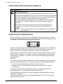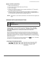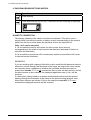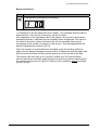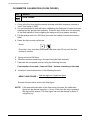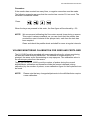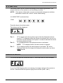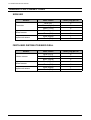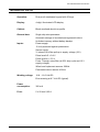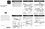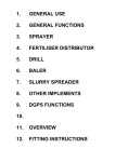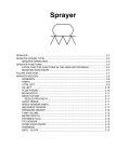
1
OPERATORS MANUAL
FOR THE
LH 1200S SPRAYER MONITOR
LH no. 021-202-UK Version 2.00
LH Technologies Denmark ApS
Mølhavevej 2
9440 Aabybro
Denmark
Tel. +45 9696 2500
Fax. +45 9696 2501
Internet: http://www.lh-agro.com/
LH 1200S OPERATORS MANUAL
2
LH AGRO
LH 1200S OPERATORS MANUAL
Contents
INTRODUCTION .................................................................................................................4
GENERAL USE ...................................................................................................................5
FERTILISER DISTRIBUTOR ..................................................................................5
SEED DRILL ...........................................................................................................6
SYSTEM DESCRIPTION.....................................................................................................7
918-123 LH 1200S FITTING KIT WITHOUT SWITCHES .......................................7
916-123 LH 1200S FITTING KIT WITH SWITCHES...............................................8
THE MONITOR ...........................................................................................................9
PLUG CONNECTIONS ...............................................................................................9
PRIMARY FUNCTIONS.....................................................................................................10
WORK TIME..............................................................................................................10
FORWARD SPEED...................................................................................................10
AREA COUNTERS ...................................................................................................11
APPLICATION RATE FOR SPRAY CHEMICALS.....................................................12
BOOM SECTION COMPENSATION ........................................................................12
SPRAY CHEMICAL CONSUMPTION PER MINUTE................................................13
SPRAY CHEMICAL CONSUMPTION.......................................................................13
SECONDARY FUNCTIONS, FERTILISER DISTRIBUTOR ..............................................14
RPM FOR DISC SPREADERS .................................................................................14
FERTILISER DISTRIBUTOR WITH FEED ROLLER (PNEUMATIC) ........................14
SECONDARY FUNCTIONS, SEED DRILL .......................................................................15
SOW AXLE RPM.......................................................................................................15
SEED RATE MONITORING......................................................................................15
SECONDARY FUNCTIONS; SLURRY SPREADER .........................................................16
APPLICATION RATE MONITORING........................................................................16
SECONDARY FUNCTIONS, BALER.................................................................................17
UNIT COUNTER .......................................................................................................17
SECONDARY FUNCTIONS, DISTANCE MEASURING....................................................17
ENCODING .......................................................................................................................18
FORWARD SPEED CALIBRATION (WHEEL CIRCUMFERENCE) .........................18
AUTOMATIC SPEED SENSOR CALIBRATION ...................................................18
MANUAL SPEED CALIBRATION .........................................................................19
WORKING WIDTH AND BOOM SECTIONS ............................................................19
1. ENCODING THE WORKING WIDTH ...............................................................19
2. ENCODING BOOM SECTIONS WIDTHS.........................................................20
QUANTITY CORRECTION...................................................................................20
FLOWMETER CALIBRATION (FLOW FIGURE) ......................................................22
VOLUME MONITORING CALIBRATION FOR SEED AND FERTILISER.................23
SYSTEM TEST..................................................................................................................25
ERROR WARNING............................................................................................................25
TRAILER PLUG CONNECTIONS .....................................................................................26
SPRAYER .................................................................................................................26
FERTILISER DISTRIBUTOR/SEED DRILL...............................................................26
TECHNICAL DATA ............................................................................................................27
LH AGRO
3
LH 1200S OPERATORS MANUAL
INTRODUCTION
Congratulations with your new LH 1200S sprayer monitor with boom
compensating features.
During development of this monitor we have made a point of producing a durable
product that is primarily developed to monitor chemical application. The monitor,
however, includes a number of other functions, which enable it to be used in
connection with almost any other implement.
If the monitor is used in accordance with the guidelines in this manual, the LH
1200S will be a true and reliable assistant for you for many years.
We have endeavoured to deliver a fault free product. To ensure optimal use of the
equipment we ask that great attention be paid when reading the manual. We are
more than happy to help should any queries arise, both when the product is used
for the first time and at any later date. Regarding responsibility for use of the
product we refer to our sales and delivery terms especially paragraph 7, which
follows:
7.
Product usage.
7.1
Any use of the product is at the sole risk of the buyer. The buyer is
therefore not entitled to any form for compensation caused by, for
example, any of the following:
Disturbance to/from any electronic services or products that do
not confirm to the standards for CE marking,
Missing or poor signal coverage or a succession hereof from
external transmitters/receivers, used by the buyer,
Functional faults, which apply to or from a PC-program or PCequipment, not delivered by the seller,
Faults that may arise from the buyers negligence to react to
warnings and fault messages from the product, or which can be
traced to negligence and/or absent constant control of the work
carried out in comparison to the planned job.
7.2
4
When implementing any new equipment the buyer must take great care and
pay attention. Any doubts as to correct operation/use should result in
contacting the sellers service department.
LH AGRO
LH 1200S OPERATORS MANUAL
GENERAL USE
The LH 1200S is especially designed for use on a crop sprayer. The following
functions can be selected directly from the keypad:
1. Work time
2. Forward speed
3. Area counters (trip- and total)
4. Chemical application rate
5. Chemical consumption per minute
6. Chemical consumption (litre counter)
The monitor can also be used in connection with other implements by encoding
some special values (codes).
The secondary functions are as follows:
Distance in metres
Shaft speed (RPM)
Fertiliser application rate
Sow seed application rate
Fertiliser consumption (Kg counter)
Sow seed consumption ( Kg counter)
Unit counter
These functions can placed into the following implement related sets:
FERTILISER DISTRIBUTOR
A:
B:
Work time
Forward speed
Area trip counter
Area total counter
Shaft speed (RPM)
Work time
Forward speed
Area trip counter
Area total counter
Fertiliser application rate
Fertiliser consumption
Fertiliser APPLICATION RATE and CONSUMPTION are only possible on fertiliser
distributors fitted with feed rollers.
LH AGRO
5
LH 1200S OPERATORS MANUAL
SEED DRILL
A:
B:
Work time
Forward speed
Area trip counter
Area total counter
Shaft speed (RPM)
Work time
Forward speed
Area trip counter
Area total counter
Seed application rate
Seed consumption
The above examples show that three basic functions, TIME, FORWARD SPEED,
and AREA are always available. The secondary functions can be selected as
required.
The monitor can measure distance in metres as an extra function. This function
requires a special encodement (code) and can, therefore, only be used by itself.
All other information displayed is incorrect when this function is selected.
When the boom section function is activated, the display will change between the
selected function and the boom section status. The display changes every other
second.
When forward speed is selected and the area override sensor is activated an “r”
is displayed on the left-hand side of the display.
The LH 1200S is equipped with a system test program, which enables the user to
test all connected sensors. For more information, see the ”SYSTEM TEST”
chapter on page 25.
6
LH AGRO
LH 1200S OPERATORS MANUAL
SYSTEM DESCRIPTION
The LH 1200S can be supplied with two different fitting kits. The difference
between the kits allows for greater flexibility.
The standard fitting kit (LH No. 918-123) is suitable if the monitor is only to be
used in conjunction with one implement and if you do not need to change between
several sensors.
The fitting kit with changeover switches (LH No. 916-123) is suitable if the monitor
is to be used in conjunction with several different implements. It is possible to
select between several different sensors using the changeover switches on the
junction box.
The two fitting kits itemised with part references below:
918-123 LH 1200S FITTING KIT WITHOUT SWITCHES
Pos. LH No.
LH AGRO
Description
1
915-122
LH 1200S Monitor
2
905-122
Junction box, standard
3
198-140
LH 1200S main cable
4
178-600
LH trailer plug socket, 7-pin
5
901-982
Override sensor (start/stop area counter)
6
901-982
Wheel sensor
7
900-754
Power supply cable
8
178-601
Trailer plug, 7-polet
9
956-005
Cable for trailer plug (5 x 0,5)
7
LH 1200S OPERATORS MANUAL
916-123 LH 1200S FITTING KIT WITH SWITCHES
Pos. LH No.
Description
1
915-122
LH 1200S Monitor
2
908-122
Junction box with changeover switches
3
198-140
LH 1200S Main cable
4
178-600
LH trailer plug socket, 7-pin
5
901-982
Override sensor (start/stop area counter)
6
901-982
Wheel sensor
7
900-754
Power supply cable
8
900-983
PTO Sensor (optional extra)
9
178-601
Trailer plug, 7-pin
10
956-005
Cable for trailer plug (5 x 0,5)
11
842-521
Fitting bracket for trailer bracket
Beyond the above-described parts, screws, brackets, magnets, etc. are also
included in the kits.
8
LH AGRO
LH 1200S OPERATORS MANUAL
THE MONITOR
Pos. Function
Pos. Function
1
Work time
7
Flowmeter calibration
2
Forward speed
8
Flow figure encodement
3
Area trip/total counter
9
Working width encodement
4
Application rate
10
Wheel circumference
encodement
5
Litre consumption per minute
11
Delete and numerical 0 key
6
Litre counter
12
4-digit illuminated LCD-display
PLUG CONNECTIONS
Pos. Description
1
0 Volt
2
+12 Volt
3
Area override
4
Wheel sensor
5
Flowmeter/PTO
1
2
3
4
5
6
6
LH AGRO
9
LH 1200S OPERATORS MANUAL
PRIMARY FUNCTIONS
WORK TIME
Key
Function
WORK TIME IN HOURS AND MINUTES
Pressing this key displays the effective work time (max. 99 hours 59
minutes)
The time counter is started and stopped by pressing the key.
Flashing colon >:< means that the time counter is running.
Constant colon >:< means that the time counter is stopped.
Pressing this key for min. 3 seconds resets the counter.
FORWARD SPEED
Key
Function
KILOMETRES PER HOUR
Pressing this key displays the present forward speed in kilometres per
hour with 1 decimal.
Forward speed is always displayed when the monitor is switched on.
An “r” on the left-hand side of the display under this function, indicates
that the area override sensor has been activated.
NOTE! This indicator is only displayed when forward speed has been
selected.
Forward speed is zeroed after approx. 8 second after stopping.
Remember to select the “correct” wheel sensor and encode the correct
value if a fitting kit with switches has been fitted.
10
LH AGRO
LH 1200S OPERATORS MANUAL
AREA COUNTERS
The area trip and the area total counters are placed under the same key. Area trip
is displayed the first time the key is pressed, as this is the counter most frequently
used. Pressing the key for min. 3 seconds displays the area total counter.
Key
Function
AREA TRIP COUNTER
Pressing this key displays the effective worked area. Area is displayed
with 2 decimals from 0 – 99.99 ha. and with 1 decimal from 100 – 999.9
ha.
The area counter is started and stopped with the fitted area override
sensor. This ensures that area is only counted when the implement is
working.
Take care to select the “correct” override sensor if a fitting kit with
changeover switches is used.
The area trip counter counts synchronically with the area total counter.
NOTE! This key has a different function if 8888 or 9999 are encoded as
the working width.
Pressing this key for min. 3 seconds resets the counter.
AREA TOTAL COUNTER
Pressing this key for min 3 seconds displays the area total counter. The
total effective area is displayed with 1 decimal from 0 to 999.9 ha. and
without decimals from 1000 to 9999 ha.
This function can be used to sum up the worked area for a season or a
year.
The area total counter counts synchronically with the area trip counter.
NB!
This key has a different function if 8888 or 9999 are encoded as
the working width.
Pressing this key again displays the area trip counter.
Pressing this key for min. 3 seconds resets the counter.
LH AGRO
11
LH 1200S OPERATORS MANUAL
APPLICATION RATE FOR SPRAY CHEMICALS
Key
Function
APPLICATION RATE
Pressing this key displays the present application rate in litres per ha.
The calculated application rate is based on the flow through the flowmeter
and area metering. Thus, the application rate can only be displayed if the
spryer is in operation and the machine is moving forward.
Correct performance presupposes correct calibration of the flowmeter
(see page 22). Flowmeter calibration should be checked at regular
intervals.
Remember to select the flowmeter and encode the flow figure for a
flowmeter if the machine is fitted with a fitting kit with changeover
switches.
NOTE! This key has a different function if 9999 has been encoded as
the flow figure.
BOOM SECTION COMPENSATION
The LH 1200S has a manual boom compensation feature allowing you to switch
the individual boom sections on and off when they are on/off on the sprayer using
the keypad. The display changes once every second.
The above example shows that sections 3,4,5 and 6 are open. The LH 1200S only
allows sections to be closed in succession from one of the sides (or from both
sides). A section in the middle of the boom cannot be shut off by itself.
The sections are “switched” on and off using the numerical keys. The keys have a
double function (toggle), i.e. if section 1 is open it can be closed by pressing the
numerical key 1 if section 1 is closed it can be opened likewise by pressing the
numerical key 1.
Example:
Let us assume that the above display is for a 6-section sprayer of which sections 1
and 2 are closed and sections 3, 4, 5,and 6 are open. The following is possible:
Section 2 can be opened by pressing the numerical key 2.
Sections 3 and 6 can be closed by pressing the numerical keys 3 and 6
respectively.
If the area override sensor is activated (sprayer is closed) the monitor will
automatically return to calculating with the full boom width.
The individual section sizes are encoded separately see the chapter on section
encodement, page 20.
The boom section function will be displayed regardless of which function (white
keys) has been selected.
12
LH AGRO
LH 1200S OPERATORS MANUAL
SPRAY CHEMICAL CONSUMPTION PER MINUTE
Key
Function
LITRE PER MINUTE
Pressing this key displays the liquid flow through the flowmeter. The
amounts shown must not be confused as pump capacity, as there is a
return flow to the tank before the flowmeter.
Correct performance presupposes flowmeter calibration (see page 22).
Flowmeter calibration should be checked at regular intervals during the
season.
Remember to select the flowmeter and encode the flow figure for the
flowmeter if a fitting kit with changeover switches has been fitted.
SPRAY CHEMICAL CONSUMPTION
Key
Function
LITRE COUNTER
Pressing this key displays the total consumption of spray chemicals in
litres.
Correct performance presupposes flowmeter calibration (see page 22).
Flowmeter calibration should be checked at regular intervals during the
season.
Remember to select the flowmeter and encode the flow figure for the
flowmeter if a fitting kit with changeover switches has been fitted.
NOTE! This key has a different function if 9999 is encoded as a flow
figure.
LH AGRO
13
LH 1200S OPERATORS MANUAL
SECONDARY FUNCTIONS, FERTILISER DISTRIBUTOR
There are two different function sets available for fertiliser distributors, depending
on which type of spreader is being used.
As mentioned before, the functions TIME, FORWARD SPEED, and AREA
functions are always available and operate in the same way as described in the
PRIMARY FUNCTIONS section of this manual.
RPM FOR DISC SPREADERS
Encoding a flow figure of 9999 alters the program in the LH 1200S allowing it to
display RPM. RPM is displayed by pressing the L/Ha. key.
ENCODE:
Press the shown keys in this order.
Key
Function
RPM
NOTE!
The L/MIN key and the L key cannot be used when this
encodement is used.
FERTILISER DISTRIBUTOR WITH FEED ROLLER (PNEUMATIC)
It is possible to meter the “flow” of fertiliser on this kind of fertiliser distributor using
a special sensor, which gives a suitable number of pulses per revolution.
By encoding the calibration figure as a flow figure, the following functions are
available:
ENCODE:
XXXX is the determined calibration figure in
grams with 2 decimals. Thus, a calibration
figure of 15.00 is encoded as 1500. The
displayed application rate will be in Kg.
Key
Function
FERTILISER APPLICATION RATE
FERTILISER CONSUMPTION PER MINUTE
TOTAL FERTILISER CONSUMPTION
NOTE!
14
It is a condition for the above functions that the sensor is correctly
calibrated. A new calibration must take place if the spreader settings
are altered.
LH AGRO
LH 1200S OPERATORS MANUAL
SECONDARY FUNCTIONS, SEED DRILL
Exactly the same functions can be achieved for seed drills as described above for
fertiliser distributors. The functions require the same sensors and the same keys
are used.
SOW AXLE RPM
Encoding a flow figure of 9999 alters the program in the LH 1200S allowing it to
display RPM. RPM is displayed by pressing the L/Ha. key.
ENCODE:
Press the shown keys in this order.
Key
Function
RPM
NOTE!
The L/MIN key and the L key cannot be used when this
encodement is used.
SEED RATE MONITORING
It is possible to meter the “flow” of seed using a special sensor, which gives a
suitable number of pulses per revolution. The calibration figure is determined
during the normal calibration procedure for the seed drill.
By encoding the calibration figure as a flow figure, the following functions are
available:
ENCODE:
XXXX is the determined calibration figure in
grams with 2 decimals. Thus, a calibration
figure of 15.00 is encoded as 1500. The
displayed seed rate will be in Kg.
Key
Function
SEED RATE
SEED CONSUMPTION PER MINUTE
TOTAL SEED CONSUMPTION
NOTE!
LH AGRO
It is a condition for the above functions that the sensor is correctly
calibrated. A new calibration must take place if the spreader settings
are altered.
15
LH 1200S OPERATORS MANUAL
SECONDARY FUNCTIONS; SLURRY SPREADER
APPLICATION RATE MONITORING
Flow metering is possible on slurry spreaders either by using a flowmeter
(electromagnetic) or by a RPM sensor fitted to a positive displacement pump
(exact volume per revolution).
By encoding an amount in kilos (with 2 decimals) per impulse as a flow figure the
following functions are available:
ENCODE:
XXXX is the known calibration figure in kg with
2 decimals. 5.00 kg is encoded as 500 The
application rate will be shown as m3/ha.
Key
Function
SLURRY APPLICATION RATE
SLURRY CONSUMPTION PER MINUTE
TOTAL SLURRY CONSUMPTION
NOTE!
16
It is a condition for correct operation of all three functions that the flow
sensor is calibrated.
LH AGRO
LH 1200S OPERATORS MANUAL
SECONDARY FUNCTIONS, BALER
UNIT COUNTER
It is possible to count the number of bales baled. Encoding a flow figure of 9999
and pressing the L key enables the unit counter.
ENCODE:
Press the shown keys in this order.
Key
Function
UNITS
NOTE!
The L/MIN key and the L key cannot be used when this
encodement is used.
SECONDARY FUNCTIONS, DISTANCE MEASURING
This function can only be used alone. When this function is activated, all other
functions are unusable.
ENCODE:
Press the shown keys in this order.
Key
Function
DISTANCE IN METRES
NOTE! The maximum distance is 9999 metres.
LH AGRO
17
LH 1200S OPERATORS MANUAL
ENCODING
FORWARD SPEED CALIBRATION (WHEEL CIRCUMFERENCE)
Key
Function
WHEEL CIRCUMFERENCE
The distance in centimetres that is driven per pulse from the speed sensor is
encoded here.
Depending on which vehicle is used the speed signal can come from a sensor built
into the gearbox, from a sensor fitted by the prop. Shaft (4-wheel drive) or from a
sensor fitted by one of the wheels.
The LH 1200S features an automatic speed calibration procedure, which can be
used for integrated or prop. Shaft sensors. The automatic calibration procedure
can also be used for normal wheel sensors if the wheel circumference does not
exceed 100 cm when divided by the number of magnets.
NOTE!
It is recommended to fit as many magnets on the wheel as necessary to
ensure that the encoded wheel circumference does not exceed 100 cm.
AUTOMATIC SPEED SENSOR CALIBRATION
1. Measure a distance of 100 m and drive to the start mark.
2. Press the “WHEEL CIRCUMFERENCE” key once. Release the key and then
press and hold the key down until “AUTO” is displayed. Press the “WHEEL
CIRCUMFERENCE” key again and the monitor is ready for automatic speed
sensor calibration.
3. Drive the 100-metre stretch and stop exactly at the stop mark. The monitor will
count the number of pulses received from the sensor.
4. If the monitor has received enough pulses from the sensor (over 100 pulses
per 100 metres), it will calculate the effective wheel circumference when the
“WHEEL CIRCUMFERENCE” key is pressed again. The calculated value is
shown on the display.
If the monitor has not received over 100 pulses over the 100-metre stretch, it will
display 0 after pressing the key. One of the following two methods can be used
hereafter:
a: Manual measuring of the value to be encoded as described below
b: Fitting more magnets to increase the number of pulses per 100 metres.
REMEMBER!
18
It is important that the distance between the magnets is the
same. Otherwise, the displayed speed will fluctuate.
LH AGRO
LH 1200S OPERATORS MANUAL
MANUAL SPEED CALIBRATION
1. Mark the field and the tyre.
2. Drive forward until the wheel has turned 10 times.
3. Mark the field again.
4. Measure the distance between the two marks and divide by 10. The result is
the effective wheel circumference.
5. Divide the effective wheel circumference by the number of magnets fitted.
Encode the result in centimetres with 1 decimal, 2.535 m is encoded as 253.5
cm. the maximum value that can be encoded is 300.0 cm.
NOTE!
Remember to count wheel revolutions on the wheel that the magnets are
fitted.
WORKING WIDTH AND BOOM SECTIONS
Key
Function
WORKING WIDTH
This encodement value is divided into main encodement values – the total
working width – and some sub-encodements – quantity correction yes/no,
when the individual boom sections (the width of) are turned off.
Procedure:
As all of these encodements are placed under the same key, the program has
been constructed so that you can page through the encodements by repeatedly
pressing the working width key. The total working width can be encoded after a
short press on the key. It is not necessary to encode further if you are not working
with boom sections.
If you want to work with boom sections pressing the key again for min. 5 seconds
will allow you to encode the boom section width.
1. ENCODING THE WORKING WIDTH
Press the keys in this order. XXXX
states the actual working width in
centimetres. (4 metres = 400
centimetres)
LH AGRO
19
LH 1200S OPERATORS MANUAL
2. ENCODING BOOM SECTIONS WIDTHS
Key
Operation
Press this key.
Press and hold the key for min. 5 seconds until the following is displayed:
QUANTITY CORRECTION
This display states the first value for section encodement. This value is not a
section width, but tells the monitor to deduct a value corresponding to the section
width from the litre counter when the individual section are switched off.
Only 1 or 0 can be encoded.
If 1 is encoded the monitor will reduce the litre counter by an amount
corresponding to the width of each section that has been switched off (return to
tank after the flowmeter).
If 0 is encoded no reductions will be made when sections are switched off (return
to tank before the flowmeter).
EXAMPLES:
If you are working with a sprayer fitted with a valve manifold with balanced returns,
where the volume through the flowmeter is the same, as long as the return valves
are correctly setup, regardless of whether the individual sections are open or
closed then encode 1. If 1 is not encoded the litre counter will be incorrect, and as
the area counter is also reduced, the displayed application rate (L/Ha.) will be
incorrect.
If a flowmeter is being used on a sprayer without balanced returns the amount
passing through the flowmeter is the same as the amount being sprayed, even
when boom sections are closed. If this is the case then encode 0. If 0 is not
encoded the displayed amounts will be incorrect.
20
LH AGRO
LH 1200S OPERATORS MANUAL
Boom sections1-9:
Key
Operation
Pressing this key displays the following:
1 is displayed on the left-hand side of the display. This indicates that the width of
boom section 1 from the left of the boom can be encoded.
00 is displayed on the right-hand side of the display if the monitor has not been
encoded previously, otherwise the last encoded value is displayed. This value is
the width of the boom section furthest to the left, the encoded value should
correspond to the number of nozzles on this section. This presupposes that the
distance between the nozzles is 50 cm.
Once the number of nozzles has been encoded, press the working width key
again, and the display changes to boom section 2. Repeat the process again and
all of the boom sections can be encoded one by one from the left to the right.
The monitor can work with up to 9 sections. When all of the required boom
sections have been encoded, page through the remaining sections ensuring that
the unused sections have a value of 0. Boom section encoding cannot be exited
by other means.
LH AGRO
21
LH 1200S OPERATORS MANUAL
FLOWMETER CALIBRATION (FLOW FIGURE)
Key
Function
FLOW FIGURE
1. If this is the first time that the monitor is being used with a sprayer, encode a
“start” flow figure of 2000.
2. It is recommended to hold still when calibrating the flowmeter to avoid incorrect
readings on the sprayer tank indicator. If there is any doubt as to the accuracy
of the tank indication, then weighing the sprayer will give greater accuracy.
3. Fill the sprayer with min. 600 litres (the more the better) and note the amount
filled.
4. Reset the litre counter as follows:
Press:
Press the L key once then press and hold down the 0/C key until the litre
counter is zeroed.
5.
Spray minimum 500 litres.
6.
Read the amount remaining in the tank using the tank indicator.
7. Calculate the consumed amount using the following formula:
Consumption from tank = Amount filled – Volume remaining in the tank
8.
Insert the consumed amount in the following formula:
NEW FLOW FIGURE =
Old flow figure x Consumed litres
Amount displayed (litre counter)
Encode this new value as the new flow figure.
NOTE!
22
If the percentile deviation of the flow meter is known, the calibration
figure can be altered using the +/-% key. Each time the key is pressed
the sign will be altered. The flow figure can only be altered in whole %
using this key.
LH AGRO
LH 1200S OPERATORS MANUAL
Procedure:
If the monitor has counted too many litres, a negative correction must be made.
The following example assumes that the monitor has counter 3% too much. The
correction is made as follows:
Press
When the keys are pressed in this order, the flow figure will be altered by –3%.
NOTE!
We recommend calibrating the flow meter several times during a season.
This control is always available, as you can check that the monitor has
counted the exact contents of the sprayer tank, each time the tank has
been emptied.
Clean and check the paddle wheel and shaft for wear at regular intervals.
VOLUME MONITORING CALIBRATION FOR SEED AND FERTILISER
The LH 1200S must be encoded with some special values for volume monitoring
on seed drills and fertiliser distributors. The method of measurement is, in
principal, the same as for flowmetering on crop sprayers. The calibration value is
the volume per pulse from the sensor.
Thus if you let the LH 1200S count the number of pulses during the normal
drill/distributor calibration and thereafter divide the amount released (during
calibration) by the number of pulses, a new calibration figure for the implement can
be found.
NOTE!
LH AGRO
Please note that any changes/adjustments to the drill/distributor require
a new calibration.
23
LH 1200S OPERATORS MANUAL
Procedure
1. Prepare the implement for calibration. Do not turn the metering shaft after the
monitor has been prepared for calibration.
2. Encode a flow figure of 9999:
Press the keys in this order and the monitor is ready for counting pulses.
3. Reset the litre counter as follows:
Press
Press the L key then press and hold thereafter the 0/C key until the litre
counter is zeroed.
4. Calibrate the implement as described in the manual for the implement and
weigh the amount released precisely.
5. The calibration figure for the machine can be calculated as follows:
NEW CALIBRATION FIGURE
(FLOW FIGURE) =
Amount released in grams x 100
Pulses displayed on the monitor
Encode the calculated values as the new flow figure.
NOTE!
The calibration figure can be changed by using the +/-% key if the
percentile deviation of the volume monitoring is known. Each time the
key is pressed the sign is changed. It is only possible to adjust the
calibration figure by whole % values.
Procedure:
If the monitor has counted too much, a negative correction must be made.
The following example assumes that the monitor has counted 3% more than the
actual amount sown/spread. This can be corrected as follows:
Press
Pressing the keys in the shown order will alter the calibration figure (flow figure) by
–3%.
24
LH AGRO
LH 1200S OPERATORS MANUAL
SYSTEM TEST
The entire system can be checked according to the following guidelines if you
suspect that one of the sensors is nor functioning correctly:
NOTE!
If the tractor is fitted with a junction terminal with changeover switches,
remember to select the “correct” sensor when testing.
LH 1200S TEST is selected thus:
Press
Press the keys in the shown order.
The following will be displayed:
Pos. 1:
“F” is shown each time a pulse is given from the flowmeter/volume
sensor ”F” is displayed when the sensor is activated (low), do not run
therefore run the machine at full speed. It is best to activate the sensor
by turning slowly by hand.
Pos. 2:
”r” is displayed when the implement sensor is activated.
NOTE!
Pos. 3:
”r” is displayed when the area counter is stopped.
”h” is displayed when the wheel sensor is activated. ”h” will be
displayed each time the magnet is facing the sensor when you drive
slowly forward.
ERROR WARNING
To ensure that data will not be lost, the LH 1200S has a built in error indication:
If your LH 1200S displays this error warning, the supply voltage to the monitor is
too low. Check therefore the power supply to the monitor (both + and -).
LH AGRO
25
LH 1200S OPERATORS MANUAL
TRAILER PLUG CONNECTIONS
SPRAYER
Sensor
Flowmeter
Wheel sensor
Implement sensor
Wire colour
Trailer plug pin no.
Blue (0V)
5
Brown (signal)
2
Black (+12V)
6
Blue (signal)
4
Brown (0V)
5
Blue (signal)
7
Brown (0V)
5
FERTILISER DISTRIBUTOR/SEED DRILL
Sensor
Volume sensor
Wheel sensor
Implement sensor
26
Wire colour
Trailer plug pin no.
Blue (+12V)
6
Brown (0V)
5
Black (signal)
2
Blue (signal)
4
Brown (0V)
5
Blue (signal)
7
Brown (0V)
5
LH AGRO
LH 1200S OPERATORS MANUAL
TECHNICAL DATA
Operation:
Dust proof membrane keypad with 20 keys.
Display:
4-digit, illuminated LCD-display.
Cabinet:
Black anodised aluminium profile.
General data:
Single chip microprocessor.
Automatic storage of encoded and registered values.
Unlimited memory without battery backup.
Inputs:
Power supply:
12 Volt protected against polarisation.
Sensor inputs:
3. internal 10 kOhm pull-up to supply voltage (12V).
Pulse level LO < 0.9 V.
Pulse level HI > 5.0 V.
Fmax. Through noise filter (at 50% duty cycle and 12 V
supply voltage).
Wheel and implement sensors: 200Hz.
Flowmeter/volume sensor: 400Hz.
Working voltage:
10.8 – 16.0 Volt DC.
Error warning at 9.7 Volt DC (typical).
LH AGRO
Power
consumption:
300 mA.
Fuse:
5 x 20 mm 0,63 A.
27
LH 1200S OPERATORS MANUAL
NOTES
28
LH AGRO