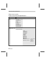
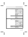
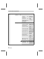
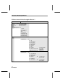
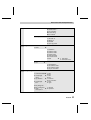
1
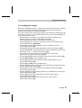
HART Hand-held Communicator for HART Positioner Type 3780 A B C D E F G H I 7 8 9 J K L M N O P Q R 4 5 S T U V W X 1 #%& 0 6 Y Z > . / 3 2 < * : + _ Fig. 1 ⋅ Type 3780 HART Positioner with hand-held communicator Operating Instructions EB 8380-3 EN Edition July 1999 Contents General information Contents Page 1. General information . . . . . . . . . . . . . . . . . . . . . . . . . . . . . 2 2. 2.1 2.1.1 2.2 2.3 2.4 2.4.1 2.4.2 Operation . . . . . . . . . . Start-up . . . . . . . . . . . Zero adjustment . . . . . . . Menu and key description . . Data entry . . . . . . . . . . Configuration and initialization Configuration example . . . . Initialization . . . . . . . . . 3. 3.1 3.2 Menu structure overview . . . . . . . . . . . . . . . . . . . . . . . . . Menu structure Device Description Revision 2 . . . . . . . . . . . . . . . . Menu structure Device Description Revision 1 . . . . . . . . . . . . . . . . . . . . . . . . . . . . . . . . . . . . . . . . . . . . . . . . . . . . . . . . . . . . . . . . . . . . . . . . . . . . . . . . . . . . . . . . . . . . . . . . . . . . . . . . . . . . . . . . . . . . . . . . . . . . . . . . . . . . . . . . . . . . . . . . . . . . . . . . . . . . . . . . . . . . . . . . . . . . . . . . . . . . . . . . . . . . . . . . . . . . . . . . . . . . . . . 3 3 3 4 4 6 7 11 12 12 16 1. General information The HART (Highway Adressable Remote Transducer) Communicator is a hand-held terminal for communication with HART-compatible field devices, such as SAMSON Type 3780 Positioner, which is equipped with an appropriate interface for the HART protocol. Data are transmitted by superimposing an FSK signal (FSK = Frequence-Shifting Keying) onto the current signal on the existing signal lines of the reference variable 4 to 20 mA at a minimum load resistance of 250 Ω (for load adjustment, see EB 8380-1 EN, chap. 3.2.2). The hand-held communicator is designed for field applications and allows users to configure connected field devices, request data and, in case of malfunction, diagnose errors any time via the HART protocol. Note: For handling and general operation of the HART Communicator, see the operating instruc tions supplied with each device. The description refers to the Hart Communicator Rosemount Model 275 for Device Descrip tion Revision 2. The update version Revision 2 is compatible with the preceding version Revision1. 2 EB 8380-3 EN Operation 2. Operation Before you can start operating the SAMSON Positioner, you have to load the SAMSON application program which can be ordered via the HART Communication Foundation (HCF). When using the [Í] key to go from the Online menu down to the submenu Utility> Simulation, you can view the list containing all the application programs presently stored in the communicator. 2.1 Start-up Supply the positioner with pneumatic power (air supply) and connect to the reference variable >4 mA. 2.1.1 Zero adjustment Important: If zero has not already been adjusted upon positioner mounting as described in the Moun ting and Operating Instructions EB 8380-1 EN, chap. 4.1, mechanical zero adjustment must be carried out with the valve being in closed position prior to initialization of the devi ce. 1. Push the zero lever (marked by an arrow and 0 symbol on the cover plate) once in the direction indicated by the arrow as far as it will go. For control valves with the position OPEN, i.e. actuators with "Actuator stem retracts", you must cover the bore on the cover plate marked by a hand symbol with your finger so that the valve moves in closing position. 2. Establish the connection between the HART Communicator and the positioner using the 2-pole communication line. 3. Use the key [I/0] to switch on the device. The display indicates for several seconds that a self-test is in progress. If you are connecting your hand-held communicator to a field device for the first time, a warm start is executed which you must acknowledge by pressing the function key [F3] [NEXT]. The display shows the base menu of the Type 3780 Positioner indicating online operation. EB 8380-3 EN 3 Operation 2.2 Menu and key description A maximum of five menu items can be displayed in numbered display lines. To access further menu items, press the [Ð] key or directly enter the line number [1] to [9] on the alphanumeric keypad. Since the line numbers can only be displayed as one-digit numbers, menu items above 9 are marked by Î and can be accessed via the [Ð] key only. In addition to the Main menu, there are further submenu levels in which data can be updated. An updated menu item is displayed reversely in the display line, an Î behind the line number signifies that the next menu level can be accessed by pressing the [Î] key. The labels located directly above the function keys show that keys software function, such as [HELP], [NEXT] or [HOME], for the current menu. To acknowledge an activated function, press the function key [F1] to [F4] that is located directly below the activated label. For example, in menus providing access to online help, the [HELP] label appears above the [F1] key. To view large texts that cannot be displayed entirely, press [PGUP] or [PGDN] . Use [EXIT] to terminate help. Alphanumeric keys [1] to [9] For direct selection of individual menu items (display line number), and for entering numerals. Arrow keys For data input, you must first press the corresponding arrow key to select one of the left, center or right letters or other symbols before you press the corresponding alphanumeric key. 2.3 Data entry Fields in which you can enter data are displayed reversely and the relevant digit position is blinking. You can access the digit position with the [Î] and [Í] key and delete it with the [DEL] function using the corresponding function key. Use [ESC] to leave the field unmodified without accepting the entered data. To store the entered data, select [ENTER]. Use [EXIT], to leave the current input field, and [BACK] to go to the previous field. Using [HOME] brings you back to the Online menu. Note: For more detailed information on the input fields, use the [F1] key to enter [HELP]. To obtain a list and description of the variables, refer to the List of parameters in the Mounting and Operating Instructions EB 8380-1 EN. 4 EB 8380-3 EN Operation 3780 :-/- Online menu Online Next menu Step down 48.5 % 2 x 48.4 % 3 x_d 0.1 % 4 Ð 5 Dynamic labels Í 1 Î w Previous menu Hand / Auto Information HELP F1 Function keys F4 F3 F2 Step up Communicator On /Off Zero adjustment Action keys Next menu Previous menu Step down Alphanumeric keys A B C D E F G H I 7 8 9 Shift keys EB 8380-3 EN 5 Configuration and initialization 2.4 Configuration and initialization The positioner is supplied with a basic configuration containing the default values (coldstart values). These settings or other potentially existing configuration data can be overwritten by entering a new data record. Note! The inner side of the hinged lid contains a slider for write protection. When in position 1, the settings of the positioner are write-protected and cannot be overw ritten by the HART protocol. To enable the hand-held communicator to overwrite the adjustment data, the slider must be set to 0. Basically, you should begin with entering the tag number, plant identification number as well as the current date in the menu Information > Device information to make them available to the positioner. The manufacturers actuator and valve identification number as well as the actuator type (linear or rotary actuator) and attachment (integral positioner attachment or according to NAMUR) must then be entered in the menu Information > Device type. Finally, you can enter the desired operational data in the menus Configuration, Characteristic and Parameters. If you intend to use the positioner in split-range mode, you must change the polling address in the menu Information > HART parameters from 0 (default) to 1 for the first valve or from 0 to 2 for the second valve. Finish configuration by starting the initialization procedure for the positioner in the menu Initialize. 6 EB 8380-3 EN Configuration and initialization 2.4.1 Configuration example Based on the SAMSON Type 3241-7 Control Valve, consisting of the Type 3241 Valve and the Type 3277 Actuator, connected to associated positioner over point-to-point line. Positioner version includes two software limit switches. The sequence of the concise description given below can be clearly seen with the help of the menu structure in chap. 3.1. From within the Online menu, you can access the different submenu levels via the line numbers. Deliver supply air to the positioner and connect to the reference variable >4 mA. Establish connections and switch on the HART Communicator. The connected positioner appears on the display in the Online menu. Press keys [2], [1], [1] in succession to enter the tag number in the input field [Tag]. Confirm with function key [F4] [ENTER]. Press key [5] to enter the plant identification number under [Description]. Confirm with function key [F4]. Press key [7] to enter the current date under [Date]. Confirm with function key [F4]. Press keys [Í], [2], [2] to enter the manufacturers actuator identification number under [Actuator ID no.]. Confirm with function key [F4]. Press key [3] to enter the manufacturers valve identification number under [Valve ID no.]. Confirm with function key [F4]. Press keys [Í], [3], [3] to enter 0 under [Poll addr]. Confirm with function key [F4]. Press key [F3] for [HOME] to return the Online menu. Press keys [4], [1], [1], [1] to select the linear actuator under [Actuator type]. Confirm with function key [F4]. Press key [F3] for [HOME] to return the Online menu. Press keys [4], [2], [1], [1] to enter the start value of the reference variable (4 mA) under [Start]. Confirm with function key [F4]. Press key [2] to enter the end value (20 mA) of the reference variable under [End]. Confirm with function key [F4]. Press keys [Í], [2] to select the operating direction (>>) under [Moving direction]. Confirm with function key [F4]. Press keys [3], [1] to adjust (1%) under [End position when below]. Confirm with function key [F4]. Press key [2] to adjust (125%) under [End position when above]. Confirm with function key [F4]. EB 8380-3 EN 7 Configuration and initialization Press keys [Í], [4], [1] to enter the start value (0.0 mm) under [Travel range start]. Confirm with function key [F4]. Press key [2] to enter the end value (15 mm) under [Travel range end]. Confirm with function key [F4]. Press keys [Í], [5], [1] to enter the desired travel limit (0.0 %) under [Travel limit lower]. Confirm with function key [F4]. Press key [2] to enter the desired travel limit (100 %) under [Travel limit upper]. Confirm with function key [F4]. Press keys [Í], [6], [1] to adjust [req. time open] by retaining the value 0.0 s or changing it as required. Confirm with function key [F4]. Press key [2] to adjust [req. time closed]by retaining the value 0.0 s or changing it as required. Confirm with function key [F4]. Press keys [Í], [7], [1], for error monitoring [Tol band], retain 5 % or change it as required. Confirm with function key [F4]. Press key [2] to adjust [Delay time] by either retaining 10 s or changing it as required. Confirm with function key [F4]. Press keys [Í], [8] to adjust [Valve travel limit]. Confirm with function key [F4]. Press key [9] to use [1], [2], [3] to choose the desired fault alarm functions by entering yes or no. Confirm with function key [F4]. Press keys [Í], [Ð], [Î] to adjust the operating direction (>>) for the position transmitter [Op.dir.pos.transm.]. Confirm with function key [F4]. Press keys [Ð], [1], [1] to adjust [Switch GW1 value] for the lower limit value GW1. Confirm with function key [F4]. Press key [2] to choose < = fall below, or > = exceed under [Switch 8 GW1 on at]. Confirm with function key [F4]. Press keys [Í], [Î], [2], [1], [1] to adjust [Switch GW1 value] for the upper limit value GW2. Confirm with function key [F4]. Press key [2] to choose > = exceed, or < = fall below under [GW2 on at]. Confirm with function key [F4]. Press key [F3] for [HOME] to return to the Online menu. Press keys [4], [3], [1] to select a characteristic. Default is linear, if needed, select another characteristic. Confirm with function key [F4]. EB 8380-3 EN Configuration and initialization Important: The valve characteristic is determined by the geometrical shape of the seat and plug. Ent ries you make in [Characteristic] modify the valves characteristic so that there is a resulta nt of both characteristics. You can switch between linear and equal percentage, equal percentage reverse and user-defined. When you select an equal percentage characteristic, it is copied into the user-defined characteristic, overwriting any previously entered user-defined characteristic! For a user-defined characteristic, you can enter optional coordinates via 11 paired values (refer also to table). Press key [F3] for [HOME] to return to the Online menu. Input and output values in % Point x y x y x y [0] 0.0 0.0 0.0 0.0 0.0 0.0 [1] 1.0 10.1 1.6 8.6 17.7 10.5 [2] 2.5 20.2 4.4 19.6 31.4 18.4 [3] 4.6 30.2 6.0 23.9 50.2 30.9 [4] 7.8 40.2 12.2 33.6 65.5 43.8 [5] 12.5 50.2 15.9 38.8 72.6 50.7 [6] 19.5 60.2 33.6 55.1 78.7 58.2 [7] 29.70 70.2 45.6 64.3 90.6 75.7 [8] 44.8 80.1 63.6 75.2 93.5 81.3 [9] 67.1 90.0 81.6 86.1 96.1 87.9 [10] 100.0 100.0 100.0 100.0 100.0 100.0 Examples Equal percentage reverse SAMSON butterfly valve Linear x y x y x y Add further user-defined values here Equal percentage The table lists the coldstart values for the user-defined characteristic (equal percentage reverse) in the first double column. The following double columns show user-defined values, e.g. for a Samson butterfly valve. EB 8380-3 EN 9 Configuration and initialization Press keys [4], [4] to access the parameters menu. We recommend that you retain the default settings, since they suffice most applications. Press key [1] to enter the proportional-action coefficient for supply air under [KP_Y1]. Retain the default value 1.20 or change it. Confirm with [F4]. Press key [2] to enter the proportional-action coefficient for exhaust air under [KP_Y2] . Retain the default value 1.20 or change it. Confirm with [F4]. Press key [3] to enter the gain factor under [KD] . Retain the default value 0.12 or change it. Confirm with [F4]. Press key [4] to enter the dead band under [Xtot]. Retain the default value 0.5 or change it. Confirm with [F4]. Press key [5] to enter the overshoot under [Tol oversht]. Retain the default value 0.5 or change it. Confirm with [F4]. Press key [6] to select pulse adaptation to be [automatic] or disabled. Confirm with [F4]. Press key [F3] for [HOME] to return to the Online menu. Data input has been completed. Now start the initialization routine for the positioner/valve assembly. 10 EB 8380-3 EN Configuration and initialization 2.4.2 Initialization Choose the menu [Device setup], select the menu item [Initialize] and start the initialization procedure for the connected positioner with [Start initialization]. Do not attempt to start the initialization procedure while a process is still in progress. During initialization, the control valve ldeparts from its current position at full trav el. Therefore, initialize the positioner in the start-up phase only when shut-off valves are closed or when removed and on the test bench. From within the Online menu: Press keys [4], [5] to access the Initialization menu. Press key [1] to start the initialization procedure. The warning text appears, confirm with [F4] [OK]. The procedure will take several minutes and is indicated by the message -running- on the display. Initialization can be stopped any time by pressing key [F3] [Abort]. When the message -successfull- appears, press key [F4] for [OK] and [F3] for [HOME], to finish the initialization procedure and return to the Online menu. The positioner is now ready for operation with the new data record. Initialization directly on the positioner An initialization carried out directly on the positioner is only possible for the first initialization routine. An already performed initialization can, nevertheless, be reset to coldstart values in the menu Diagnosis/Service >Status by choosing Reset. Perform the initialization procedure as described in the Mounting and Operating Instructions of the positioner EB 8380-1 EN, chap. 4.2.2. EB 8380-3 EN 11 Menu structure Device Description Revision 2 3. Menu structure overview 3.1 Menu structure Device Description Revision 2 Online menu 1 Submenus Process variables Î 1 Op. mode 2 Operating status 3 x (%) 4 w (%) 5 w_analog (mA) 6 e (w-x) 7 Fault alarm 8 SW_LimitSw GW1 9 SW_LimitSw GW1 Î Forced venting 2 Information Î 1 Device informationÎ 1 Tag 2 Manufacturer 3 Pos. type no. 4 Ex-proof type 5 Description 6 Message 7 Date 8 Serial no. 9 Text input 1 ÎText input 2 ÎText input 3 ÎText input 4 ÎSoftware revision Î ÎHardware revisionÎ 12 EB 8380-3 EN 1 Communication 2 Control 1 Electronics 2 Mechanics Menu structure Device Description Revision 2 2 Device-type 2 Î 1 2 3 4 Pos. product no. Actuator ID no. Valve ID no. Actuator Î 5 Attachment 6 Transmission Î 7 Rated travel/Nom. angle 8 Fail-safe action 9 Pos. transmitter ÎForced venting ÎLimit switches 1 Actuator type 2 Construction 1 Code Length Pin position 3 HART-Parameters Î 3 1 2 3 4 Universal rev Fld dev rev Poll addr Num req preams 1 2 3 4 5 Fault alarm SW_LimitSw GW1 SW_LimitSw GW2 Forced venting Total valve travel Î Diag/ServiceÎ 1 Status Î 2 Zero adjustment Î Î 3 Test device 6 Pulses Î 7 Write protect 8 Reset Î 1 Current value 2 Valve travel limit 1 Range 1 2 Range 2 3 Range 3 1 Control loop error 2 Total valve travel 3 Coldstart 1 Test fault alarm 2 Test swlimitsw GW1 3 Test swlimit sw GW2 4 Test pos. transmit EB 8380-3 EN 13 Menu structure Device Description Revision 2 4 Device setup Î 1 Start up Î 1 Actuator Î 2 Attachment 3 Transmission 1 Actuator type 2 Construction Î 1 Code Length Pin position 4 Rated travel/Nom. angle 5 Mount. position 6 Init. method 2 Configuration Î 1 Reference variableÎ 2 Moving direction 3 End position whenÎ 4 Travel/angle rangeÎ 5 Travel/angle limit Î 6 Req. transit time Î 7 Error monitoring Î 8 Valve travel limit 9 Fault alarm when Î Î Op. dir. pos. transm. Î Limit switches Î 14 EB 8380-3 EN 1 Switch GW1 Î 2 Switch GW2 Î 1 Reference var start 2 Reference var end 1 End pos when below 2 End pos when above 1 Travel range start 2 Travel range end 1 Travel limit lower 2 Travel limit upper 1 Req. time open 2 Req. time close 1 Tol band 2 Delay time 1 Alarm no comm possible 2 Alarm special mode 3 Alarm travel limit 1 Inductive limit Sw 2 Software limitsw 1 Switch GW1 value 2 Switch GW1 on at 1 Switch GW2 value 2 Switch GW2 on at Menu structure Device Description Revision 2 4 3 Characteristic Î 1 Charact. selection Î 2 Charact. type 3 Coordinates 4 Parameters 5 Initialize linear user defined % reverse % Î 1 2 3 4 5 KP_Y1 KP_Y2 KD Xtot TolOversht 1 2 3 4 Start initilization Initial warnung Fail-safe action Min. transit time Î Î 5 Poss. stroke/angle 1 Min. opening time 2 Min. closing time EB 8380-3 EN 15 Menu structure Device Description Revision 1 3.2 Menu structure Device Description Revision 1 Online menu Submenus 1 2 3 w/ w_manual (command variable) x (controlled variable) x_d (control deviation) 4 Manual/Auto Î 1 2 3 4 5 6 7 8 5 Mode w/w_manual w_analog x Fault alarm Swlimitsw GW1 Swlimitsw GW2 Forced venting InformationÎ 1 Device-info Î 1 2 3 4 5 6 7 8 9 Tag Manufacturer Pos. type no. Ex-proof type Description Message Date Serial no. Software revision Î ÎHardwareVersion Î 2 Device-type Pos. product no. Actuator ID no. Valve ID no. Actuator Î 5 Attachment 6 Transmission EB 8380-3 EN Communication Controller Electronics Mechanics Î 1 2 3 4 16 1 2 1 2 Î 1 Actuator type 2 Construction 1 Code/Length 2 Pin position Menu structure Device Description Revision 1 5 7 Rated travel/angle 8 Fail-safe action 9 Pos. transmitter ÎForced venting ÎLimit switches 3 HART-parameters Î 6 Diagnose Universal rev Fld dev rev Poll addr Num req preams 1 2 3 4 5 6 7 Fault alarm Swlimitsw GW1 Swlimitsw GW2 Forced venting Total valve travel Limit value travel Reset Î 1 2 3 4 Test fault alarm Test swlimitsw GW1 Test swlimitsw GW2 Test pos. transmitter Î 1 Status 2 Test 7 1 2 3 4 Î 1 Fault alarm 2 Total valve travel Î Konfigurierung 1 Command variableÎ 1 2 Î 1 2 Travel/angle range 2 Î 1 3 Op. direction 2 Î 1 4 Travel/angle limit 2 Start End Start End Positioner Pos. transmitter lower upper 5 Req. filling time 6 Req. venting time 1 closed at Î 2 opened at 7 Valve close/open at EB 8380-3 EN 17 Menu structure Device Description Revision 1 7 8 Error monitoring Î 1 Tol_band 2 Delay time 9 Limit switches 1 Inductive limitsw Î installed not installed 2 Swlimitsw 1 Switch GW1 1 Value 2 on at < or > v. Î 2 Switch GW2 1 Value 2 on at < or > v. 8 Characteristic Î 1 Charact. selection 2 Coordinates 9 ParametersÎ 1 2 3 4 5 Î Î x[0], y[0] to x[10], y[10] KP_Y1 KP_Y2 KD Xtot Pulse adaptation Initialization Î 1 Actuator 2 Attachment 3 Transmission Î 1 Actuator type 2 Construction Î 1 2 4 Rated travel/angle 5 Fail-safe action 6 Min. filling time 7 Min. venting time 8 Cycle time factor 9 Min. pulse filling ÎMin. pulse venting ÎInitialize Î 1 ÎZero adjustment Î 1 18 EB 8380-3 EN Code/Length Pin position Start initialization Start adjustment EB 8380-3 EN 19 EB 8380-3 EN S/C 07.99 SAMSON AG ⋅ MESS- UND REGELTECHNIK Weismüllerstraße 3 ⋅ D-60314 Frankfurt am Main Telefon (0 69) 4 00 90 ⋅ Telefax (0 69) 4 00 95 07 Internet: http://www.samson.de