1
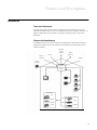
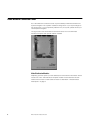
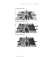
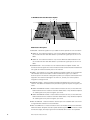
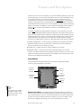
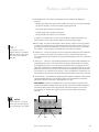
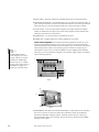
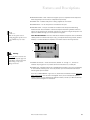
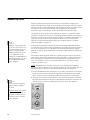
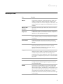
Home Network Connection Center Owners Manual ii First Edition January 1999 The following paragraph does not apply to any state or country where such provisions are inconsistent with local law: INTERNATIONAL BUSINESS MACHINES CORPORATION PROVIDES THIS PUBLICATION AS IS WITHOUT WARRANTY OF ANY KIND, EITHER EXPRESS OR IMPLIED, INCLUDING, BUT NOT LIMITED TO, THE IMPLIED WARRANTIES OF MERCHANTABILITY OR FITNESS FOR A PARTICULAR PURPOSE. References to IBM products, programs, or services do not imply that IBM intends to make them available outside the United States. This publication could contain technical inaccuracies or typographical errors. Changes are periodically made to the information herein; these changes will be made in later editions. IBM may make improvements and/or changes in the product(s) and/or program(s) at any time. Address comments about this publication to Product Support Manager -- IBM Home Director, IBM Corporation, 3039 Cornwallis Rd., Dept.XJQA, Research Triangle Park, NC 27709-2195 USA. Information you supply may be used by IBM without obligation. For copies of publications related to this product, call toll free 1-800-IBM-7282 in the Continental U.S.A. In Canada, call toll free 1-800-465-7999. Copyright International Business Machines Corporation 1999. All rights reserved. Note to U.S. Government Users - Documentation related to restricted rights -- Use, duplication, or disclosure is subject to restrictions set forth in GSA ADP Schedule Contract with IBM Corp. iv Notices vi Notices Notices References in this publication to IBM products, or services do not imply that IBM intends to make these available in all countries in which IBM operates. Any reference to an IBM product, program, or service is not intended to state or imply that only IBMs product, program, or service may be used. Any functionally equivalent product, program or service that does not infringe any of IBMs intellectual property rights may be used instead of the IBM product, program, or service. Evaluation and verification of operation in conjunction with other products, except those expressly designated by IBM, are the users responsibility. IBM may have patents or pending patent applications covering subject matter in this document. The furnishing of this document does not give you any license to these patents. You can send license inquiries, in writing, to the IBM Director of Licensing, IBM Corporation, 500 Columbus Avenue, Thornwood, NY 10594. General Information Intended Use. The IBM Home Network Connection Center is intended for use in standard residential construction. Supported system functions are listed in the IBM Official Published Specification for Home Director. Important Notice. Your IBM Authorized Home Systems Integrator, has installed this unit to meet FCC requirements. Modifying this unit beyond the original configuration can result in damage to your unit. If you have any questions concerning your system contact your IBM Authorized Home Systems Integrator. This product has been thoroughly tested and found to comply with the requirements listed in FCC Regulations, Part 15 for class B devices. Compliance with these requirements provides a reasonable level of assurance that your use of this unit in a residential environment will not result in harmful interference with other electronic devices. Option Availability. Options described in this document may not be available in all models of the Home Network Connection Center. For more information about options, please contact your IBM Authorized Home Systems Integrator. Safety Information Your Home Network Connection Center is installed by an IBM Authorized Home Systems Integrator with a specific configuration. If you require changes to the configuration or if you experience problems with your system, please contact your IBM Authorized Home Systems Integrator. To avoid possible hazards due to fire or electrical shock, only an IBM Authorized Home Systems Integrator should install or repair the unit. If you have any questions concerning option installation, configuration, or repair, contact your Home Systems Integrator. Notices vii Notices Trademarks The following terms are trademarks or registered trademarks of the IBM Corporation in the United States or other countries or both: IBM Home Director Other company, product, and service names may be trademarks or service marks of others. Microsoft, Windows, and the Windows 95 logo are trademarks or registered trademarks of Microsoft Corporation. Notices viii Notices Conventions used in this book Highlighting There are several ways that text is highlighted in this book. Each highlighting convention has a specific purpose. Highlight Purpose Bold Bold font is used to identify terms on the screen which you should click or double-click. Bold font is also used in headings, table titles, and numbered lists. Example Example font is used to show text that you need to type from your keyboard. Italic Italic font is used to show proper names of programs or books. Italic font is also used in table footnotes and sidenotes. Quotes Quotation marks are used to identify window, screen, and heading names. Underline Underline font is used to call special emphasis to a particular word or instruction. Conventions used in this book ix x Conventions used in this book Model Information xii Model Information Home Network Connection Center The following are lists of parts and features for the Home Network Connection Center. In some cases, model features and descriptions may change without notice or obligation by IBM. For further information on option availability, call your IBM Authorized Home Systems Integrator. Home Network Connection Center 3000 Package Residential Telcom Module Video Distribution Amplifier Computer Networking Module Camera Module Power Distribution Module DC Power Patch Cords (3) Network Connection Center Key Publications - Warranty, Registration Card Home Network Connection Center 2000 Package Residential Telcom Module Video Distribution Amplifier Power: DC Power Cord Network Connection Center Key Publications - Warranty, Registration Card Home Network Connection Center xiii xiv Home Network Connection Center Table of Contents vii Notices vii General Information vii Safety Information viii Trademarks ix Conventions used in this book ix Highlighting xiii Home Network Connection Center xiii Home Network Connection Center 3000 Package xiii Home Network Connection Center 2000 Package 3 Introduction 3 Terms used in this manual 3 Diagram of the Home Network 4 Home Network Connection Center - System Overview 4 Network Connection Center 4 Cables and Wires 5 Tap Points 5 Network Accessories 6 Home Network Connection Center 6 Video Distribution Modules 9 System Modules 14 Network Tap Points 15 Network Accessories 15 Video Camera 15 Satellite Dish 19 Glossary of Terms xv xvi Features and Descriptions 2 Features and Descriptions Introduction Terms used in this manual This manual provides you with basic information about the features of the Home Network Connection Center. For your convenience, there is a Glossary of Terms on page 19. Please refer to this section for questions concerning terms used in this document. Diagram of the Home Network This diagram shows how various systems and devices are connected to the Home Network Connection Center. The model you purchased may include some or all of these connections. Telephone Service Providers Antenna Digital Data Links Cable TV Providers Satellite Security Camera(s) Home Network Connection Center Television(s) Telephone Network Home Office Computer Network Fax VCR Modem Business Phones DVD IR Device 3 Home Network Connection Center - System Overview The Home Network Connection Center consists of four main network components: Home Network Connection Center Cables and wires* Network connections called Tap Points* Network accessories such as video cameras* *May be provided by your Home Systems Integrator. Network Connection Center The Home Network Connection Center (Connection Center) links the network together. All incoming signals generated from external sources (e.g., Cable TV or Satellite) enter the Connection Center and are distributed throughout the network. All outgoing signals generated from internal sources (e.g., CCTV or Telephone) are routed to the Connection Center and are either distributed throughout the system or sent out of the home. The Connection Center houses any one of four different Video Distribution Amplifier Modules (8 TAP, 8 TAP-Dual Cable, 16 TAP, and 16 TAP-DBS Satellite) and a power supply. The function of the Video Distribution Amplifier is to distribute signals across the network via coaxial cables connected to it. In addition to the Video Distribution Amplifier, there are other modules available for the Connection Center. These modules will be described in the section labeled System Modules on page 9. Cables and Wires To ensure consistent and reliable data transmission, only the highest quality cables and wires are used with the Connection Center. There are two types of cables that are used in the Connection Center: Series 6 Coaxial Cables (RG-6) Category 5 Twisted Pair Wires (Cat 5) The Connection Center uses these cables and wires to distribute signals throughout your home. The RG-6 cables distribute RF modulated television and high frequency satellite signals throughout the system. The Cat 5 wires distribute telephone and data signals throughout the system for your residential and home office telephones, fax machines, modems, and other devices. 4 Home Network Connection Center - System Overview Features and Descriptions Tap Points Tap points (taps) are wall-mounted connections in various places throughout your home. These taps are connected to the Home Network Connection Center by RG-6 cables and Cat 5 wires. Note Options described in this document may not be available in all models of the Home Network Connection Center. For more information about options, please contact your IBM Authorized Home Systems Integrator. Network Accessories Some models may include network accessories such as satellite dishes or cameras for the Television or CCTV Options. Refer to Network Accessories on page 15 for more information. Home Network Connection Center - System Overview 5 Home Network Connection Center Your Home Network Connection Center is pre-installed by an IBM Authorized Home Systems Integrator with a specific installation configuration. If you require changes to the configuration or if you experience problems with your system, please contact your Home Systems Integrator. This figure shows the Home Network Connection Center with a 16 TAP Video Distribution Amplifier and optional modules installed. Video Distribution Modules Depending upon the options you have selected, the Home Network Connection Center houses one of four video distribution amplifier models. The characteristics of each model and the function of each cable connection is described in Module Feature Descriptions on page 8. 6 Home Network Connection Center Features and Descriptions 8 TAP Video Distribution Amplifier. 1 2 3 9 4 8 6 7 5 8 TAP-Dual Cable Video Distribution Amplifier . 2 1A 1B 3 4A 9 4B 8 7 6 5 16 TAP Video Distribution Amplifier,. 1 2 3 4 9 8 Home Network Connection Center 7 6 5 7 16 TAP-DBS Satellite Video Distribution Amplifier 1 3 2 4 9 8 7 5 Module Feature Descriptions. 1 CATV/ANT Receives signals from your cable TV service provider or from an antenna. A CABLE A - This coaxial connector is only on the 8 TAP Dual Cable model and is for use in areas that have dual cable access. It provides the signal input for the A TV cable. B CABLE B - This coaxial connector is only on the 8 TAP Dual Cable model and is for use in areas that have dual cable access. It provides the signal input for the B TV cable. 2 CAMERA PORT This connector is on all video distribution amplifier models. This connector receives signals from the Connection Center Camera Module and distributes the signals to all external coaxial ports on the network. 3 SURGE This indicator is on all video distribution amplifier models. An illuminated red LED indicates that there has been an abnormal electrical surge on your cable or antenna system. This feature is designed to protect your computer and entertainment equipment from extensive damage. If the LED is lit, contact your Home Systems Integrator to arrange service. 4 EXTERNAL PORTS These connections distribute amplified output from the video network. The cables connected to them provide the signals to TV ports throughout your home. A CABLE A EXTERNAL PORTS - These coaxial connectors are only on the 8 TAP Dual Cable model and are for areas that have dual cable access. They distribute amplified A cable signals to TV ports throughout your home. B CABLE B EXTERNAL PORTS - These coaxial connectors are only on the 8 TAP Dual Cable model and are for areas that have dual cable access. They distribute amplified B cable signals to TV ports throughout your home. 5 DBS1 IN/ DBS2 IN - These connections receive input from a satellite dish. Use one for a single LNB dish and both for a dual LNB dish. 6 DBS1 OUT/DBS2 OUT - These connections are on all models except the 16 TAP DBS Video Distribution Amplifier that has a special satellite signal distribution feature. These connections supply the output signal from the satellite dish to one or two specified 8 Home Network Connection Center Features and Descriptions locations within the home. For example, if you have a satellite signal input at one of the IN connections [5], you may connect that cable to any one of the video cables that go out to various locations in your home. Therefore, when you connect a TV to the corresponding OUT terminal, that TV will be dedicated specifically for satellite signal reception. Other signals sent to the CATV/ANT port [1] or the INTERNAL connections [9] will dedicate all other locations in the home specifically for those signals. Connecting cables in this fashion will enable you to have televisions dedicated for either satellite reception or for the otehr signals (cable TV or antenna, and INTERNAL signals if provided). To have both satellite and antenna/cable TV reception on your televisions, you must have a 16 TAP-DBS Satellite Video Distribution Amplifier. This amplifier has a premium audio and visual amplifier feature that allows satellite signals to be distributed to every location throughout your home. For information about upgrading your system to allow satellite distribution to all locations and simultaneous viewing of different satellite channels at multiple locations, contact your IBM Authorized Home Systems Integrator. 7 POWER CONNECTION 15 volt DC power is supplied to the amplifier by the Power Distribution Module or from the junction box in the bottom of the Home Network Connection Center and is connected to this port. 8 POWER LED Indicates that power is being supplied to the module. 9 INTERNAL PORTS - These connections allow modulated signals into the video network. The cables connected to them distribute signals throughout your home. Any signals transmitted to these connections will be available at every external port, unless those ports are dedicated for satellite signals. System Modules The Home Network Connection Center houses various modules have specific functions, and are described in this section. Computer Network Module Camera Module Power Distribution Module Residential Telcom Module Note Some models may be installed with different module versions. Check with your Home Systems Integrator for details. Additional Module Plates Video Distribution Amplifier Residential Telcom Module. The Residential Telcom Module distributes all residential phone and data lines to various Telcom/telephone connections throughout your home. This module distributes up to four incoming residential lines that can be distributed to as many as twenty-four different locations throughout your home. In addition, each Telcom port is capable of accessing up to 2 of the 4 possible lines in various Home Network Connection Center 9 combinations, as indicated on the module face. A high speed data line may also be connected to this module. Note Phone line configurations can be rearranged and personalized according to your needs. To reassign an individual line or combination of lines at a specific tap point location, contact your IBM Authorized Home Systems Integrator. IMPORTANT NOTE: Depending upon the brand of phones you purchase or own, as well as the telephone service available in your local area, there is a limit to the number of phones that may be connected at any one time on any one line. The determination of the number of phones which may ring is dependent upon the R.E.N. (or Ring Equivalency Number). All phones have R.E.N.s (usually identified on a plate or embossed on the bottom of the phone). To determine your total R.E.N. in your household, find the R.E.N. for each phone connected to the same telephone line. Add the numbers together and this figure will be your R.E.N. A total per line R.E.N. of 5 is typically available through telephone companies for all residential service. Often, a total R.E.N. greater than 5 can be obtained without any noticeable service disruption. However, if you experience a problem with your phone service, reduce the total R.E.N. per line to 5 or less. Line banks, or columns, on the module are labeled. Standard single-line telephones have only a primary line available. Two-line phones will have both a primary and secondary line available from banks1 and 2. This section contains a description of the lines available at each port on the module. 8 6 5 7 4 1 Caution! If your Home Network Connection Center has a Residential Telcom Module, do not touch telephone cords when there is lightning in the area. 2 3 1 FIRST AND SECOND BANKS - These banks are designed for both two and one-line phone connections. For two-line phones, lines 1 and 4 are combined in these two banks, using Line 1 as the primary line and Line 4 as the secondary line. Up to twelve different taps can be connected to these banks to access both lines 1 and 4. Single-line phones can also be connected to these banks, but will only access line 1. 2 THIRD BANK- Line 2 is available in this bank. Only line 2 will be available at any tap port connected to a jack in this bank. Up to six different taps (phones) may be connected to this bank to access line 2. 3 FOURTH BANK- Line 3 is available in this bank. Only line 3 will be available at any tap port connected to a jack in this bank. Up to six different taps (phones) may be connected to this bank to access line 3. 10 Home Network Connection Center Features and Descriptions 4 LED INDICATOR This module is equipped with LED indicators for diagnostic purposes. • A bright green light at the top of a bank indicates an active line, or a line connected by your phone company. On-hook lines display a bright green light. • A dim green light indicates an off-hook line. • A flashing green light indicates a ringing line. • No light indicates an inactive or an unused line. To identify a line assignment, call one of the residential numbers assigned by your phone company. Then watch the LED display for the flashing green light. Note If you choose to convert a telephone data tap to an ISDN or ADSL line, that tap will no longer have access to any residential phone line. 5 RJ-31X JACK - This port can be used by a home security system monitoring company to make an emergency call using your primary phone line. Either a security panel or a shorting plug must be connected here in order to maintain a dial tone on your primary line number 1. (A shorting plug is included when the module is installed.) 6 LINE IN 1-4 - The incoming lines from your local phone company are color-coded blue (line 1), orange (line 2), green (line 3) and brown (line 4), and are carried from your service entrance through a single incoming larger blue Category 5 UTP wire, connected to this jack. 7 Cat 5 OUT - Data Out high speed digital data service can be made available at any voice/data tap point within your home either by having a dedicated tap port installed and plugged into this port, or by converting a residential line by unplugging the Cat 5 cable that is labeled for the telephone/data tap point youve chosen to convert to a high speed line and connecting it to the Cat 5 OUT jack on the Residential Telcom Module. For example, if you wanted to use a tap port in line 2 (Third Bank) for an ISDN line, you would (after having that tap converted to ISDN) plug that cable into the Cat 5 OUT port. 8 Cat 5 DATA IN - The Residential Telecom Module supports a separate incoming Cat 5 high-speed digital data line, such as ISDN or ADSL. All Home Network Connection Centers are wired for a data line to be plugged into this port. Camera Module. This option is available only on Connection Centers that have video distribution amplifiers installed. (Either 8 or 16 TAP). The Camera Module displays the Connection Center video monitoring camera(s) mounted throughout your home or surroundings. The module can support up to four cameras and has the following features: 1 Warning! Do not terminate or cap unused camera input connections. Doing so may cause damage to the module. 2 5 4 Home Network Connection Center 3 11 1 INPUT PORTS Each port receives a modulated signal from an individual camera. 2 LED SIGNAL INDICATOR This indicator allows you to quickly check camera status. A green LED light indicates an active and trouble-free camera. An unlit LED light indicates either that there is no camera assigned to that port or that the camera is inactive. 3 OUTPUT PORT This port sends camera signals to the video distribution amplifier module for distribution throughout your home. Camera signals can be received at all external TV connections on the network. 4 POWER INPUT 15 volt DC power is connected to this port. 5 POWER LED Indicates that power is being supplied to the module. Note Your IBM Authorized Home Systems Integrator may assist in setting up computers for network operation for an additional fee. Otherwise, refer to your computer operating system and your network card manual to configure your computers for network operation. Computer Networking Module. The Computer Networking Module connects up to four computer taps located throughout your home to a network. To utilize the computer networking module, each computer to be connected to your home network will require networking software, (refer to your operating system manual for configuring your computers for network use), as well as 10BASE-T network adapter cards (available either from your Home Systems Integrator or at computer supply stores). The module has the following features: 1 2 3 Front 4 5 Back 1 INDEPENDENT LINK AND COLLISION INDICATORS These green and red indicators allow you to monitor the network. Green lights indicate an active and trouble-free connection. Red lights indicate a collision, meaning that the network is busy (e.g., copying a large file across the network). As soon as network resources are available, the light will turn green. 12 Home Network Connection Center Features and Descriptions 2 NETWORK PORTS Each module can support up to four separate home computers. Each assigned port will connect to a separate computer tap. 3 POWER LED Indicates that power is being supplied to the module. 4 POWER INPUT 15 volt DC power is connected to this port. Note Make sure the patch cords are securely plugged in. If cords are not secure, Modules may not receive power. 5 CASCADE PORT This port is located on the back of the Computer Networking Module and can be connected to a second Computer Networking Module. With this option you can expand your computer network to a maximum of eight computers. This option is available through your Home Systems Integrator. Power Distribution Module. The Power Distribution Module uses patch cords to distribute 15VDC power to modules that require it (e.g., Computer Networking module, Camera Module, or a video distribution amplifier). The module has the following features: 1 2 Warning! Do not plug devices into this unit which are not expressly approved for the Home Network Connection Center. Doing so may cause damage to the unit. 1 POWER connections These connections, labeled A through F, connect to modules requiring power. Any module can be connected to any unused port. 2 POWER LED Indicates that power is available at the amplifier. The unit is protected by an automatically resetting fuse. This fuse protects your Home Network Connection Center against power trouble. If the red OVERCURRENT light turns on, disconnect all modules and then reconnect them one at a time. The red LED will reappear when you have located the problem module. When you have identified the problem module, contact your IBM Authorized Home Systems Integrator for assistance. Home Network Connection Center 13 Network Tap Points Tap points (taps) are wall-mounted connections in various places throughout your home. These taps are connected to the Home Network Connection Center by twisted pair wires (Cat 5) or coaxial cables (RG-6). These tap points may have a variety of ports that allow you to connect various devices such as telephones, fax machines, computers, TVs, or video cameras to your Home Network Connection Center. Note Modulators receive input from the specific device (video camera, etc.) and put the signals back onto the network on a specific channel. Modulators and necessary cables are not supplied but are sold separately by your IBM Authorized Home Systems Integrator. To order, call your IBM Authorized Home Systems Integrator. For example, an RJ-11 tap point for a telephone, fax machine, or computer modem provides a connection that can carry an internally-generated telephone call to either an external or internal source. An RJ-45 tap point provides a connection that enables one computer to communicate to other computers that are on your home computer network. For more information about setting up a computer network, Computer Networking Module on page 12. An RG-6 tap point provides a connection that carries externally-generated signals to your television set or VCR from the Home Network Connection Center. By connecting your TV to this tap point you may be able to view externally-generated TV, satellite, cable TV, or antenna signals depending on the model of video distribution amplifier you purchased. Some types of RG-6 tap points enable you to distribute signals internally. Certain tap points can be used to send signals (such as VCR, Laser Disc, or video camera) back to the Home Network Connection Center to be distributed to other tap points in your home. For example, from the TV in the master bedroom you can watch the VCR located in your family room. NOTE: Video signals sent through an internal port must be assigned to a specific channel through a modulator. Here are general guidelines for using an internal port. For specific instructions, refer to the instructions that came with your modulator. 1 Connect the base band video connections on your VCR, video camera, or Laser Disc (these connections will be identified as video out and will typically be color-coded yellow, white and red) to the base band video input connections on a modulator. EXTERNAL All unused external taps should be terminated with a terminator of appropriate resistance. For more information, contact your Home Systems Integrator. PHONE/ COMPUTER Taps shown in this manual may differ from the taps installed in your home. INTERNAL Note 2 Connect the output port of the modulator to the internal port tap point in that room. The signal will be sent back through the Home Network Connection Center. You can view the signal on any TV by selecting the channel you set on the modulator. Multitap 14 Network Tap Points Features and Descriptions Network Accessories Video Camera If your Home Network Connection Center is installed with a camera module, you can have up to four CCTV cameras mounted at designated areas (e.g., front door, nursery, play area, etc.). These cameras provide high-resolution black and white video with audio to any TV connected to a Home Network Connection Center TV port. Once installed, the cameras are always active. To monitor a designated area, turn on any television connected to a TV port and view the channel assigned for the desired camera. Camera channels are preset by your Home Systems Integrator. Your Home Systems Integrator should provide you with all camera channel designations. Note The 16 TAP-DBS Satellite Video Distribution Amplifier allows simultaneous local TV and optional satellite reception at any TV port using a splitter or diplexer available through your Home Systems Integrator. Satellite Dish If your Home Network Connection Center is installed with a Digital Broadcast Satellite (DBS) dish, a satellite decoder box is required for each television where you want satellite reception. Decoder boxes may be available from your Home Systems Integrator or most electronic supply stores. At the time of installation, your satellite dish should be connected directly to the video distribution amplifier in the Home Network Connection Center. Depending on the model installed, the video distribution amplifier can receive and distribute DBS video, audio, and satellite Internet services to either selected or all TV ports. Network Accessories 15 16 Network Accessories Glossary 18 Glossary Glossary of Terms Term Description 10Base-T The Ethernet standard for Local Area Networks (LANs). The 10Base-T standard (also called twisted pair Ethernet) uses twisted pair cables with maximum lengths of 100 meters. The system operates at 10 Mbps and uses baseband transmission methods. 10Base-T Cable Connectors Specialized connectors (8-pin RJ-45) that are at the ends of a Cat 5 wire. 10Base-T Network Adapter Card A specialized printed circuit board that plugs into a computer. It enables a computer to communicate with other computers or devices on a Local Area Network (LAN). ADSL Line Asymmetric Digital Subscriber Line. A high speed telephone line for Internet, intranet, and remote LAN access. Available in some areas. Camera Module A specialized printed circuit board mounted in the Home Network Connection Center that controls video monitoring cameras. Cascade Port A specialized port located on the back of the Computer Networking Module that allows connection of another Computer Networking Module that can expand network capacity to a maximum of 8 computers. Category 5 Wire Wires that transmit information in a computer network or telephone system. Cable is twisted pair, and each end of the wire has an 8-pin RJ-45 connector. One end plugs into a computer network card or telephone, and the other end plugs into computer or telephone tap mounted in a wall. Also called Cat 5 wire. CCTV Closed Circuit Television Coaxial Cable Electrical cables designed to transmit RF modulated television and high frequency satellite signals throughout the system. Also called RG-6 cable. Collision The result of two workstations trying to use a shared Cat 5 cable simultaneously. The signals bump into each other distrupting both signals. This disruption is represented by a red light at the Computer Networking Module. If a collision occurs, the signals are automatically transmitted again. The entire process takes a less than a second, and then the collision light will turn green. 19 Term 20 Description Computer Network A number of computers, printers, scanners, and other computer devices that communicate with one another through Cat 5 cabling and a shared protocol. Computer Network Module A specialized printed circuit board on the Home Network Connection Center that can connect up to 4 computers. DBS Direct Broadcast Satellite. A satellite system used in transmitting TV signals received by Home Satellite Dishes. Diplexer A device used to split combined incoming video signals according to frequency. It enables more than one video signal to be sent to a TV by assigning a signal to a specific channel. For example, high frequency satellite signals may be assigned to one channel and lower frequency TV signals may be assigned to another channel. Ethernet A specific type of Local Area Network (LAN) protocol. Ethernet is a widely implemented LAN protocol. ISDN Integrated Services Digital Network. A high speed telephone line for transferring large amounts of data at high speeds (64,000 bits per second). Local Area Network (LAN) A data communciations network spanning a limited geographical area (typically within a building). A LAN enables you to share disks, files, printers, and other devices under a form of standard control. LED Light Emitting Diode. Small lights (usually Red, Green, or Yellow) that indicate electrical activity. LED indicators are on many of the modules in the Home Connection Center LNB Low Noise Block Module A specialized printed circuit board used for a specific purpose. Modulator A device used to assign video signals to specific channels. Off-hook When a phone is in use, or off the hook. On-hook When a phone is not being used. Power Distribution Module A specialized printed circuit board mounted in the Home Network Connection Center that distributes 15VDC power to modules that require it. Residential Telcom Module A specialized multi-port circuit board mounted in the Home Network Connection Center that distributes all residential phone and data lines to various Telcom/telephone connections throughout your home. Glossary Term Description R.E.N. Ring Equivalency Number is the number of phones that can be connected at any one time and is usually found on the bottom plate of the phone. The R.E.N. varies according to the make and model of phone, as well as the phone service available. Surge An unusual increase in the current transmitted along an electrical line, which may happen during thunderstorms or other abnormal electrical events. Tap A specialized wall-mounted outlet (e.g., phone, computer, or video). Video Distribution Amplifier An 8-TAP or 16-TAP amplifier mounted in the Home Network Connection Center that receives, amplifies, and transmits signals across the Home Network. 21