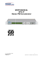
1
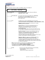
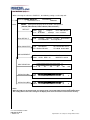
USER MANUAL SFD-IP Stereo FM Demodulator User manual PROFline SFD-IP 1 30032010GJdeR PROFline BV Specifications are subject to change without notice Contents: 1. General…………………………………………………………………………….…….…... 3 Installation………………………………………………………………………….………... 4 3. Operation…………………………………………………………………………………...... 5 3.1. Keypad…………………………………………………………………………….... 5 3.2. Display……………………………………………………………………………… .6 3.2.1. Default-mode……………………………………………………….……...6 3.2.2. MPX-deviation……………………………………………………………..7 3.2.3. Audio PM (dBu)……………………………………………………………7 3.2.4. Audio PM (dBFS)……………………………………………………….... 7 3.2.5. RDS default……………………………………………………………….. 8 3.2.6. RDS radiotext…………………………………………………………….. 9 3.2.7. Measurement……………………………………………………….…… 10 3.3. Menu structure……………..…………………………………………………………..11 4. Settings…………………………………………………………………………………………… 12 4.1.RF-in…………………………………………………………………………………………….. 12 4.2. Filter………………………………………………………………………………….. 12 4.3. MPX………………………………………………………………………………….. 13 4.4. Audio…………………………………………………………………………………. 14 4.5. Display……………………………………………………………………………….. 15 4.5.1. Mode……………………………………………………………………….. 15 4.5.2. Password…………………………………………………………………... 16 4.5.2. Contrast……………………………………………………………………. 16 4.5.3. Version……………………………………………………………………... 16 4.6. Name………………………………………………………………………….……… 17 4.7. Preset…………………………………………………………………………….….. 17 4.8. IP……………………………………………………………………………….…….. 18 4.9. Alarm…………………………………………………………………………….…… 20 4.9.0. Alarm general……………………………………………………………… 20 4.9.1. RF-in alarm………………………………………………………………... 21 4.9.2. Pilot alarm…………………………………………………………………. 22 4.9.3. RDS alarm…………………………………………………………………. 23 4.9.4. MPX alarm .……………………………………………………………….. 24 4.9.5. Audio alarm………………………………………………………………… 25 4.9.6. Log………………………………………………………………………….. 26 4.10. I/O……………………………………………………………………………………. 27 5. Connections……………………………………………………………………..…….….. 28 5.1. I / O Connectors……………………………………………………………….……. 28 6. Specifications SFD………………………………………………………………………. 29 7. RDS data output SFD……………………………………………………………….…… 32 8. Support……………………………………………………………………………….……. 34 9. CE-DECLARATION OF CONFORMITY……………………………………….….…… 35 10. WEEE Disposal Instructions……………………………………………………….….… 36 11. APPENDIX to SFD-IP Telnet session…………………………………………….……. 37 12. APPENDIX to SFD-IP WEB GUI.............................................................................. 37 13. APPENDIX to SFD-IP MP3 configuration................................................................. 39 1. GENERAL PROFline Thank you for selecting this fine piece of equipment. This user manual will help you in installing and operating this product on your network. The philosophy of PROFline is to develop and to produce equipment that is in conformity with the international standards, and is in no-way proprietary. In the last decade we have developed and User manual PROFline SFD-IP 2 30032010GJdeR PROFline BV Specifications are subject to change without notice produced digital- and analogue audio transmission products for a wide range of customers on the world market. The PROFline SFD is a “state of the art” broadcast quality FM demodulator with an extremely accurate reproduction capability. The demodulator is a total FM-demodulator system of which the input frequency can be freely selected within the 87.5 to 108 MHz band using the keypad on the front. The very high technical specifications of the SFD are combined with exceptionally stable characteristics. For many years now PROFline is preferred supplier for major global and local broadcast companies all over the world. FM Radio Demodulator SFD The SFD responds to the demands from the professional broadcast market. It is build around a high dynamic range FM-tuner with high selectivity, switchable wide and narrow IF bandwidth. The SFD is able to log 64 alarm events and has an extended range of alarm capabilities. For RDS-analyzing there are several RDS-monitoring functions available in the SFD. For further information, please contact PROFline. User manual PROFline SFD-IP 3 30032010GJdeR PROFline BV Specifications are subject to change without notice 2. INSTALLATION Before connecting the SFD to the mains, please check the unit for any traces of damage on mechanical or electrical parts. The SFD is a 19” 1U rack-mounting unit with connector access at the rear side. The power rating and heat generation are such that the unit can be placed in a 19” cabinet without special cooling facilities. However, sufficient clearance must be maintained between the SFD and other equipment (1U gap). If the other equipment generates a great amount of heat and/or the ambient temperature becomes too high, additional measures will have to be taken to dissipate the heat and guarantee reliable operation. The unit can be mounted at the front of a 19” rack using an appropriate mounting set. However, the use of lateral support is strongly recommended. Please check the following chapters when connecting the SFD in the application so maximum performance is guaranteed. Special care should be taken with respect to the safety regulations (earthing) as well as the proper mounting of the (RF) connectors. Warning! Do not attempt to open the SFD as there are no user-serviceable parts inside and warranty is void! For upgrading please contact PROFline or your local distributor. For contact information please refer to chapter 8 “Support”. User manual PROFline SFD-IP 4 30032010GJdeR PROFline BV Specifications are subject to change without notice 3. OPERATION The SFD was designed for professional use in broadcast environment and has a user friendly operating menu available through the keypad and display on the front side. The rear panel has also self-explaining connections and will be explained in chapter 5 “Connections”. 3.1. KEYPAD The buttons on the front, are function keys (← -menu). With the function keys all adjustments can be performed at the fronted of the SFD. F1 F1 F2 F3 F4 F5 ← ↑ ↓ ↵ = = = = menu = F2 F3 F4 F5 STOP INPUT / MENU BACK-STEP STEP RIGHT / INCREASE VALUE STEP LEFT / DECREASE VALUE CONFIRM (ENTER) OPEN MENU / CLOSE MENU To change settings and/or values, please perform the following steps. • Push on [menu] to select the menu function • Select the submenu (visible by flashing name) by pushing function keys ↑ and ↓. • Confirm the selection by pushing ↵ • Select the following submenu or setting (visible by flashing name) by pushing ↑ and ↓ • Put the SFD in the Editing mode by pushing ↵ the setting starts flashing • Now change the setting according to the manual by using ↑ and ↓, ← and ↵ confirm the new setting by pushing the ↵ button until the setting stops flashing (the name will now start flashing). • To leave the menu without storing the new value, please push on ← • When settings are performed push on ← to leave the submenu or push [menu] to return to the operating mode. In short: Step 1 Step 2 Step 3 Step 4 Call menu ([menu]) Select (↑, ↓, ← and ↵) Confirm by pushing ↵ button until setting stops flashing Close all menus [menu] or close sub menu (←) Step 2 and 3, depending of the value to be changed, are to be repeated several times. Attention! For quickly increasing or decreasing the settings, ↑ or ↓ should be hold for more than 1 second. After this period, value steps rapidly changes until the key is released. User manual PROFline SFD-IP 5 30032010GJdeR PROFline BV Specifications are subject to change without notice 3.2. DISPLAY When connecting the SFD to the mains, the unit will start up and after ± 4 seconds the selected display mode will appear on the display. 3.2.1. DEFAULT MODE * Program PFC: 240/100 kHz In: A 96.20 MHz 68 dBµV OUT: STEREO SFD [▄ ▄] SFD : Stereo Fm Demodulator, or Toggled with REMOTE when the SFD is remote controlled. [▄ ▄] : VU indication of received audio. When a stereo signal is received the VU indicator will show: [▄ ▄] in case of o mono signal it will show [▄ ] * : This symbol indicates the availability of RDS-data at the received frequency Program : Preset name or when RDS is available this shows the RDS-name. When the external MPX-input is selected by the user, the name will be toggled with MPX EXT. When the SFD is forced to the external MPX-input (with see chapter 4.3) this display will toggle with MPX EXT !, so here is the extra explanation point. Note: When the internal clock of the SFD is not set the display will only show SET CLK! PFC: 240/100 kHz : Setting of the Programmable Filter Configuration The indication is: IF-bandwidth (240) / AF-bandwidth (100) In: A 96.20 MHz : The input parameters are shown here, RF-input A, and input frequency 96,20 MHz If the input-level becomes lower than the MUTE-level (see chapter 4.1) the frequency will be toggled with the word MUTED. 68 dBµV : Level of the RF-signal at the selected RF-input OUT: STEREO : Gives information about the audio signals at the XLR-outputs (Mono or Stereo) User manual PROFline SFD-IP 6 30032010GJdeR PROFline BV Specifications are subject to change without notice 3.2.2. MPX-DEVIATION SFD ██████████████████████ █ kHz 0 20 40 60 80 100 SFD 160 : Stereo Fm Demodulator, or Toggled with REMOTE, when the SFD is remote controlled. This VU-meter displays a measurement of the deviation of the complete MPX-signal. This VU-meter has a peak hold function, which can be reset by pressing the ← button. 3.2.3. AUDIO PM (dBu) SFD dBu SFD L R █████████████████████ ▀ ▄ -31 -21 -11 -1 9 : Stereo Fm Demodulator, or Toggled with REMOTE, when the SFD is remote controlled. This VU-meter displays a measurement of the audio-level at the XLR-outputs. Note: When there is a stereo signal at the XLR-outputs, there will be two independent VU-indicators at the display. When the audio signals are mono, the VU meter will switch to one indicator, for Left and Right. 3.2.4. AUDIO PPM (dBFS) L SFD R █████████████████████ ▀ ▄ dBFS -40 -30 -20 -10 SFD 0 : Stereo Fm Demodulator, or Toggled with REMOTE, when the SFD is remote controlled. This VU-meter displays a measurement of the digital audio-level at the digital XLR-output. Note: When there is a stereo signal, there will be two independent VU-indicators at the display. When the audio signal is mono, the VU meter will switch to one indicator, for both Left and Right. User manual PROFline SFD-IP 7 30032010GJdeR PROFline BV Specifications are subject to change without notice 3.2.5. RDS DEFAULT SFD TA=YES TP=OFF PI=8203 DI=STEREO PS=Radio3FM PTY=Pop Music SFD : Stereo Fm Demodulator, or Toggled with REMOTE, when the SFD is remote controlled. TA= : Indication of received TA (Traffic Announcement) information (YES or NO) TP= : Indication of received TP (Traffic Program) information (ON or OFF) PI= : Received PI (Program Identification) information (4 digit hexadecimal number) DI= : The received DI (Decoder Identification control) PS= : Received PS (Program Service name) information PTY= : PTY (Program TYpe) information (MONO or STEREO) When one or more data-items are not available the display will show ----------- User manual PROFline SFD-IP 8 30032010GJdeR PROFline BV Specifications are subject to change without notice 3.2.6. RDS RADIOTEXT SFD MS=MUSIC RT=<Radio 3FM 24h> AF(A)=<95.20 MHz 95.8> CT=20:00 02-02-2002 SFD : Stereo Fm Demodulator, or Toggled with REMOTE, when the SFD is remote controlled. MS= : Music / Speech switch code AF= : Alternative Frequency . Both AF methods A and B are supported (automatically selected by the SFX) The displaying method of both AF-list methods differ from each other. These different methods are indicated with A or B by the SFX. Method A: This list is decoded in the background and all decoded data will be scrolled. If a new list is decoded the current list will finish scrolling and will be followed by the new one. Method B: This list is decoded in real time. After decoding one AF-list, the tuning frequency and the number of alternative frequencies is displayed. The alternative frequencies itself are not displayed! If the next AF-list is decoded, this one will be displayed. The SFX displays as many AF-lists in real time as possible, however it can skip displaying a list because they follow up each other too fast to display. RT= : The Radio Text will be scrolled here CT= : The received Clock and date information (Clock Time and date) When one or more data-items are not available the display will show ----------- User manual PROFline SFD-IP 9 30032010GJdeR PROFline BV Specifications are subject to change without notice 3.2.7. MEASUREMENT SFD SS= 69dBuV RDS= 1.9 kHz BER= 0% PILOT= 7.1 kHz MAX DEV= 62kHz SFD : Stereo Fm Demodulator, or Toggled with REMOTE, when the SFD is remote controlled. SS= : Signal Strength of the tuned frequency at the RF-input PILOT= : The measured Pilot (19 kHz) deviation of the received signal RDS= : The measured RDS (57 kHz) deviation of the received signal BER= : The Block Error Rate of the decoded RDS-data 0 % is error free MAX DEV= : Measurement of the maximum FM-deviation of the received program. This figure is the maximum (peak hold) deviation which can be reset by pressing the ← button. When the receiver frequency is changed, the peak-value will automatically be cleared. User manual PROFline SFD-IP 10 30032010GJdeR PROFline BV Specifications are subject to change without notice 3.3. MENU STRUCTURE Following diagram reflects the menu structure of the SFD SFD [▄ ▄] * Program In: A 96.20 MHz 68 dBuV PFC: 240/100 kHz OUT: STEREO ENTER PASSWORD: ******** MAIN | RF-IN FILTER MPX | NAME PRESET IP RF-IN This menu appears only when the password function is activated ! AUDIO DISPLAY ALARM I/O | FREQUENCY: 96.20 MHz INPUT: A | ATTENUATOR: AUTO MUTE: 30 dBuV FILTER | IF/MPX: 240 / 100 kHz (WIDE) | STEREO THRESHOLD: 35dBuV MPX | LEVEL: 6.0 dB PRE-EMPHASE: OFF | SRC: INTERNAL MODE: RDS AUDIO | LEVEL: 6.0 dBu TESTTONE:OFF | DE-EMPHASE: 50uS DISPLAY | MODE: DEFAULT | CONTRAST: 50 % NAME | EDIT: Program | COPY: <RDS-PS-name> PRESET | RECALL… | DEFAULTS IP User manual PROFline SFD-IP SAVE AS… | MAC LINK TCP/IP NAME DEFAULTS:NO | TELNET:ON SNMP:ON WEB:ON MP3:ON ALARM | | I/O PASSWORD VERSION RF-IN PILOT AUDIO RDS MPX LOG | INPUT [ 1 ]: FREQUENCY + 100 kHz | OUTPUT [ 1 ]: RDS PTY ALARM 11 30032010GJdeR PROFline BV Specifications are subject to change without notice 4. SETTINGS After pushing [menu] one time, the main menu will appear. The main menu will show all available submenus: MAIN | RF-IN FILTER MPX AUDIO DISPLAY | NAME PRESET IP ALARM I/O 4.1. RF-IN When selecting the submenu “RF-IN”, the following settings will become available: RF-IN | FREQUENCY: 96.20 MHz INPUT: A | ATTENUATOR: AUTO MUTE: 30 dBuV FREQUENCY : Receiver frequency (i.e.: 96.20 MHz) (87.5-108 MHz). INPUT : Selected RF-input (A / B) ATTENUATOR : Attenuation of the RF-input (0 – 40 dB or AUTO) MUTE : When the RF-input level becomes lower than this level, the RF-input will be muted. (1 – 50 dBuV or OFF) 4.2. FILTER The “FILTER” menu is responsible for the IF- and AF- filter settings. FILTER | IF/MPX: 240 / 100 kHz (WIDE) | STEREO THRESHOLD: 35dBuV IF/MPX : IF- and AF-filter settings 240 / 100 kHz (wide IF(240 kHz), full MPX (100 kHz)-processing) 180 / 100 kHz (small IF(180 kHz), full MPX (100 kHz)-processing) 180 / 15 kHz (small IF(180 kHz), mono MPX (15 kHz)-processing) STEREO THRESHOLD : RF-input level on which the filters will automatically switch back to 180/ 15 kHz (adjustable: 20-50 dBµV) The stereo threshold has an 5 dBuV hysteresis. i.e.: stereo threshold level = 30dBuV, the SFD will switch to mono (180/15 kHz) at 30dBuV, to switch back to the original settings, the SFD needs 35dBuV. User manual PROFline SFD-IP 12 30032010GJdeR PROFline BV Specifications are subject to change without notice 4.3 MPX When selecting the submenu “MPX”, the following settings can be adjusted: MPX | LEVEL: 6.0 dB PRE-EMPHASE: OFF | SRC: INTERNAL MODE: RDS LEVEL : Level of MPX-signal at the BNC-connectors (MPX-out) (adjustable 0 dB / +11 dB) PRE-EMPHASE : Pre-emphase filter for the External MPX-input. (ON / OFF) This option can be switched ON when there is a straight (not pre-emphased) –mono-audio-signal on the External MPX-input . SRC : The MPX-source used for modulating the PLL transmitter. INTERNAL/EXTERNAL(AUTO)/EXTERNAL(100kHz)/EXTERNAL (15kHz) Internal: The MPX-signal from the receiver-part is used for modulating the PLL transmitter. External (auto): The signal at the EXTERNAL MPX-input (Sub D15) is used for modulating the PLL transmitter. The filters of the SFP will be acting the same way as in the INTERNAL mode. So it will automatically switch at the Stereo threshold level, and the signal will be muted when it comes lower then the mute level. External (100 kHz): The signal at the EXTERNAL MPX-input (Sub D15) is used for modulating the PLL transmitter. The filters of the SFP will stay at 100 kHz so there will be an 100 kHz (full stereo) filter over the MPX-signal. The receiver will keep on working but the signal will not be muted and filters will no longer be switched automatically. External (15 kHz): The signal at the EXTERNAL MPX-input (Sub D15) is used for modulating the PLL transmitter. The filters of the SFP will stay at 15 kHz so there will be an 15 kHz filter (Mono) over the MPX-signal. The receiver will keep on working but the signal will not be muted and filters will no longer be switched automatically. Note: In internal mode it is possible to force the MPX-input to external. To do so, pin 15 of the sub D15 connector should be grounded. The display will show: SOURCE: FORCED EXTERNAL The MPX-filter will switch to 100kHz when FORCED EXTERNAL MODE User manual PROFline SFD-IP : Selects the type of RDS (Radio Data System) decoding. The SFD supports 2 different standards; - RDS (European) - RBDS (USA, Canada & Latin America) 13 30032010GJdeR PROFline BV Specifications are subject to change without notice 4.4. AUDIO When selecting the submenu “AUDIO”, the following settings can be adjusted: AUDIO | LEVEL: 6.0 dBu TESTTONE: OFF | DE-EMPHASE: 50 µs (-90 – 15 dBu) LEVEL : Audio output level at the XLR-connectors TESTTONE : Test tone of 500 Hz triangle waveform (ON – OFF) DE-EMPHASE : De-emphase of the audio signal (OFF - 50µs - 75µs) User manual PROFline SFD-IP 14 30032010GJdeR PROFline BV Specifications are subject to change without notice 4.5. DISPLAY (1/2) When selecting the submenu “DISPLAY”, the following settings can be adjusted: DISPLAY |MODE: DEFAULT | CONTRAST: 50 % 4.5.1. PASSWORD VERSION MODE: Setting of the display when the SFD is not operated ( Default, RDS default, RDS radiotext, Measurement ) DEFAULT: SFD [▄ ▄] * Program In: A 96.20 MHz RDS DEFAULT: SFD RDS RADIOTEXT: SFD MS=MUSIC RT=<Radio 3FM 24h> MEASUREMENT: MPX DEVIATION AUDIO PM (dBu) AUDIO PM (dBFS) PFC: 240/100 kHz 68 dBµV OUT: STEREO TA=YES TP=OFF PI=8203 DI=STEREO PS=Radio3FM PTY=Pop Music AF=<95.20 MHz 95.8> CT=20:00 02-02-2002 SFD SS= 69dBuV RDS= 1.9 kHz BER= 0% PILOT= 7.1 kHz MAX DEV= 62kHz SFD ██████████████████████ █ kHz 0 20 40 60 80 100 L R 160 █████████████████████ ▀ ▄ -31 -21 -11 -1 9 SFD R █████████████████████ ▀ ▄ dBFS -40 -30 -20 -10 0 SFD dBu L Note!: When the SFD is in the default mode, the display-mode can be adjusted by pushing the ↑ and ↓ buttons This setting will not affect the settings in the display-menu and is therefore not stored in the memory. User manual PROFline SFD-IP 15 30032010GJdeR PROFline BV Specifications are subject to change without notice 4.5.2 PASSWORD PASSWORD | PROTECTION: ENABLED | PASSWORD: PROFLINE PROTECTION: Protection for entering the menu interface. (ENABLED / DISABLED) PASSWORD: PROFLINE The password can be changed by the user, the maximum length of the password is 8 characters. To enter a shorter password, fill up to 8 characters with asterix (*) signs. (i.e.: TEST****) After enabling the protection and leaving the menu’s the following message will appear: EXIT MENU?: NO (PASSWORD PROTECTED) If it’s sure to leave the menu change NO to YES by use of the ↑ and ↓ buttons and press ↵ to confirm. Or press ← to return to the menu. Attention! Do not forget the password otherwise you will not be able to enter the SFD menu. DISPLAY (2/2) When selecting the submenu “DISPLAY”, the following settings can be adjusted: DISPLAY |MODE: DEFAULT | CONTRAST: 50 % 4.5.3. CONTRAST 4.5.4. : PASSWORD VERSION Display contrast setting ( 0 – 100 %) VERSION | | SERIAL SFD V0xx OPTIONS SERIAL=090929012 © PROFline ® : This will show the serial number of the SFD SFD V0xx : This will show the software-version of the SFD User manual PROFline SFD-IP OPTIONS | 1/3 | RX85_110.5 (NOT INSTALLED) (Hardware option) OPTIONS | 2/3 | IP2=V00X (Software option) OPTIONS | 3/3 | MP3 (Software option) (INSTALLED) (INSTALLED) 16 30032010GJdeR PROFline BV Specifications are subject to change without notice 4.6. NAME The submenu “NAME” incorporates the name settings for this program / preset: NAME | EDIT: Program | COPY: Radio3FM EDIT : The name of this program / preset can be entered here. This name will be displayed when there is no RDS(PS) name available. COPY : When there is a RDS(PS)-name available it will be shown here. By pushing the enter-button (↵) one time, (when COPY is flashing), the RDS(PS) name will be copied to the program/preset-name 4.7. PRESET The submenu “PRESET” displays the SFD preset management. PRESET | RECALL… | DEFAULTS SAVE AS… RECALL PRESET : The user can select a programmed preset, using the ↑ and ↓ buttons. This preset becomes active when pressing the enter (↵) key. The name of the selected preset is shown behind NAME= SAVE AS : This selection makes it possible to save the current SFD-configuration to a preset. Choose the right preset with the ↑ and ↓ buttons and press ↵ to confirm DEFAULTS : Active preset will be reset to factory defaults It’s recommended, when saving the variables from a program, to save also the name of this program (see submenu “NAME”). This gives the user, besides the preset number, an extra identification when using “RECALL PRESET” or “SAVE AS”. In Program and Recall mode, while stepping through the presets 1 to 64, the display will show the name of the program (preset). User manual PROFline SFD-IP 17 30032010GJdeR PROFline BV Specifications are subject to change without notice 4.8. IP The IP mode can be chosen to either DHCP or Manual. IP | MAC LINK TCP/IP NAME DEFAULTS : NO | TELNET: ON SNMP: ON WEB:ON MP3:ON (*) DEFAULTS :NO, YES IP, factory defaults are loaded (changing the setting results in a LAN port reboot) TELNET :ON, OFF Detailed IP application configuration see Appendix (changing the settings results in a LAN port reboot) SNMP :ON, OFF WEB :ON, OFF SFD remote control and measurement (changing the settings results in a LAN port reboot)The SNMP application note is available on request) MP3 (note *: Optional) :ON, OFF Enabling or disable the WEB GUI functionality (changing the settings result in a LAN port reboot) (see below information about the login) MP3 audio streamed over network The port number and IP address needs to be configured in TELNET (see appendix) Login username and password. The default values are for IP version below version 5 (1): Username: admin Password: password The default values are for IP version 5 and higher (1) (2): Username: admin Password: Pr0fl1ne (The symbol 0 is zero sign) Note 1: Please verify the IP version in the menu: MAIN DISPLAY OPTIONS OPTIONS 2/3 Note 2: In case you have upgraded the IP software to version 5, the WEB GUI password is not changed. We recommend to load the defaults after the upgrade, this will result in one password (Pr0fl1ne) for the Telnet and WEB GUI access. In the Telnet session you can change the password as required. User manual PROFline SFD-IP 18 30032010GJdeR PROFline BV Specifications are subject to change without notice MAC IP | ADDRESS=00-20-4A-9A-7C-71 | LINK IP | ETHERNETMODE : Auto-negotiation | ETHERNETMODE: TCP/IP IP Auto-negotition 100 Mbps Full-duplex 100 Mbps Half-duplex 10 Mbps Full-duplex 10 Mbps Half-duplex | MODE :DHCP | ADDRESS: 169.254.97.232 MODE :MANUAL, DHCP If DHCP is entered the LAN port will reboot and return to DHCP menu If MANUAL is entered the LAN port will reboot and following menu will appear TCP/IP IP | MODE :MANUAL SUBNET GATEWAY | ADDRESS: 169.254.97.232 ADDRESS :Enter the fixed IP address for the SFD SUBNET | HOST BITS : 8 TCP/IP | (SUBNET MASK=255.255.255.0) HOST BITS : Enter the number of host bits GATEWAY | GATEWAY : 255.255.255.0 TCP/IP | (0.0.0.0 will disable gateway) GATEWAY :Enter the gateway address NAME IP | DHCP : SFD 090929012← | DHCP User manual PROFline SFD-IP :A name can be edited with the up/down arrows. Default the name is linked with the serial number of the SFD. 19 30032010GJdeR PROFline BV Specifications are subject to change without notice 4.9. ALARM 4.9.0. ALARM GENERAL In order to receive an alarm on the relay outputs, make sure that the alarms are properly configured !!!! The following settings are available in the ALARM menus; MODE : OFF = Warning and Alarm are switched off : Warning Only = Warning light on the front will be activated : Warning+RelayA = Warning light on the front will light up and, after the alarm delay, the warning light will be changed into an alarm light and relay A will become active. : Warning+RelayB = Warning light on the front will light up and, after the alarm delay, the warning light will be changed into an alarm light and relay B will become active. : Warning+RelayC = Warning light on the front will light up and, after the alarm delay, the warning light will be changed into an alarm light and relay C will become active. WARNING DELAY = Delay in seconds before the warning light will be activated ALARM DELAY = Delay in seconds before the alarm light and relay will be activated Note! 1. Warning Delay is programmable between 0 and 599 seconds 2. Alarm Delay is programmable between 1 and 600 seconds The warning-delay should always be less then the alarm-delay. When the warning-delay is entered higher than the alarm-delay, the alarm-delay will automatically be set to the warning-delay-time + 1 second. User manual PROFline SFD-IP 20 30032010GJdeR PROFline BV Specifications are subject to change without notice 4.9.1. RF-IN ALARM The RF-IN alarm can be activated by two causes; (these each have their own menu’s) * RF-input level to LOW * RF-input level to HIGH ( 1 – 120 dBµV) ( 1 – 120 dBµV) Both alarm-levels can be configured individually. The alarm and warning delays can be adjusted in the sub-menu DELAY. ALARM | | RF-IN PILOT AUDIO ALARM RF-IN | LOW | RDS MPX LOG HIGH ALARM RF-IN | MODE: WARNING+RELAY A LOW |LOW<: 30 dBµV DELAY ALARM RF-IN | WARNING DELAY: 10 s LOW | ALARM DELAY: 30 s ALARM RF-IN | MODE: WARNING+RELAY A HIGH | HIGH>: 90 dBµV DELAY ALARM RF-IN | WARNING DELAY: 10 s HIGH | ALARM DELAY: 30 s User manual PROFline SFD-IP 21 30032010GJdeR PROFline BV Specifications are subject to change without notice 4.9.2. PILOT ALARM The PILOT alarm can be activated by a too low pilot-deviation. * Pilot level to LOW ( 0.1 – 15 kHz) The alarm and warning delays can be adjusted in the sub-menu DELAY. ALARM | | RF-IN PILOT AUDIO RDS MPX LOG ALARM PILOT | MODE: WARNING+RELAY A | LEVEL<: 6.0 kHz DELAY ALARM PILOT | WARNING DELAY: 5 s | ALARM DELAY: 10 s User manual PROFline SFD-IP 22 30032010GJdeR PROFline BV Specifications are subject to change without notice 4.9.3. RDS ALARM The RDS alarm can be activated by two causes; (these each have their own menu) * RDS level to LOW * BER to HIGH ( 0.1 – 6.0 kHz) ( 0 – 99 %) (RDS-deviation to LOW) (Block Error Rate of the RDS-data) Both alarm-levels can be configured individually. The alarm and warning delays can be adjusted in the sub-menu DELAY. ALARM | | RF-IN PILOT AUDIO RDS ALARM RDS | LEVEL MPX LOG BER | ALARM RDS | MODE: WARNING+RELAY A LEVEL | LEVEL<: 1.2 kHz DELAY ALARM RDS | WARNING DELAY: 10 s LEVEL | ALARM DELAY: 30 s ALARM RDS BER | MODE: WARNING+RELAY A | BER>: 50% DELAY ALARM RDS BER User manual PROFline SFD-IP | WARNING DELAY: 10 s | ALARM DELAY: 30 s 23 30032010GJdeR PROFline BV Specifications are subject to change without notice 4.9.4. MPX ALARM The MPX alarm can be activated by a too high MPX-deviation. * MPX-deviation to high: (0 – 159 kHz) Unlike other alarm’s, the MPX-alarm has no DELAY for activating the alarm, so the alarm will come up immediately after a too high MPX-deviation. The de-activating time for this alarm can be set in the delay menu. This means that in the period, entered in this menu, no exceeding of the MPX-deviation may occur in order to turn off this alarm. ALARM | | RF-IN PILOT AUDIO ALARM MPX DEVIATION MPX LOG | MODE: WARNING+RELAY A | LEVEL>: 70 kHz DELAY ALARM MPX DEVIATION User manual PROFline SFD-IP RDS | OFF DELAY: 10 s | 24 30032010GJdeR PROFline BV Specifications are subject to change without notice 4.9.5. AUDIO ALARM The AUDIO alarms can be activated by three causes; (these each have their own menu’s) All audio alarms are related to a lower audio deviation then entered in the menu! All three alarm-levels can be configured individually. * Level Left : (0 dB (40.0 kHz) -50dB (=0.14 kHz)) (monitoring of Left audio channel only) * Level Right: (0 dB (40.0 kHz) -50dB (=0.14 kHz)) (monitoring of Right audio channel only) * Level Both: (0 dB (40.0 kHz) -50dB (=0.14 kHz)) (monitoring of Left and Right audio-channel, this alarm will be activated if both Left and Right are below the alarm-level during entered delay-time) The alarm and warning delays can be adjusted in the sub-menu DELAY. ALARM | | RF-IN PILOT AUDIO ALARM AUDIO | LEFT | BOTH RDS MPX LOG RIGHT ALARM AUDIO | MODE: WARNING+RELAY A DELAY LEFT | LEVEL<:-40dB (=0.42 kHz) ALARM AUDIO | MODE: WARNING+RELAY A DELAY RIGHT | LEVEL <:-40dB (=0.42 kHz) ALARM AUDIO | MODE: WARNING+RELAY A DELAY BOTH | LEVEL <:-40dB (=0.42 kHz) ALARM AUDIO | WARNING DELAY: 10 s | ALARM DELAY: 30s User manual PROFline SFD-IP 25 30032010GJdeR PROFline BV Specifications are subject to change without notice 4.9.6 LOG The Log menu gives access to the following parameters ALARM | | RF-IN PILOT AUDIO LOG RDS | VIEW | CLEAR LIST:NO MPX LOG CLOCK VIEW LOG | ALARM RF-IN LVL LOW RAISED 5/64 | 12:00:13 02-02-2002 The log will show the alarms, which were Raised and Cleared. In the example the RF-IN level is dropped below the chosen level. The LOG-displays: ALARM RF-IN LVL LOW RAISED , with the time and date of the occurrence. (LVL = Level) The LOG is able to display the last 64 events. The LOG is made in a FIFO configuration, so the first event that occurred is the first that will be deleted from the LOG (after 64 events) Note: POWER ON and POWER OFF are also displayed in the LOG (with time and date) CLOCK | TIME: 12:10:42 OFFSET: 0.0h | DATE: 02-04-2005 LOCK TO: SNTP TIME: HH:MM:SS DATE: DD-MM-YYYY OFFSET: It is possible to give a time offset (for LOG use only). This can be used for a radio station that broadcasts a different time than the local-time (offset adjustable between -12 and + 12 hours). LOCK TO: To lock the internal clock to the time received from the RDS-data of SNTP (OFF / RDS / SNTP) CLEAR LIST: When selecting CLEAR LIST, the NO-sign will start flashing. If necessary change NO into YES with the ↑ and ↓ buttons and press ↵ to confirm. The Log list will now be emptied. The display will show: CLEAR LIST: (EMPTY) User manual PROFline SFD-IP 26 30032010GJdeR PROFline BV Specifications are subject to change without notice 4.10 I/O In the submenu “I/O”, the following settings can be set: I/O | INPUT [ 1 ]: FREQUENCY + 100 kHz | OUTPUT [ 1 ]: RDS PTY ALARM INPUT [1] : FREQUENCY + 100 kHz. When input 1 is ‘triggered’ the RF-input frequency will be set + 100 kHz. OUTPUT [1] : RDS PTY ALARM. When the PTY of the received station is switched to ALARM (PTY=31); output 1 will be set to high. Input’s and output’s each have four individual configurable in/output’s. These can be found at the SUB-D9 connector I/O at the backside of the SFD. Input settings make it possible to assign a SFD (internal) function to an input signal. The output is TLL compatible (0 to 5 Volt DC). Assignable input functions are: Input A/B Frequency + 10 kHz Frequency + 100 kHz Frequency - 10 kHz Frequency - 100 kHz Preset + Preset – Preset x ( x = 1 to 64 ) NOT USED The input will switch to the other RF-input The RF-input frequency will be increased with 10 kHz The RF-input frequency will be increased with 100 kHz The RF-input frequency will be decreased with 10 kHz The RF-input frequency will be decreased with 100 kHz The next preset will become active The previous preset will become active The SFD will switch to Preset x (which becomes active) No function assigned Input pulse, TLL compatible, falling edge sensitive, pulse length =>100 millisecond Output settings make it possible to assign a SFD (internal) measurement to an output signal. The output is TLL compatible (drive-level output: 20mA each port) Measurements available are: RDS TA When RDS TA-bit is set the output will be TRUE RDS TP When RDS TP-bit is set the output will be TRUE RDS TA & TP When RDS TA and the TP-bit are set the output will be TRUE RDS MS When RDS M/S-bit is set to Mono the output will be TRUE When RDS M/S-bit is set to Stereo the output will be CLEARED RDS PTY NEWS When RDS PTY is set to NEWS set the output will be TRUE RDS PTY ALARM When RDS PTY is set to ALARM set the output will be TRUE MPX MONO/STEREO When received signal is Mono the output will be TRUE When received signal is Stereo the output will be CLEARED NOT USED No function assigned User manual PROFline SFD-IP 27 30032010GJdeR PROFline BV Specifications are subject to change without notice 5. Connections From left to right: 1. Mains connection : IEC panel mount plug with fuse 2. I/O Connector : Sub D9 female (See 5.1 I/O Connectors) 3. Local Area Network : RJ-45 4. Digital output : XLR male (Impedance 110 Ω) 5. Audio output left : XLR male (Impedance is 600 Ω) 6. Audio output right : XLR male (Impedance is 600 Ω) 7. RDS DATA-connector : Sub D9 female (See 5.1 I/O Connectors) 8. I/O & Alarms connector: Sub D15 male (See 5.1 I/O Connectors) 9. MPX-output 1 : BNC 10. MPX-output 2 : BNC 11. Audio left & right : RCA-Cinch 2x 12. RF-input B : BNC 75 Ω 13. RF-input A : BNC 75 Ω 14. Ground chassis : M6 5.1. I/O Connectors I/O connector TTL 9-pole sub-D female connector: 1 : input #1 2 : input #3 3 : Ground 4 : output 2 5 : output 4 Data connector 9-pole sub-D female connector: 1 = 4 = 6 (Connected) 2 : Data out 3 : Data in 5 : GND AUDIO LEFT/RIGHT (XLR male) 1 : ground 2 : signal + 3 : signal I/O & Alarms connector 15-pole sub-D male connector: 1 : RELAY C Common 2 : RELAY C NO 3 : RELAY B NC 4 : RELAY A Common 5 : RELAY A NO 6 : MPX-OUT 7 : SCA-IN 8 : MPX-IN 9 : RELAY C NC 10 : RELAY B Common User manual PROFline SFD-IP 6 7 8 9 : : : : input #2 input #4 output 1 output 3 7 = 8 (Connected) 9 : n.c. Digital output connector (XLR male) 1 : ground 2 : signal + 3 : signal - 11 12 13 14 15 : : : : : RELAY B NO RELAY A NC ground ground MPX-FORCE-IN Alarm= Common and NO No alarm= Common and NC 28 30032010GJdeR PROFline BV Specifications are subject to change without notice 6. Specifications SFD RF unit Frequency input RF tuning stability RF input sensitivity RF inputs, main and spare Return loss Selectivity Narrow: Selectivity at ± 90 kHz Selectivity at ± 200 kHz Selectivity at ± 300 kHz Selectivity at ± 400 kHz Selectivity at ± 300 kHz Wide: Selectivity at ± 120 kHz Selectivity at ± 200 kHz Selectivity at ± 300 kHz Selectivity at ± 400 kHz Selectivity at +/-300 kHz Image rejection IF rejection AM rejection at 30% AM/75 kHz dev. RF Attenuation Adjacent channel suppression Muting threshold Stereo threshold Channel separation (Wide) Channel separation (Narrow) : Fully adjustable from 87.5 to 108 MHz, 10 kHz steps : < 500 Hz : 5 to 110 dBµV : 2 x BNC, 50/75 Ohm : >20 dB : >-3 dB : >-54 dB : >-95 dB : >-110 dB : Iw/Iu =-40 dB(mono) (*) : >-3 dB : >-30 dB : >-65 dB : >-100 dB : Iw/Iu = -23 dB(stereo) (*) : >100 dB : >110 dB : >72 dB : Automatic or manual : See selectivity specs : On/Off or adjustable 0 - 50 dBµV : Adjustable 20 - 50 dBµV : >48 dB 1 kHz typical >50 dB : >45 dB 100 Hz-500 Hz : >30 dB 10 kHz-15 kHz : >30 dB 1kHz Note *: Iw/Iu means the relation between the Input wanted signal and Input uwanted signal Stereo decoder Audio level adjustments L&R L/R separation Phase De-emphases 19 kHz suppression Distortion S/N 1 kHz (at 75 kHz deviation) RMS 20Hz-20 kHz QP CCIR S/N 1 kHz (at 40 kHz deviation) RMS 20Hz-20 kHz QP CCIR Audio main output Output impedance Audio frequency Phones MPX-output level MPX output impedance MPX output connector Digital output Test tone output, 500 Hz User manual PROFline SFD-IP : from -90 dB to 15 dB(steps 0.1 dB) : > 46 dB (1 kHz mod. / 40 kHz dev.) typ.> 50 dB : < 5º, 40 Hz -15 kHz : Adjustable 0-50-75µsec : > 50 dB : < 0.2%,1 kHz mod. / 40 kHz dev. : > 75 dB mono, >73 dB stereo : > 70 dB mono, >65 dB stereo : > 72 dB mono, >70 dB stereo : > 70 dB mono, >65 dB stereo : XLR male, 1=GND 2=+ signal 3=- signal : 20 Ohm balanced : 20 Hz-15 kHz, ± 0,3 dB: ref=500 Hz /40 kHz deviation/ 6 dBu : Stereo jack 6.3 mm on frontpanel,150 Ohm, 50µS de-emphasis : from 0 dB to 11 dB(0,1 dB steps) : normal termination 600 Ohm : minimum termination 75 Ohm : 2 BNC connectors : AES EBU ,XLR balanced : 500 Hz triangle 29 30032010GJdeR PROFline BV Specifications are subject to change without notice Measurement functions Large VU audio input (pm -dBFS) MPX deviation level RF level Pilot level 19 kHz RDS level 57 kHz RDS BER level RDS applications Alarm logging : -60 dBFS to 0 dBFS : from 0 to 160 kHz (step 1 kHz) : from 0 to 120 dBµV : from 0 to 15 kHz(step 0.1 kHz) : from 0 to 6 kHz(step 0.1 kHz) : from 0 to 100%(step 1 %) : MS, CT ,RT, AF, PS, PI, DI, TA, TP, PTY, Clock : 64 level deep logging of alarms are stored in a FIFO memory Management functions TELNET : Basic network settings and basic SNMP settings SNMP ( Simple Network management Protocol ) : V1 and V2c supported WEB : Remote control access over IP Optional MP3 streaming User manual PROFline SFD-IP : MP3 audio streamed over network : configuration in TELNET 30 30032010GJdeR PROFline BV Specifications are subject to change without notice Data and Alarm ports rear panel I/O connector RDS data port MPX input MPX input pre-emphasis RDS/SCA input MPX output nr 3 Alarm connection (relay contacts) : TTL compatible (drive level output: 20mA each port) input level 0-5Vdc : RS 232 protocol: UECP (RS 232) : via SUB-D15 impedance 600 Ohm. : 0 µsec for stereo use , or 50 µsec for mono use : impedance 600 Ohm : 600 Ohm for monitoring of receiver input : Sub-D25 connector female Alarm set up, menu-controlled Audio level MPX deviation level RF level Pilot level 19 kHz RDS level 57 kHz RDS BER level : Alarm choice A/B/C delay 1 to 600 seconds : -50 dB to 0 dB (step 1dB ) for Right or Left channel : from 0 to 160 kHz (step 1 kHz) : min RF/max RF from 1 to 119 dBuV : from 0 to 15 kHz (step 0.1 kHz) : from 0 to 6 kHz (step 0.1 kHz) : from 0 to 100% (step 1 %) General Main power Power connection Headphones connection Safety and EMC Operation ambient temperature Housing dimensions, weight : 100 to 240 VAC, 50 to 60 Hz, maximum 30 Watt : IEC panel-mount plug filter with fuse 2.5 AT : Stereo jack 6.3 mm : In accordance to CE regulations : 5 to 45 ºC (storage -5 to 65 ºC) : 19 inch x 1u x 300 mm (depth), 5 kg Specifications are subject to change without notice. User manual PROFline SFD-IP 31 30032010GJdeR PROFline BV Specifications are subject to change without notice 7. RDS data output SFD SFD Tuner RDS decoder UECP packetizer Filtered RDS in specific MEC’s PI, PS, TA_TP, DI, MS, PTY, RT All RDS in Free Format SFD Display + RS 232 SFDx Serial output 9 p D-connector (pin 2) Table with RDS messages and MEC’s as defined in the UECP 6.01. RDS message PI (Programme identification) PS (Programme service name) TA_TP (Traffic-announcement Traffic-programme identification) DI (Decoder identification) MS (Music/speech switch) PTY (Program Type) RT (Radio Text) FF (Free-Format) MEC 0x01 0x02 0x03 0x04 0x05 0x07 0x0A 0x24 At the next page the Free-Format group format and convention is explained as described in the UECP final version 6.01. (copyright RDS Forum, Geneva, Switzerland). User manual PROFline SFD-IP 32 30032010GJdeR PROFline BV Specifications are subject to change without notice User manual PROFline SFD-IP 33 30032010GJdeR PROFline BV Specifications are subject to change without notice 8. Support For support, please contact your local PROFline representative or contact our service department. Marga Klompélaan 18 6836 BH ARNHEM The Netherlands Phone : +31-(0)26 3236969 Fax : +31-(0)26 3233952 Web site : www.profline.nl e-mail : [email protected] User manual PROFline SFD-IP 34 30032010GJdeR PROFline BV Specifications are subject to change without notice 9. CE-DECLARATION DECLARATION OF CONFORMITY The undersigned hereby declares, on behalf of; PROFline B.V. Marga Klompélaan 18 6836 BH Arnhem The Netherlands that the following product; Equipment : Stereo FM Demodulator Model name : SFD to which this declaration relates, is in accordance with the following Directives: : EMC-Directive Directive 89/336/EEC has been designed and manufactured to the following specifications: Number : Title EN 60730-1 : Automatic electrical controls for household and similar use, Part 1: general requirements (February 1995), inclusive amendments A11 + A12 dated February 1996. EN 50081-1 : Electromagnetic compatibility – Generic emission standard Part 1: Residential, commercial and light industry. EN 50082-1 : Electromagnetic compatibility – Generic immunity standard Part 1: Residential, commercial and light industry. EN 55013 : Limits and methods of measurement of radio interference characteristics of sound and television evision broadcast receivers and associated equipment. EN 50020 : Limits and methods of measurement of immunity characteristics of sound and television broadcast receivers and associated equipment. I hereby declare that the equipment named above has been designed to comply with the relevant sections of the above referenced specifications. The unit complies with all essential requirements of the Directives. Signed by: Frank Peters Sengers, Sengers Managing Director Signature: th Arnhem, August 18 , 2009 User manual PROFline SFD-IP 35 30032010GJdeR PROFline BV Specifications are subject to change without notice 10. WEEE Disposal Instructions Disposal Instructions Do not dispose of this device with unsorted household waste. Improper disposal may be harmful to the environment and human health. Please refer to your local waste authority for information on return and collection systems in your area. Directives de mise au rebut Ne mettez pas cet appareil au rebut avec les déchets ménagers non triés. La mise au rebut incorrecte peut être nocive à l’environnement et à la santé humaine. Veuillez vous renseigner auprès des autorités compétentes de votre localité sur les procédures de renvoi et de collecte dans votre région. Instruzioni per lo smaltimento Smaltire questo dispositivo solo in un contenitore previsto per la raccolta municipale di rifiuti separata. Uno smaltimento improprio può inquinare l’ambiente ed essere pericoloso per la salute delle persone. Per informazioni sui centre di raccolta locali rivolgersi alle autorità locali competenti per lo smaltimento dei rifiuti. Instruções de disposição Não disponha a eliminação deste dispositivo como resíduo municipal não classificado. Disposição imprópria pode ser danosa ao meio-ambiente a à saúde de seres humanos. Por gentileza consulte a sua autoridade local de eliminação de resíduos para informações sobre os sistemas de retorno e coleta na sua área. Instrucciones de deshecho No tire este dispositivo en los contenedores municipales de basura no clasificados para reciclaje. Tirar residuos inapropia-damente puede resultar nocivo para el medio ambiente y para la salud de las personas. Por favor diríjase a las autoridades locales responsables de la eliminación de residuos para obtener información sobre los sistemas de devolución y recolección en su área. Anweisungen für die Entsorgung Dieses gerät darf nicht mit unsortiertem hausmüll entsorgt werden. Eine unangemessene Entsorgung kann sich schädlich auf die Umwelt und die Gesundheid auswirken. Bitte beachten Sie die Hinweise der für Ihren Ort zuständigen Behörden zu Rückgabe und Sammelverfahren. User manual PROFline SFD-IP 36 30032010GJdeR PROFline BV Specifications are subject to change without notice APPENDIX to SFD-IP Telnet session Basic knowledge of IP is expected to understand and use the next information. A Telnet session is only possible when: a) the Telnet application is switched ON. This can be done in the menu MAIN-IP b) the IP address is known. You can find the IP address in the menu MAIN-IP-TCP/IP. c) Telnet-client is available. Microsoft supplies the Telnet client with the Operating System. Below you will find all the necessary steps to start a Telnet Session in conjunction with the SFD-IP When the SFD-IP is switched to the “manual mode” the default IP address is 192.168.0.1. To make a Telnet connection with the SFD-IP you type: “telnet 192.168.0.1” behind the prompt. When the SFD-IP is switched to the “DHCP” mode you can find the IP address in the menu: MAIN-IP-TCP/IP. APPENDIX to SFD-IP WEB GUI Basic knowledge of IP is expected to understand and use the next information. Using the WEB GUI is only possible when: a) The WEB application is switched ON. This can be done in the menu MAIN-IP or in a Telnet session (see the APPENDIX Telnet session) b) The IP address is known. The IP address can be found in the menu MAIN-IP-TCP/IP. c) Web browser is available, we recommend to use Internet Explorer version 6 or 7. Be informed that menu’s, sub menu’s settings and measurements that are available via the front panel of the unit are also available via this WEB GUI (excluding the IP and Display menu). The names of menu’s and submenus, settings and measurements are the same as shown at the LCD of the SFD-IP. Detailed description of menu’s and settings can be found in this user manual. User manual PROFline SFD-IP 37 30032010GJdeR PROFline BV Specifications are subject to change without notice To open the WEB GUI with the Explorer, type the IP address of the unit into the address bar. The following screen will appear. Login username and password. The default values are for IP version below version 5 (1): Username: admin Password: password The default values are for IP version 5 and higher (1) (2): Username: admin Password: Pr0fl1ne (The symbol 0 is zero sign) Note 1: Please verify the IP version in the menu: MAIN DISPLAY OPTIONS OPTIONS 2/3 Note 2: In case you have upgraded the IP software to version 5, the WEB GUI password is not changed. We recommend to load the defaults after the upgrade, this will result in one password (Pr0fl1ne) for the Telnet and WEB GUI access. In the Telnet session you can change the password as required. User manual PROFline SFD-IP 38 30032010GJdeR PROFline BV Specifications are subject to change without notice Appendix MP3 configuration 1. Is the MP3 option installed? This document assumes that the MP3 option is installed. You can verify this in the menu: MAIN DISPLAY VERSION. 2. Configuration of the MP3 settings Before the MP3 option can be configured for your system be sure that the options TELNET and MP3 are enabled (=ON) in the menu MAIN IP (accessible via the front panel). Furthermore check the network address of the SFD-IP in the menu MAIN IP TCP/IP. 2.1 Open a MS-DOS command prompt on a personal computer inside the same network segment as the SFD-IP device. 2.2 Execute the telnet application using the command: telnet <network address> (i.e. telnet 192.168.1.100). 2.3 When the telnet session is connected, the SFD-IP will ask for an user account and password. The login and password depend on the IP version. The IP version is shown on the second line, in the picture the IP version is V005. The default values are for IP version 5 and higher: Username: admin Password: Pr0fl1ne (The symbol 0 is zero sign) The default values are for IP version below version 5: Username: admin Password: password 2.4 After login, The telnet command prompt (SFD>) is shown and ready to use. Type “mp3” followed by enter key, to open the mp3 configuration menu. 2.5 The three settings can be changed as required. Changes are only saved when the telnet session is closes with the command “save”. MP3 : Enable or disable Dest. Address : this can be a network broadcast address or a unicast address (see below network diagrams on the next page. Dest. Port : port number free to choose (please make sure that firewalls and routers in the network accept this port number. User manual PROFline SFD-IP 39 30032010GJdeR PROFline BV Specifications are subject to change without notice 3. Network diagrams Local IP network with MP3 streamer in a unicast solution. SFD-IP with MP3 option 1) SFD-IP address: 10.0.0.11 2) MP3 streamer 2.1) Destintation address: 10.0.0.17 2.2) port number: 5004 IP network 10.0.0.X Computer with MP3 player 1) Network address: 10.0.0.17 2) MP3 player 2.1) source address: 10.0.0.11 2.2) port number: 5004 Local IP network with MP3 streamer in a broadcast solution. SFD-IP with MP3 option 1) SFD-IP address: 10.0.0.11 2) MP3 streamer 2.1) Destintation address: 10.0.0.255 2.2) port number: 5004 IP network 10.0.0.X Computer with MP3 player 1) Network address: 10.0.0.17 2) MP3 player 2.1) source address: 10.0.0.11 2.2) port number: 5004 WAN solution MP3 streamer in a unicast solution. LAN SFD-IP with MP3 option 1) SFD-IP address: 10.0.0.11 2) Gateway address: 10.0.0.1 2) MP3 streamer 2.1) Destintation address: 187.0.0.25 2.2) port number: 5004 User manual PROFline SFD-IP Router WAN address: 187.0.0.20 WAN OR public Internet LAN Router WAN address: 187.0.0.25 Assign port 5004 to 10.0.017 Computer with MP3 player 1) Network address: 10.0.0.17 2) MP3 player 2.1) source address: 187.0.0.20 2.2) port number: 5004 40 30032010GJdeR PROFline BV Specifications are subject to change without notice 4. Audio player We like to introduce two audio players that can be used for the MP3 streaming application. • VLC (VideoLan) • Zinf 4.1 VLC VLC is a product of VideoLan (www.videolan.org), be aware that you need VLC media player 0.8.6b, for some reason the newer versions do not work (see below the “about” information). After installation and activating the application, the following window will appear: Open File menu 4.1.1 Configure the stream Open the File menu and you get a drop down menu, select “Open Network Stream”. The below tabs will appear, Select the Network tab, select UDP/RTP, edit the port number you have defined in the SFD-IP (Telnet session) and press ok. Enter: port number User manual PROFline SFD-IP 41 30032010GJdeR PROFline BV Specifications are subject to change without notice 4.1.2 Stream and Media info Open the menu View, select Stream and Media Info, the following information becomes available. 5. Zinf Information about this product can be found at www.zinf.org. After installation and executing the application the following window will appear (see next page): User manual PROFline SFD-IP 42 30032010GJdeR PROFline BV Specifications are subject to change without notice Select Files menu 5.1 Configure the stream Select the Files menu and the following window will appear with the possibility to open a URL. Edit the URL rtp://<source address>: <port number> (or rtp://@:5004). • • The destination address is the IP address of the SFD-IP, check the network address of the SFD-IP in the menu MAIN IP TCP/IP. Port number, this is the port number defined in the Telnet session. Enter: rtp://<source address>:<port number> Or rtp://@:5004 ___________________________________________________________________________ This publication contains information proprietary and confidential to PROFline BV. Any reproduction, disclosure, or dissemination of this publication is expressly prohibited except as PROFline may otherwise authorize in writing. User manual PROFline SFD-IP 43 30032010GJdeR PROFline BV Specifications are subject to change without notice