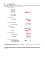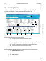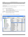
1
ER-0928/1/98
POLARplus Manager User
Guide
File:
Version:
Release Date:
POLARplus Manager UserGuide v3.0_EN.doc
3.0
Mar 31st, 2010
By:
SIDSA
Permissions:
Public
© Copyright SIDSA 2009
All rights reserved
Neither the whole nor any part of the information contained in, or the product described in, this document
may be adapted or reproduced in any material form except with the prior written permission of the copyright
holder.
POLARplus
POLARplus Manager User Guide
V3.0
Disclaimer
The product described in this datasheet is subject to continuous developments and improvements. All
particulars of the product and its use contained in this datasheet are given by SIDSA in good faith. However,
all warranties implied or expressed, including but not limited to implied warranties or merchantability, or
fitness for purpose, are excluded.
This datasheet is intended only to assist the reader in its use of the product. SIDSA shall not be liable for any
loss or damage arising from the use of any information in this datasheet, or any error or omission, or any
incorrect use of the product.
Revision History
Rev.
© Copyright SIDSA, All rights reserved
V1.3
Date
Sep 7th 05
Description
MAM
MAM
Version 5.1
05
MAM
Version 5.4
th
Nov 14 05
MAM
Version 6.0
th
th
V1.4
Sep 29
V1.5
th
V1.6
By:
Oct 21
05
First English version (V5.0)
V1.7
Jan 25 06
MAM
Version 6.3.6
V1.8
March 22th 06
MAM
Version 6.7
V1.9
st
May 31 06
SIDSA Update format
th
MAM
Version 6.13
th
V1.10 Jul 19 06
V2.0
Dic 15 06
MAM
Change of “EtherTV Config Tool” by “POLARplus Manager” and inclusion
of URSUS transcoder
V2.1
June 6th 07
MAM
Included KeyFly CDN devices (Content protection devices)
MAM
Included VegaMux devices
May 20 08
MAM,
JLG
Included DVBS2 EtherTV, Redundancy management, new EtherTV
Bridge configuration
Jul 28th 08
MAM
CSP
New licence policy
SAP configuration, Quality , BER and power parameters
V2.5
Dic 30 th 08
DHC
EtherTV Deluxe and new VegaMUX features (CAS, Automatic PID
remapping and SI tables)
V2.6
May 6 th 09
DHC
Included ORION Receiver/Encapsulator and etherTV-BIN
V2.2
V2.3
V2.4
th
Aug 9 07
th
th
V2.7
Jun 9 09
DHC
Minor changes (with CI decrypted channels depend on CAM, network
interface at PpM installation)
V2.8
Nov 12th 09
VMV
GRC
Added EtherTvMux + OFDM
Added SNMP Management
V2.9
Feb 22nd 10
VMV
Added EtherTvBridge + OFDM
VMV
Added VegaMux with CSA option
V3.0
2
st
Mar 31
10
Public
SIDSA
3.0
POLARplus Manager User Guide
POLARplus
Table of Contents
1
Introduction .................................................................................................................7
2
DVB-IP Gateways .....................................................................................................11
Operation Modes............................................................................................................................... 12
2.1.1
SPTS Mode................................................................................................................................ 12
2.1.2
MPTS Mode ............................................................................................................................... 12
2.2
Searching devices............................................................................................................................. 13
2.3
Management Tasks........................................................................................................................... 16
2.3.1
Configuration of the device parameters..................................................................................... 16
2.3.2
SAP Configuration ..................................................................................................................... 17
2.3.3
Configuration of the LNB parameters (DVBS and DVBS2) ....................................................... 17
2.3.4
Firmware Update ....................................................................................................................... 18
2.3.5
Initialization ................................................................................................................................ 18
2.3.6
Suspend and Resume ............................................................................................................... 19
2.3.7
Management of the slots “Common Interface” (-CI) .................................................................. 19
2.3.8
Events Logging .......................................................................................................................... 19
2.3.9
SNMP Management................................................................................................................... 19
2.4
Configuration ..................................................................................................................................... 24
2.4.1
Streaming Mode......................................................................................................................... 24
2.4.2
Search for the available services/frequencies ........................................................................... 25
2.4.3
Definition of the streaming services........................................................................................... 31
2.4.4
Start and stop a streaming service ............................................................................................ 35
2.4.5
Configuration of DVBS/DVBS2 devices sharing the same antenna.......................................... 35
2.4.6
Configuration of services in devices with “Common Interface” option....................................... 36
3
IP-DVB Gateways .....................................................................................................39
3.1
Searching devices............................................................................................................................. 40
3.2
Management Tasks........................................................................................................................... 41
3.2.1
Configuration of the device parameters..................................................................................... 41
3.2.2
Firmware Update ....................................................................................................................... 42
3.2.3
Initialization ................................................................................................................................ 42
3.2.4
Events Logging .......................................................................................................................... 42
3.3
Configuration ..................................................................................................................................... 43
3.3.1
Configuration of the input service .............................................................................................. 43
3.3.2
Configuration and starting the ASI output.................................................................................. 44
3.3.3
Configuration and starting the COFDM output .......................................................................... 45
4
Transcoders ..............................................................................................................47
4.1
Searching devices............................................................................................................................. 48
4.2
Management Tasks........................................................................................................................... 50
SIDSA
Public
3
© Copyright SIDSA, All rights reserved
2.1
POLARplus
Configuration of the device parameters..................................................................................... 50
4.2.2
Device Licence........................................................................................................................... 51
4.2.3
Firmware Update ....................................................................................................................... 51
4.2.4
Initialization ................................................................................................................................ 51
4.2.5
Events Logging .......................................................................................................................... 51
Configuration ..................................................................................................................................... 52
4.3.1
Streaming Mode......................................................................................................................... 52
4.3.2
Configuration of the input services to transcode........................................................................ 53
4.3.3
Configuration of the transcoding parameters............................................................................. 54
4.3.4
Configuration of the output streaming parameters .................................................................... 54
4.3.5
Start and stop of the transcoded services ................................................................................. 55
5
© Copyright SIDSA, All rights reserved
V3.0
4.2.1
4.3
IP Multiplexers ..........................................................................................................57
5.1
Searching devices............................................................................................................................. 58
5.2
Management Tasks........................................................................................................................... 59
5.2.1
Configuration of the device parameters..................................................................................... 59
5.2.2
Firmware Update ....................................................................................................................... 60
5.2.3
Initialization ................................................................................................................................ 60
5.2.4
Events Logging .......................................................................................................................... 60
5.3
Configuration ..................................................................................................................................... 61
5.3.1
Selection/Configuration of the input services............................................................................. 61
5.3.2
Configuration of the output multiplex (etherTV Mux & vega Mux) ............................................. 62
5.3.3
OFDM Output (etherTv Mux + OFDM) ...................................................................................... 67
5.3.4
Conditional Acess Configuration (vega Mux)............................................................................. 68
6
Distribution................................................................................................................75
6.1
Searching devices............................................................................................................................. 76
6.2
Management Tasks........................................................................................................................... 77
6.2.1
Configuration of the device parameters..................................................................................... 77
6.2.2
Firmware Update ....................................................................................................................... 78
6.2.3
Initialization ................................................................................................................................ 78
6.2.4
Suspend and Resume ............................................................................................................... 78
6.2.5
Events Logging .......................................................................................................................... 78
6.3
Configuration ..................................................................................................................................... 79
6.3.1
Configuration of the encapsulation/encryption operation .......................................................... 79
6.3.2
Configuration of the reception/decryption operation.................................................................. 83
7
4
POLARplus Manager User Guide
Content Protection Devices ......................................................................................86
7.1
Searching devices............................................................................................................................. 87
7.2
Management Tasks........................................................................................................................... 88
7.2.1
Configuration of the device parameters..................................................................................... 88
7.2.2
Firmware Update ....................................................................................................................... 89
Public
SIDSA
3.0
POLARplus Manager User Guide
POLARplus
7.2.3
Initialization ................................................................................................................................ 89
7.2.4
Suspend and Resume ............................................................................................................... 89
7.2.5
Events Logging .......................................................................................................................... 89
7.3
Configuration ..................................................................................................................................... 90
7.3.1
8
Configuration of the encryption/decryption operation ................................................................ 90
Redundancy Management........................................................................................92
8.1
ASI Switch ......................................................................................................................................... 92
8.2
Configuration ..................................................................................................................................... 93
9
CONFIGURATION OF POLARplus Manager ...........................................................97
9.1
General configuration........................................................................................................................ 97
9.2
Configuration of the multicast address generation............................................................................ 97
APPENDIX.........................................................................................................................98
TROUBLESHOOTING.......................................................................................................................... 98
A.1
General.............................................................................................................................................. 98
A.2
DVB-IP Gateways ............................................................................................................................. 99
B
Bitrate Calculation (EtherTV-Bridge) .................................................................................................. 101
SIDSA
Public
5
© Copyright SIDSA, All rights reserved
A
1
Introduction
POLARplus Manager is an application that allows the search, monitoring and configuration of the
POLARplus devices, classified in the following groups:
a) DVB-IP Gateways:
-
etherTV - S
-
etherTV - S2
-
etherTV - T
-
etherTV - C
-
etherTV - ASI
-
etherTV - BIN
b) IP-DVB Gateways:
-
etherTV Bridge
c) Encoders / Transcoders:
-
ursus Transcoder
d) IP Multiplexers:
-
etherTV Mux
-
vega Mux
e) Distribution Devices:
f)
-
Orion Encapsulator
-
Orion Receiver
Content Protection Devices:
-
KeyFly CDN Encrypter
-
KeyFly CDN Decrypter
In order to know in more detail about the fundamentals of these devices, you can see the following
document: “POLARplus Devices.pdf”.
The POLARplus Manager detects automatically the different POLARplus devices and displays them in the
main window (“Device Manager” tab). The main information associated to a POLARplus device is showed in
each line.
© Copyright SIDSA, All rights reserved
POLARplus
POLARplus Manager User Guide
V3.0
The management and configuration of every POLARplus device type is explained in separated chapters for
an easy review.
One of the last chapters in this document is dedicated to explain the redundancy management that
POLARplus Manager performs in group of devices. There will be a primary and a secondary group of
devices (redundancy 1+1), and each group consists of different “connected” devices that builds up a
transport stream in ASI format. POLARplus Manager monitors the right performance of a group, and in case
of fail and depending on the redundancy configuration, will control a ASI switch to select the right ASI output
between the primary and secondary groups. This redundancy management is normally applied to DVB-T/H
headends operation.
The recommended features for the hardware to run the POLARplus Manager are:
Pentium 4 (2 GHz) and 512 MBytes RAM.
Ethernet interface.
200 MBytes free on hard disk.
OS installed: Windows 2K/XP and Linux Redhat/Debian.
IMPORTANT: In order to work with the application it is completely necessary to load once a license provided
by SIDSA (“licence.dat” file located in “SW\POLARplus Manager\Licence” folder on the delivered CD), using
the menu option “File/Load Licence”. In case, the licence is missing or lost, the licence can be asked to your
provider1 sending the prelicence file generated by the software installation (use the menu option “File/Get
Prelicence”). Your provider will reply you with the corresponding licence.
In POLARplus Manager versions before 6.27.12, with the provided licence, you can execute the application
ONLY on the PC or laptop where you has generated the prelicence. From POLARplus Manager version
6.27.12, the licence is unique, and machine independent, for every customer. Also, it is very important to
notice that the provided licence is valid for future SW updates.
The license is generated according to the MAC address of the network interface. If the network interface is
disabled the prelicence file will be wrong and also the licence file wont be correctly loaded.
Moreover, in order to connect to a POLARplus device and configure it, it is completely necessary that the
host, where you have installed the software application, has an IP address belonging to EtherTV subnet. So,
we have to execute Start/ Control Panel/ Network Connection/ Local Area Connection/ Properties/
1
If your provider is SIDSA, send the prelicence file to SIDSA e-mail [email protected] including the
order number associated. SIDSA will reply you with the corresponding licence.
8
Public
SIDSA
3.0
POLARplus Manager User Guide
POLARplus
There is a web page (http://ethertv.sidsa.com), where our customers will be able to download the last
versions of firmware, software and the documentation in relation with. In order to access this page the
customer must be registered, sending an e-mail to [email protected] indicating who is your
provider, in case that there was it. SIDSA will give you a user and password to access this link.
SIDSA
Public
9
© Copyright SIDSA, All rights reserved
Internet Protocol (TCP/IP)/ Properties/ Advanced Options/ P address/ Add, introducing a free IP
address inside POLARplus network.
2
DVB-IP Gateways
POLARplus Manager is an application that allows the search, monitoring and configuration of the
POLARplus devices grouped under the category of DVB-IP Gateways. Inside this category the following
types of devices are found:
-
etherTV - S
(DVBS)
-
etherTV - S2
(DVBS2)
-
etherTV - T
(DVBT)
-
etherTV - C
(DVBC)
-
etherTV - ASI
(DVBA)
-
etherTV - BIN
(DVBA)
The only difference among these types is the input stage of the device: for the three first types, satellite,
terrestrial and cable, there is a module tuning/demodulator, different for each type, that treats the input RF
signal coming from an antenna or modulator; for the ASI type, this input stage does not exist. All the
explanations showed in this chapter apply on all the DVB-IP Gateways devices (referred as “devices” in this
chapter), except the opposite is explicitly said.
There is an additional hardware version for each of these devices (except DVBA device), named “Common
Interface” (CI) that allows to descramble encrypted services using up to two conditional access modules
(CAM) via PCMCIA interface.
For ASI input there are two options ethertTV-ASI and etherTV-BIN. The difference between them is that
etherTV-ASI can obtain the SPTS from a MPTS input (demultiplex) and etheTV-BIN not.
Using POLARplus Manager on these devices, we will be able to carry out some management tasks, as well
as the configuration of the streaming services.
The management tasks are:
Device settings configuration. These settings are the name, network settings, querying
status and TTL.
LNB settings configuration (only in case of DVBS).
Update of the firmware embedded on the device.
Reset of the device, keeping its previous configuration.
Suspend and resume the streaming coming out from the device.
The configuration of a device will consist basically in the election of the operation mode as well as of the
services or programs that the device will serve to the network in format of "transport stream" encapsulated in
IP, utilizing addressing multicast or unicast. These services must be in the same transponder or channel
(except in the case of DVBA that makes no sense), because a device, in a given moment, only can tune in a
single transponder.
On SPTS mode (see following paragraph), using this tool, we will be able to modify the services configured,
changing the direction/port of streaming or adding or removing PIDs. Normally a service will consist of an
set of PIDs: a video PID, one or various audio PIDs and perhaps some data PIDs.
There is a new DVB-IP Gateway Deluxe version with several new features:
Allow an automatic EIT (Event Information Table) Filtering. Service content information is stored into
the EIT. Typically, the electronic program guide or EPG. Using this feature, it is possible to access to
that information per service, and then it could be used to generate automatically a new program
guide.
Increase from 8 to 14 the maximum number of SPTS services (see 2.1.1).
Support BISS decryption (Basic Interoperable Scrambling System) (see 2.4.3.3).
Include a SNMP agent.
POLARplus
2.1
POLARplus Manager User Guide
V3.0
Operation Modes
The device operation mode refers to the filter type that device applies on the input transport stream, and
therefore to the content sent via Ethernet. The device can operate basically in two operation modes, SPTS
mode (Single Program Transport Stream) and MPTS mode (Multiple Program Transport Stream). By default,
the device will work on SPTS mode, and the change of mode is carried out by means of the menu options
"Configuration/Set MPTS Mode" and "Configuration/Set SPTS Mode".
2.1.1
SPTS Mode
In the SPTS mode (Single Program Transport Stream), the device filters part of the information of the input
transport stream. The filtered information is configured in SPTS services (up to eight as maximum or
fourteen for Deluxe version) and encapsulated in IP according to each service streaming configuration.
Normally, the SPTS services present a variable bitrate, and in order to create them, we will start from a list of
available services (see paragraph 2.4.2).
© Copyright SIDSA, All rights reserved
2.1.2
MPTS Mode
In the MPTS mode (Multiple Program Transport Stream), the device filters all the information of the input
transport stream. All this information is configured in a single service MPTS and encapsulated in IP
according to its streaming configuration. Normally, the MPTS service present a constant bitrate, the same as
the input transport stream. In this mode the device acts in a transparent way.
In this case, in order to configure the unique service, we will start from a list of available transponders, except
in case of DVBA device where the election of transponder makes no sense (see paragraph 2.4.2).
12
Public
SIDSA
3.0
POLARplus Manager User Guide
2.2
POLARplus
Searching devices
The search for the DVB-IP Gateways existing in the local network is automatic. The application continuously
shows an updated list of devices in the local network, indicating their status. The DVB-IP Gateways devices
present the text DVBS, DVBS2, DVBT, DVBC or DVBA next to IP address. In case of devices that
incorporate the hardware option “Common Interface” the text include the suffix –CI.
This information is presented in “Device Manager” tab, and can be seen in the following figure.
5
15
17
© Copyright SIDSA, All rights reserved
16
14
8
9
1
10
12
11
2
3
4
13
6
7
The information showed for every device is the following:
(1) Device Status. The meaning of the possible values are:
Green light: the device is streaming out at least one service.
Red light: the device is not streaming out any service.
Crossed antenna: the device is not tuned, either it has not been previously tuned, or is
not receiving RF signal from the antenna/modulator.
Yellow light: temporary status, in which the device is initializing.
No symbol (Board OFF): the device becomes not present (temporal status).
Question mark: the device has been manually connected.
(2) Device Name.
(3) Device IP address.
(4) POLARplus device type that in case of DVB-IP Gateways devices can be the following values:
DVBS or DVBS2: satellite etherTV.
DVBT: terrestrial etherTV.
DVBC: cable etherTV.
DVBA: ASI etherTV.
SIDSA
Public
13
POLARplus
POLARplus Manager User Guide
V3.0
In case of devices that incorporate the hardware option “Common Interface” the type value include the suffix
–CI. Also in DVBS case, the power supply state regarding antenna LNB is presented by means of M
(MASTER) or S (SLAVE). Finally in this column, we can check if the device querying is activated by means
of Q.
(5) Operation Mode: SPTS or MPTS mode. In order to notice this information, the device must be
connected.
(6) Firmware version embedded on device.
(7) Bitrate (Bits/second) coming out from device, including the ethernet, IP, … headers.
(8) List of streaming services configured in device.
The following information is showed for every streaming service (extended information):
(9) The service status. The meaning for the possible values is:
© Copyright SIDSA, All rights reserved
Green tick: the service is configured as running and it is being streamed out.
Yellow tick: the service is configured as running but it is not being streamed out,
because the device is suspended or is not receiving input signal or this signal is not
right.
Red cross: the service is configured as stopped.
(10) The name of the streaming service.
(11) The multicast/unicast address and port number associated with the streaming service.
(12) The streaming mode: SPTS-UDP, SPTS-RTP, MPTS-UDP, MPTS-RTP or MPE (only in SPTS mode).
(13) Bitrate (Bits/second) related with the streaming service. The measure is only about transport stream.
(14) PIDs list associated to the service (extended information). Only video, audio and PCR PIDs are showed.
In case of devices that incorporate the hardware option “Common Interface”, we can see additional
information for the device and associated services (see paragraph 2.3.7):
(15) Status of the two “Common Interface” slots associated to device. This status can be one of the following
ones:
OK : the conditional access module (CAM) is present, initialised and ready to be used.
I? : the conditional access module (CAM) is present, is either initialising or in a state
not ready to be used.
- : the conditional access module is not present.
(16) Slots associated to the service. Every service can be associated to one, two or none slot.
(17) Scrambling status of the incoming service: it can be Scrambled or Free.
We can obtain more information about a given device selecting it with the mouse and using the right button
to execute ‘More Info’ or clicking the icon
. The additional information is in relation with the firmware
version embedded on device, with the tuned transponder, reception quality, BER, power, and/or with CI
slots status (in case of CI hardware option).
14
Public
SIDSA
POLARplus Manager User Guide
POLARplus
© Copyright SIDSA, All rights reserved
3.0
SIDSA
Public
15
POLARplus
2.3
POLARplus Manager User Guide
V3.0
Management Tasks
© Copyright SIDSA, All rights reserved
The management commands are applied to the selected device (highlighted line), but not the “Set
MPTS/SPTS Mode”, “Device Settings” and “LNB Settings” commands that are applied to the device
“connected” (symbol “C”). In the following figure you can see that the selected device, and the device
connected can be different ones. A selected device is done by a simple click on the desired device, and a
device connected can be by three different ways: doing a double click on the device, or selecting the device
(simple click) and either clicking the ‘Connect’ icon (
) or doing the menu option “Manager/Connect”.
2.3.1
Configuration of the device parameters
We can configure the device parameters by clicking the menu option “Configuration/Device Settings” or
clicking the icon
. These parameters are: name (the default value is “Ether-TV”), network settings (IP
address, net mask and gateway address), “querying” status and TTL value. These two last parameters are
inside “Advanced Options”.
The “querying” status parameter is in relation with the multicasting management. Normally, the multicast
traffic generated by these devices is distributed through routers and switches that must support IGMPv2. In
these distribution networks there must be a “querier” that generates ‘IGMP query’ messages. This function is
generally made by a router/switch, but if it is not present you can configure an only one device to perform this
function. The port of the switch or router where this “querying” device is attached to, must support all the
multicasting traffic existing in this switch/router. The “querying” status of the device can be displayed and
modified in “Enable Querier” tick.
The TTL parameter value refers to the value of “Time To Live” field, in the streaming traffic generated from
the device. When an IP packet comes in a router/switch, if its TTL is non zero, the packet will be propagated
with the TTL decremented by 1. So, this value gives us an idea of the scope for the streaming traffic
generated by these devices. The “querying” status and TTL value is configured through the following
window.
16
Public
SIDSA
3.0
2.3.2
POLARplus Manager User Guide
POLARplus
SAP Configuration
© Copyright SIDSA, All rights reserved
In some cases multicast is not enabled in management networks . However it is possible to see status in
Polarplus Manager configuring the announce protocol (SAP) on Unicast address:
The main limitation of this mode is that only one manager is possible.
2.3.3
Configuration of the LNB parameters (DVBS and DVBS2)
This configuration only applies to DVBS/DVBS2 devices and is in relation with the power supply features
that the device provides to the antenna LNB. These features determine the transponders that the device can
tune: they establish the possible band and polarization for the tuned transponders.
These parameters with their default values are presented in the following figure.
SIDSA
Public
17
© Copyright SIDSA, All rights reserved
POLARplus
POLARplus Manager User Guide
V3.0
Firstly, the device can be configured as MASTER supplying LNB (DVBS/S2 M), or as SLAVE not supplying
LNB (DVBS/S2 S). The antenna LNB has to be supplied, so if there are some devices plugged to the same
LNB, only one has to be configured as MASTER and supply the LNB. The rest of the boards has to be
configured as SLAVE associated with the MASTER (we select the MASTER IP address in the “Dish Group”
box).
In case of MASTER device, we have to select the LNB type that we are using. For an universal LNB, we
present the following parameters and their default values:
LNB Low Frequency (MHz) = 9,750
(local oscillator for lower band)
LNB High Frequency (MHz) = 10,600
(local oscillator for higher band)
LNB Switch Frequency (MHz) = 11,600
If we are using a different LNB type, the important data to know about it is the number of the local oscillators
(single or double band), and the value of its local oscillators.
The tuner of the device presents a frequency range 0.95-2.15 GHz and using an universal LNB, the Ku band
(10.7 – 12.75 GHz) is completely covered:
Low Band: 10.70 - 11.9 GHz
(9.75+0.95) - (9.75+2.15)
High Band: 11.55 - 12.75 GHz
(10.6+0.95) - (10.6+2.15)
The parameter “LNB Switch Frequency” fixes the limit between using the lower or higher local oscillator of
the LNB.
Finally, when the device is MASTER, we can force the characteristics of the power supply to LNB (level and
tone). We recommend you to keep these parameters in automatic: the level and tone values are set
according the polarization and sub-band of the transponder you are tuning at every moment.
2.3.4
Firmware Update
The POLARplus Manager presents the option to update the firmware embedded in the selected device or in
all devices existing in the local segment, by clicking the menu options “Manager/Upload” and
“Manager/Upload ALL” (
and
respectively in the icon bar). In both cases, a dialog window comes up,
inviting you to introduce the binary file to upload. Once the firmware update is finished, the device will be
restarted.
2.3.5
Initialization
The menu option “Manager/Reset” allows initializing the selected device, leaving intact the current
configuration including the streaming services previously configured.
18
Public
SIDSA
3.0
2.3.6
POLARplus Manager User Guide
POLARplus
Suspend and Resume
The menu options “Manager/Suspend”, “Manager/Resume”, “Manager/Suspend ALL”, and
“Manager/Resume ALL”, allow suspending or resuming the selected device or all existing devices in the local
network (
and
respectively in the icon bar).
The device suspension implies that the device stops the streaming of all its running services. As a
consequence of suspension, the traffic light of the device will change to red and the green ticks of the
running services to yellow. In the same way, in “Streaming Services” tab, the green color of the running
services will change to yellow.
When we resume the device, the previously suspended services will return to be streamed out. These
services will return to green.
A device initialization caused by either a hardware reset or a command from the application (Upload and
Reset), implies a resume of the all suspended services.
2.3.7
Management of the slots “Common Interface” (-CI)
2.3.8
Events Logging
There are two buttons (arrows) in the right border of the main window in order to maximize or minimize the
logging window. This window contains a registration of all the events related to any change of the status in
the devices or its associated services. Besides, it includes a registration of the commands executed from
menu option “Manager”.
2.3.9
SNMP Management
The new DVB-IP Gateway Deluxe version include a SNMP agent, that allow these boards to be managed
using a SNMP Manager, by including them as managed elements in a SNMP Network. The Management
Information Base (MIB) is provided in the file “ethertv-mib.mib”, in the CD included in the order. If you need it
and cannot find it, contact [email protected].
With this MIB and an SNMP manager you have the possibility to monitor the DVB-IP Deluxe Gateways
status (by SNMP traps). There are various SNMP management tools available to issue SNMP based
commands to the appliance (Software not supplied by SIDSA).
SIDSA proposes to use the MIB Browser by iReasoning to monitor DVB-IP Deluxe Gateways. iReasoning
offers a free version of the MIB Browser under www.ireasoning.com, which is useful to read the actual status
or setting up the variables. See below for further information.
SNMP uses the following standard ports: Port 161 and port 162
Port 161 is used by the SNMP manager and the agent to send the Requests and their Responses.
Port 162 is used by the SNMP agent to send TRAPs to the SNMP manager.
Make sure that these ports are not blocked in your network.
The following operations are possible with SNMP
GET
Read out the management information
GETNEXT
Read out the management information iteratively, which is useful if you want to read the
information down the MIB tree step by step
GETBULK
Read out the management information of the complete list/tree
SET
Change/set the management information
TRAP
Start the Trap receiver in your SNMP manager to get alerts of the managed system.
SIDSA
Public
19
© Copyright SIDSA, All rights reserved
When a device with the option hardware CI is connected, there is a new menu in the application: "CI
Manager". By means of this new menu, we will be able to obtain information about conditional access
modules (CAM) inserted in the slots, and carry out operations on them, as reset and power off. Also, we will
be able to enter the proprietary menus of the CAM inserted.
POLARplus
POLARplus Manager User Guide
V3.0
SNMP Variables:
etherTVTrapSink: this variable defines the IP address used to send traps generated by the agent.
etherTVglobalTrapEnable: it allows enabling or disabling all the traps issued by the agent. (‘1’ =
enabled, ‘2’ = disabled). This is the first variable to set, and it should have the IP address of the PC
where the SNMP Manager (Trap Receiver) is installed, or the PC where the MIB Browser is running.
etherTVtrapEnableColdstart: it allows enabling or disabling the ColdStart trap generation.
etherTVtrapEnableHeartbeat: it allows enabling or disabling the HeartBeat trap generation
according to the etherTVHeartbeatFreq value. (‘1’ = enabled, ‘2’ = disabled).
etherTVtrapEnableSignalLoss: it allows enabling or disabling the SignalLoss trap generation
according to the etherTVTrapSignalLossTHD value. (‘1’ = enabled, ‘2’ = disabled).
etherTVtrapEnableLowBitRate: it allows enabling or disabling the LowBitRate trap generation
according to the etherTVtrapLowBitRateTHD value. (‘1’ = enabled, ‘2’ = disabled).
etherTVtrapEnableBoardStatusChange: it allows enabling or disabling the BoardStatusChange
trap generation. (‘1’ = enabled, ‘2’ = disabled).
© Copyright SIDSA, All rights reserved
etherTVtrapHeartbeatFreq: it determines the repetition period of the HeartBeat trap in seconds
when etherTVtrapEnableHeartBeat has the ‘enabled’ value.
etherTVtrapRepeatFreq: it determines the repetition period of all the traps, except the HeartBeat
trap, when etherTVtrapRepeatEnable has the ‘enabled’ value.
etherTVtrapSignalLossTHD: it is the signal loss threshold value. If RF signal value falls below this
value, a SignalLoss trap is issued if it is enabled.
etherTVtrapLowBitRateTHD: it is the low bit rate threshold value. If streaming bitrate falls below
this value, a LowBitRate trap is issued if it is enabled.
etherTVHeartBeat: it notifies that the EtherTV device is alive.
etherTVSignalLoss: it is issued when the RF signal is low, according to the threshold value set in
the etherTVtrapSignalLossTHD variable.
etherTVSignalOK: it is issued when the RF signal gets back a value greater than the
etherTVtrapSignalLossTHD variable.
etherTVLowBitrate: it is issued when the bitrate of a streaming service is low, according to the
threshold value set in the etherTVtrapLowBitRateTHD variable.
etherTVBitrateOK: it is issued when the bitrate of a streaming service gets back to a value greater
than the etherTVtrapLowBitRateTHD variable.
etherTVBoardStatusChange: it is issued when a board changes its status (tuned, not-tuned, wait,
off, ...).
ColdStart: it is issued when a device is reinitializing itself and its configuration may have been
altered.
Below you can find a short overview of the MIB Browser by iReasoning, to show the basic points of using
SNMP.
1) Install the MIB Browser and launch it.
2)Load the MIB file.
Click on File > Load MIBs and choose the folder with the MIB file “ethertv-mib.mib”.
20
Public
SIDSA
3.0
POLARplus Manager User Guide
POLARplus
3) Set up the agent
© Copyright SIDSA, All rights reserved
Click on Tools > Options and choose “Agents”
Click on “Add” and the following window will open to add an SNMP device
Adress: Type in the IP address of the SNMP agent, in this case the DVB-IP Deluxe Gateway.
Port: The default port used is 161, change it if you are using another one in your SNMP Network.
Read and Write Community: for SIDSA agent, public is used for both Read and Write Community.
Press Ok to save the Agent properties.
SIDSA
Public
21
POLARplus
POLARplus Manager User Guide
V3.0
Add more agents if necessary (there should be so many agents as DVB-Ip Deluxe Gateways in the SNMP
Network). When finished, press Ok.
On MIB Browser main window, choose the ETHER TV-MIB and right click on it. Click on “Expand subtree” to
see all the variables.
Select the agent of the DVB-IP Deluxe Gateway in the field Address.
The common operations of the MIB Browser are:
Get
Read out the management information
Get Next
Read out the management information iteratively, which is useful if you want to read the
information down the MIB tree step by step
Get Subtree
Read out the management information of the selected subtree
Walk (Getbulk) Read out the management information of the complete list/tree
© Copyright SIDSA, All rights reserved
Set
Change/set the management information
You can use the operation “Walk” to read all the variables from the selected agent.
22
Public
SIDSA
3.0
POLARplus Manager User Guide
POLARplus
© Copyright SIDSA, All rights reserved
Then we can select, e.g. the variable (aka OID) “etherTVTrapSink” and execute the operation Set to set the
correct value.
SIDSA
Public
23
POLARplus
2.4
POLARplus Manager User Guide
V3.0
Configuration
Firstly, we have to check that device is operating on the desired mode (see paragraph 2.1). In order to
change the operation mode, we should execute the corresponding menu option “Configuration/Set xxx
Mode”. When we change the operation mode, the previous service configuration is deleted.
Once the operation mode is selected, the configuration of a DVB-IP Gateway device will consist in the
following steps:
Search for the available services/transponders that the device receives.
Definition of the streaming services.
Start and stop the streaming services.
© Copyright SIDSA, All rights reserved
In order to configure a device, firstly we must connect to it. We remind you that a board connected is set up
by three different ways: doing a double click on the device, or selecting the device (simple click) and either
clicking the ‘Connect’ icon or doing the menu option “Manager/Connect”.
We can configure a device which is not listed (the application couldn’t detect it), if we know that it is available
(check by a ping to the IP address using a command console) and we know its IP address. We have to click
in the menu option “Manager/Manual connection”. If the application achieves to connect the device, this will
be added to the list with an unknown state (?).
Whatever operation that implies a deletion of the configured services in the device, as is a change in the
operation mode or in the tuning/demodulating parameters, the application warns and invites us to save the
previous configuration in a file for its subsequent recovery (see 2.4.3).
Before analyzing the search and configuration of services, we are going to see a summary of the different
options in the streaming mode. We analyze further the cautions to follow in order to configure DVBS devices
in case they are sharing LNB. Finally, we will see the features in the configuration of devices that include the
hardware option "Common Interface".
2.4.1
Streaming Mode
The streaming mode of a service refers to the content and encapsulation protocol over what is sent via
ethernet related to the service, and it is depending on the device operation mode:
⇒ In SPTS mode, there are two possibilities:
24
Public
SIDSA
3.0
POLARplus Manager User Guide
POLARplus
Transport Stream: The transport stream related to the configured PIDs for the service
is encapsulated in IP using UDP or RTP protocols and unicast or multicast addressing.
In this case, the device generates and sends the service information tables (PAT, PMT
y SDT).
MultiProtocol IP (MPE): The device sends via ethernet the IP packets included in
special sections MPEG (encapsulated in TS) that are transmitted in DVB. Using this
streaming mode, the device can filter the IP packets corresponding to the configured
multicast IP address, inside the MPEG section related to the configured PID (only a
PID per service). If “Uses IP to MAC mapping” tick is marked, the device will filter all IP
packets corresponding to the first ‘x’ bytes (less meaning) of the MAC address (using
multicast to MAC mapping), associated to the configured PID. If this tick is not marked,
the device will extract all IP packets corresponding to the configured PID.
⇒ In MPTS mode, the filtered information can be encapsulated in IP using UDP or RTP protocols and
unicast or multicast addressing. In this case, the device doesn’t generate any service information table.
2.4.2
Search for the available services/frequencies
Independently the operation mode, we always refer to a services search, although depending on the
operation mode, the “Database" tab will show the list of available services (SPTS mode), or a list of available
transponders (MPTS mode).
The search in DVBS, DVBS2, DVBT and DVBC devices can be done in two different ways: manual (
) or
automatic (
). For DVBT devices, the available transponders depend on the zone where we are; for
DVBC devices the available services depend on the cable operator, and for DVBS devices depend on the
satellite where the antenna is oriented. The data of all available transponders for every satellite are updated
in the web page www.lyngsat.com. We are interested in the satellites that broadcast DVB services.
Obviously, we can only tune the transponders associated to the satellite that our antenna is pointing to.
Whatever search in a transcoder or frequency different to the currently tuned, will cause a deletion of the
configured services, in case they were. The application will warn and invite us to save this configuration
before being deleted.
IMPORTANT: The search in DVBA devices is only automatic and is simpler than in the other types of
devices because it doesn’t have any parameter. This search doesn’t imply any modification in the currently
configured services.
Any kind of search will result in a list of available services/transponders (see paragraph 2.4.2.3).
2.4.2.1 Manual search in DVBS, DVBS2, DVBT and DVBC devices
The manual search allows the search of services included in a given transponder or channel. In order to
search we have to execute the menu option “Search/Manual Search”, having selected the “Database” tab. It
comes up one of the following windows depending on the device type is being used:
DVBS
SIDSA
DVBT
Public
25
© Copyright SIDSA, All rights reserved
This step is not necessary if the services or transponders to configure are already in the “Database” in the
SPTS or MPTS mode respectively, or they are previously saved into a configuration file. If they are not, we
have to make a previous search.
POLARplus
POLARplus Manager User Guide
DVBS2
V3.0
DVBC
Through these windows, we introduce the parameters related to the tune/demodulating of the desired
transponder:
DVBS: frequency, symbol rate, polarization and FEC.
© Copyright SIDSA, All rights reserved
DVBS2: frequency, symbol rate, polarization and FEC and DBVS or DVBS2
modulation selection.
DVBT: frequency or channel, bandwidth, hierarchy and zone.
DVBC: frequency, symbol rate and constellation.
The rest of parameters, satellite for DVBS/DVBS2, subzone for DVBT and cable operator for DVBC, are
simply used to classify and store properly the search results (services/frequencies). We can add, modify or
delete these elements using the corresponding “Services” menu option.
Once the search parameters are introduced and we click the “Scan” button, the application starts to search
for the available services in the selected frequency.
If we want to search for a given service, we also have to introduce its name in the “Filter by Channel Name”
box.
If we tick “All programs in the same Network” for transponder case, the application will search for in all
transponders associated to the same network. This action is equivalent to do an automatic search in a given
network (see paragraph 2.4.2.2).
During the services search, the application shows up the process state by the following window:
If we click on “Abort” button, the search is cancelled and the services/frequencies found at this moment, are
shown up. Once the search is finished, the resulting services/frequencies are highlighted in the “Database”.
26
Public
SIDSA
POLARplus Manager User Guide
POLARplus
2.4.2.2 Automatic search in DVBS, DVBS2, DVBT and DVBC devices
The automatic search allows the search of all services included in the input signal. In order to search we
have to execute the menu option “Search/Automatic Search”, having selected the “Database” tab. As in the
manual search, to execute the command implies the deletion of a previous services configuration in the
device, and the application will warn you. Depending on the device type:
a ) Automatic search in DVBS, DVBS2 and DVBC devices
The application shows the following window that invites you to introduce the satellite or the cable operator in
which the search results are going to be saved.
DVBS/DVBS2
DVBC
Selecting a satellite/cable operator and clicking the “Scan” button, the application will start the search for
every service included in all frequencies related to the satellite/operator, and in all frequencies included in
the network information (NIT) of the previous ones. The results are presented in the same way as in the
manual search case.
In order to see the frequencies related to a satellite/operator, we make a double click on the
satellite/operator, or either “Admin. Satellites/Modify Satellite” or “Admin. Cable Operators/Modify Cable
Operator” menu options are executed.
SIDSA
Public
27
© Copyright SIDSA, All rights reserved
3.0
POLARplus
POLARplus Manager User Guide
DVBS/DVBS2
V3.0
DVBC
© Copyright SIDSA, All rights reserved
This list includes all previously scanned frequencies for the satellite/operator. In case of DVBS and DVBS2, if
there wasn’t any previous search for a satellite, the frequencies list is empty, but we can load a default
frequency list by clicking “Load Default Information” button. As many transponders we have in the list, the
automatic search result will be more. In this window we can edit new or existing transponders, and add or
delete it in the list associated to the satellite.
In the tab “Network Search” of “Automatic Search”, we find a list of all networks for the selected
satellite/operator, which were previously found.
DVBS/DVBS2
Selecting a network, and clicking “Scan”, the application starts the search for every services belonging to this
network. If we tick the option “All Available Networks”, the search will be done for all available networks for
the satellite/operator. This action is equivalent to do an automatic search for the satellite/operator.
If you want to search for a satellite/operator that is not in the list, you can add it executing the menu option
“Admin. xxx/Add xxx”. In the following window you introduce the name and the set of frequencies for an initial
automatic search.
DVBS/DVBS2
28
DVBC
Public
SIDSA
3.0
POLARplus Manager User Guide
POLARplus
In order to modify the data of a existing satellite/operator, you can select this one from the list, and click on
the menu option “Admin. xxx/Modify xxx”. If you want to delete all data about a satellite/operator, you have to
select this one and click on “Admin. xxx/Delete xxx”.
Unlike the satellites/operators list, the only modification permitted on the network list, is the deletion.
Therefore, if we want to delete the data of a network associated to a satellite/operator, we have to select the
network and click on the menu option “Admin. Networks/Delete Network”.
b ) Automatic search in DVBT devices
After clicking OK, the application will search for in all available channels in the selected region. In this case,
all services that are found, are grouped under a network that is named as the selected subzone. The results
are presented in the same way as other searches.
2.4.2.3 Service/Frequency list
After any kind of search in any device, all services that have been found will be stored in a database of
services and frequencies. There will be four different databases corresponding to each device type (in case
of DVBA, the database will be temporal). The services (SPTS mode) and transponders (MPTS mode) in the
database are displayed on “Database” tab.
In the case of DVBT devices, the available services/frequencies are grouped in world zones; meanwhile, in
the case of DVBS/S2 and DVBC devices, the available services/ frequencies are grouped in satellites or
cable operators and networks. In the case of DVBA devices, the available services are only grouped by IP
address of the device where they were found.
In order to see the services/ frequencies related to a given zone/satellite/operator/IP and subzone/network,
you have to select these parameters from the drop-down lists placed at the top of the window.
DVBS/DVBS2
The following data are displayed for each service:
SIDSA
Public
29
© Copyright SIDSA, All rights reserved
The application shows a window to introduce the world region where we are, the subzone where the results
will be saved, the channel bandwidth and the hierarchy that are used for the target services. In the most of
the countries the channel bandwidth is 8 MHz, but in other countries can be different (6 or 7 MHz).
POLARplus
POLARplus Manager User Guide
V3.0
Name: Name of the service.
Service Type: Type of the service. It can be:
- Digital Television Service.
- Digital Radio Sound Service.
- Data Broadcast Service.
- MPEG2 HD Digital Television Service.
- Unknown Service Type.
TstreamId: Transponder identifier associated to the service.
© Copyright SIDSA, All rights reserved
NetworkName: Name of the network related to the service.
Apart from this data, we can get more information from the selected service through the menu option
“View/Advance View” (
). To click on this option, a new frame appears on the right side of the window,
with information about the service: network, frequency, assigned PIDs, conditional access, and other
information as name, language, etc… This advance view is kept in the “Streaming Services” tab on the
service selected.
DVBS/DVBS2
In order to manage easier the services list, the application allows applying a filter to one of the previously
mentioned four fields. In this way, we can display a subset of services that complies the filter. To define this
filter, click on the menu option “View/Filter”. Once this is done, the following window comes up:
In this window, we can select the field to filter and the desired value. To apply the filter, we click on “Apply
Filter” button. If we want to remove the filter, we click on the menu option “View/Filter”, and click on “Remove
Filter” button.
30
Public
SIDSA
3.0
POLARplus Manager User Guide
POLARplus
The service/frequency list stored in the database is enlarged with the results from consecutive searches. We
can delete services from the database in three different ways from the menu “Services”:
Select a satellite or cable operator name (only for DVBS, DVBS2 and DVBC) from the
drop-down list and click on the menu option “Delete xxx”. This option will erase all
services/frequencies about the selected satellite/operator.
Select a network name (for all devices but DVBA) from the drop-down list and click on
the menu option “Delete Network”. This option will erase all services/frequencies about
the selected network.
Select one or some services from the list and click on the menu option “Delete
Service/s”. This option will erase only the selected services.
All data about the services/transponders that have been found are saved in the file “SystemData.xml” located
in the application root path. We can export these data to another file ‘xml’ with the menu option “File/Export
Database” (
). Also, the application presents the option to work with other services lists, importing these
data from a file with extension ‘xml’ (it is supposed to be exported previously). In order to do this, you click on
the menu option “File/Import Database” and select the file that contains the data (
).
Definition of the streaming services
In SPTS mode, there are three different ways to define a new streaming service:
From a service in the database.
From a streaming service just defined.
From information in database with no previous service reference.
Meanwhile, in MPTS mode only is possible to define the streaming service from a transponder existing in
database (in case of DVBA, it is not necessary any previous information to define the MPTS service).
The streaming services defined for a given device are listed in “Streaming Services” tab. The list showed in
this tab is associated to the device to configure.
Independently the operation mode, the streaming services configuration can be restored from a file that has
been previously saved. The menu options “Stm. Services/Load Streaming Configuration” and “Stm.
Services/Save Streaming Configuration” are used to do this.
An example of streaming services list is the following:
⇒ The following data are presented for each streaming SPTS service:
Name: Name of the streaming service.
Status: Status of the streaming service. The possible values are:
•
SIDSA
No Config: the streaming service has just been added to the list and it has not
been defined yet in the device.
Public
31
© Copyright SIDSA, All rights reserved
2.4.3
POLARplus
POLARplus Manager User Guide
V3.0
•
Running: the streaming service has been defined as “running”; if it is on green,
the device is streaming it out, but if it is on yellow the service is either
suspended or the device is not receiving signal from.
•
Stop: the streaming service has been defined as “stopped”; the device is not
streaming it out.
TstreamId: Identifier of the transponder which the service belongs to.
Components: Enumeration of the PIDs that makes up the streaming service.
IPTarget: Multicast/unicast address related to the streaming service. If this value is not
introduced before starting the service, the application set automatically a default value
for it. Afterwards, you can modify this parameter if you wish.
PortTarget: Target port related to the streaming service.
© Copyright SIDSA, All rights reserved
⇒ Meanwhile, the information presented for a MPTS service is the same except Components and
TstreamId, being substituted by the frequency information.
The parameters associated to a streaming service can be modified, whenever this service is not running,
making a double click on it, or executing the “Stm Services/Modify Streaming Service” menu option. A more
detailed explanation of the edition of these parameters can be located in the paragraph 2.4.3.3.
2.4.3.1 Definition of a streaming service from an existing service/transponder in database
This way to define a streaming service is the more common. From “Database” tab, we select the service or
services that we want to define as streaming services. These services pass to the “Streaming Services”
clicking on the icon
, or on the menu option “Services/Create Streaming Service(s)”. In MPTS mode we
can only add a service, but in SPTS mode it is possible to add up to eight services in the same transponder.
In SPTS mode, by default, the application adds up the services only with video and audio PIDs (plus PCR
PID); but if the user wants to create the services with all the PIDs that make up them, from “Database” tab,
he has to select the menu option “View/Advanced View”, and with the service(s) selected, pulse the menu
option “Services/Create Streaming Service(s) with ALL PIDs”. You have to be careful with this alternative
because you can add up PIDs that are not necessary for our goal, and run out the device hardware
resources; so, if you want to add up any PID different from video or audio, we recommend you add up these
PIDs modifying the service created with only video and audio PIDs (menu option “Stm Services/Modify
Streaming Service”).
In order to add up the information of some descriptors included in the original PMT associated to the service,
we should activate “Enable PMT Descriptors” tick and select those we want to introduce. When a descriptor
is added, the possible component or components associated are also added; this is the case of the teletext
descriptor: if we add the teletext descriptor (tag 0x56), the component or PID that contains the teletext data is
added up.
A streaming service defined like this, initially presents a “No Config” state and all video and audio PIDs that
make up the original service. The generated IP Target belongs to the multicast address range and follow
the rule configured and explained in the paragraph 9.2. The default value for Port Target is 20000. The
default Streaming Mode is SPTS-UDP o MPTS-UDP depending on the operation mode.
32
Public
SIDSA
3.0
POLARplus Manager User Guide
POLARplus
2.4.3.2 Definition of a streaming service from an existing streaming service (SPTS)
In order to define a streaming service from an existing one, we have to select this one and copy it, clicking on
the menu option “Stm Services/Copy Streaming Service”.
Once it is copied, the new service will be in the list as a copy of the former but with the PIDs field
unassigned. Before the new service can be started, it is necessary to edit the PIDs field. The definition of the
rest of the parameters for the new service will follow the rules seen in previous paragraph.
2.4.3.3 Definition of a streaming service with no previous service reference (SPTS)
“General Information”: this tab includes the basic parameters of the streaming service, as name, IP
addressing and streaming mode:
“Service Name”: mandatory field that means the name of the streaming service.
“IP Target”: mandatory field that indicates the target IP address. This address can be
configured as multicast or unicast. In case of multicast address, this will be in the
range 224.0.0.0 – 239.255.255.255. We recommend see the documents RFC 3171
and 2365 for a proper multicast address choice. In this case, the traffic generated from
the device for this service is multicast and would be received by all clients joined to this
multicast group. See IGMP protocol.
In case of unicast address, the traffic generated from device will reach only the given
address.
“IP version”: at this moment, the device only supports version 4. In a future, it will also
support version 6.
“Port Target”: mandatory field that means the target port related to the streaming
service. This value can be in the range 1026 – 65535 and has to be multiple of 2.
“Port Source”: mandatory field that means the source port related to the streaming
service. This value can be in the range 1026 – 65535 and has to be multiple of 2.
“Service Type”: optional field where we can introduce a short description of the
streaming service.
“Provider”: optional field where we can introduce the provider name of the streaming
service.
“Streaming Mode”: mandatory field that indicates the content type and protocol used
in the service streaming: SPTS-UDP, SPTS-RTP and IP-Multiprotocol (MPE) for
SIDSA
Public
33
© Copyright SIDSA, All rights reserved
In order to define a new service, we have to click on the menu option “Stm Services/Add New Streaming
Service” ( ). The following window will pops up with different tabs “General Information”, “PIDs Information”
and “Descriptors Information”:
POLARplus
POLARplus Manager User Guide
V3.0
devices in SPTS mode, and MPTS-UDP, MPTS-RTP for devices in MPTS mode (see
paragraph 2.4.1).
It exists an additional field for Deluxe version to BISS (Basic Interoperable Scrambling System) decryption,
that could be enable or disable. In case of BISS enable, a Control Word has to be introduced:
© Copyright SIDSA, All rights reserved
The information in “PIDs Information” and “Descriptors Information” are only applied for devices in SPTS
mode:
“PIDs Information”: mandatory field that enumerates the list of PIDs to be filtered and streamed out. We can
only use the PIDs previously found to fill in this field. For DVBS, DVBT and DVBC devices, these PIDs are
associated to frequencies, these are associated to networks and finally these are to satellites for DVBS,
subzones and zones for DVBT and cable operators for DVBC. We notice that the list of PIDs only can be
made up by PIDs belonging to an unique frequency, and it is not possible more than a video PID. The list of
available PIDs can show either VIDEO/AUDIO PIDs or all PIDs that are found in the PMT of all services in
the selected transponder. In case that all PIDs are shown, using the “Ghost Component Manager” button, we
can add PIDs not present in the PMTs in order to select them.
“Descriptors Information”: When we create a service, the device generates the following service
information tables: PAT, PMT and SDT which refers to the new service created and its components. By
default, the PMT doesn’t contain any descriptor, and if we want to introduce any type of it, we must tick
“Enable PMT Descriptors”, and select whatever type we want. Be careful, because the PMT present a length
limit, so we can not introduce all we want. If the descriptor has information associated in other components,
these components will be automatically added up, when the descriptor is selected. The addition of some
descriptors in PMT generation is completely necessary, so any player can recognize some information
added to the TS, as teletext or AC3 audio information.
34
Public
SIDSA
3.0
POLARplus Manager User Guide
POLARplus
In the same way we have defined all these parameters for a new streaming service, we can edit or modify it,
with the only condition that the service has not be running. To proceed with the service edition, we have to
select it and click double on the field to edit, or click on the menu option “Stm Services/Modify Streaming
Service”.
Finally, we have to notice that we can delete streaming services from the list, selecting it and clicking on
either the menu option “Stm Services/Delete Streaming Service/s”, or the icon
.
2.4.4
Start and stop a streaming service
In order to start a streaming service is necessary to select it and click on either the icon
or the menu
option “Stm Services/Start Streaming Service”. If the communication between application and device has
been successful and the streaming service has been started, its status will change to “Running" in green
color.
In order to stop a streaming service is necessary to select it and click on either the icon
or the menu
option “Stm Services/Stop Streaming Service”. If the streaming service has been stopped, its status will
change to “Stop" in red color.
2.4.5
Configuration of DVBS/DVBS2 devices sharing the same antenna
This subject only applies to DVBS/DVBS2 devices that are sharing the same LNB, that is, the same cable
from the antenna: LNB has to be supplied only by a device (see paragraph 2.3.3). The device that supplies
LNB is configured as MASTER, whereas the rest of the devices are configured as SLAVE. In the boards list
(Device Manager tab), firstly is the MASTER device followed by the SLAVE devices associated. If there is a
SLAVE device associated to a MASTER device not present in the list, this will appear with the status
SLAVE??? in red color.
We RECOMMEND to configure the group of devices MASTER – SLAVEs, being connected simultaneously
to the network, and configure firstly the MASTER device, and afterwards the SLAVE ones.
The configuration of the MASTER is made normally following the steps previously explained. Once the
MASTER device is configured, we proceed with the rest of the devices configured as SLAVE, taking into
account that it is only possible to do automatic/manual searches or configure services in transponders at the
same band and with the same polarization that the transponder tuned in the MASTER device.
For a better explanation, we are going to analyze a practical example, putting special emphasis on one of
the configuration parameters of the LNB (LNB Switch): We have three devices with no previous
configuration and sharing an universal LNB of an antenna pointing to ASTRA satellite. We want to configure
the devices with streaming services in the following transponders:
SIDSA
Public
35
© Copyright SIDSA, All rights reserved
Once we have filled out the data, it is necessary to click on “Save” button to add the service to the
“Streaming Services” list.
POLARplus
POLARplus Manager User Guide
Freq: 11.568 MHz Pol: V
( RAI Uno, ARTE )
Freq: 11.597 MHz Pol: V
( BBC, CNBC )
Freq: 11.686 MHz Pol: V
( TVC, TV Galicia )
V3.0
In an universal LNB, we present the following parameters and their default values:
LNB Low Frequency (MHz) = 9,750
(local oscillator for lower band)
LNB High Frequency (MHz) = 10,600
(local oscillator for higher band)
LNB Switch Frequency (MHz) = 11,600
The tuner of the device presents a frequency range 0.95-2.15 GHz and using an universal LNB, the Ku band
(10.7 – 12.75 GHz) is completely covered:
Lower band: 10.70 to 11.9 GHz (9.75+0.95) to (9.75+2.15)
Higher band: 11.55 to 12.75 GHz (10.6+0.95) to (10.6+2.15)
© Copyright SIDSA, All rights reserved
The parameter “LNB Switch Frequency” fixes the limit between using the lower or higher local oscillator of
the LNB.
As we have said before, the transponders tuned by different devices that share the same LNB, must be at
the same band and present the same polarization. The three transponders present the same polarization,
but according to the LNB parameters, the first two are at the LOW band and the third at the HIGH one. In
order to get along the three transponders, we can take advantage of the certain flexibility that LNB Switch
parameter presents: it can be slightly modified to 11.700 MHz in a board, so the three transponders are now
at the same band (LOW). The configuration would be:
-
EtherTV 1: RAI Uno, ARTE.
EtherTV 2: BBC, CNBC.
EtherTV 3: TVC, TV Galicia.
MASTER
SLAVE
SLAVE y LNB Switch 11.700 MHz
The flexibility for the “LNB Switch” parameter depends on the value of the LNB local oscillators. For an
universal LNB, the LNB Switch Frequency will be in the range 11.55 - 11.9 GHz.
2.4.6
Configuration of services in devices with “Common Interface” option
The configuration of streaming services in a device that includes the hardware option CI is exactly in the
same way that in a device with no CI option, but in case we want to descramble services using conditional
access modules (CAM), it will be necessary to do an additional configuration step: “Slot Association”.
In order to descramble a service using one or two conditional access modules, besides inserting the modules
into available CIs, we have to associate the service with the corresponding slot/s. In this way, if a service
presents a “Scrambled” status, and is associated to at least one slot, where a suitable CAM and smartcard
are inserted, the service is descrambled and ready to be streamed out.
36
Public
SIDSA
3.0
POLARplus Manager User Guide
POLARplus
NOTE 1: Every time you modify the configuration of services associated to slots, it is recommended to
RESET the EtherTV board to assure a correct performance.
© Copyright SIDSA, All rights reserved
NOTE 2: The number of decrypted services depends on the CAM.
SIDSA
Public
37
3
IP-DVB Gateways
POLARplus Manager is an application that allows the search, monitoring and configuration of the
POLARplus devices grouped under the category of IP-DVB Gateways. Inside this category the following
type of devices are found:
-
etherTV BRIDGE
All the explanations showed in this chapter apply on this type of devices, and from now to chapter end they
will be referred as “devices”.
Using POLARplus Manager on these devices, we will be able to carry out some management tasks, as well
as the configuration of the ASI stream in the output.
The management tasks are:
Device settings configuration. These settings are the name, network settings, querying
status and TTL.
Update of the firmware embedded on the device.
Reset of the device, keeping its previous configuration.
The configuration of a device will consist basically in the configuration of the input MPTS service (or two
input services in case of the redundancy management is enabled). The outgoing transport stream coincides
exactly with the input transport stream, so the device doesn’t process the input transport stream and doesn’t
generate any SI tables. It is very important that the input transport stream presents a constant bitrate, and
this value will be the most approximate to the configured value.
NOTE: Inside the IP-DVB Gateways, we can consider the etherTV Mux device because presents IP input
and ASI output, but we will explain it inside IP Multiplexers section.
POLARplus
3.1
POLARplus Manager User Guide
V3.0
Searching devices
The search for the IP-DVB Gateways existing in the local network is automatic. The application continuously
shows an updated list of devices in the local network, indicating their status. The IP-DVB Gateways present
the text BRIDGE or BRIDGE-COFDM next to IP address.
© Copyright SIDSA, All rights reserved
This information is presented in “Device Manager” tab, and can be seen in the following figure.
1
2
3
4
5
6
The information showed for every device is the following:
(1) Device Status. The meaning of the possible values is:
Green light: the device is transmitting.
Red light: the device is not transmitting because it is not configured.
Yellow light: the device is only transmitting padding because it is not receiving the input
service configured.
No symbol (Board OFF): the device becomes not present (temporal status).
Question mark: the device has been manually connected.
(2) Device Name.
(3) Device IP address.
(4) POLARplus device type, that in case of IP-DVB Gateways devices will be one of the following value:
BRIDGE: etherTV BRIDGE.
BRIDGE-COFDM: etherTV BRIDGE with COFDM output
(5) Firmware version embedded on device.
(6) Bitrate (Bits/second) coming out from device (ASI output).
We can obtain more information about a given device selecting it with the mouse and using the right button
to execute ‘More Info’ (
). The additional information is in relation with the firmware version embedded
on device.
40
Public
SIDSA
3.0
3.2
POLARplus Manager User Guide
POLARplus
Management Tasks
3.2.1
Configuration of the device parameters
We can configure the device parameters by clicking the menu option “Configuration/Device Settings” (
).
These parameters are: name (the default value is “Ether-TV”), network settings (IP address, net mask and
gateway address), “querying” status and TTL value. These two last parameters are inside “Advanced
Options”.
The “querying” status parameter is in relation with the multicasting management. Normally, the multicast
traffic generated by these devices is distributed through routers and switches that must support IGMPv2. In
these distribution networks there must be a “querier” that generates ‘IGMP query’ messages. This function is
generally made by a router/switch, but if it is not present you can configure an only one device to perform this
function. The port of the switch or router where this “querying” device is attached to, must support all the
multicasting traffic existing in this switch/router. The “querying” status of the device can be displayed and
modified in “Enable Querier” tick.
The TTL parameter value refers to the value of “Time to Live” field, in the streaming traffic generated from
the device. When an IP packet comes in a router/switch, if its TTL is non zero, the packet will be propagated
with the TTL decremented by 1. So, this value gives us an idea of the scope for the streaming traffic
generated by these devices. The “querying” status and TTL value is configured through the following.
SIDSA
Public
41
© Copyright SIDSA, All rights reserved
The management commands are applied to the selected device (highlighted line), but not the “Set Mode”
and “Device Settings” commands that are applied to the device “connected” (symbol “C”). In the following
figure you can see that the selected device, and the device connected can be different ones. A selected
device is done by a simple click on the desired device, and a device connected can be by three different
ways: doing a double click on the device, or selecting the device (simple click) and either clicking on the icon
‘Connect’ (
) or doing the menu option “Manager/Connect”.
POLARplus
3.2.2
POLARplus Manager User Guide
V3.0
Firmware Update
© Copyright SIDSA, All rights reserved
The POLARplus Manager presents the option to update the firmware embedded in the selected device or in
all devices existing in the local segment, by clicking the menu options “Manager/Upload” and
“Manager/Upload ALL” (
and
respectively). In both cases, a dialog window comes up, inviting you
to introduce the binary file to upload. Once the firmware update is finished, the device will be restarted.
3.2.3
Initialization
The menu option “Manager/Reset” allows initializing the selected device, leaving intact the current
configuration including the input service previously configured.
3.2.4
Events Logging
There are two buttons (arrows) in the right border of the main window in order to maximize or minimize the
logging window. This window contains a registration of all the events related to any change of the status in
the devices or its associated services. Besides, it includes a registration of the commands executed from
menu option “Manager”.
42
Public
SIDSA
3.0
3.3
POLARplus Manager User Guide
POLARplus
Configuration
The configuration of a IP-DVB Gateways device will consist in the following steps:
Configuration of the input service.
Configuration and starting the ASI output.
We can configure a device not listed (the application couldn’t detect it), if we know that it is available (check
by a ping to the IP address using a command console) and we know its IP address. We have to click in the
menu option “Manager/Manual connection”. If the application achieves to connect the device, this will be
added to the list with an unknown state (?).
3.3.1
Configuration of the input service
In order to define this service, we can start from the “Available Services” where the application shows up all
MPTS services originated from POLARplus devices in the local network. From this list, we can select the
MPTS service to transmit clicking on the menu option “Services/Set as Output” or clicking on the
icon.
The service will be passed to the “Output” tab.
We can also configure two input MPTS services selecting two services. In this case the redundancy
management is enabled.
SIDSA
Public
43
© Copyright SIDSA, All rights reserved
In order to configure a device, firstly we must connect it. We remind you that a board connected is set up by
three different ways: doing a double click on the device, or selecting the device (simple click) and either
clicking on the ‘Connect’ icon (
), or doing the menu option “Manager/Connect”.
POLARplus
POLARplus Manager User Guide
V3.0
In case of an input service comes from a device different from a POLARplus device, so it is not in the
“Available Services” list, it can be configured from “Output” tab by menu option “Output/Add New Input
Service” (
). Then, the application will invite us to introduce the input streaming parameters: IP address
and port.
At any moment, we can delete the output configured for the device by clicking on either the menu option
“Output/Delete Output”, or
icon.
3.3.2
Configuration and starting the ASI output
© Copyright SIDSA, All rights reserved
Once the input services (one or two) have been selected, we can configure the ASI output by either “Output/
Start/Config Output” menu option, or clicking on the
icon in the “Output” tab.
The left figure depicts the configuration window when only one input (Main) has been selected. A second
input (Reserve) can be configured for a redundancy scheme by clicking on “Enable Redundancy” tick.
The right figure represent the configuration window when two inputs have been selected. Main and Reserve
inputs can be selected from the initially configured.
The common parameter to configure is:
Bitrate: the bitrate configured corresponds to the input MPTS service bit rate, so it is necessary to
know this value as precisely as we can (± 30 ppm). Under some circumstances, we can obtain the
right value:
1. In case of the input service comes from a demodulation stage or has passed through a MIP
Inserter, we can calculate the exact bit rate using some formulas that can be found in
appendix B.
2. In case of the input service comes from Vega Encapsulator or Vega Mux, the value to
introduce is the value programmed in this device (Output Bitrate (bps)).
3. There is a third alternative to assign a right value, only available from firmware version
1.0.5.18. This method consists of that EtherTV Bridge device automatically calculates the
input bit rate, and uses this value. In order to apply this method, a “0” value must be
programmed into Bit Rate field. This alternative is still under evaluation.
Notice that under redundancy schemes, it is supposed that both inputs have exactly the same
bitrate.
The redundancy configuration has the following parameters:
Redundancy Mode. The redundancy scheme can be
1. Automatic: Initially, the Main input is bridged to the ASI
bridged input is not present (no PAT detected) during the
the bridged input will change to the other (Main to Reserve
are not present, EtherTV Bridge is continuously (every
bridged input, until one will be present.
output. In case of the current
timeout error detection period,
or vice versa). If the two inputs
timeout period) changing the
2. Semi-automatic: Initially, the Main input is bridged to the ASI output. In case the Main
input fails during the timeout error detection period, the bridged input will change to the
44
Public
SIDSA
3.0
POLARplus Manager User Guide
POLARplus
Reserve one, but does not change anymore: if the Reserve input fails the bridged input
does not change. In this case the only way to switch to the Main input is using the manual
switching (“Output/ Switch Input”).
3. Manual: The only possible change of the bridged input is using the menu option “Output/
Switch Input”.
Timeout Error Detection. This is the time period during which PAT is not detected in the current
bridged input and occurs a fail condition.
Independently the redundancy scheme configured, it is always possible to change manually the input
bridged to the ASI output using the menu option “Output/ Switch Input”.
Once the configuration is done, the ASI transmission can be started pressing the “OK” button, and in case
the configuration doesn’t have any problem, the output service will become in green color. If the colour
becomes yellow means that the input service is not reaching the device and only padding is being
transmitted.
3.3.3
Configuration and starting the COFDM output
Once the input services (one or two) have been selected, we can configure the ASI output by either “Output/
Start/Config Output” menu option, or clicking on the
icon in the “Output” tab.
The left figure depicts the configuration window when only one input (Main) has been selected. A second
input (Reserve) can be configured for a redundancy scheme by clicking on “Enable Redundancy” tick.
The right figure represent the configuration window when two inputs have been selected. Main and Reserve
inputs can be selected from the initially configured.
For redundancy configuration, please, refer to previous chapter “3.3.2 Configuration and starting the ASI
output”.
SIDSA
Public
45
© Copyright SIDSA, All rights reserved
At any moment, the ASI output configuration can be changed by clicking on either the menu option
“Output/Start Config Output”, or
icon.
POLARplus
POLARplus Manager User Guide
V3.0
© Copyright SIDSA, All rights reserved
To configure the COFDM output, we have to selct “Modulation Information” tab.
Te selected Region will determine the frequency of the channels, the bandwidth and the FFT Mode
We can select any Channel in the range of 35 –69 for Europe.
Output Power of the COFDM modulator can be configured between 50 and 70dbuV in 5db steps.
We have two options to configure modulation parameters, we can configure the TS bitrate, in this case
modulation parameters will automatically adjust to that bitrate. Or we can directly select the desired
modulation parameters, then, the bitrate will be determined by those parameters
.
46
Public
SIDSA
3.0
4
POLARplus Manager User Guide
POLARplus
Transcoders
POLARplus Manager is an application that allows the search, monitoring and configuration of the
POLARplus devices grouped under the category of Transcoders. Inside this category the following type of
devices are found:
-
ursus Transcoder
All the explanations showed in this chapter apply on this type of devices, and from now to chapter end they
will be referred as “devices”.
Using POLARplus Manager on these devices, we will be able to carry out some management tasks, as well
as the configuration of the streaming services (referred as “transcoded services”).
The management tasks are:
Device settings configuration. These settings are the name, network settings, SAPs
cadence and connection timeout.
Reading and writing of the device licence.
Reset of the device, keeping its previous configuration.
Suspend and resume the streaming coming out from the device.
The configuration of a device will consist basically in the definition of the input services to transcode, set up
the transcoding parameters and finally, configure the IP parameters of the transcoded services to stream out
(IP address, port and TTL).
It is very important to notice that the input services to transcode must be SPTS (Single Program Transport
Stream) encapsulated in IP using UDP or RTP protocols. The output transcoded services will be either SPTS
encapsulated in IP using UPD or RTP protocols, or Raw-RTP (“elementary streams” encapsulated with
RTP).
SIDSA
Public
47
© Copyright SIDSA, All rights reserved
Update of the firmware embedded on the device.
POLARplus
4.1
POLARplus Manager User Guide
V3.0
Searching devices
The search for the Transcoders existing in the local network is automatic. The application continuously
shows an updated list of devices in the local network, indicating their status. The Transcoders devices
present the text TRANS next to IP address.
This information is presented in “Device Manager” tab, and can be seen in the following figure.
7
© Copyright SIDSA, All rights reserved
8
9
10
11
12
13
1
2
3
4
5
6
The information showed for every device is the following:
(1) Device Status. The meaning of the possible values is:
Green light: the device is streaming out at least one service.
Red light: the device is not streaming out any service.
Yellow light: temporary status, in which the device is initializing.
No light: device without licence.
No symbol (Board OFF): the device becomes not present (temporal status).
Question mark: the device has been manually connected.
(2) Device Name.
(3) Device IP address.
(4) POLARplus device type, that in case of Transcoders devices will be the following value:
TRANS: ursus Transcoder.
(5) Firmware version embedded on device.
(6) Bitrate (Bits/second) coming out from device, including the ethernet, IP … headers.
(7) List of transcoded services configured in device.
The following information is showed for every transcoded service (extended information):
(8) The service status. The meaning for the possible values is:
Green tick: the service is configured as running and it is being streamed out.
48
Public
SIDSA
3.0
POLARplus Manager User Guide
POLARplus
Yellow tick: the service is configured as running but it is not being streamed out,
because the device is suspended or the input service is not coming in.
Red Cross: the service is configured as stopped.
(9) The name of the transcoded service.
(10) The multicast/unicast address and port number associated with the transcoded service.
(11) The streaming mode: SPTS-UDP, SPTS-RTP or Raw-RTP.
(12) Bitrate (Bits/second) related with the streaming service. The measure is only about transport stream.
(13) PIDs list associated to the service (extended information). Only video and audio PIDs are showed.
© Copyright SIDSA, All rights reserved
We can obtain more information about a given device selecting it with the mouse and using the right button
to execute ‘More Info’ (
). The additional information is in relation with the firmware version embedded
on device.
SIDSA
Public
49
POLARplus
4.2
POLARplus Manager User Guide
V3.0
Management Tasks
© Copyright SIDSA, All rights reserved
The management commands are applied to the selected device (highlighted line), but not the “Device
Settings” and “Device Licence” commands that are applied to the device “connected” (symbol “C”). In the
following figure you can see that the selected device, and the device connected can be different ones. A
selected device is done by a simple click on the desired device, and a device connected can be by three
different ways: doing a double click on the device, or selecting the device (simple click) and clicking on the
‘Connect’ icon (
) or doing the menu option “Manager/Connect”.
4.2.1
Configuration of the device parameters
We can configure the device parameters by clicking the menu option “Configuration/Device Settings” (
).
These parameters are: name (the default value is “Transcod”), network settings (IP address, net mask and
gateway address), SAPs cadence and connection timeout. These two last parameters are inside “Advanced
Options”.
The SAPs (Session Announcement Protocol) are IP packets sent by device to announce itself to the
configuration tool POLARplus Manager, and the connection timeout is the maximum time that application
waits for a device response to any command. Normally these parameters are not necessary to be changed.
50
Public
SIDSA
3.0
4.2.2
POLARplus Manager User Guide
POLARplus
Device Licence
Apart from the licence of the configuration tool POLARplus Manager that is provided to the customer, the
device has its own licence that is compatible with the former for a correct operation between device and
application. Normally, this license is already installed in the device when is shipped to the customer. But in
the case that accidentally the license was damaged or was incorrect, the customer has the possibility to
change the license embedded in the device, using the menu option "Configuration/Device Licence/Set
Licence File". In any case the license should be generated by SIDSA "preLicence.dat" file that customer can
obtain by means of the menu option "Configuration/Device Licence/Get Prelicence File".
The number of services that a device is able to transcode, besides the limitation imposed by the device
hardware, depends on the device licence. The possibility to change this value can be very interesting in
some scenarios.
4.2.3
Firmware Update
4.2.4
Initialization
The menu option “Manager/Reset” allows to initialize the selected device, leaving intact the current
configuration including the transcoded services previously configured.
4.2.5
Events Logging
There are two buttons (arrows) in the right border of the main window in order to maximize or minimize the
logging window. This window contains a registration of all the events related to any change of the status in
the devices or its associated services. Besides, it includes a registration of the commands executed from
menu option “Manager”.
SIDSA
Public
51
© Copyright SIDSA, All rights reserved
The POLARplus Manager presents the option to update the firmware embedded in the selected device or in
all devices existing in the local segment, by clicking the menu options “Manager/Upload” and
“Manager/Upload ALL” (
and
respectively). In both cases, a dialog window comes up, inviting
you to introduce the binary file to upload. Once the firmware update is finished, the device will be restarted.
POLARplus
4.3
POLARplus Manager User Guide
V3.0
Configuration
The configuration of a device Transcoder will consist in the following steps:
Configuration of the input services to transcode.
Configuration of the transcoding parameters.
Configuration of the output streaming parameters (name, TTL, streaming mode, PIDs
remapping, IP address and port).
Start and stop of the transcoded services.
© Copyright SIDSA, All rights reserved
In order to configure a device, firstly we must connect it. We remind you that a board connected is set up by
three different ways: doing a double click on the device, or selecting the device (simple click) and clicking the
‘Connect’ icon or doing the menu option “Manager/Connect”.
We can configure a device not listed (the application couldn’t detect it), if we know that it is available (check
by a ping to the IP address using a command console) and we know its IP address. We have to click in the
menu option “Manager/Manual connection”. If the application achieves to connect the device, this will be
added to the list with an unknown state (?).
Before analyzing the configuration of the transcoded services, we are going to see the different possibilities
for the streaming mode in a transcoded service.
4.3.1
Streaming Mode
The streaming mode of a service refers to the content and encapsulation protocol over what is sent via
ethernet related to the service. The transcoded service can be configured as SPTS (Single Program
Transport Stream) or Raw-RTP (Elementary Stream):
4.3.1.1 SPTS
Using the streaming SPTS mode, the output stream is a transport stream encapsulated with UDP or RTP
protocols (SPTS-UDP and SPTS-RTP respectively). In this case the output stream is addressed to a target
IP address and port. This addressing can be unicast or multicast.
4.3.1.2 Raw-RTP
Using the streaming Raw-RTP mode, the output stream is a set of “elementary streams” encapsulated with
RTP protocol. These “elementary streams” corresponds to the service components, and they are sent to a
unique IP address and different ports. The use of ports, even and consecutive is mandatory by this standard.
52
Public
SIDSA
3.0
POLARplus Manager User Guide
POLARplus
When a transcoded service is configured under this streaming mode, the device generates a file SDP
(Session Description Protocol) that can be exported selecting the service in “Transcoded Services” tab and
using “Trans. Services / Save SDP Information” menu option in order to be used from other hosts. This file
can be used by standard compatible players (QuickTime, VLC, RealPlayer, etc...) to play the related service.
4.3.2
Configuration of the input services to transcode
© Copyright SIDSA, All rights reserved
In order to define the transcoded services, we can start from the available service list in “Available Services”
tab, where SPTS services originated from POLARplus devices in the local network are available. From this
list we can select the services to transcode and add them up to “Transcoded Services” tab by clicking either
the menu option “Services/Transcode Services” or icon
. The created services present an input
streaming configuration according to the input services (only video and audio components are added).
If the input streaming to transcode comes from a device different from a POLARplus device, so it is not in the
available services list, it can be added to “Transcoded Services”, from this tab and executing the menu
option “Trans Services/Add New Transcoded Service” (
). Then, the application will invite us to introduce
the input streaming parameters to create the transcoded service:
IP address and port of the service to transcode.
Component list to include in the transcoding.
SIDSA
Public
53
POLARplus
POLARplus Manager User Guide
V3.0
In both cases, once the input services has been added, only the component list can be modified. If we want
to change the IP address or port, a new transcoded service has to be configured with the new parameters.
© Copyright SIDSA, All rights reserved
It is very important to check if there are various audio components, so in case of using SPTS-UDP or SPTSRTP as streaming mode, there can be problems in the audio synchronization, even this question will mainly
depend on the player to use. If this problem exists, we can decide to use only an audio component, removing
the others.
The transcoded services just generated present a “No Config” status and a default configuration for the
transcoding and output streaming parameters. The services are not really created and therefore registered,
until they are not started.
At any moment, independently their status, the transcoded services can be deleted by clicking either the
menu option “Trans. Services/Delete Transcoded Service(s)” or the
icon.
4.3.3
Configuration of the transcoding parameters
The transcoding parameters edition is carried out in “Transcoding Information” tab in the “Modify Transcoded
Service” window. The transcoding parameters that can be modified are the following:
Codification and video bitrate.
Video resolution.
Frames per second: this value can be from 10 to 30. If it is zero, the frame rate is the
same as in the input service.
GOP (Group of pictures).
Codification and audio bitrate.
4.3.4
Configuration of the output streaming parameters
The output streaming parameters edition is carried out in the “Output Streaming” tab in the “Modify
Transcoded Service” window. The output streaming parameters that can be modified are the following:
54
Public
SIDSA
3.0
POLARplus Manager User Guide
POLARplus
Name of the transcoded service.
TTL of the generated streaming: this value refers to the value of “Time To Live” field, in
the streaming traffic generated from the device. When an IP packet comes in a
router/switch, if its TTL is non zero, the packet will be propagated with the TTL
decremented by 1. So, this value gives us an idea of the scope for the streaming traffic
generated by these devices
Streaming Mode: the streaming mode of a service refers to the content and
encapsulation protocol over what is sent via ethernet related to the service. In case of
SPTS-UDP or SPTS-RTP, the output streaming is transport stream encapsulated with
UDP or RTP respectively. In case of Raw-RTP, the output streaming will consist of
“elementary streams” set (ES), encapsulated in IP with RTP and addressed to a same
IP address but different ports (even and consecutive ports).
PIDs remapping: In case of streaming mode SPTS-UDP or SPTS-RTP, there is the
possibility to remap the PMT and components PIDs.
IP address and port target: the addressing can be multicast or unicast; as we have
previously said, in case of SPTS-UDP or SPTS-RTP streaming, only a port is used, but
in case of Raw-RTP, there will be as many ports as different components (even and
consecutive ports).
© Copyright SIDSA, All rights reserved
In the two following windows, we show an example of output streaming configuration in case of SPTS and
Raw streaming modes:
4.3.5
Start and stop of the transcoded services
Once the transcoded services have been defined, they can be started by clicking on
icon or the menu
option “Trans Services/Start Transcoded Service”. The first time the service is started; this is saved in the
device. In case of configuration and starting successful with no errors, the service status becomes to
“running” (green colour), information that can be observed in the “Transcoded Services” tab, and in the
service list “Device Manager”.
SIDSA
Public
55
POLARplus
POLARplus Manager User Guide
V3.0
© Copyright SIDSA, All rights reserved
Once the transcoded service is started, it can be stopped by clicking on
icon, or the menu option “Trans
Services/Stop Transcoded Service”. If the service stop is successful the service status becomes to “stop”
(red colour), information that can be observed in the “Transcoded Services” tab, and in the service list
“Device Manager”.
56
Public
SIDSA
5
IP Multiplexers
POLARplus Manager is an application that allows the search, monitoring and configuration of the
POLARplus devices grouped under the category of IP Multiplexers. Inside this category the following types
of devices are found:
-
etherTV Mux
-
vega Mux
Using POLARplus Manager on these devices, we will be able to carry out some management tasks, as well
as the configuration of the multiplexed transport streams.
The management tasks are:
Device settings configuration. These settings are the name, network settings, querying
status and TTL.
Reading and writing of the device licence (only in case of vega Mux).
Update of the firmware embedded on the device.
Reset of the device, keeping its previous configuration.
The configuration of a device will consist basically in the configuration of the output transport stream
(MPTS), resulting from multiplexing some input services, SPTS or MPTS encapsulated on IP streams. The
main difference between etherTV Mux and vega Mux is the transport stream generated in the first case
goes in ASI format whereas in the second case it goes encapsulated on a IP stream; but, there are important
differences in performance and characteristics:
-
The device etherTV Mux is only able to generate an output transport stream, whereas
the vega Mux is able to generate various transport streams, everyone encapsulated on a
different IP stream.
-
The device etherTV Mux is able to generate an output transport stream with a bit rate
about 23 Mbps, whereas the vega Mux device can reach until approximately 50 Mbps.
-
The device etherTV Mux has restricted multicast support. In case of multicast
addressing for input services, the multicast IP address must be the same for all input
services, using the port value for differentiating themselves (values are consecutive and
even).
-
The etherTV Mux can not multiplex MPTS services with other services, whereas vega
Mux can do it (it can add SPTS to a MPTS already configured).
VEGAMUX IMPORTANT NOTES:
1. The Switch to where we connect the VegaMux MUST be in the same network than the VegaMux
2. The Switch Port to where we connect the VegaMux MUST have the Flow Control activated.
POLARplus
POLARplus Manager User Guide
V3.0
Searching devices
The search for the IP Multiplexer devices existing in the local network is automatic. The application
continuously shows an updated list of devices in the local network, indicating their status. The IP Multiplexer
devices present the text EMUX (etherTV Mux) or IPMUX (vega Mux) next to IP address.
© Copyright SIDSA, All rights reserved
This information is presented in “Device Manager” tab, and can be seen in the following figure.
1
2
3
4
5
6
The information showed for every device is the following:
(1) Device Status. The meaning of the possible values is:
Green light: the device is transmitting.
Red light: the device is not transmitting because it is not configured.
Yellow light: the device is only transmitting padding because it is not receiving any of
the inputs that have been configured.
No light: device without licence (only applied for vega Mux).
No symbol (Board OFF): the device becomes not present (temporal status).
Question mark: the device has been manually connected.
(2) Device Name.
(3) Device IP address.
(4) POLARplus device type, that in case of IP Multiplexer devices will be one of the following values:
EMUX: etherTV Mux.
IPMUX: vega Mux.
(5) Firmware version embedded on device.
(6) Bitrate (Bits/second) coming out from device (ASI output).
We can obtain more information about a given device selecting it with the mouse and using the right button
to execute ‘More Info’ (
). The additional information is in relation with the firmware version embedded
on device.
58
Public
SIDSA
3.0
5.1
POLARplus Manager User Guide
POLARplus
Management Tasks
5.1.1
Configuration of the device parameters
We can configure the device parameters by clicking the menu option “Configuration/Device Settings” (
).
These parameters are: name (the default value is “EtherTV Mux” or ”Vega Mux”), network settings (IP
address, net mask and gateway address), “querying” status and TTL value. These two last parameters are
inside “Advanced Options”.
The “querying” status parameter is in relation with the multicasting management. Normally, the multicast
traffic generated by these devices is distributed through routers and switches that must support IGMPv2. In
these distribution networks there must be a “querier” that generates ‘IGMP query’ messages. This function is
generally made by a router/switch, but if it is not present you can configure an only one device to perform this
function. The port of the switch or router where this “querying” device is attached to, must support all the
multicasting traffic existing in this switch/router. The “querying” status of the device can be displayed and
modified in “Enable Querier” tick.
The TTL parameter value refers to the value of “Time To Live” field, in the streaming traffic generated from
the device. When an IP packet comes in a router/switch, if its TTL is non zero, the packet will be propagated
with the TTL decremented by 1. So, this value gives us an idea of the scope for the streaming traffic
generated by these devices. The “querying” status and TTL value is configured through the following.
SIDSA
Public
59
© Copyright SIDSA, All rights reserved
The management commands are applied to the selected device (highlighted line), but not the “Set Mode”
and “Device Settings” commands that are applied to the device “connected” (symbol “C”). In the following
figure you can see that the selected device, and the device connected can be different ones. A selected
device is done by a simple click on the desired device, and a device connected can be by three different
ways: doing a double click on the device, or selecting the device (simple click) and either clicking on the icon
‘Connect’ (
) or doing the menu option “Manager/Connect”.
POLARplus
5.1.2
POLARplus Manager User Guide
V3.0
Firmware Update
© Copyright SIDSA, All rights reserved
The POLARplus Manager presents the option to update the firmware embedded in the selected device or in
all devices existing in the local segment, by clicking the menu options “Manager/Upload” and
“Manager/Upload ALL” (
and
respectively). In both cases, a dialog window comes up, inviting you
to introduce the binary file to upload. Once the firmware update is finished, the device will be restarted.
5.1.3
Initialization
The menu option “Manager/Reset” allows initializing the selected device, leaving intact the current
configuration including the input service previously configured.
5.1.4
Events Logging
There are two buttons (arrows) in the right border of the main window in order to maximize or minimize the
logging window. This window contains a registration of all the events related to any change of the status in
the devices or its associated services. Besides, it includes a registration of the commands executed from
menu option “Manager”.
60
Public
SIDSA
3.0
5.2
POLARplus Manager User Guide
POLARplus
Configuration
The configuration of an IP Multiplexer device will consist in the following steps:
Selection/Configuration of the input services.
Configuration of the output multiplex.
We can configure a device not listed (the application couldn’t detect it), if we know that it is available (check
by a ping to the IP address using a command console) and we know its IP address. We have to click in the
menu option “Manager/Manual connection”. If the application achieves to connect the device, this will be
added to the list with an unknown state (?).
5.2.1
Selection/Configuration of the input services
In order to select or define these services, we can start from the “Available Services” where the application
shows up all SPTS services originated from POLARplus devices in the local network. From this list, we can
select the SPTS services to multiplex clicking on the menu option “Services/Multiplex Selected Services” or
clicking on the
icon. The services will be passed to the “Multiplexed Services” tab.
SIDSA
Public
61
© Copyright SIDSA, All rights reserved
In order to configure a device, firstly we must connect it. We remind you that a board connected is set up by
three different ways: doing a double click on the device, or selecting the device (simple click) and either
clicking on the ‘Connect’ icon (
), or doing the menu option “Manager/Connect”.
POLARplus
POLARplus Manager User Guide
V3.0
© Copyright SIDSA, All rights reserved
In case of configuring vega Mux, the MPTS services are also showed in the list because they can be
multiplexed.
In case of a input service comes from a device different from a POLARplus device, so it is not in the
“Available Services” list, it can be configured from “Multiplexed Services” tab by menu option
“Mux.Services/Add New Input Service” (
). Then, the application will invite us to introduce the input
streaming parameters: IP address and port. In case of EtherTV Mux device, there is a constraint very
important about IP address and port of the input services: all these services must have the same multicast IP
address and ports even and consecutive.
At any moment, we can delete the output configured for the device by clicking on either the menu option
“Mux. Services/Delete Multiplexed Services”, or
icon.
5.2.2
Configuration of the output multiplex (etherTV Mux & vega Mux)
On the vega Mux device, the resulting multiplex or multiplexes are encapsulated in IP streams using UDP or
RTP protocols. On the EtherTvMux we will have an ASI output or OFDM if we have this option. This
configuration is accessible with a double click on the service or using the menu option “Multiplexed Services /
Modify Multiplexed Service” with the service stopped, and it can be split in the following steps:
5.2.2.1 Inputs Configuration
In this step we can delete some of the PIDs associated to every input service and we can add
“ghost components”. These components are not contained into service information associated to
the service.
62
Public
SIDSA
POLARplus Manager User Guide
POLARplus
5.2.2.2 Output Configuration
In this step, we configure output parameters as the MPTS name, IP address / port of the stream
where it is going to be encapsulated, the encapsulation protocol (UDP or RTP) and output bitrate.
The bitrate must be a value greater than the sum of all service bitrates that makes up the
multiplex.
Moreover, we can change information of every program in the output multiplex from the original
values, as name, provider, program number, PID values (remapping), and we can add private
PIDs in the service information associated to the program.
SIDSA
Public
63
© Copyright SIDSA, All rights reserved
3.0
POLARplus
POLARplus Manager User Guide
V3.0
NOTE: It is very important that in the output multiplex there will not be duplicated program
numbers or PMT PIDs of different programs; if the input services have any of these values
repeated, the conflict can be resolved in this configuration step assigning different values. In case
of the input services are SPTS and come from EtherTV boards, the PMT PID has the same value
in all of them (32), so in order to be multiplexed it is necessary to change this value for every one.
In this way, we avoid duplicated values for PMTs.
5.2.2.3 Service Information Configuration
In this step we can configure the service information corresponding to the output multiplex. By
default, the service information generated is PAT (Program Association Table), TDT (Time and
Date Table), SDT (Service Description Table) and PMT (Program Map Table) for every service at
the output. Moreover, we can add other tables as external contributions, configuring the IP
address and port where this information comes. In this way, for instance, we can add into the
output multiplex the EIT that is generated from an EPG (Electronic Program Guide) device.
© Copyright SIDSA, All rights reserved
In the configuration of the tables generated automatically, we can configure the transmitting
cadence.
Moreover in the case of SDT and PMT tables for every program, we can add descriptors; in case
of SDT, descriptors can be added associated to the program, whereas in case of PMT, descriptors
can be added associated to the program and to a given component, as we can see in the next
figure:
64
Public
SIDSA
POLARplus Manager User Guide
POLARplus
To add new table, first it has to be selected the table in “Service Information Tables” and then click
“Add” button. It could be deleted selecting the table and clicking “Remove” button.
The non-by-default tables to be added are:
BAT (Bouquet Association Table)
CAT (Condicional Access Table)
CIT (Content Identifier Table)
DIT (Discontinuity Information Table)
EIT (Event Information Table)
NIT (Network Information Table)
RST (Running Status Table)
SIT (Selection Information Table)
TOT (Time Offset Table)
TSDT (Trnasport stream Description Table)
These tables could obtain the content form external sources:
But there are some exceptions like EIT, NIT and CAT. EIT allows also to use the contributions
obtained by the DVB-IP Gategway. It is mandatory to have a Deluxe Gateway (ver 2) and a
PolarPlus Manager version 7.2 or upper.
SIDSA
Public
65
© Copyright SIDSA, All rights reserved
3.0
POLARplus
POLARplus Manager User Guide
V3.0
In the case of NIT, it is possible to fill it locally with the following parameters:
Cadente in miliseconds.
Network Id
Posible Network Descriptors
o
Linkage Descriptor
o
Multilingual Network Name Descriptor
o
Network Name Descriptor
© Copyright SIDSA, All rights reserved
Posible TS Descriptors
o
Cable Delivery System Descriptor
o
Cell Frequency System Descriptor
o
Cell List Descriptor
o
Default Authority Descriptor
o
Frequency List Descriptor
o
Logical Channel Descriptor
o
Private Data Specifier Descriptor
o
Satellite Delivery system Descriptor
o
Service List Descriptor
o
Stuffing Descriptor
o
Terrestrial Delivery System Descriptor
o
Time Slice and FEC Identifier Descriptor
To add the descriptors listed above, choose the descriptor form the drop down list and then press
“Add”. To delete, select the descriptor and then press “Remove”.
66
Public
SIDSA
POLARplus Manager User Guide
POLARplus
See the next chapter 5.2.4 for CAT configuration. Once the configuration has been completed, we
save it by “Save” button, and we can proceed to start the transmission by clicking on the icon
, or by the menu option “Multiplexed Services/Start Multiplexing”.
5.2.3
OFDM Output (etherTv Mux + OFDM)
In this step is where we configure the OFDM output. The modulation parameters will be
determined automatically by the bitrate configured in the Output tab
Here, we will be able to determine the output power (50 - 70 dBµV), the region where the
equipment will be installed and the channel (for Europe no UK from 35 to 69), these two
parameters will automatically determine frequency, bandwidth and Mode.
SIDSA
Public
67
© Copyright SIDSA, All rights reserved
3.0
© Copyright SIDSA, All rights reserved
POLARplus
5.2.4
POLARplus Manager User Guide
V3.0
Conditional Acess Configuration (Vega Mux)
The Conditional Access configuration steps are detailed next. This configuration is valid for any
Symulcript system.
1.- Select and connect to the VEGAMUX.
2.- Add the inputs to be made up in the VEGAMUX, please refer to chapter 3.2. The encryption
part will be explained in the following chapters.
68
Public
SIDSA
3.0
POLARplus Manager User Guide
POLARplus
5.2.4.1 SimulCrypt Configuration
Once we are connected to the VegaMux, we can select the SymulCrypt tab in order to configure
this part.
© Copyright SIDSA, All rights reserved
CA Systems
In this part, we can configure our CAS providers SuperCasID, name and Simulcrypt Version (at
this moment, only version 2 is available).
By pressing the “Add” button, we can add as many CAS providers as we have.
SIDSA
Public
69
POLARplus
POLARplus Manager User Guide
V3.0
In the ECMG list, we will configure the IP and port of the ECMG, we can add additional ones in
case we have redundancy, this lists, are specific for each provider, that means, we will have a
different list for each SuperCasId.
© Copyright SIDSA, All rights reserved
SCGs (Scrambling Control Group)
We have to add a SCG for each service to be encrypted, later on, in the Service part, we will
associate the services with the SCG generated here.
For each SCG, we can:
Select its minimum cryptoperiod (in steps of 100 ms)
Enable / Disable encryption
Select the encryption type (VegaMux uses CSA)
70
Public
SIDSA
3.0
POLARplus Manager User Guide
POLARplus
BISS Mode: in case we do not have a CAS system, we can encrypt the services with a
BISS code
Rate, we can select whether to encrypt all of the packets or just part of them, the value
range goes from 1 (all packets will be encrypted) to 10 (for every 10 packets only 1 will be
encrypted).
EMMs
© Copyright SIDSA, All rights reserved
Here, we will configure the ports where we will be “listening” the EMMG, we can configure this
parameter for TCP and UDP, a value has to be added, if we are not going to use any of the
protocols, that value should be settled to “0”
SIDSA
Public
71
POLARplus
POLARplus Manager User Guide
V3.0
TimeOuts
© Copyright SIDSA, All rights reserved
It is recommended to leave this parameters in the default value, this values are the recommended
in the SymulCrypt specs.
Advanced
This ports are used internally by the VegaMux, please be sure that there is no incoming traffic
through this ports.
72
Public
SIDSA
3.0
POLARplus Manager User Guide
POLARplus
5.2.4.2 CSA Configuration
© Copyright SIDSA, All rights reserved
Once we have configured all the VegaMux’s inputs and have configured the SymulCrypt part, it is
time to scramble the services.
We have to add the EMM (Entitlement Management Messages) traffic input as “Other PIDs”
If “Visible” activated, CAT table will be automatically generated.
SIDSA
Public
73
POLARplus
POLARplus Manager User Guide
V3.0
Select the service to be encrypted in the output tab and press the “encryption” button in order to
add the private PIDs of each conditional access system ECM (Entitlement Control Messages).
In this part is where we will associate the SCG created previously (SymulCrypt part) to each
service.
© Copyright SIDSA, All rights reserved
We can decide which PIDs will be scrambled.
If “Visible” active, CA Descriptor will be automatically added to the PMT.
74
Public
SIDSA
3.0
6
POLARplus Manager User Guide
POLARplus
Distribution
POLARplus Manager is an application that allows the search, monitoring and configuration of the
POLARplus devices grouped under the category of Distribution Devices. Inside this category the following
type of devices are found:
-
Orion Encapsulator
-
Orion Receiver
All the explanations showed in this chapter apply on this type of devices, and from now to chapter end they
will be referred as “devices”.
Using POLARplus Manager on these devices, we will be able to carry out some management tasks, as well
as the configuration of the encapsulation/reception operation.
Device settings configuration. These settings are the name, network settings and
querying status.
Update of the firmware embedded on the device.
Reset of the device, keeping its previous configuration.
Suspend and resume the distribution operation.
ORION ENCAPSULATOR is designed for satellite contribution and distribution networks. It is completely
suitable for distributing multiple transport streams via satellite from the headend to multiple remote sites. It
can also be used for IP streams distribution over DVB Networks. It is used in conjunction with ORION
RECEIVER at the remote sites.
ORION RECEIVER is a satellite and IP receiver specialized in contribution and distribution DVB networks in
which TS or IP streams are carried from a headend to many remote sites via satellite IP links.
The contents encapsulated can be encrypted with any simulcrypt standard CAS of your choice including
KEYFLY CDN, providing limited access to the contents for different possible subscribers. It is also possible
to use BISS, based on fixed-key, to provide encryption with no need for extra payload (CAT, ECMS, EMMS,
…).
The configuration of an ORION ENCAPSULATOR device will consist basically in the election of the
operation mode as well as of the services or programs that the device will serve to the network in format of
"transport stream" encapsulated in IP, using multicast or unicast addresses. Then encrypt the encapsulated
services applying BISS or configure SymulCrypt.
The configuration of an ORION RECEIVER device will consist in tuning the transponder, decrypt the
encapsulated streams and obtain the encapsulated services. These services must be in the same
transponder, because a device, in a given moment, only can tune in a single transponder.
SIDSA
Public
75
© Copyright SIDSA, All rights reserved
The management tasks are:
POLARplus
6.1
POLARplus Manager User Guide
V3.0
Searching devices
The search for the ORION Encapsulator / Receiver existing in the local network is automatic. The application
continuously shows an updated list of devices in the local network, indicating their status. ORION
Encapsulator / Receiver devices present the text ORION ENC and ORION RCV respectively.
© Copyright SIDSA, All rights reserved
This information is presented in “Device Manager” tab, and can be seen in the following figure.
The information showed for every device is the following:
(1) Device Status. The meaning of the possible values is:
Green light: the device is encapsulated/received to the output what is incoming
according to the excluded PIDs list.
Red light: the device is not encapsulated/received. The device is suspended.
No symbol (Board OFF): the device becomes not present (temporal status).
(2) Device Name.
(3) Device IP address.
(4) POLARplus device type, which in case of ORION Encapsulator / Receiver devices will be one of the
following values:
ORION ENC: ORION Encapsulator.
ORION RCV: ORION Receiver.
(5) Firmware version embedded on device.
We can obtain more information about a given device selecting it with the mouse and using the right button
to execute ‘More Info’ (
). The additional information is in relation with the firmware version embedded
on device.
76
Public
SIDSA
3.0
6.2
POLARplus Manager User Guide
POLARplus
Management Tasks
6.2.1
Configuration of the device parameters
We can configure the device parameters by clicking the menu option “Configuration/Device Settings” (
).
These parameters are: name (the default value is “Ether-TV”), network settings (IP address, net mask and
gateway address) and “querying” status. This last parameter is inside “Advanced Options”.
Warning: All devices must be in same network
SIDSA
Public
77
© Copyright SIDSA, All rights reserved
The management commands are applied to the selected device (highlighted line), but not the “Set Mode”
and “Device Settings” commands that are applied to the device “connected” (symbol “C” or highlighted for
PpM Deluxe version). In the following figure you can see that the selected device, and the device connected
can be different ones. A selected device is done by a simple click on the desired device, and a device
connected can be by three different ways: doing a double click on the device, or selecting the device (simple
click) and either clicking the ‘Connect’ icon (
), or doing the menu option “Manager/Connect”.
POLARplus
6.2.2
POLARplus Manager User Guide
V3.0
Firmware Update
The POLARplus Manager presents the option to update the firmware embedded in the selected device or in
all devices existing in the local segment, by clicking the menu options “Manager/Upload” and
“Manager/Upload ALL” (
and
respectively). In both cases, a dialog window comes up, inviting you
to introduce the binary file to upload. Once the firmware update is finished, the device will be restarted.
6.2.3
Initialization
The menu option “Manager/Reset” allows initializing the selected device, leaving intact the current
configuration.
6.2.4
Suspend and Resume
The menu options “Manager/Suspend”, “Manager/Resume”, “Manager/Suspend ALL”, and
“Manager/Resume ALL”, allows suspending or resuming the selected device or all existing devices in the
local network (
and
respectively in the icon bar).
© Copyright SIDSA, All rights reserved
The device suspension implies that the device stops encrypting/decrypting, so the output transport stream
will be exactly the same than the input one. As a consequence of suspension, the traffic light of the device
will change to red.
When we resume the device, the device will return to encrypt/decrypt and the traffic light will become green.
A device initialization caused by either a hardware reset or a command from the application (Upload and
Reset), implies a resume of the all suspended services.
6.2.5
Events Logging
There are two buttons (arrows) in the right border of the main window in order to maximize or minimize the
logging window. This window contains a registration of all the events related to any change of the status in
the devices or its associated services. Besides, it includes a registration of the commands executed from
menu option “Manager”.
78
Public
SIDSA
3.0
6.3
POLARplus Manager User Guide
POLARplus
Configuration
We can configure a device not listed (the application couldn’t detect it), if we know that it is available (check
by a ping to the IP address using a command console) and we know its IP address. We have to click in the
menu option “Manager/Manual connection”. If the application achieves to connect the device, this will be
added to the list with an unknown state (?).
6.3.1
Configuration of the encapsulation/encryption operation
The first step is to connect to the ORION Encapsulator. As we have said before, by default this device
encapsulates/encrypts the incoming sercives. The configuration of this device basically consists of electing
the input flows.
The add of a new input to the encapsulator it could be used the “add New Encapsulator Input” menu option
or click in
as it is shown in the next figure:
Selecting a port range (First port to Last port), the correlative ports will be added. When you click on “OK”
button, the encapsulation operation will be updated according the new list.
SIDSA
Public
79
© Copyright SIDSA, All rights reserved
In order to configure a device, firstly we must connect it. We remind you that a board connected is set up by
three different ways: doing a double click on the device, or selecting the device (simple click) and either
clicking the ‘Connect’ icon, or doing the menu option “Manager/Connect”.
POLARplus
POLARplus Manager User Guide
V3.0
Once the services have been added it is possible to modify the different parameters (Name, Program
number, PMT PID and Encapsulation PID). You also have to configure the bitrate of the encapsulated mux.
© Copyright SIDSA, All rights reserved
It is also possible to have an IP Output in a multicast IP in order to monitor signal before ASI.
If we want the service encrypted, by clicking on the “Encryption” button it is possible to select the
Scrambling Control Group.
Once the Scrambling Control Group has been selected, it is possible to associate ECM flows by
clicking “Add”.
80
Public
SIDSA
3.0
POLARplus Manager User Guide
POLARplus
Note: Access Criteria is formed by: 0x51DCA5ZZYYYY where ZZ is right id associated to this
service and YYYY is ECM PID of the service
The ECM Stream List shows the ECM configured for each service.
SIDSA
Public
81
© Copyright SIDSA, All rights reserved
Select the SuperCAS Id of the CAS provider we want to use (in this case KeyFly), then ECM PID
and Access Criteria have to be defined.
POLARplus
POLARplus Manager User Guide
V3.0
The next step is to Add EMM flows.
© Copyright SIDSA, All rights reserved
The last step consists on the SimulCrytp configuration. Mainly the ECM Generator flow (IP/port)
per each CA System.
An then defining each Scrambling Control Groups (SCGs)
82
Public
SIDSA
POLARplus Manager User Guide
POLARplus
© Copyright SIDSA, All rights reserved
3.0
For the EMMS the port (UDP/TCP) has to be defined.
6.3.2
Configuration of the reception/decryption operation
The first step is to connect to the ORION Receiver. This device receives and decrypts the
encapsulated signal. To tune to the corresponding transponder it is necessary to follow the same
steps than in 2.4 to DVB-S/S2 boards. Polar Plus Manager User Guide to DVB-S/S2 boards.
(Please, refer to this chapter to manually or automatic search).
SIDSA
Public
83
© Copyright SIDSA, All rights reserved
POLARplus
POLARplus Manager User Guide
V3.0
Once the search has been completed we have to select the desired services for deencapsulating.
And check that IP output is activated (by default it is).
84
Public
SIDSA
3.0
POLARplus Manager User Guide
POLARplus
If the received streams will be obtained through the ASI output interface the Bit Rate has to be
defined. If the received streams will be obtained through the Ethernet interface, the IP Output has
to be activated and also the unicast destination address or the multicast address has to be
defined.
© Copyright SIDSA, All rights reserved
Last, if the service is encrypted, we have to indicate in which slot the CAM is inserted
(recommended to select both slots).
SIDSA
Public
85
POLARplus
7
POLARplus Manager User Guide
V3.0
Content Protection Devices
POLARplus Manager is an application that allows the search, monitoring and configuration of the
POLARplus devices grouped under the category of Content Protection Devices. Inside this category the
following type of devices are found:
-
keyFly CDN Encrypter
-
keyFly CDN Decrypter
All the explanations showed in this chapter apply on this type of devices, and from now to chapter end they
will be referred as “devices”.
Using POLARplus Manager on these devices, we will be able to carry out some management tasks, as well
as the configuration of the encryption/decryption operation.
The management tasks are:
© Copyright SIDSA, All rights reserved
Device settings configuration. These settings are the name, network settings and
querying status.
Update of the firmware embedded on the device.
Reset of the device, keeping its previous configuration.
Suspend and resume the encryption/decryption operation.
By default, these devices will encrypt/decrypt absolutely all the incoming transport stream. The
configuration of both device types is very similar, and basically will consist of electing the PIDs list to be
excluded from encryption/decryption operation. The PIDs included in this list will be passed through to the
output, but the rest of incoming PIDs will be encrypted/decrypted using the proprietary algorithm KeyFlyCDN.
Normally, it is recommended that PIDs associated to the SI/PSI tables will not be encrypted (at least PAT,
CAT, NIT and SDT), so they will be included in the excluded PIDs list. In this way, these PIDs will be
identified by any DVB receiver with no problem.
86
Public
SIDSA
3.0
POLARplus Manager User Guide
7.1
POLARplus
Searching devices
The search for the KeyFly CDN Encrypter / Decrypter existing in the local network is automatic. The
application continuously shows an updated list of devices in the local network, indicating their status. KeyFly
CDN Encrypter / Decrypter devices present the text CDNE and CDND respectively next to the IP address.
This information is presented in “Device Manager” tab, and can be seen in the following figure.
2
3
4
5
The information showed for every device is the following:
(1) Device Status. The meaning of the possible values is:
Green light: the device is encrypting/decrypting to the output what is incoming
according to the excluded PIDs list.
Red light: the device is not encrypting/decrypting. The device is suspended: the output
transport stream is exactly the same than the input one.
No symbol (Board OFF): the device becomes not present (temporal status).
Question mark: the device has been manually connected.
(2) Device Name.
(3) Device IP address.
(4) POLARplus device type, which in case of KeyFly CDN Encrypter/Decrypter devices will be one of the
following values:
CDNE: KeyFly CDN Encrypter.
CDND: KeyFly CDN Decrypter.
(5) Firmware version embedded on device.
We can obtain more information about a given device selecting it with the mouse and using the right button
to execute ‘More Info’ (
). The additional information is in relation with the firmware version embedded
on device.
SIDSA
Public
87
© Copyright SIDSA, All rights reserved
1
POLARplus
7.2
POLARplus Manager User Guide
V3.0
Management Tasks
© Copyright SIDSA, All rights reserved
The management commands are applied to the selected device (highlighted line), but not the “Set Mode”
and “Device Settings” commands that are applied to the device “connected” (symbol “C”). In the following
figure you can see that the selected device, and the device connected can be different ones. A selected
device is done by a simple click on the desired device, and a device connected can be by three different
ways: doing a double click on the device, or selecting the device (simple click) and either clicking the
‘Connect’ icon (
), or doing the menu option “Manager/Connect”.
7.2.1
Configuration of the device parameters
We can configure the device parameters by clicking the menu option “Configuration/Device Settings” (
).
These parameters are: name (the default value is “Ether-TV”), network settings (IP address, net mask and
gateway address) and “querying” status. This last parameter is inside “Advanced Options”.
The “querying” status parameter is in relation with the multicasting management. Normally, the multicast
traffic generated by these devices is distributed through routers and switches that must support IGMPv2. In
these distribution networks there must be a “querier” that generates ‘IGMP query’ messages. This function is
generally made by a router/switch, but if it is not present you can configure an only one device to perform this
function. The port of the switch or router where this “querying” device is attached to, must support all the
multicasting traffic existing in this switch/router. The “querying” status of the device can be displayed and
modified in “Enable Querier” tick.
88
Public
SIDSA
3.0
7.2.2
POLARplus Manager User Guide
POLARplus
Firmware Update
The POLARplus Manager presents the option to update the firmware embedded in the selected device or in
all devices existing in the local segment, by clicking the menu options “Manager/Upload” and
“Manager/Upload ALL” (
and
respectively). In both cases, a dialog window comes up, inviting you
to introduce the binary file to upload. Once the firmware update is finished, the device will be restarted.
7.2.3
Initialization
The menu option “Manager/Reset” allows initializing the selected device, leaving intact the current
configuration.
7.2.4
Suspend and Resume
The menu options “Manager/Suspend”, “Manager/Resume”, “Manager/Suspend ALL”, and
“Manager/Resume ALL”, allows suspending or resuming the selected device or all existing devices in the
local network (
and
respectively in the icon bar).
The device suspension implies that the device stops encrypting/decrypting, so the output transport stream
will be exactly the same than the input one. As a consequence of suspension, the traffic light of the device
will change to red.
A device initialization caused by either a hardware reset or a command from the application (Upload and
Reset), implies a resume of the all suspended services.
7.2.5
Events Logging
There are two buttons (arrows) in the right border of the main window in order to maximize or minimize the
logging window. This window contains a registration of all the events related to any change of the status in
the devices or its associated services. Besides, it includes a registration of the commands executed from
menu option “Manager”.
SIDSA
Public
89
© Copyright SIDSA, All rights reserved
When we resume the device, the device will return to encrypt/decrypt and the traffic light will become green.
POLARplus
7.3
POLARplus Manager User Guide
V3.0
Configuration
© Copyright SIDSA, All rights reserved
In order to configure a device, firstly we must connect it. We remind you that a board connected is set up by
three different ways: doing a double click on the device, or selecting the device (simple click) and either
clicking the ‘Connect’ icon, or doing the menu option “Manager/Connect”.
We can configure a device not listed (the application couldn’t detect it), if we know that it is available (check
by a ping to the IP address using a command console) and we know its IP address. We have to click in the
menu option “Manager/Manual connection”. If the application achieves to connect the device, this will be
added to the list with an unknown state (?).
7.3.1
Configuration of the encryption/decryption operation
As we have said before, by default these devices encrypts/decrypts absolutely all the incoming transport
stream. The configuration of both device types is very similar, and basically consists of electing the PIDs list
to be excluded from encryption/decryption operation. The PIDs included in this list will be passed through to
the output, but the rest of incoming PIDs will be encrypted/decrypted using the proprietary algorithm
KeyFlyCDN. Normally, it is recommended that PIDs associated to the SI/PSI tables will not be encrypted (at
least PAT, CAT, NIT and SDT), so they will be included in the excluded PIDs list. In this way, these PIDs will
be identified by any DVB receiver with no problem.
The excluded PIDs list configured into KeyFly CDN Encrypter and Decrypter should be the same in order to
get a proper operation. The building of the excluded PIDs list is done from “Excluded Pids” tab, by menu
option “Excluded Pids->Add Excluded Pids” (
), as it is shown in the next figure:
When you click on “OK” button, the encryption/decryption operation, in case it is started, will be updated
according the new list.
90
Public
SIDSA
3.0
POLARplus Manager User Guide
POLARplus
From “Excluded Pids” tab, also we can start or stop the encryption/decryption operation, clicking on
and
‘
icons respectively, or using their corresponding menu options. In case of stopping operation, the PIDs
list and the traffic light associated to the device in “Device Manager” tab will become in red color.
SIDSA
Public
91
© Copyright SIDSA, All rights reserved
At any moment we can remove one or some PIDs from the Excluded PID list by selecting PIDs and clicking
either on the
icon, or the menu option “Excluded PIDs/Remove Excluded PIDs”.
POLARplus
8
POLARplus Manager User Guide
V3.0
Redundancy Management
POLARplus Manager controls the redundancy management in group of devices that build up a transport
stream in ASI format. POLARplus Manager monitors the right performance of a group, and in case of fail and
depending on the redundancy configuration, will control an ASI switch to select the right ASI output coming
from the well working group. This redundancy management presents a 1+1 scheme and is normally applied
to DVB-T/H headends operation.
The redundancy management is applied on a cluster. A cluster is a set of two groups of devices; one is
defined as primary group and the other one as secondary group. Each group consists of different
“connected” devices that build up a transport stream in ASI format. It is supposed that both groups are made
up of similar devices in order to build an identical transport stream.
The cluster is associated to an ASI switch device with two inputs and one output. The outputs of the primary
and secondary groups are connected to the ASI switch inputs. By default, the output of the ASI switch is the
output of the primary group; in case POLARplus Manager detects a not correct operation in any device of the
primary group, it will switch to the output of the secondary group if its devices are OK. The cluster
architecture can be shown in the following figure.
© Copyright SIDSA, All rights reserved
In case any device or service configured in the switched group is “not running” (stop or wait: red or yellow
colours), POLARplus Manager will check the device operation in the other group to switch to it.
Primary Group
ASI 1
ASI Switch
ASI Output
Secondary Group
ASI 2
8.1
ASI Switch
The ASI Switch used in POLARplus Systems to control the redundancy in clusters is the ASW3000 module
of Albala Ing. This module and its control module TLE3100 are housed in 1RU. A front and rear view of both
modules can be shown in the following figure.
In ASW3000 module, the ASI Main input (MAIN IN) has to be connected to the primary group output, and the
Reserve one (RSV IN) to the secondary group output. The switched input is distributed to the four outputs,
so any of them can be used. Meanwhile the control module, TLE3100 has to be connected to the local
network using its Ethernet connector.
When redundancy management is controlled by POLARplus Manager the switch mode on ASW3000 is set
to MANUAL mode. In order to know in more detail the meaning of the different leds, and the ASW3000 and
TLE3100 modules operation, see the “asw3000man” and “tle3100man” documents.
There can be another redundancy scenarios, directly configured and controlled on ASW3000 module based
on different conditions (no input signal, synchronization loss, error or discontinuities in PAT, bitrates greater
or loss than configured, etc… ). These scenarios are not controlled by POLARplus Manager.
92
Public
SIDSA
8.2
POLARplus Manager User Guide
POLARplus
Configuration
In order to configure the redundancy management through POLARplus Manager, it is necessary a licence
valid for it; your licence is valid to manage redundancy if “High Availability” tab is visible in the main window
as you can see in the following figure.
The list of available ASI switches (at this moment, it is only supported the ASW3000 module) in your network
can be retrieved clicking on the “High Availability / ASI Switch Configuration” menu option in “High
Availability” tab. At this point, it is possible to modify the network parameters of the ASI switches as you can
see in the next figure. Each ASI switch can be associated with the management of an unique cluster.
SIDSA
Public
93
© Copyright SIDSA, All rights reserved
3.0
POLARplus
POLARplus Manager User Guide
V3.0
© Copyright SIDSA, All rights reserved
Before creating clusters it is mandatory to create the groups of devices involved in the redundancy
management. We click on “Manager / Groups / Create Group” menu option selecting “Device Manager” tab.
In the following window it is necessary to introduce the group identifier and select the POLARplus devices
involved in the group. Only the POLARplus devices detected in the local network at this moment are in the
list of “Available Devices”; No POLARplus devices can be included in the group configuration because they
can not be monitored by POLARplus Manager.
Once POLARplus devices have been selected click on “Next” button to define the input and output devices
for each device in order to “connect” devices (see the graph on the right side). This operation is repeated for
each device in the group.
94
Public
SIDSA
3.0
POLARplus Manager User Guide
POLARplus
Now, it is possible to create the Clusters, clicking on “High Availability / Create Cluster” menu option. It is
necessary to define name, primary and secondary groups, ASI Switch to be used and working mode, as it is
depicted in the next figure.
•
Automatic: The switching from one to the other group output is done whenever the current group
fails and the other one is OK. Once the fail condition is detected, the switching to reserve is
immediately but the switching to main lasts the delay time to be executed.
•
Semi-automatic: The switching from main to reserve group output is done whenever main group
fails and the reserve one is OK. The switching from reserve to main only can be done using the
manual switching.
When the cluster is created, it is started (green colour) so the redundancy management is active. While
cluster is started, we will not be allowed to change the configuration of the ASI switch and any board
included in that cluster. In order to change any configuration, we will have to stop it first from “High
Availability” menu.
Other actions that can be done over a cluster from “High Availability” menu are: modify (cluster needs to be
stopped), remove and change the active group (manual switching).
In the next figure, an example of cluster definition is shown, where the main group “Group 1” in bold is the
switched one to the output.
VERY IMPORTANT: The redundancy is managed through the Polar Plus Manager software, so this software
must be running all the time.
SIDSA
Public
95
© Copyright SIDSA, All rights reserved
The working mode can be:
9
CONFIGURATION OF POLARplus Manager
This subject refers to the system configuration and in order to access it, you have to click on the menu option
“Configuration/System Config”. We can configure general parameters of the application (language, profile
and timeout) and IP address (class B) used to generate automatically the multicast address of the streaming
services.
If you want to take back the default values of the previously mentioned parameters, you only have to click on
the menu option “Configuration/Default Config.”.
9.1
General configuration
The general configuration is placed at “General Configuration” tab.
We can configure the language and the user profile (currently not implemented), and the timeout for
communications between application and device. This value is expressed in milliseconds in “Time Out” field.
9.2
Configuration of the multicast address generation
In order to see or modify the multicast address seed, we have to place on the “Streaming Configuration” tab.
We can modify the class B address that application uses to generate the multicast addresses assigned to the
streaming services at the starting time.
POLARplus
POLARplus Manager User Guide
V3.0
APPENDIX
A
TROUBLESHOOTING
At this point we show possible problems or questions that can occur, and the steps to follow in order to solve
it, or at least know its causes. It is supposed a proper hardware and software installations.
A.1
General
4. The POLARplus device doesn’t appear in the list of the Manager.
Check that device is supplied and plugged to the network. In order to do this, check
that leds corresponding to the power supply and ethernet link are ON. See
“POLARplus_Installation_Guide.pdf“ document to see the led placement.
Check that the device transmission led is either blinking or ON. In the case of a recent
device power supplying, wait for no more than 30 seconds before checking.
© Copyright SIDSA, All rights reserved
Check in case of using Windows XP, that the Firewall is not enabled.
Check that the network between device and host (computer where the POLARplus
Manager has been installed) lets pass through the multicast traffic generated by device
in the multicast address 224.2.127.254 (multicast address for SAP). An alternative to
discard this problem, is to connect directly the device to the host using a crossed
cable, and check what happens in the list.
5. The POLARplus device appears in the list but we can’t connect to it, resulting the error
message: “Error Opening the adapter”.
Check that the host has an IP address inside the range of the device IP.
Check that the network between device and host lets pass through the IP traffic in both
directions. This can be done, executing a ping from the host to the device. An
alternative to discard this problem is to connect directly the device to the host using a
crossed cable, and execute the ping.
6. The POLARplus device appears in the list but we can’t connect to it, resulting the error
message: “You don’t have permissions to configure this board”.
Load the license file delivered by SIDSA using the menu option “File/Load Licence”
and try the connection again.
7. The POLARplus device appears in the list streaming out some services (traffic light and tick
are green), but these services can not been displayed with Videolan player (VLC).
Check that the device transmission led is ON. In the case of a recent device power
supplying, wait for no more than a minute before checking.
Check in case that the host (computer where the VLC player has been installed) has
more than a network interface, the network interface used to connect to the devices is
configured as first for the OS (operating system). This is achieved either disabling the
rest of interfaces, or enabling them subsequently in order to assure that the device one
is the first.
Check that the network between device and host lets pass through the multicast traffic
generated by the device in the multicast addresses corresponding to the services
being streamed out. A way to discard this problem, is to do the next step with the
device and host connected directly by a crossed cable.
98
Public
SIDSA
3.0
POLARplus Manager User Guide
POLARplus
Check that we are correctly using the Videolan player. We execute this application and
click on the menu option “File/Open Network Stream”. In the window that comes out,
we select the option “UDP/RTP multicast” and introduce the multicast address and port
corresponding to the service we want to display.
8. The POLARplus device appears in the list streaming out some services (traffic light and tick
are green), but these services can not been displayed with a TV using the STB AMINO.
Check that the device transmission led is ON. In the case of a recent device power
supplying, wait for no more than a minute before checking.
Check that AMINO configuration is correct. See document “POLARplus_Players.pdf” to
get more information.
Check that AMINO is alive, doing a “ping” from a machine that would be connected to
AMINO, replacing momentarily the device.
Check that the network between device and AMINO lets pass through the multicast
traffic generated by the device in the multicast addresses corresponding to the
services being streamed out. A way to discard this problem, is to connect directly an
the device and the AMINO using a crossed cable, and check if the channels configured
are displayed in the new situation.
A.2
DVB-IP Gateways
9. The DVB-IP Gateway device appears in the list with the crossed antenna or red traffic light
icons, and it is configured to do “streaming” (yellow ticks in services).
Check the physical connection between antenna and device. In case of DVBS device,
check that antenna is correctly oriented, and that LNB works properly and its
characteristics are according to the LNB settings in the device.
Check, in case of DVBS device, that only a device amongst the possible ones that
could share LNB, supplies the LNB; therefore, there is a device configured as
MASTER, and its supply configuration (LNB settings) is automatic (for the level and
tone).
Check, in case of DVBS device, that the services configured correspond to the satellite
that is being pointed to.
Try to configure these services from scratch, doing a previously manual search in the
transponder/channel where the services belong to.
10. The DVB-IP Gateway device has been configured with several unicast streaming services as
running, and we have problems in the communication from the configuration tool (repetitive
errors in the connection and configuration of the device).
Check that “host” has an IP address in the subnet of the device, and that there is
communication with the device. This can be done making a “ping” command from the
host to the device.
Try to suspend the device (this command should work), provoking a halt of the
streaming from the device.
Try the connection and configuration of the device. If it works now, the explanation of
the previous errors was the heavy traffic incoming the device. The host that receives a
UDP packet on a port not opened generates an ICMP packet (unreachable port) to the
source of the UDP packet, so the device receives a heavy ICMP traffic that can disturb
the normal operation.
SIDSA
Public
99
© Copyright SIDSA, All rights reserved
Check that the services configured are streamed out using the mode UDP, and no
other.
POLARplus
POLARplus Manager User Guide
V3.0
© Copyright SIDSA, All rights reserved
In conclusion, when you want to configure a device with unicast services, and you
have problems in the connection to the device, we recommend you in this order:
suspend, configure and resume the device.
100
Public
SIDSA
3.0
POLARplus Manager User Guide
B
POLARplus
Bitrate Calculation (EtherTV-Bridge)
A very precise bit rate value corresponding to a MPTS, modulated with COFDM, QPSK and QAM, can be
calculated using the following formulas:
• COFDM (DVB-T)
Bitrate =
423
⋅ (Tbandwitdh ⋅ TcodeRate ⋅ Tconstellation ⋅ TguardInterval )
544
• QPSK (DVB-S)
Bitrate =
188
⋅ (SymbolRate ⋅ TcodeRate ⋅ Tconstellation )
204
Bitrate =
188
⋅ (SymbolRate ⋅ Tconstellation )
204
Where,
•
Tbandwidth = {6000000, 7000000, 8000000} in Hz corresponding to 6, 7 and 8 MHz
respectively.
•
TcodeRate = {1/2, 2/3, 3/4, 5/6, 7/8}
•
Tconstellation = {2 (QPSK), 4 (16QAM), 5 (32QAM), 6 (64QAM), 7 (128QAM) }
•
TguardInterval = {4/5, 8/9, 16/17, 32/33} corresponding to 1/4, 1/8, 1/16 and 1/32
respectively.SymbolRate = value in symbols/s.
SIDSA
Public
101
© Copyright SIDSA, All rights reserved
• QAM (DVB-C)