1
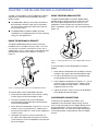
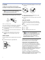
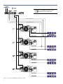
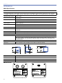
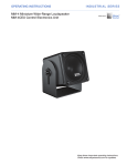
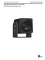
OPERATING INSTRUCTIONS MM-4 Miniature Wide-Range Loudspeaker MM-4CEU Control Electronics Unit INDUSTRIAL SERIES DECLARATION OF CONFORMITY ACCORDING TO ISO/IEC GUIDE 22 AND EN 45014 Manufacturer's Name: Meyer Sound Laboratories Inc. Manufacturer's Address: 2832 San Pablo Avenue Berkeley, California 94702-2204, USA declares that the product Product Name: MM-4CEU conforms to the following Product Specifications Safety: EN 60065:1998 EMC: EN55103-1: 1997 emission1 EN55103-2: 1997 immunity2 Supplementary Information The product herewith complies with the requirements of the Low Voltage Directive 73/23/EEC and the EMC Directive 89/336/EEC. Office of Quality Manager Berkeley, California USA March 27, 2003 European Contact: Your local Meyer Sound dealer or Meyer Sound Germany, GmbH. Carl Zeiss Strasse 13, 56751 Polch, Germany. Telephone: +49 2654 9600 58 Fax: +49 2654 9600 59 Environmental specifications for Meyer Sound Electronics products This device complies with the requirements of the Low Voltage Directive 73/23/EEC and the EMC Directive 89/336/EEC. This device also complies with EN 55103-1 & -2. Operation is subject to the following two conditions: (1) this device may not cause harmful interference, and (2) this device must accept any interference received, including interference that may cause undesired operation. Operating Temperature: Nonoperating Temperature: Humidity: Operating Altitude: Nonoperating Altitude: Shock: Vibration: 0˚ C to + 45˚ C <-40˚ C or > +75˚ C to 95% at 35˚C to 4600 m (15,000 ft) to 6300 m (25,000 ft) 30g 11 msec half-sine on each of 6 sides 10 Hz to 55 Hz (0.010 m peak-to-peak excursion) Made by Meyer Sound Laboratories Berkeley, California USA N775 MM-4CEU European Office: Meyer Sound Lab. GmbH Carl Zeiss Strasse 13 56751 Polch, Germany ® Copyright 2003 Meyer Sound. All rights reserved. Meyer Sound MM-4/MM-4CEU Operating Instructions. The contents of this manual are furnished for informational purposes only, are subject to change without notice, and should not be construed as a commitment by Meyer Sound Laboratories Inc. Meyer Sound assumes no responsibility or liability for any errors or inaccuracies that may appear in this manual. Except as permitted by applicable copyright law, no part of this publication may be reproduced, stored in a retrieval system, or transmitted, in any form or by any means, electronic, mechanical, recording or otherwise, without prior written permission from Meyer Sound. SpeakerSense and MultiSense are trademarks of Meyer Sound. Meyer Sound, Meyer Sound MAPP Online and SIM are registered trademarks of Meyer Sound. All third-party trademarks mentioned herein are the property of their respective trademark holders. Printed in the U.S.A. Part Number: 05.091.012.01 Rev. D ii SYMBOLS USED These symbols indicate important safety or operating features in this booklet and on the chassis. ! Dangerous voltages: risk of electric shock Important operating instructions Frame or chassis Protective earth ground Pour indiquer les risques résultant de tensions dangereuses Pour indequer important instructions Masse, châssis Terre de protection Zu die gefahren von gefährliche spanning zeigen Zu wichtige betriebsanweisung und unterhaltsanweisung zeigen Rahmen oder chassis Die schutzerde Para indicar voltajes peligrosos. Instrucciones importantes de funcionamiento y/o manteniento Armadura o chassis Tierra proteccionista IMPORTANT SAFETY INSTRUCTIONS 1. Read these instructions. 2. Keep these instructions. 3. Heed all warnings. 4. Follow all instructions. 11. Only use attachments/accessories specified by Meyer Sound. 12. Use only with the caster rails or rigging specified by Meyer Sound, or sold with the apparatus. Handles are for carrying only. 5. Do not use this apparatus near water. 6. Clean only with dry cloth. 7. Do not block any ventilation openings. Install in accordance with Meyer Sound's installation instructions. 8. Do not install near any heat sources such as radiators, heat registers, stoves, or other apparatus that produce heat. 9. Do not defeat the safety purpose of the groundingtype plug. A grounding-type plug has two blades and a third grounding prong. The third prong is provided for your safety. If the provided plug does not fit into your outlet, consult an electrician for replacement of the obsolete outlet. ! CAUTION: Rigging should only be carried out by experienced professionals. 13. Unplug this apparatus during lightning storms or when unused for long periods of time. 14. Refer all servicing to qualified service personnel. Servicing is required when the loudspeaker has been damaged in any way, such as the power-supply cord or plug is damaged, liquid has been spilled or objects have fallen into the apparatus, the apparatus has been exposed to rain or moisture, does not operate normally, or has been dropped. 10. Protect the power cord from being walked on or pinched particularly at plugs, convenience receptacles, and the point where they exit from the apparatus. The AC mains plug or appliance coupler shall remain readily accessible for operation. iii SAFETY SUMMARY English - To reduce the risk of electric shock, disconnect the unit from the AC mains before installing audio cable. Reconnect the power cord only after making all signal connections. - Connect the unit to a two-pole, three wire grounding mains receptacle. The receptacle must be connected to a fuse or circuit breaker. Connection to any other type of receptacle poses a shock hazard and may violate local electrical codes. - Do not allow water or any foreign object to get inside the unit. Do not put objects containing liquid on, or near, the unit. - To reduce the risk of overheating the unit, avoid exposing it to direct sunlight. Do not install the unit near heat-emitting appliances, such as a room heater or stove. - This unit contains potentially hazardous voltages. Do not attempt to disassemble the unit. The unit contains no user-serviceable parts. Repairs should be performed only by factory-trained service personnel. - Pour éviter une surchauffe de appareil, conserver-la à l’abri du soleil. Ne pas installer à proximité d’appareils dégageant de la chaleur tels que radiateurs ou appareils de chauffage. - Ce appareil contient des circuits haute tension présentant un danger. Ne jamais essayer de le démonter. Il n’y a aucun composant qui puisse être réparé par l’utilisateur. Toutes les réparations doivent être effectuées par du personnel qualifié et agréé par le constructeur. - - - - iv Pour réduire le risque d’électrocution, débrancher la prise principale de appareil, avant d’installer le câble d’interface allant à l’audio. Ne rebrancher le bloc d’alimentation qu’après avoir effectué toutes les connections. Branchez appareil dans une prise de courant à 3 dérivations (deux pôles et la terre). Cette prise doit être munie d’une protection adéquate (fusible ou coupe-circuit). Le branchement dans tout autre genre de prise pourrait entraîner un risque d’électrocution et peut constituer une infraction à la réglementation locale concernant les installations électriques. Ne pas laisser de l’eau ou tout objet pénétrer dans appareil. Ne pas placer de r´cipients contenant un liquide sur cet appareil, ni à proximité de celui-ci. - - Um die Gefahr eines elektrischen Schlages auf ein Minimum zu reduzieren, den Gerät vom Stromnetz trennen, bevor ggf. ein Audio-Schnittstellensignalk abel angeschlossen wird. Das Netzkabel erst nach Herstellung aller Signalverbindungen wieder einstecken. Der Gerät an eine geerdete zweipolige DreiphasenNetzsteckdose anschließen. Die Steckdose muß mit einem geeigneten Abzweigschutz (Sicherung oder Leistungsschalter) verbunden sein. Der Anschluß der unterbrechungsfreien Stromversorgung an einen anderen Steckdosentyp kann zu Stromschlägen führen und gegen die örtlichen Vorschriften verstoßen. Darauf achten, daß weder Wasser noch Fremdkörper in das Innere den Gerät eindringen. Keine Objekte, die Flüssigkeit enthalten, auf oder neben die unterbrechungsfreie Stromversorgung stellen. Um ein Überhitzen dem Gerät zu verhindern, das Gerät vor direkter Sonneneinstrahlung fernhalten und nicht in der Nähe von wärmeabstrahlenden Haushaltsgeräten (z.B. Heizgerät oder Herd) aufstellen. Im Inneren diesem Gerät herrschen potentiell gefährliche Spannungen. Nicht versuchen, das Gerät zu öffnen. Es enthält keine vom Benutzer reparierbaren Teile. Reparaturen dürfen nur von ausgebildetem Kundenienstpersonal durchgeführt werden. Español - Para reducir el riesgo de descarga eléctrica, desconecte de la red el aparato antes de instalar el cable de señal de audio. Vuelva a conectar el conductor flexible de alimentación solamente una vez efectuadas todas las interconexiones de señalización. - Conecte el aparato a un tomacorriente bipolar y trifilar con neutro de puesta a tierra. El tomacorriente debe estar conectado a la protección de derivación apropiada (ya sea un fusible o un disyuntor). La conexión a cualquier otro tipo de tomacorriente puede constituir peligro de descarga eléctrica y violar los códigos eléctricos locales. - No deje que en el aparato entre agua ni ningún objeto extraño. No ponga objetos con líquidos encima de la unidad ni cerca de ella. - Para reducir el riesgo de sobrecalentamiento, no exponga la unidad a los rayos directos del sol ni la instale cerca de artefactos que emiten calor, como estufas o radiadores. - Este aparato contiene niveles de voltaje peligrosos en potencia. No intente desarmar la unidad, pues no contiene piezas que puedan ser reparadas por el usuario. Las reparaciones deben efectuarse únicamente por parte del personal de mantenimiento capacitado en la fábrica. Deutsch Français - - CONTENTS Introduction The MM-4 Miniature Wide-Range Loudspeaker The MM-4CEU Control Electronics Unit 1 1 Chapter 1: Installing the MM-4 Loudspeaker 3 Using the MUB-MM4 U-Bracket Using the MFMA-MM4 Adapter Loudspeaker Connections Standard Connector Weather-Protected Connector Effect of Cable Resistance on System Performance 3 3 3 4 4 4 Chapter 2: The MM-4CEU Control Electronics Unit 5 Frequency and Phase Response Correction Driver Protection AC Power Safety Issues Line Level Inputs Line Level Outputs SpeakerSense Inputs MM-4CEU/MM-4 Connection Diagram 5 5 6 6 6 7 7 8 Chapter 3: Choosing a Power Amplifier 9 Gain Protection Circuitry Electrical Characteristics Power Supply About Bridging Controlling Zone Levels Equalization Chapter 4: System Design and Optimization Tools Meyer Sound MAPP Online SIM Measurement System Source Independent Measurement Technique Applications 9 9 9 10 10 10 10 11 11 11 12 12 Appendix A: MM-4 Weather Protected Cable Assembly Procedure 13 Appendix B: MM-4 Specifications 14 Appendix C: MM-4CEU Specifications 15 v vi INTRODUCTION INTRODUCTION As you read this manual, you’ll find figures and diagrams to help you understand and visualize what you’re reading. You’ll also find numerous icons that serve as cues to flag important information or warn you against improper or potentially harmful activities. These icons include: A NOTE identifies an important or useful piece of information relating to the topic under discussion. A TIP offers a helpful tip relevant to the topic at hand. A CAUTION gives notice that an action can have serious consequences and could cause harm to equipment or personnel, delays, or other problems. ! The MM-4 consists of a single 4-inch cone driver with a 16ohm voice coil mounted in a sealed enclosure. Connecting directly to your amplifier, the MM-4 draws 150 watts peak from the line to produce 112.5 dB peak SPL. Typically, with four MM-4 loudspeakers connected in parallel on the line, the system requires a direct drive power amplifier capable of 600 watts continuous output (49 volts rms) into 4 ohms. The MM-4's enclosure comes standard with a paintable black anodized finish. The enclosure acts as a sink to dissipate heat from the driver voice coil, and is fitted with a perforated steel grille. NOTE: The MM-4 can be ordered custompainted in any color to match your décor. A looping, sealed EN3 connector is available for outdoor installations, as well as a Phoenix-style keyed connector for indoor systems. THE MM-4CEU CONTROL ELECTRONICS UNIT THE MM-4 MINIATURE WIDE-RANGE LOUDSPEAKER The MM-4 Miniature Wide-Range loudspeaker (Figure i.1) is a very compact loudspeaker for high-quality distributed system applications. In contrast to conventional low power 70-volt transformer based systems, the MM-4 can produce wide-range high sound pressure levels while dramatically reducing distortion and easing installation requirements. A two-channel, single rack unit, the MM-4CEU Control Electronics Unit (Figure i.2) provides frequency and phase response correction circuitry tailored to the MM-4 loudspeaker. Through a SpeakerSense™ connection to the power amplifier output, the MM-4CEU continuously monitors the power applied to the drivers, activating integral peak and RMS limiters to protect against over-excursion and overheating. When several amplifiers are used in a system, the MM4CEU’s SpeakerSense connection works by utilizing Meyer Sound’s MultiSense™ technology, allowing each channel to: Drive multiple amplifiers Monitor two amplifier channels at once Activate protection circuits based on the amplifier channel with the highest signal level MultiSense allows the levels of individual zones to be adjusted using the power amplifier’s attenuators while still giving protection to all the loudspeakers on the same MM4CEU channel. Typically, each channel of the MM-4CEU can drive 12 or more amplifier channels depending on the input impedance of the amplifier. Figure i.1. MM-4 Miniature Wide-Range Loudspeaker A Power +- 15V MM-4 Controller 10 8 6 5 4 In 20 S en s e A B Lo Cut P ea k L i mit R MS Li mit B Out ∞ 10 3 6 5 4 3 2 2 1 20 1 0 A 8 Attn dB ∞ 0 B Figure i.2. The MM-4CEU Front Panel 1 INTRODUCTION The MM-4CEU is specifically designed for use in an MM-4 loudspeaker system. In conjunction with professional grade amplifiers, the MM-4CEU protects your MM-4 loudspeakers against damaging overload conditions, while ensuring that they meet their published specifications. 2 CHAPTER 1 CHAPTER 1: INSTALLING THE MM-4 LOUDSPEAKER The MM-4 accommodates a variety of different installation requirements to provide maximum flexibility. Mounting options include: The MUB-MM4 U-Bracket, which allows the MM-4 to be mounted on virtually any flat surface and enables you to change the angle of the MM-4 with respect to the mounting surface. USING THE MFMA-MM4 ADAPTER The optional MFMA-MM4 Flush Mount Adapter allows the MM-4 to be used with virtually any ceiling or in-wall flush-mount bezel designed to house an 8-inch cone loudspeaker. The kit includes two L-brackets that fit the bezel’s stud pattern, a grille mask, and associated hardware (Figure 1.2). The MFMA-MM4 Flush Mount Adapter, which fits standard 8-inch loudspeaker bezels, for flush-mounting ceiling or in-wall applications. USING THE MUB-MM4 U-BRACKET The optional MUB-MM4 U-Bracket mounts to the two threaded inserts in the MM-4 enclosure sides. It uses two 1/2" long 3/8"-16 stainless steel machine screws, two 1" rubber washers, two 1" metal washers, and neoprene strips attached to the interior to the U-Bracket, as shown in Figure 1.1. Figure 1.2. Installing the MM-4 into the optional MFMA-MM4 Flush Mount Adapter To install the MM-4 into the MFMA-MM4 Flush Mount Adapter: 1. Gently slide the loudspeaker into the adapter’s housing, seating its sides against the attached neoprene strips. 2. Line up the threaded inserts on the loudspeaker with the long guide hole on the housing. Figure 1.1. Installing the MM-4 into the optional MUB-MM4 U-Bracket To install the MM-4 into the MUB-MM4 U-Bracket: 1. Gently slide the loudspeaker into the bracket, seating its sides against the attached neoprene strips. 2. Line up the threaded inserts on the loudspeaker near the top of the long guide hole on the bracket for maximum tilting flexibility. 3. Fasten bracket to loudspeaker using two 1/2" x 3/8"-16 machine screws, ensuring that the 1" rubber washers touch the bracket and the 1" metal washers support the machine screws. 3. Fasten adapter to loudspeaker using two 1/2" x 3/8"-16 machine screws, ensuring that the 1" rubber washers touch the adapter housing and the 1" metal washers support the machine screws. 4. Tighten the machine screws to secure the loudspeaker to the adapter. Do not over-tighten. LOUDSPEAKER CONNECTIONS To realize the full capabilities of the MM-4, each loudspeaker must be fed with voltage swings up to 49 volts rms (70 volts peak) from the amplifier driving the line, with all loudspeakers in the line connected in parallel. In distributed systems, a line with four to eight loudspeakers connected in parallel is typically driven with one amplifier channel. 4. Half-tighten the machine screws to the bracket, set the angle of the loudspeaker, then tighten the machine screws further to secure the loudspeaker to the bracket. Do not over-tighten. 3 CHAPTER 1 CAUTION: The total load of the MM-4 loudspeakers connected in parallel should not be lower than the minimum allowable load of the amplifier. Otherwise, damage to the amplifier and loudspeakers may result. TIP: The chassis-mount EN3 connectors on the MM-4 rear panel are fitted with captive plastic caps. If you are not using the second connector for looping, use the cap to seal it against moisture invasion. ! Standard Connector A Phoenix-style keyed connector is fitted to the indoor version of the MM-4 (Figure 1.3). The left-hand terminal of the connector is the negative (-) and the right-hand terminal is the positive (+), when viewing the loudspeaker from the back. The connector accepts conductors up to 12 AWG (American Wire Gauge) or 2.5 mm2. Figure 1.3. Rear panel of the indoor version of the MM-4 TIP: It is possible to loop several MM-4 loudspeakers together using two wires connected to each terminal of the connector. Weather-Protected Connector Sealed EN3 connectors are fitted to the weather-protected, outdoor version of the MM-4. A dedicated input connector and a loop out connector are provided to facilitate looping several MM-4 loudspeakers together. The input connector on the loudspeaker is wired using the left-hand terminal of the connector as the negative (-) and the right-hand terminal as the positive (+) when viewing the loudspeaker from the back (Figure 1.4). The EN3 accepts conductors up to 16 AWG (1.55 mm2). EFFECT OF CABLE RESISTANCE ON SYSTEM PERFORMANCE When specifying loudspeaker cable for an MM-4 installation, it is important to take into account the total (loop) conductor resistance, since this can affect both peak SPL capability and, at the extreme, system frequency response. As a rule, MM-4 systems will exhibit 1/2 dB peak SPL loss for every ohm of total loop wiring resistance. Accordingly, 12 ohms of cable resistance will result in a 6 dB peak SPL loss. MM-4 systems can tolerate up to 20 ohms total cable resistance before the frequency response is affected. You may want to keep the loop resistance of an MM-4 system below 1 ohm to avoid loss of peak SPL capability. Tables 1.1 and 1.2 give resistance (in ohms) per 1000 feet and kilometers, respectively, per conductor for standard AWG and metric wire gauges. For total resistance, multiply the length of the cable by two (two conductors). Table 1.1 AWG Wire Resistance for Various Gauges Cable Gauge (AWG) Resistance (Ω/1000 ft) 22 17.5 20 10.9 18 6.92 16 4.35 14 2.73 12 1.71 10 1.08 Table 1.2 Metric Wire Resistance for Various Gauges Cable Gauge (mm2) Resistance (Ω/km) 0.5 33.23 0.75 22.37 1 17.11 1.5 11.25 2.5 6.75 4 4.277 6 2.864 Figure 1.4. Rear panel of the weather-protected version of the MM-4 NOTE: The EN3 displays a small dot just above Pin 1, the negative terminal. See Appendix A for more information on wiring. 4 TIP: For very long runs, you can use a larger cable for most of the length of the run, then terminate with the appropriate gauge listed above for the connector. CHAPTER 2 CHAPTER 2: THE MM-4CEU CONTROL ELECTRONICS UNIT The MM-4CEU is a required component for every MM-4 installation. It performs a number of important signalprocessing functions to ensure that the MM-4 meets its published specifications and is protected against damaging overload conditions. The MM-4CEU mounts in a standard 19-inch relay rack and occupies a single rack space (1.75 inches). Each MM-4CEU provides two channels of signal processing, both capable of driving several amplifier channels and monitoring two separate amplifier channels for protection (four amplifier channels total per MM-4CEU). Each channel of the MM4CEU features an independent signal level attenuator and low cut switch. NOTE: See Chapter 3, “Choosing a Power Amplifier,” for important details about choosing and configuring an amplifier for use with the MM-4CEU. FREQUENCY AND PHASE RESPONSE CORRECTION The MM-4CEU incorporates multiple-pole frequency response equalization circuitry that is tailored specifically to the MM-4 loudspeaker’s acoustical characteristics. This circuitry assures that the MM-4’s response remains within ±4 dB from 160 Hz to 16 kHz (free field). Integral phase response correction circuits maintain a system phase response of ±45° from 700 Hz to 17 kHz. The MM-4CEU also provides an independent frontpanel low-cut switch for each signal channel. This switch introduces a high-pass function that can be used to compensate for low-frequency boost due to half-space loading in flush-mounted configurations. It can also augment the MM-4 loudspeaker’s headroom when used with a subwoofer for music reproduction. NOTE: See the section “Equalization” in Chapter 3, “Choosing a Power Amplifier,” for more information on using the low-cut switch on the MM-4CEU. DRIVER PROTECTION The MM-4CEU features Meyer Sound’s SpeakerSense driver protection circuitry. Through a connection back from the power amplifier output, the MM-4CEU’s SpeakerSense function monitors the continuous and peak power being applied to the MM-4 drivers. Meyer Sound’s MultiSense function then allows each MM-4CEU channel to monitor two amplifier outputs, assuring that the protection circuits are activated by the signal branch with the highest gain. This allows the MM-4CEU to protect the MM-4 in the following ways: When the continuous power exceeds the MM-4’s safe limits, the MM-4CEU introduces an RMS limiter that clamps the audio signal to protect the MM-4 driver from damage due to overheating. When the peak power exceeds the MM-4’s safe limits, the MM-4CEU introduces a fast-acting peak limiter to clamp the signal level and protect the MM-4 driver from excessive excursion. The functions of the SpeakerSense circuitry are indicated on the MM-4CEU front panel by the following LEDs on each channel: Peak Limit — During peak limiting, the Peak Limit LED glows yellow. RMS Limit — During RMS limiting, the RMS Limit LED glows yellow. Sense — When sensing, the MM-4CEU may display one of two LED colors: - When the signal is sensed back through the SpeakerSense connection, the LED glows green. - When the gain of the amplifier is below 10 dB or above 30 dB, the LED flashes red, indicating that the protection will not work properly. When a channel returns to normal, limiting ceases. The LED for that channel is inactive, indicating MM-4CEU is not currently limiting. 5 CHAPTER 2 AC POWER The MM-4CEU accommodates international power standards in two ranges: 90 to 130 V AC and 180 to 260 V AC, 50/60 Hz. A rear-panel switch selects between the two. Do not use a ground-lifting adapter or cut the AC cable ground pin. CAUTION: Be sure to select the correct range for your local power standard before connecting and operating the MM-4CEU. ! Use the AC cable wiring diagram, illustrated in Figure 2.1, to create international or special-purpose power connectors: blue = neutral brown = hot yellow/green = earth ground (chassis) Figure 2.1. AC cable color codes If the colors referred to in the diagram don’t correspond to the terminals in your plug, use the following guidelines: Connect the blue wire to the terminal marked with an N or colored black. Connect the brown wire to the terminal marked with an L or colored red. Connect the green and yellow wire to the terminal marked with an E or colored green (or green and yellow). SAFETY ISSUES Pay close attention to these important electrical and safety issues. The MM-4CEU requires a grounded outlet. Earth ground Chassis ground Keep all liquids away from the MM-4CEU to avoid hazards from electrical shock. Do not operate the unit if the power cables are frayed or broken. LINE LEVEL INPUTS Each MM-4CEU input presents a 10 kOhms balanced impedance to a three-pin XLR female connector wired as follows: Pin 1 — 11 kΩ to chassis and earth ground (ESD clamped) Pin 2 — Signal + Pin 3 — Signal Case — Earth (AC) ground and chassis NOTE: Pins 2 and 3 are differentially balanced, so the polarity applied to the input XLR connectors on the MM-4CEU will be replicated on the output XLR connectors. Amplifier XLR polarity, along with its output wiring, will determine the polarity of the entire system. Use standard audio cables with XLR connectors for balanced signal sources. Telescopic grounding (Pin 1 disconnected on one end) is not recommended. A single source can drive multiple MM-4CEUs with paralleled inputs. To avoid distortion from the source, make sure the source equipment provides an adequate drive circuit design for the total paralleled load impedance presented by the paralelled processors. The input impedance for a single MM-4CEU is 10 kOhms: if n represents the number of MM-4CEUs, paralleling the inputs of n MM-4CEUs loudspeakers will produce a balanced input load of 10 kOhms divided by n. For example, cascading an array of 10 MM-4CEUs produces an input impedance of 1000 ohms (10 kOhms divided by 10), indicating that the source equipment should have an output impedance of 100 ohms or less. 6 CHAPTER 2 NOTE: Most source equipment is safe for driving loads no smaller than 10 times the source’s output impedance. For source equipment with driving capability of 600 ohms, 16 MM-4CEUs could be safely driven in parallel (10 kOhms divided by 16 equals 625). SPEAKERSENSE INPUTS For each MM-4CEU channel, connect a cable from the amplifier output to the corresponding SpeakerSense input. If you are driving multiple amplifier channels from a single MM-4CEU output and using MultiSense, connect the two amplifier output channels with the highest gain (not to exceed 30 dB of amplification gain) to a separate, corresponding SpeakerSense input. CAUTION: Shorting any input connector pin ! to the chassis can create a ground loop and cause hum. CAUTION: When using MultiSense, make sure the two amplifier channels with the highest gains are the ones connected to each of the MM-4CEU's two SpeakerSense inputs. TIP: If abnormal noise (hum, hiss, popping) is produced from the loudspeaker, disconnect the audio source from the MM-4CEU. If the noise stops, the problem is not with the MM-4CEU; check the audio input and AC power. CAUTION: When using MultiSense, both amplifier outputs MUST be connected with the same polarity. Observe the polarity labels on the MM-4CEU rear panel. ! ! LINE LEVEL OUTPUTS MM-4CEU/MM-4 CONNECTION DIAGRAM The MM-4CEU features push-pull outputs capable of driving 600 ohms and using three-pin XLR male connectors wired as follows: Figure 2.2 on the following page illustrates a typical MM4CEU connection using four 2-channel amplifiers and 32 MM-4 loudspeakers. Pin 1 — Earth ground/chassis Pin 2 — Signal + Pin 3 — Signal - NOTE: The MM-4CEU is a balanced passthrough device (balanced signal in - balanced signal out) and therefore has no effect on the polarity of the signal it receives. Amplifier XLR polarity, along with its output wiring, will determine the polarity of the entire system. Use standard audio cables with XLR connectors for driving balanced signal inputs. Telescopic grounding (pin 1 disconnected on one end) is not recommended. Each MM-4CEU output can drive multiple power amplifier signal inputs in parallel, to a minimum load impedance of 600 ohms. Refer to your power amplifier specifications to determine input impedance and calculate the net impedance of multiple paralleled amplifier inputs. For example, one channel of a MM-4CEU could drive 20 amplifier channels with 12 kOhms input impedance (600 ohms total impedance). 7 CHAPTER 2 NOTE: Amplifiers #1 and #2 are the amplifiers with the highest gain. Channel 2 SpeakerSense Channel 1 SpeakerSense Figure 2.2. Connecting the MM-4CEU Control Electronics Unit 8 CHAPTER 3 CHAPTER 3: CHOOSING A POWER AMPLIFIER The MM-4 is designed for high-quality distributed sound systems. To realize the MM-4’s full capabilities, a directdrive power amplifier capable of 49 volts rms (70 volts peak) at the rated load impedance presented by the line configuration is required. The MM-4 presents a nominal load of 16 ohms, and each unit must be wired in parallel with the line. As shown in Table 4.1, the number of MM4 loudspeakers on a given signal branch can be used to determine the required power rating for the corresponding amplifier. NOTE: Some manufacturers express the gain of their amplifiers in voltage gain as a factor instead of gain in dB. To covert the voltage gain in dB, use the following equation: Gain (in dB) = 20 Log (Voltage Gain) For example, a voltage gain of "x20" equates to 26 dB of gain. PROTECTION CIRCUITRY Table 3.1 Amplifier Power Number of MM-4 Loudspeakers Continuous Power Rating 1 (16 Ω load) 150 W 2 (8 Ω load) 300 W 3 (5.3 Ω load) 450 W 4 (4 Ω load) 600 W 8 (2 Ω load) 1200 W CAUTION: The total load of the MM-4 loudspeakers connected in parallel should not be lower than the minimum allowable load of the amplifier. Otherwise, damage to the amplifier and loudspeakers may result. ! The following sections discuss important criteria for choosing and configuring power amplifiers for use with an MM-4 and MM-4CEU distributed system. GAIN The gain setting of the power amplifier is crucial to system performance: if the gain is set too low, “upstream” equipment may clip before the amplifier reaches full power. Conversely, if the gain is set too high, not only will system noise increase, the amplifier is capable of overcoming the MM-4CEU’s protection circuits and may damage the loudspeakers. The MM-4CEU is designed to work with amplifiers having gain of between 10 dB and 30 dB. NOTE: The optimal amplifier gain setting for the MM-4CEU is 20 dB. The gain of an amplifier can be measured with an rms volt meter by feeding the amplifier with a tone generator at 1 kHz and measuring the input voltage going in (V in) and the voltage delivered at the output (V out) and applying the following expression: Avoid amplifiers with extra “sensing” connections for load protection; the MM-4CEU incorporates all the protection circuitry necessary for reliable performance. A basic, reliable, professional grade amplifier is all that is required. The amplifier must be AC coupled to the load (i.e. protected from producing DC at its output). The MM-4 is directly coupled to the distribution line, and any significant DC voltage on the line may damage the driver. A relay or crowbar circuit to open or short the amplifier output in fault conditions are preferred. ELECTRICAL CHARACTERISTICS Slew rate should be at least 10 volts/microsecond; 30 volts/ microsecond or better is preferred. The amplifier must be stable under all load conditions — shorted, open, inductive or capacitive. Hum and noise should be such that when the amplifier input is shorted, noise from the loudspeaker is indiscernible. Distortion (THD or IM) should be equal to or better than 0.01 percent. Balanced inputs are required. Input connectors should be XLR-type (preferred) or TRS (tip, ring, sleeve) type 1/4-inch phone female connectors. The MM-4CEU is a balanced pass-through device (balanced signal in - balanced signal out) and therefore has no effect on the polarity of the signal it receives. Amplifier XLR polarity, along with its output wiring, will determine the polarity of the entire system. For example, an amplifier with input as Pin 2 (+) and Pin 3 (-) on the XLR connector, with the output terminal (+) of the amplifier connected to the terminal (+) of the MM4 loudspeaker connector, will produce a positive pressure pulse when a positive voltage pulse is applied to Pin 2 of the MM-4CEU input XLR. Gain (in dB) = 20 Log (V out / V in) 9 CHAPTER 3 POWER SUPPLY Some amplifiers are designed so that the internal power supply rails sag as the load current increases. While the amplifier’s rated continuous output at a given load may appear high, its peak output voltage varies with the load impedance. Because a loudspeaker’s impedance changes with frequency, such an amplifier will clip prematurely at low points in the loudspeaker’s impedance curve, and may deliver too high a voltage at high impedance points. Both possibilities are potentially damaging to the loudspeaker. A “stiff” power supply therefore assures the best performance. One indicator of a stiff supply is that the amplifier’s wattage rating doubles each time the load impedance is halved (as shown in Table 3.1). An amplifier’s supply is sufficiently stiff for the MM-4 if its no-load peak output (at clipping) drops no more than 5 volts when the amplifier is connected to an 8-ohm load. ABOUT BRIDGING When a power amplifier operates in bridged mode, the polarity of one output is reversed with respect to the other output, and both are fed the same input signal. The load is connected between the channel 1 and channel 2 “hot” terminals. If you wish to use bridged amplifiers in your MM-4 system, check your amplifier’s documentation to make sure which input is used for signal, and which is the + output terminal (positive voltage out for positive input voltage applied). CAUTION: In bridged mode, an amplifier's minimum allowable load is twice that of each output in dual channel configuration. For example, if an amplifier is rated for a 4-ohm load, then the minimum in bridged mode should be 8 ohms. Trying to drive a 4-ohm load with such an amplifier in bridged mode will cause “current clipping” and could damage the loudspeakers. ! CONTROLLING ZONE LEVELS In a typical MM-4 distributed installation, there are two options for adjusting the level in a coverage zone: 1. The corresponding MM-4CEU “Attn dB” control (input attenuation), which will adjust the level of all the amplifiers fed by that channel of the processor 2. The corresponding amplifier channel attenuators, which will adjust the level of all the loudspeakers fed by that amplifier channel With the amplifier attenuators set to maximum (making sure the gain does not exceed 30 dB), first use the MM-4CEU 10 level controls to set zone levels. Where a single MM-4CEU channel controls several zones (using MultiSense), use the individual amplifier channel attenuators to adjust individual zones. CAUTION: When using multiple amplifiers and if adjustments are made on the amplifier channels, make sure that the two amplifier channels with the highest gains are the ones connected to each of the MM-4CEU's two SpeakerSense inputs. ! EQUALIZATION For best results, the Meyer Sound CP-10 Parametric Equalizer is recommended; for high-resolution measurement (strongly recommended), the preferred tool is Meyer Sound’s SIM®. Equalize zones individually, where adjacent zones overlap significantly (which is not normally preferred in distributed systems), checking the overlap zone and adjusting as necessary to provide the smoothest transition between zones. When the MM-4 is mounted against a wall surface or in a flush-mounting bezel, half-space loading may cause low-frequency extension and boost. In voice-only paging systems, low-frequency boost is to be avoided, since it can harm intelligibility. Use the MM-4CEU Lo-Cut switch to compensate for half-space loading effects. The Lo-Cut switch may also be used to increase headroom when the MM-4 is used with subwoofers for music reinforcement. Consult your subwoofer’s documentation for detailed information about crossover optimization. TIP: Systems with subwoofers will almost always require high-resolution measurement and equalization to achieve the best results, because low frequencies are most affected by boundary conditions and localized acoustic phenomena such as resonance. CHAPTER 4 CHAPTER 4: SYSTEM DESIGN AND OPTIMIZATION TOOLS Meyer Sound offers two intuitive, comprehensive tools to assist you with the acoustical and functional requirements and optimization of any system design. This chapter introduces you to the Meyer Sound MAPP Online® acoustical prediction tool; and SIM®, a robust instrumentation package for system measurement, analysis, and more. MEYER SOUND MAPP ONLINE MAPP Online is a powerful, cross-platform, Java-based application for accurately predicting the coverage pattern, frequency response, impulse response, and maximum SPL output of single or arrayed Meyer Sound loudspeakers. Residing on your computer, MAPP Online facilitates configuring arrays of a wide variety of Meyer Sound products and, optionally, defines the environment in which they will operate, including air temperature, pressure, and humidity, as well as the location and composition of walls. You can find MAPP Online at: www.meyersound.com/products/software/mapponline NOTE: In order to use MAPP Online, you will need to register by clicking “Apply for MAPP Online” on the Web page listed above. After registration and upon approval, an e-mail will be sent to you with a username and password along with the address for the Web page where you can download MAPP Online. Instructions will guide you through the download and setup process. As its name indicates, MAPP Online is an Internet-based application: when a prediction is requested, data is sent over the Internet to a high-powered server at Meyer Sound that runs a sophisticated acoustical prediction algorithm using high-resolution, complex (magnitude and phase) polar data. Predicted responses are returned over the Internet and displayed on your computer. With MAPP Online, you can: Plan an entire portable or fixed loudspeaker system and determine delay settings for fill loudspeakers. Clearly see interactions among loudspeakers and minimize destructive interference. Place microphones anywhere in the sound field and predict the frequency response, impulse response, and sound pressure level at the microphone position using MAPP Online’s Virtual SIM feature. Refine your system design to provide the best coverage of the intended audience area. Use a Virtual VX-1 Program Equalizer to predetermine the correct control settings for best system response. MAPP Online enables you to come to an installation prepared with a wealth of information that ensures the system will satisfy your requirements “out of the box” – including basic system delay and equalization settings. Its accurate, high-resolution predictions eliminate unexpected onsite adjustments and coverage problems. With MAPP Online, every sound system installation has a maximum chance of success. MAPP Online is compatible with Windows, Linux, Unix, and Apple Macintosh computers running Mac OS X version 10.1.2 or higher. The MAPP Online Web page lists additional system requirements and recommendations. SIM MEASUREMENT SYSTEM SIM is a measurement and instrumentation system including a selection of hardware and software options, microphones and accessory cables. SIM is optimized for making audio frequency measurements of an acoustical system with a resolution of up to 1/24th of an octave; the high resolution enables you to apply precise electronic corrections to adjust system response using frequency and phase (time) domain information. 11 CHAPTER 4 Source Independent Measurement Technique SIM implements the Meyer Sound source independent measurement technique, a dual-channel method that accommodates statistically unpredictable excitation signals. Any excitation signal that encompasses the frequency range of interest (even intermittently) may be used to obtain highly accurate measurements of acoustical or electronic systems. For example, concert halls and loudspeaker systems may be characterized during a musical performance using the program as the test signal, allowing you to: View measurement data as amplitude versus time (impulse response) or amplitude and phase versus frequency (frequency response) Utilize a single-channel spectrum mode View frequency domain data with a logarithmic frequency axis Determine and internally compensate for propagation delays using SIM Delay Finder function Applications The main application of SIM is loudspeaker system testing and alignment. This includes: Measuring propagation delay between the subsystems to set correct polarities and set very precise delay times Measuring variations in frequency response caused by the acoustical environment and the placement and interaction of the loudspeakers to set corrective equalization Optimizing subwoofer integration Optimizing loudspeaker arrays SIM can also be used in the following applications: Microphone calibration and equalization Architectural acoustics Transducer evaluation and correction Echo detection and analysis Vibration analysis Underwater acoustics 12 APPENDIX A APPENDIX A MM-4 Weather Protected Cable Assembly Procedure ���� �������� ���� ���� ��������� ����� ����� ����� ������� ������� ���� ���� �� ���� ��� ��� �� ��� ����� ������� ��� ����� ����� ����� �������� ��� �������� ���� �� ��� ����� ��� �������� ������ ���� ��������� ����� ��� ���� � ���� ���� ������ ���������� �� �� �� ����� �� ����� ������� ���� ���� �� ����� ����� �� ����� ��� ������ ���������� �� ����� ����� ��� � �� �������� ��� ��� ��� � �� �������� ��� ���� ��������� ���� ��������� ��� �������� ���� ��� ���� ����� ���� �� ����� �������� ���� ���� ���� ���� ����������� ���� ������� ��� ���� ��� �������� ���� ���� ���� ���������� ����� ����� ���� ���� �� ���� ��� ����� ����� ������� ������ ����� �� ����� ���� ��� ��������� ���� ��� ���� ��� ��� ������ ���� ����� ������������� ���� �� ���� ��� ���� ��� ��� ��� ������ �� ���� ������� ���� ��� ����� ����� �������� 13 APPENDIX B APPENDIX B MM-4 Specifications Acoustical Note: To realize the MM-4's full capabilities, an MM-4CEU is required. The amplifier driving the loudspeakers should be capable of 49 volts RMS at the rated load impedance, and provide a voltage gain between 10 and 30 dB (20 dB for optimal S/N ratio and protection). The power rating of the amplifier should be as follows: 1 MM-4/ch (16 Ω): 150 W; 2 MM-4/ch (8 Ω): 300 W; 4 MM-4/ch (4 Ω): 600 W; 8 MM-4/ch (2 Ω): 1200 W Operating frequency range 120 Hz - 18 kHz Note: Recommended maximum operating frequency range. Response depends on loading conditions and room acoustics. Frequency response 160 Hz - 16 kHz ±4 dB Note: Free field, measured with one-third octave frequency resolution at 4 meters. Phase response 700 Hz - 17 kHz ±45° Maximum peak SPL 112.5 dB Note: Measured with pink noise at 1 meter. Maximum continouos SPL 100 dB Note: Measured at 1 meter, driven continuously for two hours with pink noise signal having a 12.5 dB peakaverage ratio. Horizontal coverage 80° (3 kHz - 14 kHz ±10°); 120° (below 2 kHz) Vertical coverage 80° (3 kHz - 14 kHz ±10°); 120° (below 2 kHz) Transducer One 4" cone driver; Nominal impedance: 16 Ω; Voice coil size: 0.75"; Power-handling capability: 100 W (AES) ���� ��������� ���� ��������� Note: Power handling is measured under AES standard conditions: transducer driven continuously for two hours with band-limited noise signal having a 6 dB peak-average ratio. Aluminum enclosure dissipates heat generated by driver. Physical Dimensions 4.00" H x 4.00" W x 4.20" D excluding connector (102 mm x 102 mm x 107 mm) ���� �������� ���� ��������� ���� ��������� ���� �������� ���� ��������� ���� ��������� Weight 3 lbs 14 oz (1.76 kg) Enclosure Extruded aluminum Finish Black anodized; custom color available Protective grille Perforated metal screen ���� �������� ���� ��������� ���� �������� ���� ��������� MM-4 Rear Panels Weather-protected version: EN3 Connector 14 ���� ��������� Indoor version: Phoenix-Style Connector ���� ��������� APPENDIX C APPENDIX C MM-4CEU Specifications Audio Input Type Differential, electronically balanced; RF and transient protected Max common mode range ±15 V DC, clamped to earth for voltage transient protection Connector(s) Two female XLR, one for each input channel Input Impedance 10 kΩ differential between pins 2 and 3 Wiring Pin 1: Chassis/earth through 11 kΩ, 1000 pF, 15 V clamp network to provide virtual ground lift at audio frequencies; Pin 2: Signal +; Pin 3: Signal -; Case: Earth ground and chassis DC blocking None CMRR >60 dB, typically 80 dB (50 Hz - 1 kHz) RF Filter Common mode 850 kHz; differential mode 370 kHz Input Level Maximum input voltage 25 V peak-peak (+21 dBu sine wave) Audio Output Type Active push-pull, electronically balanced, capable of driving 600 Ω Load; RF & transient protected Out voltage Maximum 50 V peak-peak (+27 dBu sine wave) Connectors Two male XLR, one for each output channel Output impedance 200 Ω differential between pins 2 and 3 Wiring Pin 1: Chassis/earth; Pin 2: Signal +; Pin 3: Signal - Audio Performance Hum and noise <-90 dBV (A-weighted) Dynamic range >115 dB THD < 0.01%, typically <.002% Response accuracy <0.25 dB (20-20 kHz) AC Power Connector IEC 320 Voltage selection Switch selectable on rear panel UL/CE rated voltage 90 - 130 V AC; 180 - 260 V AC; 50/60 Hz Current draw 0.25 A max (rear panel T 250 mA fuse protected) Physical LED Indicators Sense Threshold/Gain Detect: (2) Red/Green LEDs, one per channel; RMS Limiters: (2) Yellow LEDs, one per channel; Peak Limiters: (2) Yellow LEDs, one per channel; Power: (1) Green LED Front panel: (2) Rotary input attenuators, one per channel; (2) Recessed low cut filter switches, one per channel; (1) AC power latching push switch Controls Rear Panel: (1) AC voltage selector, recessed; (1) T250V fuse and holder SpeakerSense connectors MultiSense, (4) dual banana, two per channel Note: When using multiple sense lines, all lines must be in same electrical polarity. Weight 19.00" W x 1.75" H x 7.75" D standard rack mount (482 mm x 44 mm x 197 mm) Finish Peakpowder Limit Black, coated A B Lo Cut RMS Limit Power MM-4CEU Front & Rear Panels MM-4 Controller � �� � � � � � � �� Sense � � B �� � � Out Peak Limit A B Lo Cut RMS Limit In � � � B Attn dB A �� � � � �� � � � � � � � � � � -15V �� Sense B A � � � � � � � ����� � � ��� � ��� � Out �� � � A � Attn dB � B � ���� ��� � � ����� � � � ��� � � � � � ���� ��� � ����� ����� � In A MM-4 Controller � � � -15V Power �� ��� � � ������ � ������ ���� ������� ������ �� ������� � 15 � � ���� ��� ���� ��� � ����� ������� ������ �� ������ ���� 16 17 Meyer Sound Laboratories Inc. 2832 San Pablo Avenue Berkeley, CA 94702 USA T: +1 510 486.1166 F: +1 510 486.8356 [email protected] www.meyersound.com © 2003 Meyer Sound Laboratories Inc. All Rights Reserved 05.091.012.01 Rev. D