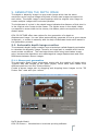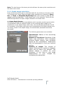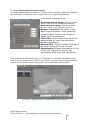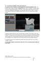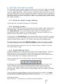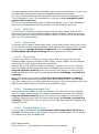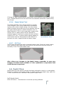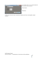
1
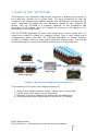
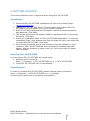
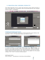
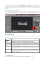
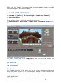
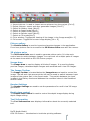
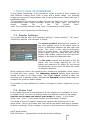
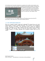
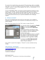
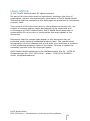
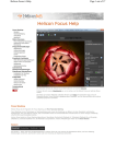
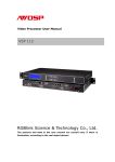
1.11.2013
DECS
MEDIA
GMBH
OCU 3D PICTURE 1.0.0 USER
GUIDE
INTRODUCTION TO LENTICULAR PRINTING SOFTWARE | Ingo Schiller
DeCS Media GmbH
OCU 3D Picture – Introduction to lenticular printing software
1
INTRODUCTION TO LENTICULAR PRINTING SOFTWARE
TABLE OF CONTENTS
1. WHAT IS OCU 3D PICTURE .................................................................... 4
2. GETTING STARTED ............................................................................... 5
Installation .......................................................................................... 5
Running OCU 3D PICTURE ..................................................................... 5
Uninstallation ....................................................................................... 5
3. CREATING AND OPENING PROJECTS ....................................................... 6
Creating and Opening Projects ............................................................... 6
Adding Images to Projects ..................................................................... 7
4. THE USER INTERFACE ........................................................................... 8
The Menubar ........................................................................................ 8
The Toolbar.......................................................................................... 8
Picture gallery ...................................................................................... 9
3D picture pairs .................................................................................... 9
Image Area .......................................................................................... 9
The Image Toolbar ................................................................................ 9
Render Settings .................................................................................... 9
Depth view control ................................................................................ 9
Tool Information ................................................................................... 9
5. GENERATING THE DEPTH IMAGE ............................................................ 10
5.1. Automatic depth image creation........................................................ 10
5.1.1. Stereo pair generation ............................................................... 10
5.1.2. Depth image calculation ............................................................. 11
5. 2. Manuel depth map generation ......................................................... 13
6. EDITING THE DEPTH IMAGE................................................................... 14
6.1.
Rules for depth image editing ......................................................... 14
6.2.
Viewing modes ............................................................................. 14
6.3.
Depth Editing Tools ....................................................................... 14
6.3.1.
Pick Tool ................................................................................. 15
6.3.2.
Brush Tool .............................................................................. 15
6.3.3.
Clone Tool .............................................................................. 15
6.3.4.
Rectangular Select Tool ............................................................ 15
6.3.5.
Polygon Select Tool .................................................................. 15
6.3.6.
Fill Tool .................................................................................. 16
6.4.
Depth Filters ................................................................................. 16
DeCS Media GmbH
OCU 3D Picture – Introduction to lenticular printing software
2
7. MULTI-VIEW 3D RENDERING................................................................ 18
7.1.
Render Settings ............................................................................ 18
7.2.
Frame Tool ................................................................................... 18
8. 3D PICTURE DISPLAY ............................................................................ 19
9. IMAGE EXPORT .................................................................................... 20
TECHNICAL SUPPORT ............................................................................... 20
LEGAL NOTICE ......................................................................................... 21
DeCS Media GmbH
OCU 3D Picture – Introduction to lenticular printing software
3
1. WHAT IS OCU 3D PICTURE
3D images are very attractive and become the focus of attention and remain in
the customers’ memory for a longer time. The only possibilities to view 3D
images are 3D displays with glasses, glasses-free 3D displays and lenticular 3D
prints. Lenticular 3D images are very attractive, thanks to their amazing 3D
effects. OCU 3D PICTURE is a powerful software for the preparation and
generation of 3D images which are suitable for viewing on 3D displays or for
generating 3D lenticular prints.
OCU 3D PICTURE generates 3D multi-view images from a stereo image pair or a
single color image by means of a disparity image. From a color image and a
corresponding depth map OCU 3D PICTURE generates an almost arbitrary
number of images, which all have slightly different viewing angle. This process
models shooting of a scene from different points across a horizontal line.
F IGURE 1: APPLICATION PRINCIPLE AND WORKFLOW
The procedure of 3D multi-view image generation is:
1.
2.
3.
4.
Open source images (original image + depth map or stereo pair)
Create and correct depth map (if necessary)
Generate a series of images from image pair and depth map
Save generated multi-view images for printing or 3D display
DeCS Media GmbH
OCU 3D Picture – Introduction to lenticular printing software
4
2. GETTING STARTED
This section explains how to install and start using OCU 3D PICTURE.
Installation
1. Download OCU 3D PICTURE installation file from the product's page
(www.decsmedia.de).
2. Launch OCU 3D PICTURE Setup. For that launch the program OCU 3D
PICTURE-x.x.x.exe (where x.x.x is the version number).
3. OCU 3D PICTURE setup window will appear. Read the recommendations
and warnings. Click Next.
4. The license agreement will appear. Read the agreement and if you accept
the terms. Click Next.
5. Select the installation folder for OCU 3D PICTURE application. To select an
installation folder, click Browser and find the folder to which you would like
to install OCU 3D PICTURE. Click Next.
6. When setup is finished, and all the necessary files are installed on your
computer, OCU 3D PICTURE has been successfully installed dialog will
appear, and the program is ready to be run. You do not need to reboot
your computer.
Running OCU 3D PICTURE
You can launch OCU 3D PICTURE by several ways:
1. Execute menu command:
Start -> Programs -> OCU 3D PICTURE x.x.x -> OCU 3D PICTURE
2. Click OCU 3D PICTURE icon on the desktop.
Uninstallation
In order to uninstall OCU 3D PICTURE, please, execute menu command:
Start -> Programs -> OCU 3D PICTURE x.x.x -> Uninstall
Follow further instructions to complete uninstallation.
DeCS Media GmbH
OCU 3D Picture – Introduction to lenticular printing software
5
3. CREATING AND OPENING PROJECTS
This section describes how to create new and how to open existing projects in
OCU 3D PICTURE. After the application OCU 3D PICTURE starts the user interface
shown in Figure is presented.
F IGURE 2: STARTING SCREEN OF APPLICATION
Creating and Opening Projects
You have the choice between opening an existing application and creating a new
application. Click on the appropriate field in the welcome screen.
F IGURE 3: OPENING AN EXISTING PROJECT OR CREATING A NEW ONE
To continue working on a previously saved project click “Open Project” and
browse for the project directory with the file browser after clicking on “Browse”.
Recently used projects will appear in the “Recent projects” control at the bottom.
Simply select the project and the other values will be loaded from the project
settings. Click “Finish” to load the selected project.
DeCS Media GmbH
OCU 3D Picture – Introduction to lenticular printing software
6
To start a new project, click on “New Project”. This opens another window, in
which you can specify where you want to store your project and what name and
description you want to include in the project. Click “Finish” to create the new
project.
Adding Images to Projects
After a project has been created or opened, it is possible to fill the Picture Gallery
with photos. To add photos to the projects’ gallery select File->Import from the
menubar or press Ctrl+I.
F IGURE 4: PICTURE LOADING IN THE PICTURE GALLERY , THE GALLERY IS MARKED
WITH A RED ARROW .
A new dialog will appear which allows selecting multiple image files, which will be
added to the project. The following image file formats are supported (among
others).
Image
Format
Description
bmp
A lossless file format for bitmap images without data
compression.
A compressed file format for bitmap images.
A file format for graphic images with indexed color palette.
A lossless file format for bitmap graphic information using
some compression.
A lossless file format for bitmap images with some
compression. Tiff file is in average two times smaller than bmp
file.
A file format for bitmap images, used in Fuji FinePix REAL 3D
W1 3D camera. It contains 2 images in jpg format with special
technical information.
jpeg
gif
png
tiff
mpo
DeCS Media GmbH
OCU 3D Picture – Introduction to lenticular printing software
7
After you click “Open”, the images files are imported and shown as small
preview images in the Picture Gallery.
4. THE USER INTERFACE
The user interface is split in nine panels or areas:
1. Menubar, 2. Toolbar, 3. 3D Picture Pairs, 4. Depth View Control, 5.
Render Settings, 6. Image Area, 7. Image Toolbar, 8. Picture Gallery and
9. Tool Information.
There are five modes in which the application can be set:
1. Gallery mode, 2. Input mode, 3. Depth mode, 4. Rendered mode and 5.
3D mode
F IGURE 5: THE USER INTERFACE
The main working area is the Image Area. Here you can view images and
modify the depth map using the tools.
The Menubar
The Menubar holds drop-down menus for file operations, Tools and to show or
hide control panels.
The Toolbar
The Toolbar is located in the upper part of the screen just below the system
menu and offers shortcuts to file operation and is used to switch between the
application’s modes. The Toolbar contains the following elements:
DeCS Media GmbH
OCU 3D Picture – Introduction to lenticular printing software
8
1.
8.
1.
2.
3.
4.
5.
6.
7.
8.
9.
2.
9.
3.
4.
5.
6.
7.
Import picture: is used to import source pictures into the project [Ctrl+I]
Export pictures: export and save generated images [Ctrl+E]
Switch to Gallery mode [Alt+G]
Switch to Input mode [Alt+I]
Switch to Depth mode [Alt+D]
Switch to Render mode [Alt+R]
Switch to 3D mode[Alt+3]
Fit to window: Toggles the viewing of the image in the Image area[Alt + F]
Full screen: Toggles full screen image display [Alt + E]
Picture gallery
The Picture Gallery is used to import and preview images in the application.
From here pictures can be moved to the 3D Picture Pairs area with the mouse.
3D picture pairs
The 3D Picture Pairs area is used to generate picture pairs. It is the main
control area to switch between images. You can work on multiple pairs of images
at the same time within a OCU 3D Picture project.
Image Area
The Image Area is used to display all kinds of images. It is used to display
preview images, calculated depth images and rendered multi-view 3D images.
The Image Toolbar
The Image Toolbar is located below the Image Area and used to control the
image. The left and right arrows at the left can be used to switch between input
images of the picture pair in the Input mode. They switch between the input
images in the Gallery mode and between the rendered views in the Rendered
and 3D mode.
Render Settings
The Render Settings are used to set the parameters for multi-view 3D image
generation.
Depth view control
The Depth View Control is used to control the depth image display during
depth image editing.
Tool Information
The Tool Information area displays information about the currently selected
tool.
DeCS Media GmbH
OCU 3D Picture – Introduction to lenticular printing software
9
5. GENERATING THE DEPTH IMAGE
The depth or disparity image is a gray-scale image which has the same
resolution as the original image and pixels of these two images correspond to
each other. The depth image is used together with the original color image to
create multiple images with horizontal parallax.
The brightness of a pixel in the depth image indicates the distance of this pixel in
in the original color image to the viewer. The lighter areas in the depth image
correspond to areas closer to the viewer, the darker pixels correspond to more
distant areas.
OCU 3D PICTURE offers two options for the generation of a depth or
displacement image. You can either automatically generate it from a given stereo
image pair, or create it manually with the help of dedicated tools which assist in
the generation process.
5.1. Automatic depth image creation
The automatic depth image creation uses a technique called disparity estimation
to calculate the disparity image. Therefor an image pair is needed which has to
meet certain conditions. The used algorithms allow using hand-taken image
pairs, because the algorithms are robust against image displacement and color
differences between stereo images.
5.1.1. Stereo pair generation
The automatic depth image generation starts with the creation of image pairs.
Therefor add two images of the same object, which have been taken from
different positions into the “Picture Gallery”.
Create a stereo image pair by dragging and dropping these images to the “3D
Picture Pair” area with your mouse.
F IGURE 6: CREATING 3D STEREO IMAGE PAIRS
DeCS Media GmbH
OCU 3D Picture – Introduction to lenticular printing software
10
Note: The two frames of a stereo pair should have the same pixel resolution and
the same color mode
5.1.2. Depth image calculation
First choose the picture pair to estimate depth for by clicking on the pair in the
“3D Picture Pairs” area. Start the depth image calculation by selecting: Menu
bar -> Tools -> Calculate Depth Map with your mouse. A pop-up will
appear and the algorithm: “linear depth map” is pre-selected. There are two
different algorithms for depth image calculation to choose from:
1. Linear Depth Image:
The default settings are recommendations which normally produce good results.
The parameter with the highest impact on the resulting depth image is the
smoothness. If the depth image looks noisy, the smoothness parameter should
be increased. If the depth map looks over-smoothed and the object borders are
not clearly visible in the depth image, the smoothness parameter should be
decreased.
The following parameters are available:
Smoothness: Radius of the smoothing
filter in pixel.
Number of iterations: Iterations of the
depth map estimation. More iterations
produce better results, less iterations
speed up the computation. Experiment
with this parameter to find your optimal
setting.
Number of warps: The number of
warps influences the maximum disparity
which can be taken into account. The
default setting is perfect for most
situations. If you have a very large
displacement
in
your
images
try
increasing the parameter.
DeCS Media GmbH
OCU 3D Picture – Introduction to lenticular printing software
11
2. Large Displacement Depth Image:
The large displacement estimator is, as the name indicates, especially suited for
the estimation of disparity from images with very large displacements.
The available parameters are:
Horizontal search range: Sets the search
range in pixel in the horizontal direction.
Vertical search range: Sets the search
range in pixel in the vertical direction.
Number of iteration: Iterations of the
depth map estimation. More iterations
produce better results, less iterations
speed up the computation.
Color filter: Color aware filtering of the
depth image for noise removal which
border preservation.
Median filter: Simple median filtering of
the depth image for noise removal.
Optimization: Global optimization of the
result, will improve the result, but
significantly slow down the calculation.
After setting the parameters click on “Calculate” to calculate the depth image
with the given parameters. Click on the “Depth” symbol in the toolbar to take a
look at the generated depth image after the computation has finished.
F IGURE 7: AUTOMATICALLY GENERATED DEPTH IMAGE
DeCS Media GmbH
OCU 3D Picture – Introduction to lenticular printing software
12
5. 2. Manuel depth map generation
If no image pair is available it is also possible to generate the depth map
manually by hand. Therefor add the image from the picture gallery to the “3D
picture Pairs” area to create a virtual 3D picture pair. In Figure a virtual image
pair with one image is shown on the left. Click on the image pair and the blue
border will appear to indicate that it is selected. Click on the “Depth” symbol in
the toolbar to switch to the depth editing mode and start creating your depth
image.
F IGURE 8: M ANUAL DEPTH IMAGE CREATION FROM A SINGLE IMAGE
Creating a depth image is much like drawing an image from scratch. With the
difference that you are not drawing color values such as red and green but depth
values, i.e. distances to the camera. As pointed out elsewhere in this document
depth values are represented as distances of objects in the image to the viewer
of the image (you), respectively the camera with which the image was taken.
The depth values can be edited and created using the tools from the “Image
Toolbar” control.
In the next chapter, the further steps to create a manual depth map are
described.
DeCS Media GmbH
OCU 3D Picture – Introduction to lenticular printing software
13
6. EDITING THE DEPTH IMAGE
The necessity to edit a depth image can arise if only one color image is available
or if the calculated depth image does not meet the required quality for multiview 3D image generation. The two cases are different in the way the in the first
case you start with an empty image which makes it difficult to get a feeling for
the depth values you have to assign to objects. It is much easier to start with a
depth map and just correct the areas in which the estimation was unsure about
the object’s distance.
6.1. Rules for depth image editing
//todo Hilfe fuer manuelles Erstellen der Tiefenkarte
6.2. Viewing modes
There are three viewing modes which assist you in the depth image creation and
editing process. They can be activated in the “Depth view Control”. The first is
the “View Interval”. The main purpose of this mode is to emphasize the
contrast of the depth values in the chosen interval. Choose the values to your
taste to focus on the depth values you are editing.
The second is the “Blend-Mode” which blends depth and color image. It creates
a transparent overlay of the depth map over the color image, which is especially
useful for object border editing. The “alpha” value sets the blending factor.
The third mode is the so-called “Replace-Mode” in which all values not within
the interval between “Min” and “Max” are replaced by the color image values.
Note that these three modes are only for viewing and do not affect or modify
your actual depth image.
6.3. Depth Editing Tools
Editing the depth map is done using the tools in the “Image Toolbar”. Tools are
displayed when they are available. Depth editing tools are displayed in the
Depth-Mode and for example the Frame-Tool is displayed in the rendered view
mode to allow selection of image regions for export.
Tools are selected in the “Image Toolbar” below the image by clicking on the
“Tools” button.
All changes done with tools can be undone and redone using the “Undo” and
“Redo” buttons. Importing and exporting depth images is done using the
“Import” and “Export” buttons which allows editing the depth image using
external tools. Button “Save” saves the edited depth map and makes it available
for rendering.
There are several handling features which are common to all tools. The right
mouse button switches between modes of the tool, e.g. in the brush tool
DeCS Media GmbH
OCU 3D Picture – Introduction to lenticular printing software
14
the right mouse button switches between value picking and drawing. In the clone
tool the right mouse button switches between selection and cloning.
If a tool is selected options and information about the tool are displayed in the
“Tool Information” area. The selected tool is shown and to change the tools
options click in the icon.
The currently selected depth value is always displayed in the “Tool Information”
area so you always know with which depth you are drawing right now.
6.3.1.
Pick Tool
6.3.2.
Brush Tool
6.3.3.
Clone Tool
The Pick tool is used to pick depth value from the depth image and set it for
other tools to use. It also gives information about the depth values by moving
the mouse over the image. Select a depth value by clicking on the depth image
with your left mouse button.
The brush tool is used to draw depth value in the depth image using your mouse.
It will use the currently selected depth value selected with the pick tool. Use the
mouse wheel to change the size of the brush. You can switch between
picking depth values and drawing with the right mouse button.
The clone tool lets you select an image region with the mouse and use the
selected image region as a stamp in the image. Image regions can be selected
and copied to other regions using this useful tool.
Use the left mouse button to draw a rectangle. You can click on the rectangle
with the middle mouse button and keep it pressed while moving the mouse to
drag the selection around. Move the mouse to the edges or corners of the
rectangle and grab them with the left mouse button to enlarge or shrink the
rectangle.
When you made your selection, click the right mouse button to create a
stamp. It will be shown as a preview under your mouse cursor. You can now
copy this image region to other places by clicking the left mouse button. Click the
right mouse button again to go back to the selection mode.
6.3.4.
Rectangular Select Tool
6.3.5.
Polygon Select Tool
Use the left mouse button to draw a rectangle. You can click on the rectangle
with the middle mouse button and keep it pressed while moving the mouse to
drag the selection around. Move the mouse to the edges or corners of the
rectangle and grab them with the left mouse button to enlarge or shrink the
rectangle. The selection can be used to fill the selected area with a depth value
using the fill tool.
Use your left mouse button the draw lines in the image which will form a
contour. Contours have to be closed to become a valid selection, so the end of
your selection is also the beginning.
DeCS Media GmbH
OCU 3D Picture – Introduction to lenticular printing software
15
Clicking the right mouse button cancels the current selection and lets you start
over. Closed selections can be used to fill the selection area with a value using
the fill tool.
6.3.6.
Magic Select Tool
The Magic Selection Tool selects regions of similar
color or depth. This is very useful to fill connected
regions with uniform depth values. Use the mouse
wheel to adjust the sensitivity of the selection and use
the right mouse button so switch between color or
depth selection. Click in the image and a region with
similar color or depth values will be selected. A
selected region is outlined in green and can be filled
using the Fill Tool. To select image regions based on
color values use the Composition mode “Blend” to
activate the color image behind the depth image.
6.3.7.
F IGURE 9: SELECTION
WITH M AGIC T OOL
Fill Tool
The Fill tool fills selections with a selected depth value. Select an image region
with a selection tool and select the value to use using the pick tool or set it
manually in the Tool Information area.
After doing your changes to the depth image, remember to save your
changes to make them available to other application components such
as the Render-component.
6.4. Depth Filters
Depth filters can be used to smooth the depth estimation result or to strengthen
borders of objects in the depth image. To apply a filter to a depth map, open the
“Tools” menu from the “Menubar” and select “Depth Filter”.
DeCS Media GmbH
OCU 3D Picture – Introduction to lenticular printing software
16
The offered filter is a so-called diffusion
filter which has to options.
Smoothness:
Iterations:
//todo give hints on how to smooth an object and how to strengthen object
borders.
DeCS Media GmbH
OCU 3D Picture – Introduction to lenticular printing software
17
7. MULTI-VIEW 3D RENDERING
The so-called “Rendering” is the process to create a series of color images, all
with different viewing point, from a color and a depth image. The resulting
images correspond to images taken with a real camera along a horizontal line in
equidistant steps.
The prerequisite for rendering is that you have at least one color image and a
corresponding depth image available. Select the image “pair”, you want to
render
images
for,
in
the
“3D
Picture
Pairs”
area. The currently selected image “pair” is marked with a blue border.
//todo evtl .mehr Erklaerung und Zeichnung.
7.1. Render Settings
The render settings offer four important settings: “Screen position”, “3D scale”,
“Inpainting method” and “Number of Views”.
The screen position describes the position of
the zero parallax which is the depth value at
which no difference between left and right view
exists. This point is also called convergence
point or screen plane. All objects with depth
values bigger than this value will pop out; all
objects with depths smaller than this value will
appear to be inside the window/screen.
The 3D scale controls the strength of the 3D
effect. You can choose between 2D (no 3D
effect) and maximum 3D effect. Do not overdo
this parameter as too much 3D effect will result
in rendering artifacts.
While rendering holes in the resulting color images are generated, which have to
be filled with color values. The Inpainting method defines what algorithm
should be used to fill these areas. The simple Linear method is fast, but
produces only moderate results, whereas the Exemplar method takes longer to
compute but produces better results.
The number of views defines the number of images to create. Adjust this to your
needs.
7.2. Frame Tool
In the rendering mode of the application a very useful tool is available. It is the
so-called Frame Tool which is used to make user defined cutouts of the image.
Use this tool to make cut-outs of your image for export. In the render
mode, click „Tools”, in the Image Toolbar area and select “Frames”.
The usage of this tool matches exactly the usage of the selection tool in the
depth mode. Click on the image with your left mouse button and keep it pressed
to draw a rectangle. Click on edges or corners of the selection to change the size
DeCS Media GmbH
OCU 3D Picture – Introduction to lenticular printing software
18
of the frame and move the selection by pressing the middle mouse button and
moving the mouse while keeping the middle mouse button pressed. Pressing the
right mouse buttons cancels the current selection and selects the whole image.
In the Tool Information area the selected
pixel coordinates are shown and there is
an option to keep the original image aspect
ratio or to define an own aspect ratio.
The selected cutout of the image affects the 3D picture export and the 3D
previewing. See section 8 for 3D picture display options.
8. 3D PICTURE DISPLAY
Once you created a depth image and rendered 3D images from color and
depth image it is time to review the results. This is done in the “Rendered
mode” and the “3D mode”. The “Rendered mode” shows all rendered
images, whereas the “3D mode” always shows two images of the rendered
images as a 3D preview. Use the left and right arrow buttons in the
“Image Toolbar” to switch between the rendered images and the 3D
views.
F IGURE 10: 3D PREVIEWING AND AVAILABLE PREVIEW MODES
DeCS Media GmbH
OCU 3D Picture – Introduction to lenticular printing software
19
To review the results there are several 3D previewing options available.
See Figure for a list of available 3D preview formats. There are formats for
anaglyph preview using colored glasses but also for previewing on 3D
screens and television.
A very comfortable option is to open the extra window by clicking on the
symbol in the Toolbar. This will automatically display the 3D image in an
extra window. You can double click the window to make it full screen,
double clicking it again will exit the full screen mode. You can also move it
to a second screen and have your preview available while changing
options.
9. IMAGE EXPORT
Once you are satisfied with the result you can export your images to
separate image files which can be used for 3D lenticular printing or 3D
picture display.
Open the export dialog from the “File” menu or press [Ctrl+E].
You have the option to export the Depth
image, the rendered Multi-view
images or the generated 3D stereo
images.
Select the directory you wish to store
your images in and the filename prefix.
The images will have an additional
number at the end.
You have the additional option to rescale
the images to a desired output size by
checking the option “Rescale Images”
and giving a new image size in pixels.
To export only the image cut-outs
done with the Frame tool check the
option “Export selected”.
Press “Ok” to export the images or “Cancel” to return without saving
images.
TECHNICAL SUPPORT
In case of questions or problems or for feature requests please contact
[email protected].
DeCS Media GmbH
Schauenburger Str. 116
24118 Kiel / GERMANY
DeCS Media GmbH
OCU 3D Picture – Introduction to lenticular printing software
20
LEGAL NOTICE
© 2013 DeCS Media GmbH. All rights reserved.
No part of this document may be reproduced, whatever the form of
exploitation, without the express prior permission of DeCS Media GmbH.
Remember that the contents of this document are protected by intellectual
property laws.
The contents of this document are for informational purposes only, are
subject to change without notice and should not be construed as a
commitment by DeCS Media GmbH. DeCS Media GmbH assumes no
responsibility for any errors or inaccuracies that may appear in this
document.
Remember that the images that appear in this document may be
protected under existing intellectual property laws. The unauthorized
incorporation of such material into a new work may constitute a violation
of the intellectual property rights of the owner. Be sure to obtain the
necessary permits from the copyright owner.
DeCS Media GmbH registered in the Handelsregister Kiel Nr. 14376 KI
Schauenburger Str. 116, 24118 Kiel - phone: +49(0)431 5606460 email: [email protected]
DeCS Media GmbH
OCU 3D Picture – Introduction to lenticular printing software
21