1
Catalyst 4224 Access Gateway
Switch Software Configuration
Guide
March 2003
Corporate Headquarters
Cisco Systems, Inc.
170 West Tasman Drive
San Jose, CA 95134-1706
USA
http://www.cisco.com
Tel: 408 526-4000
800 553-NETS (6387)
Fax: 408 526-4100
Text Part Number: OL-2031-02
THE SPECIFICATIONS AND INFORMATION REGARDING THE PRODUCTS IN THIS MANUAL ARE SUBJECT TO CHANGE WITHOUT
NOTICE. ALL STATEMENTS, INFORMATION, AND RECOMMENDATIONS IN THIS MANUAL ARE BELIEVED TO BE ACCURATE BUT
ARE PRESENTED WITHOUT WARRANTY OF ANY KIND, EXPRESS OR IMPLIED. USERS MUST TAKE FULL RESPONSIBILITY FOR
THEIR APPLICATION OF ANY PRODUCTS.
THE SOFTWARE LICENSE AND LIMITED WARRANTY FOR THE ACCOMPANYING PRODUCT ARE SET FORTH IN THE INFORMATION
PACKET THAT SHIPPED WITH THE PRODUCT AND ARE INCORPORATED HEREIN BY THIS REFERENCE. IF YOU ARE UNABLE TO
LOCATE THE SOFTWARE LICENSE OR LIMITED WARRANTY, CONTACT YOUR CISCO REPRESENTATIVE FOR A COPY.
The Cisco implementation of TCP header compression is an adaptation of a program developed by the University of California, Berkeley (UCB) as
part of UCB’s public domain version of the UNIX operating system. All rights reserved. Copyright © 1981, Regents of the University of California.
NOTWITHSTANDING ANY OTHER WARRANTY HEREIN, ALL DOCUMENT FILES AND SOFTWARE OF THESE SUPPLIERS ARE
PROVIDED “AS IS” WITH ALL FAULTS. CISCO AND THE ABOVE-NAMED SUPPLIERS DISCLAIM ALL WARRANTIES, EXPRESSED
OR IMPLIED, INCLUDING, WITHOUT LIMITATION, THOSE OF MERCHANTABILITY, FITNESS FOR A PARTICULAR PURPOSE AND
NONINFRINGEMENT OR ARISING FROM A COURSE OF DEALING, USAGE, OR TRADE PRACTICE.
IN NO EVENT SHALL CISCO OR ITS SUPPLIERS BE LIABLE FOR ANY INDIRECT, SPECIAL, CONSEQUENTIAL, OR INCIDENTAL
DAMAGES, INCLUDING, WITHOUT LIMITATION, LOST PROFITS OR LOSS OR DAMAGE TO DATA ARISING OUT OF THE USE OR
INABILITY TO USE THIS MANUAL, EVEN IF CISCO OR ITS SUPPLIERS HAVE BEEN ADVISED OF THE POSSIBILITY OF SUCH
DAMAGES.
CCIP, CCSP, the Cisco Arrow logo, the Cisco Powered Network mark, the Cisco Systems Verified logo, Cisco Unity, Follow Me Browsing, FormShare,
iQ Net Readiness Scorecard, Networking Academy, and ScriptShare are trademarks of Cisco Systems, Inc.; Changing the Way We Work, Live, Play, and
Learn, The Fastest Way to Increase Your Internet Quotient, and iQuick Study are service marks of Cisco Systems, Inc.; and Aironet, ASIST, BPX,
Catalyst, CCDA, CCDP, CCIE, CCNA, CCNP, Cisco, the Cisco Certified Internetwork Expert logo, Cisco IOS, the Cisco IOS logo, Cisco Press, Cisco
Systems, Cisco Systems Capital, the Cisco Systems logo, Empowering the Internet Generation, Enterprise/Solver, EtherChannel, EtherSwitch, Fast Step,
GigaStack, Internet Quotient, IOS, IP/TV, iQ Expertise, the iQ logo, LightStream, MGX, MICA, the Networkers logo, Network Registrar, Packet, PIX,
Post-Routing, Pre-Routing, RateMUX, Registrar, SlideCast, SMARTnet, StrataView Plus, Stratm, SwitchProbe, TeleRouter, TransPath, and VCO are
registered trademarks of Cisco Systems, Inc. and/or its affiliates in the U.S. and certain other countries.
All other trademarks mentioned in this document or Web site are the property of their respective owners. The use of the word partner does not imply a
partnership relationship between Cisco and any other company. (0303R)
Catalyst 4224 Access Gateway Switch Software Configuration Guide
Copyright © 2001-2003 Cisco Systems, Inc. All rights reserved.
C ON T E NT S
Preface xvii
Objectives xvii
Audience xviii
Organization xviii
Related Documentation xix
Conventions xx
Obtaining Documentation xxi
Cisco.com xxi
Documentation CD-ROM xxi
Ordering Documentation xxii
Documentation Feedback xxii
Obtaining Technical Assistance xxiii
Cisco.com xxiii
Technical Assistance Center xxiii
Cisco TAC Website xxiv
Cisco TAC Escalation Center xxv
Obtaining Additional Publications and Information xxv
CHAPTER
1
Product Overview 1-1
Features 1-2
Solution 1-3
IP Telephony 1-5
Ethernet Switching 1-5
Survivable Remote Site Telephony 1-6
Catalyst 4224 Access Gateway Switch Software Configuration Guide
OL-2031-02
iii
Contents
VoIP Gateway 1-6
IP Routing and WAN Features 1-7
Quality of Service 1-9
VPN and Firewall Features 1-9
Application Notes 1-10
Architecture 1-10
DSP Allocation 1-11
InterVLAN Routing 1-14
Quality of Service 1-14
Layer 2 QoS 1-14
Separate Voice and Data VLANs 1-15
Single Voice and Data VLAN with dot1p 1-15
Layer 3 QoS 1-16
WAN QoS Queuing and Scheduling 1-16
Summary of the Layer 3 WAN QoS Features 1-16
Configuration Guidelines 1-18
Default Port Configuration 1-18
Separate VLAN for Voice and Data 1-19
Port Configuration for a Single Subnet 1-19
InterVLAN and WAN Routing Configuration 1-20
Centralized Cisco CallManager and DHCP Server 1-20
Voice Port Configuration 1-21
Interface Range Command Support 1-22
Switched Port Analyzer (SPAN) 1-22
Recommended Configurations 1-22
No VTP or DTP Support 1-23
Creating a VLAN 1-23
Defining a VLAN on a Trunk Port 1-23
Trunking 1-24
Fractional PRI Configuration 1-24
Catalyst 4224 Access Gateway Switch Software Configuration Guide
iv
OL-2031-02
Contents
No Ring Back Tone Generated 1-25
MTP Required on Cisco CallManager 1-26
H323-Gateway VOIP Bind SRCADDR Command 1-27
Port Fast Not Enabled on Trunk Ports 1-28
Priority Queuing on Frame Relay 1-28
Maximum Number of VLAN and Multicast Groups 1-29
IP Multicast Support 1-29
CHAPTER
2
Configuring for the First Time 2-1
First-Time Configuration 2-1
Booting the Catalyst 4224 2-2
Downloading an Image to Boot Flash Memory 2-2
Connecting a Terminal 2-3
Connecting a Modem 2-3
Configuring the Management Port 2-3
Interface Numbering 2-4
Using the Cisco IOS CLI 2-5
Getting Help 2-6
Command Modes 2-6
Disabling a Command or Feature 2-8
Saving Configuration Changes 2-8
CHAPTER
3
Configuring Ethernet Switching 3-1
Configuring the Catalyst 4224 for Cisco IP Telephony 3-1
Default Switch Configuration 3-2
Connecting IP Phones to Your Campus Network 3-2
Catalyst 4224 Access Gateway Switch Software Configuration Guide
OL-2031-02
v
Contents
Configuring Ethernet Ports to Support IP Phones and a Daisy-Chained
Workstation 3-3
Configuring Separate Voice and Data Subnets 3-4
Voice Traffic and VVID 3-5
Sample Configuration 1 3-6
Sample Configuration 2 3-6
Configuring a Single Subnet for Voice and Data 3-7
Sample Configuration 3-9
Configuring Ethernet Ports to Support IP Phones with Multiple Ports 3-9
IP Addressing 3-9
Sample Configuration 3-10
Managing the Catalyst 4224 Access Gateway Switch 3-10
Adding Trap Managers 3-11
Configuring IP Information 3-11
Assigning IP Information to the Switch—Overview 3-11
Assigning IP Information to the Switch—Procedure 3-12
Removing an IP Address 3-13
Specifying a Domain Name and Configuring the DNS 3-13
Configuring Voice Ports 3-14
Configuring a Port to Connect to a Cisco 7960 IP Phone 3-15
Disabling Inline Power on a Catalyst 4224 3-15
Enabling and Disabling Switch Port Analyzer 3-16
Enabling the Switch Port Analyzer 3-17
Disabling Switch Port Analyzer 3-17
Managing the ARP Table 3-17
Managing the MAC Address Tables 3-18
MAC Addresses and VLANs 3-19
Changing the Address Aging Time 3-19
Adding Secure Addresses 3-20
Adding and Removing Static Addresses 3-22
Catalyst 4224 Access Gateway Switch Software Configuration Guide
vi
OL-2031-02
Contents
CHAPTER
4
Configuring the Data Interfaces 4-1
Configuring the Host Name and Password 4-2
Configuring the Fast Ethernet Interface 4-4
Configuring Asynchronous/Synchronous Serial Interfaces 4-6
Configuring ISDN BRI Interfaces 4-9
Configuring T1 and E1 Interfaces 4-12
Configuring T1 Interfaces 4-12
Configuring E1 Interfaces 4-16
Checking the Interface Configuration 4-18
Saving Configuration Changes 4-19
CHAPTER
5
Configuring the Voice Interfaces 5-1
Configuring Voice Interfaces 5-1
MGCP Configuration 5-3
Enabling MGCP 5-4
Enabling Switchover and Switchback 5-5
Configuring FXS and FXO Analog Ports 5-8
Configuring T1-CAS E&M Emulation 5-8
Configuring T1/E1 (ISDN-PRI) Ports 5-10
Configuring T1 Interfaces 5-10
Configuring E1 Interfaces 5-13
Where to Go Next 5-16
H.323 Gateway Configuration 5-16
Configuring T1-CAS Analog Emulation (H.323) 5-19
Managing Input Gain for Cisco IP Voice Applications 5-21
FXS Emulation Example 5-21
FXO Emulation Example 5-23
E&M Emulation Example 5-23
Catalyst 4224 Access Gateway Switch Software Configuration Guide
OL-2031-02
vii
Contents
ISDN BRI Configuration (H.323) 5-24
Configuring ISDN BRI Lines 5-26
ISDN BRI Provisioning by Switch Type 5-26
Defining ISDN Service Profile Identifiers 5-29
BRI Direct-Inward Dialing Configuration 5-29
Gateway 1 Configuration 5-30
Gateway 2 Configuration 5-31
T1/E1 Configuration (H.323) 5-31
Configuring T1 Interfaces 5-31
T1/PRI Configuration Example 5-33
Configuring E1 Interfaces 5-33
E1/PRI Configuration Example 5-34
E&M Trunk Line Configuration (H.323) 5-35
Scenario 5-35
Handling Incoming Caller ID Digits on an E&M Port 5-36
Gateway San Jose Configuration 5-37
Gateway Salt Lake City Configuration 5-37
CHAPTER
6
Configuring VoIP 6-1
Prerequisite Tasks 6-2
Configuration Tasks 6-3
Configure IP Networks for Real-Time Voice Traffic 6-3
Configure RSVP for Voice 6-5
Enable RSVP 6-5
RSVP Configuration Example 6-6
Configure Multilink Point-to-Point Protocol with Interleaving 6-7
Multilink PPP Configuration Example 6-9
Catalyst 4224 Access Gateway Switch Software Configuration Guide
viii
OL-2031-02
Contents
Configure Real-Time Transport Protocol Header Compression 6-9
Enable RTP Header Compression on a Serial Interface 6-11
Change the Number of Header Compression Connections 6-11
RTP Header Compression Configuration Example 6-11
Configure Custom Queuing 6-11
Configure Weighted Fair Queuing 6-12
Configure Number Expansion 6-12
Create a Number Expansion Table 6-13
Configure Number Expansion 6-15
Configure Dial Peers 6-15
Inbound Versus Outbound Dial Peers 6-17
Create a Dial-Peer Configuration Table 6-19
Configure POTS Dial Peers 6-20
Outbound Dialing on POTS Dial Peers 6-20
Configure VoIP Dial Peers 6-21
Verifying Your Configuration 6-21
Troubleshooting Tips 6-22
Configure Voice Ports 6-22
Configure FXS or FXO Voice Ports 6-23
Verifying Your Configuration 6-24
Troubleshooting Tips 6-25
Fine-Tune FXS and FXO Voice Ports 6-25
Configure E&M Voice Ports 6-27
Verifying Your Configuration 6-29
Troubleshooting Tips 6-30
Fine-Tune E&M Voice Ports 6-30
Catalyst 4224 Access Gateway Switch Software Configuration Guide
OL-2031-02
ix
Contents
Additional VoIP Dial-Peer Configurations 6-33
Configure IP Precedence for Dial Peers 6-33
Configure RSVP for Dial Peers 6-34
Configure codec and VAD for Dial Peers 6-35
Configure codec for a VoIP Dial Peer 6-35
Configure VAD for a VoIP Dial Peer 6-36
Configure Frame Relay for VoIP 6-37
Frame Relay for VoIP Configuration Example 6-38
CHAPTER
7
Configuring the Eight-Port FXS RJ-21 Module 7-1
Eight-Port RJ-21 FXS Module User Interface Conventions 7-2
Configuring FXS Voice Ports 7-2
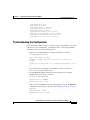
Changing Default Configurations 7-2
Validating the Configuration 7-4
Troubleshooting the Configuration 7-5
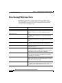
Fine-Tuning FXS Voice Ports 7-6
Activating the Voice Port 7-8
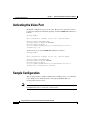
Sample Configuration 7-8
Cisco 2600 Sample Configuration 7-10
FXS Module Sample Configuration 7-10
Displaying Cisco 2600 Configuration Values 7-11
Displaying FXS Module Configuration Values 7-12
CHAPTER
8
Configuring Survivable Remote Site Telephony 8-1
Overview of Survivable Remote Site Telephony 8-2
Restrictions 8-2
Prerequisites 8-3
Supported Features 8-3
Fallback Behavior 8-4
Catalyst 4224 Access Gateway Switch Software Configuration Guide
x
OL-2031-02
Contents
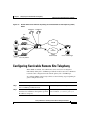
Configuring Survivable Remote Site Telephony 8-7
Verifying Survivable Remote Site Telephony 8-9
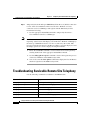
Troubleshooting Survivable Remote Site Telephony 8-10
Monitoring and Maintaining Survivable Remote Site Telephony 8-11
SRST Configuration Example 8-12
CHAPTER
9
Implementing Fax over IP on Cisco Voice Gateways 9-1
Overview 9-2
Fax Pass-Through 9-2
Cisco Fax Relay 9-3
Supported Platforms and Features 9-4
CHAPTER
10
Traffic Shaping 10-1
About Traffic Shaping 10-2
Why Use Traffic Shaping? 10-2
Traffic Shaping and Rate of Transfer 10-3
Discard Eligible Bit 10-4
Differences Between Shaping Mechanisms 10-4
Traffic Shaping and Queueing 10-6
Generic Traffic Shaping 10-6
How It Works 10-6
Configuration and Commands 10-7
Class-Based Traffic Shaping 10-8
How It Works 10-8
Configuration and Commands 10-8
Restrictions 10-9
Catalyst 4224 Access Gateway Switch Software Configuration Guide
OL-2031-02
xi
Contents
Frame Relay Traffic Shaping 10-9
How It Works 10-10
Derived Rates 10-10
Configuration and Commands 10-11
Restrictions 10-12
Distributed Traffic Shaping 10-12
Prerequisites 10-12
How It Works 10-12
Configuration 10-13
Restrictions 10-14
Low-Latency Queueing 10-14
CHAPTER
11
Configuring Encryption Services 11-1
Configuring the Encryption Service Adapter 11-2
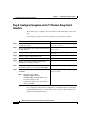
Step 1: Configure the T1 Channel Group 11-2
Step 2: Configure the Internet Key Exchange Security Protocol 11-3
Step 3: Configure IPSec Network Security 11-5
Step 4: Configure Encryption on the T1 Channel Group Serial Interface 11-8
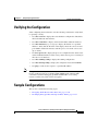
Verifying the Configuration 11-9
Sample Configurations 11-9
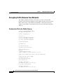
Encrypting Traffic Between Two Networks 11-10
Configuration File for the Public Gateway 11-10
Configuration File for the Private Gateway 11-11
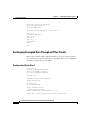
Exchanging Encrypted Data Through an IPSec Tunnel 11-14
Configuration File for Peer 1 11-14
Configuration File for Peer 2 11-16
Catalyst 4224 Access Gateway Switch Software Configuration Guide
xii
OL-2031-02
Contents
CHAPTER
12
Configuring Other Routing Protocols 12-1
Novell IPX 12-1
The Cisco Implementation of Novell IPX 12-1
IPX MIB Support 12-2
IPX Enhanced IGRP Support 12-2
LAN Support 12-3
VLAN Support 12-3
Multilayer Switching Support 12-3
IPX Configuration 12-3
IBM SNA 12-4
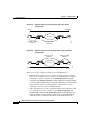
The Cisco Four-Phase Model for SNA-to-IP Integration 12-4
Phase One: SNA Centric 12-6
Phase Two: IP Transport 12-7
Phase Three: IP Client 12-8
Phase Four: IP Centric 12-9
Summary of Four-Phase Model 12-9
Scenarios for SNA-to-IP Integration 12-10
Line Consolidation 12-10
FEP Replacement 12-10
Desktop Consolidation 12-11
SNA Configuration 12-12
APPENDIX
A
Command Reference for Voice VLAN A-1
interface range A-1
Syntax A-1
Syntax Description A-2
Defaults A-2
Command Modes A-2
Usage Guidelines A-2
Example A-2
Catalyst 4224 Access Gateway Switch Software Configuration Guide
OL-2031-02
xiii
Contents
interface vlan A-3
Syntax A-3
Syntax Description A-3
Defaults A-3
Command Modes A-3
Usage Guidelines A-3
Example A-4
monitor session A-4
Syntax A-4
Syntax Description A-4
Defaults A-4
Command Modes A-5
Usage Guidelines A-5
Examples A-5
spanning-tree A-6
Syntax A-6
Syntax Description A-6
Defaults A-6
Command Modes A-6
Usage Guidelines A-6
Example A-7
spanning-tree portfast A-7
Syntax A-7
Syntax Description A-7
Defaults A-8
Command Modes A-8
Usage Guidelines A-8
Example A-8
Catalyst 4224 Access Gateway Switch Software Configuration Guide
xiv
OL-2031-02
Contents
switchport access A-8
Syntax A-9
Syntax Description A-9
Defaults A-9
Command Modes A-9
Usage Guidelines A-9
Example A-9
switchport voice vlan A-10
Syntax A-10
Syntax Description A-10
Defaults A-11
Command Modes A-11
Usage Guidelines A-11
Example A-11
APPENDIX
B
Synopsis of Basic VoIP Concepts B-1
VoIP Overview B-1
A Voice Primer B-2
How VoIP Processes a Typical Telephone Call B-2
Numbering Scheme B-3
Analog Versus Digital B-3
codecs B-4
Mean Opinion Score B-4
Delay B-5
Jitter B-6
End-to-End Delay B-7
Echo B-7
Signaling B-7
Catalyst 4224 Access Gateway Switch Software Configuration Guide
OL-2031-02
xv
Contents
APPENDIX
C
VoIP Configuration Examples C-1
FXS-to-FXS Connection Using RSVP C-1
Configuration for Catalyst 4224 RLB-1 C-3
Configuration for Catalyst 4224 RLB-w C-4
Configuration for Catalyst 4224 RLB-e C-5
Configuration for Catalyst 4224 RLB-2 C-6
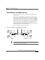
Linking PBX Users with E&M Trunk Lines C-7
Router San Jose Configuration C-8
Router Salt Lake City Configuration C-9
FXO Gateway to PSTN C-10
Router San Jose Configuration C-11
Router Salt Lake City Configuration C-11
FXO Gateway to PSTN (PLAR Mode) C-12
Router San Jose Configuration C-13
Router Salt Lake City Configuration C-13
INDEX
Catalyst 4224 Access Gateway Switch Software Configuration Guide
xvi
OL-2031-02
Preface
This preface contains these sections:
•
Objectives, page xvii
•
Audience, page xviii
•
Organization, page xviii
•
Related Documentation, page xix
•
Conventions, page xx
•
Obtaining Documentation, page xxi
•
Obtaining Technical Assistance, page xxiii
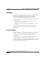
Objectives
This guide explains how to configure basic commands and scenarios for Ethernet
switching, IP WAN routing, Voice over IP (VoIP), and IP telephony on the
Catalyst 4224 Access Gateway Switch. To use this document effectively, you
need to be an experienced data networking professional with a background in
telecommunications.
Catalyst 4224 Access Gateway Switch Software Configuration Guide
OL-2031-02
xvii
Preface
Audience
Audience
This guide is intended for network administrators, engineers, and managers who
need to understand the Catalyst 4224 system or configure the software. It is also
intended for Cisco customer service representatives and system engineers.
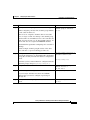
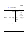
Organization
This guide contains the following chapters:
Title
Description
Chapter 1
Product Overview
Provides an overview of the
Catalyst 4224 Access Gateway
Switch software features.
Chapter 2
Configuring for the First
Time
Describes the initial steps of
configuring the Catalyst 4224.
Chapter 3
Configuring Ethernet
Switching
Describes how to configure the
Ethernet ports and voice VLANs.
Chapter 4
Configuring the Data
Interfaces
Describes how to configure the data
interfaces for IP WAN routing.
Chapter 5
Configuring the Voice
Interfaces
Describes how to configure key
voice interfaces.
Chapter 6
Configuring VoIP
Provides comprehensive
information on Cisco VoIP
configuration.
Chapter 7
Configuring the
Eight-Port FXS RJ-21
Module
Describes how to configure the
8-Port FXS Module.
Chapter 8
Configuring Survivable
Remote Site Telephony
Describes how to configure
survivable remote site telephony.
Chapter 9
Implementing Fax over
IP on Cisco Voice
Gateways
Provides an overview and
configuration information for fax
over IP technologies supported on
Cisco voice gateways.
Catalyst 4224 Access Gateway Switch Software Configuration Guide
xviii
OL-2031-02
Preface
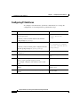
Related Documentation
Title
Description
Chapter 10
Traffic Shaping
Describes different types of traffic
shaping and provides pointers to
configuration and command
information.
Chapter 11
Configuring Encryption
Services
Describes how to configure
encryption services.
Chapter 12
Configuring Other
Routing Protocols
Describes how to configure the
Novell Internetwork Packet
Exchange (IPX) and IBM Systems
Network Architecture (SNA)
routing protocols.
Appendix A Command Reference for
Voice VLAN
Describes the key voice VLAN
commands used on Catalyst 4224.
Appendix B Synopsis of Basic VoIP
Concepts
Describes some basic VoIP
concepts.
Appendix C VoIP Configuration
Examples
Provides examples of VoIP
configurations.
Related Documentation
The following publications are available for the Catalyst 4224 Access Gateway
Switch:
•
Catalyst 4224 Access Gateway Switch Hardware Installation Guide
•
Cisco IOS configuration guides and command references—Use these
publications to help you configure the Cisco IOS software.
•
For information about MIBs, refer to the following URL:
http://www.cisco.com/public/sw-center/netmgmt/cmtk/mibs.shtml
Catalyst 4224 Access Gateway Switch Software Configuration Guide
OL-2031-02
xix
Preface
Conventions
Conventions
This guide uses the following conventions:
Convention
Description
boldface font
Commands and keywords are in boldface.
italic font
Arguments for which you supply values are in italics.
[ ]
Elements in square brackets are optional.
{x|y|z}
Alternative keywords are grouped in braces and
separated by vertical bars.
[x|y|z]
Optional alternative keywords are grouped in brackets
and separated by vertical bars.
string
A nonquoted set of characters. Do not use quotation
marks around the string or the string will include the
quotation marks.
screen
font
boldface screen
Terminal sessions and information the system displays
are in screen font.
Information you must enter is in boldface
screen
font.
font
italic screen font
Arguments for which you supply values are in italic
screen font.
This pointer highlights an important line of text
in an example.
Note
^
The symbol ^ represents the key labeled Control—for
example, the key combination ^D in a screen display
means hold down the Control key while you press the
D key.
< >
Nonprinting characters, such as passwords are in angle
brackets.
Means reader take note. Notes contain helpful suggestions or references to
material not covered in the publication.
Catalyst 4224 Access Gateway Switch Software Configuration Guide
xx
OL-2031-02
Preface
Obtaining Documentation
Caution
Means reader be careful. In this situation, you might do something that could
result in equipment damage or loss of data.
Obtaining Documentation
Cisco provides several ways to obtain documentation, technical assistance, and
other technical resources. These sections explain how to obtain technical
information from Cisco Systems.
Cisco.com
You can access the most current Cisco documentation on the World Wide Web at
this URL:
http://www.cisco.com/univercd/home/home.htm
You can access the Cisco website at this URL:
http://www.cisco.com
International Cisco websites can be accessed from this URL:
http://www.cisco.com/public/countries_languages.shtml
Documentation CD-ROM
Cisco documentation and additional literature are available in a Cisco
Documentation CD-ROM package, which may have shipped with your product.
The Documentation CD-ROM is updated monthly and may be more current than
printed documentation. The CD-ROM package is available as a single unit or
through an annual subscription.
Registered Cisco.com users can order the Documentation CD-ROM (product
number DOC-CONDOCCD=) through the online Subscription Store:
http://www.cisco.com/go/subscription
Catalyst 4224 Access Gateway Switch Software Configuration Guide
OL-2031-02
xxi
Preface
Obtaining Documentation
Ordering Documentation
You can find instructions for ordering documentation at this URL:
http://www.cisco.com/univercd/cc/td/doc/es_inpck/pdi.htm
You can order Cisco documentation in these ways:
•
Registered Cisco.com users (Cisco direct customers) can order Cisco product
documentation from the Networking Products MarketPlace:
http://www.cisco.com/en/US/partner/ordering/index.shtml
•
Registered Cisco.com users can order the Documentation CD-ROM
(Customer Order Number DOC-CONDOCCD=) through the online
Subscription Store:
http://www.cisco.com/go/subscription
•
Nonregistered Cisco.com users can order documentation through a local
account representative by calling Cisco Systems Corporate Headquarters
(California, U.S.A.) at 408 526-7208 or, elsewhere in North America, by
calling 800 553-NETS (6387).
Documentation Feedback
You can submit comments electronically on Cisco.com. On the Cisco
Documentation home page, click Feedback at the top of the page.
You can e-mail your comments to [email protected].
You can submit your comments by mail by using the response card behind the
front cover of your document or by writing to the following address:
Cisco Systems
Attn: Customer Document Ordering
170 West Tasman Drive
San Jose, CA 95134-9883
We appreciate your comments.
Catalyst 4224 Access Gateway Switch Software Configuration Guide
xxii
OL-2031-02
Preface
Obtaining Technical Assistance
Obtaining Technical Assistance
Cisco provides Cisco.com, which includes the Cisco Technical Assistance Center
(TAC) Website, as a starting point for all technical assistance. Customers and
partners can obtain online documentation, troubleshooting tips, and sample
configurations from the Cisco TAC website. Cisco.com registered users have
complete access to the technical support resources on the Cisco TAC website,
including TAC tools and utilities.
Cisco.com
Cisco.com offers a suite of interactive, networked services that let you access
Cisco information, networking solutions, services, programs, and resources at any
time, from anywhere in the world.
Cisco.com provides a broad range of features and services to help you with these
tasks:
•
Streamline business processes and improve productivity
•
Resolve technical issues with online support
•
Download and test software packages
•
Order Cisco learning materials and merchandise
•
Register for online skill assessment, training, and certification programs
To obtain customized information and service, you can self-register on Cisco.com
at this URL:
http://www.cisco.com
Technical Assistance Center
The Cisco TAC is available to all customers who need technical assistance with
a Cisco product, technology, or solution. Two levels of support are available: the
Cisco TAC website and the Cisco TAC Escalation Center. The avenue of support
that you choose depends on the priority of the problem and the conditions stated
in service contracts, when applicable.
Catalyst 4224 Access Gateway Switch Software Configuration Guide
OL-2031-02
xxiii
Preface
Obtaining Technical Assistance
We categorize Cisco TAC inquiries according to urgency:
•
Priority level 4 (P4)—You need information or assistance concerning Cisco
product capabilities, product installation, or basic product configuration.
•
Priority level 3 (P3)—Your network performance is degraded. Network
functionality is noticeably impaired, but most business operations continue.
•
Priority level 2 (P2)—Your production network is severely degraded,
affecting significant aspects of business operations. No workaround is
available.
•
Priority level 1 (P1)—Your production network is down, and a critical impact
to business operations will occur if service is not restored quickly. No
workaround is available.
Cisco TAC Website
You can use the Cisco TAC website to resolve P3 and P4 issues yourself, saving
both cost and time. The site provides around-the-clock access to online tools,
knowledge bases, and software. To access the Cisco TAC website, go to this
URL:
http://www.cisco.com/tac
All customers, partners, and resellers who have a valid Cisco service contract
have complete access to the technical support resources on the Cisco TAC
website. Some services on the Cisco TAC website require a Cisco.com login ID
and password. If you have a valid service contract but do not have a login ID or
password, go to this URL to register:
http://tools.cisco.com/RPF/register/register.do
If you are a Cisco.com registered user, and you cannot resolve your technical
issues by using the Cisco TAC website, you can open a case online at this URL:
http://www.cisco.com/en/US/support/index.html
If you have Internet access, we recommend that you open P3 and P4 cases through
the Cisco TAC website so that you can describe the situation in your own words
and attach any necessary files.
Catalyst 4224 Access Gateway Switch Software Configuration Guide
xxiv
OL-2031-02
Preface
Obtaining Additional Publications and Information
Cisco TAC Escalation Center
The Cisco TAC Escalation Center addresses priority level 1 or priority level 2
issues. These classifications are assigned when severe network degradation
significantly impacts business operations. When you contact the TAC Escalation
Center with a P1 or P2 problem, a Cisco TAC engineer automatically opens a
case.
To obtain a directory of toll-free Cisco TAC telephone numbers for your country,
go to this URL:
http://www.cisco.com/warp/public/687/Directory/DirTAC.shtml
Before calling, please check with your network operations center to determine the
level of Cisco support services to which your company is entitled: for example,
SMARTnet, SMARTnet Onsite, or Network Supported Accounts (NSA). When
you call the center, please have available your service agreement number and your
product serial number.
Obtaining Additional Publications and Information
Information about Cisco products, technologies, and network solutions is
available from various online and printed sources.
•
The Cisco Product Catalog describes the networking products offered by
Cisco Systems as well as ordering and customer support services. Access the
Cisco Product Catalog at this URL:
http://www.cisco.com/en/US/products/products_catalog_links_launch.html
•
Cisco Press publishes a wide range of networking publications. Cisco
suggests these titles for new and experienced users: Internetworking Terms
and Acronyms Dictionary, Internetworking Technology Handbook,
Internetworking Troubleshooting Guide, and the Internetworking Design
Guide. For current Cisco Press titles and other information, go to Cisco Press
online at this URL:
http://www.ciscopress.com
Catalyst 4224 Access Gateway Switch Software Configuration Guide
OL-2031-02
xxv
Preface
Obtaining Additional Publications and Information
•
Packet magazine is the Cisco monthly periodical that provides industry
professionals with the latest information about the field of networking. You
can access Packet magazine at this URL:
http://www.cisco.com/en/US/about/ac123/ac114/about_cisco_packet_maga
zine.html
•
iQ Magazine is the Cisco monthly periodical that provides business leaders
and decision makers with the latest information about the networking
industry. You can access iQ Magazine at this URL:
http://business.cisco.com/prod/tree.taf%3fasset_id=44699&public_view=tru
e&kbns=1.html
•
Internet Protocol Journal is a quarterly journal published by Cisco Systems
for engineering professionals involved in the design, development, and
operation of public and private internets and intranets. You can access the
Internet Protocol Journal at this URL:
http://www.cisco.com/en/US/about/ac123/ac147/about_cisco_the_internet_
protocol_journal.html
•
Training—Cisco offers world-class networking training, with current
offerings in network training listed at this URL:
http://www.cisco.com/en/US/learning/le31/learning_recommended_training
_list.html
Catalyst 4224 Access Gateway Switch Software Configuration Guide
xxvi
OL-2031-02
C H A P T E R
1
Product Overview
The Cisco Catalyst 4224 Access Gateway Switch (Catalyst 4224) is an integrated
switch/router that provides Voice-over-IP (VoIP) gateway and IP telephony
services to a small branch office. This section provides an overview of the
Catalyst 4224.
This section contains the following topics:
•
Features, page 1-2
•
Solution, page 1-3
•
IP Telephony, page 1-5
•
VoIP Gateway, page 1-6
•
IP Routing and WAN Features, page 1-7
•
Application Notes, page 1-10
•
Configuration Guidelines, page 1-18
•
Recommended Configurations, page 1-22
For a synopsis of basic VoIP concepts, see the following section in this manual:
Appendix B, “Synopsis of Basic VoIP Concepts”
For Voice-over-IP (VoIP) configuration examples, see the following section in
this manual:
Appendix C, “VoIP Configuration Examples”
Catalyst 4224 Access Gateway Switch Software Configuration Guide
OL-2031-02
1-1
Chapter 1
Product Overview
Features
Features
The Catalyst 4224 supports the following features:
•
24 10/100 Ethernet ports with inline power and quality of service (QoS) that
connect IP telephony phones and PCs
•
An integrated eight-port Foreign Exchange Station (FXS) module that
connects analog phones, fax machines, modems, key telephone systems
(KTS) or voicemail systems for VoIP
•
Three modular slots that support up to six ports on a wide variety of cards and
can provide connectivity to the public switched telephone network (PSTN) or
wide-area network (WAN)
– Multiflex Voice/WAN Interface Card (VWIC)
– Voice interface card (VIC)
– WAN interface card (WIC)
•
Onboard hardware-based encryption accelerator
Note
These cards can be shared with the Cisco 1600 series,
Cisco 1700 series, Cisco 2600 series, and Cisco 3600 series
platforms.
The Catalyst 4224 supports Cisco IOS software feature sets from the
Cisco IOS Release 12.1.4T. The following Cisco IOS images are available:
•
IP Plus (standard)
•
IP Plus with Firewall
•
IP Plus with IPsec 56
•
IP Plus with 3DES
•
IP Plus with Firewall and IPsec 56
•
IP Plus with Firewall and 3DES
•
Optional feature license required to use SRST
Catalyst 4224 Access Gateway Switch Software Configuration Guide
1-2
OL-2031-02
Chapter 1
Product Overview
Solution
Solution
The Catalyst 4224 can be deployed as part of a centralized call processing
network with a Cisco CallManager and Survivable Remote Site Telephony
(SRST) software that provides Ethernet switching, IP routing, VoIP gateway, and
IP telephony services for a small branch office.
Centralized call processing allows network administrators to deploy and manage
IP telephony applications at the corporate headquarters or the corporate data
center. Deploying and managing key systems or PBXs in branch offices is no
longer necessary. Centralized call processing provides remote branch office users
with access to IP telephony applications at centralized locations over the IP WAN.
Centralized call processing has the following benefits:
•
Centralized configuration and management
•
Remote access at to all Cisco CallManager features
•
IT staff not required at each remote site
•
Ability to rapidly deploy applications for remote users
•
Easy upgrades and maintenance
•
Lower total cost of ownership (TCO)
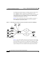
Figure 1-1 shows the Catalyst 4224 at a remote site with a centrally deployed
Cisco CallManager at corporate headquarters.
Catalyst 4224 Access Gateway Switch Software Configuration Guide
OL-2031-02
1-3
Chapter 1
Product Overview
Solution
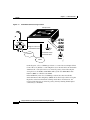
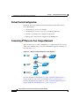
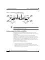
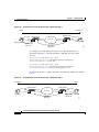
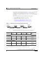
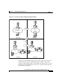
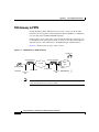
Figure 1-1
Centralized Call Processing Solution
Catalyst 4224
IP
A
C
VIC/WIC
ISDN BU
MFT-T1
IP
IP
Single T-1 access to
each branch office
IP
V
IP WAN
12 Channels voice/
12 Channels data
PSTN
55335
B
In the diagram, a Cisco CallManager cluster at a central site uses Simple Client
Control Protocol (SCCP) to control IP phones at two branch offices. In the branch
VoIP network, a Catalyst 4224 acts as an H.323 gateway, interconnecting the
analog devices, the PSTN, and IP WAN. This system uses ISDN Basic Rate
Interface (BRI) as a lifeline to the PSTN.
If the WAN link (or the Cisco CallManager cluster) becomes unavailable,
Survivable Remote Site Telephony (SRST) allows the Catalyst 4224 to keep the
IP phones on the branch networks running. Under these circumstances, the
Catalyst 4224 functions as an H.323 gateway, thereby ensuring uninterrupted
connectivity to the PSTN.
Catalyst 4224 Access Gateway Switch Software Configuration Guide
1-4
OL-2031-02
Chapter 1
Product Overview
IP Telephony
IP Telephony
The term IP telephony identifies a networking solution that integrates a switched
LAN, the Cisco CallManager, and IP phones.
The Catalyst 4224 is designed to work as part of a centralized Cisco CallManager
network that supports up to 24 remote users. As part of an IP telephony solution,
the Catalyst 4224 provides:
Note
•
24 ports of switched 10/100 Ethernet connectivity to PCs and servers on a
LAN
•
Line-powered Ethernet for Cisco IP phones
•
Limited backup capability when Cisco CallManager is unavailable
The Catalyst 4224 has digital signal processors (DSPs) installed on the
motherboard but does not support a DSP farm. Transcoding and conferencing
services are supplied to the branch office by a central Cisco CallManager.
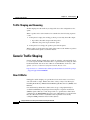
Ethernet Switching
Using the auxiliary VLAN feature, you can segment phones into separate logical
networks even though the data and voice infrastructure are physically the same.
The auxiliary VLAN feature places the phones into their own VLANs without the
need for end-user intervention. You can plug the phone into the switch, and the
switch provides the phone with the necessary VLAN information.
Key Ethernet switch features include:
•
Hardware-based Layer 2 switching
•
Software-based Layer 3 switching
•
Twenty-four 10BASE-T/100BASE-TX auto-sensing ports, each delivering
up to 200 Mbps of bandwidth or 100 Mbps of full-duplex bandwidth
•
Forwarding and filtering at full wire speed on each port
•
Port security that restricts a port to a user-defined group of stations
•
Support for up to 8000 unicast and more than 242 multicast addresses
Catalyst 4224 Access Gateway Switch Software Configuration Guide
OL-2031-02
1-5
Chapter 1
Product Overview
VoIP Gateway
•
Protocol Independent Multicast (PIM) and Internet Group Management
Protocol (IGMP) snooping
•
Per-port broadcast, multicast, and unicast storm control that prevents faulty
end stations from degrading overall system performance
•
Inline 48-volt DC power
•
MAC-based port-level security to prevent unauthorized stations from
accessing the switch
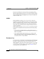
Survivable Remote Site Telephony
As enterprises extend IP telephony from central sites to remote offices, it is
important to provide backup redundancy at the remote branch office. The
Survivable Remote Site Telephony (SRST) software feature on the Catalyst 4224
automatically detects a failure in the network and uses Cisco Simple Network
Automated Provisioning (SNAP) to provide call-processing backup for the IP
phones in the remote office.
The Catalyst 4224 provides call processing for the duration of the failure and
ensures that the phones remain operational. Upon restoration of the WAN and
connectivity to the network, the system automatically shifts call-processing
functions to the primary Cisco CallManager cluster. Configuration for this
capability is done only once in the Cisco CallManager at the central site.
VoIP Gateway
Voice Over IP (VoIP) receives voice traffic at one location, converts it to TCP/IP
packets for the benefits of toll-bypass, and transports the packets across the WAN
to their destination.
To facilitate the migration to VoIP, the Catalyst 4224 includes an integrated
high-density eight-port FXS module. These FXS ports can connect analog
phones, modems, and fax machines to the Catalyst 4224.
The Catalyst 4224 supports a wide range of voice interface cards with the most
popular signaling protocols. Supported protocols and interface types include
T1-PRI, E1-PRI, T1-CAS, E1-CAS R2, ISDN BRI, and FXO.
Catalyst 4224 Access Gateway Switch Software Configuration Guide
1-6
OL-2031-02
Chapter 1
Product Overview
IP Routing and WAN Features
Table 1-1 describes the voice interface cards supported by the Catalyst 4224.
Table 1-1
Voice Interface Cards
Module
Description
VIC-2FXS
Two-port FXS voice/fax interface card
VIC-2FXO
Two-port FXO voice/fax interface card (North
American version)
VIC-2FXO-EU
Two-port FXO voice/fax interface card (European
version)
VIC-2BRI-S/T-TE
Two-port BRI S/T terminal equipment voice/fax
interface card (also supports data)
VWIC-1MFT-T1
One-port T1/Fractional T1 Multiflex Trunk with
CSU/DSU
VWIC-2MFT-T1
Dual-port T1/Fractional T1 Multiflex Trunk with
CSU/DSU
VWIC-1MFT-E1
One-port E1/Fractional E1 Multiflex Trunk with DSU
VWIC-2MFT-E1
Dual-port E1/Fractional E1 Multiflex Trunk with DSU
Additional VoIP gateway benefits include:
•
Private branch exchange (PBX) and PSTN connectivity
•
H.323v2 VoIP gateway functions
•
Onboard DSPs allocated to voice interfaces
•
Fax pass-through and Fax relay
•
Modem pass-through
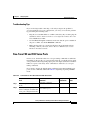
IP Routing and WAN Features
The Catalyst 4224 supports the following WAN features:
•
Multilink Point-to-Point Protocol (MLPPP)
•
Frame relay
Catalyst 4224 Access Gateway Switch Software Configuration Guide
OL-2031-02
1-7
Chapter 1
Product Overview
IP Routing and WAN Features
•
Asynchronous start-stop on ASCII
•
Synchronous PPP
The Catalyst 4224 supports the following IP routing features:
•
A high-performance MPC8260 processor running at 200 MHz provides the
processing power required for delivering voice, streaming video, and data to
the branch office
•
Packet-processing capabilities of 35,000 pps at 64-byte Layer 3
•
Onboard hardware encryption provides up to 10 times the performance of
software-only encryption by offloading the processing from the routing CPU
•
Modular WIC interfaces that can be shared with the Cisco 1600 series,
Cisco 1700 series, Cisco 2600 series, and Cisco 3600 series platforms
Table 1-2 describes the data interface cards supported by the Catalyst 4224.
Table 1-2
Data Interface Cards
Module
Description
VWIC-1MFT-T1
One-port T1/Fractional T1Multiflex Trunk with
CSU/DSU
VWIC-2MFT-T1
Dual-port T1/Fractional T1 Multiflex Trunk with
CSU/DSU
VWIC-1MFT-E1
One-port E1/Fractional E1 Multiflex Trunk with DSU
VWIC-2MFT-E1
Dual-port E1/Fractional E1 Multiflex Trunk with DSU
WIC-1DSU-T1
T1/Fractional T1 CSU/DSU
WIC-1DSU-56K4
One-port four-wire 56/64 Kbps CSU/DSU
WIC-1T
One-port high-speed serial
WIC-2T
Dual-port high-speed serial
WIC-2A/S
Dual-port async/sync serial
Catalyst 4224 Access Gateway Switch Software Configuration Guide
1-8
OL-2031-02
Chapter 1
Product Overview
IP Routing and WAN Features
Quality of Service
The Catalyst 4224 provides the performance and intelligent services of Cisco IOS
software for branch office applications. The Catalyst 4224 can identify user
applications—such as voice or multicast video—and classify traffic with the
appropriate priority levels. Quality of service (QoS) policies are enforced using
Layer 2 and 3 information such as 802.1p and IP precedence. The Catalyst 4224
queues use weighted random early detection (WRED), weighted round-robin
(WRR), and type-of-service/class-of-service (ToS/CoS) mapping to ensure that
QoS is maintained as packets traverse the network.
To ease the deployment of QoS, the Catalyst 4224 supports Cisco QoS Policy
Manager (QPM). QPM is a complete policy management tool that enables
provisioning of end-to-end differentiated services across network infrastructures
with converged voice, video, and data applications. The combination of QPM and
CiscoWorks Service Management Solution enables network administrators to
adjust service levels in accordance with defined QoS policies. The end result is
network-wide intelligent and consistent QoS that enables performance protection
for voice applications while reducing costs for growing networks.
VPN and Firewall Features
The Catalyst 4224 provides the same security to voice and video networks that is
available for data networks. The Catalyst 4224 supports the optional Cisco IOS
Software Firewall Feature Set, IP Security (IPsec) with data encryption standard
(DES), and Triple DES (3DES). Hardware encryption using the onboard
encryption accelerator provides higher performance than software-based
encryption, and frees processor capacity for other services.
The Catalyst 4224 supports the following encryption features:
•
56-bit DES encryption using Cipher Block Chaining (CBC) mode
•
168-bit 3DES encryption using CBC mode
•
MD5 and SHA-1 hashing, including support for the HMAC transform with
IPsec AH and ESP
•
Support for Dif-fie-Hellman key exchange
•
RSA and DSA public key signature and verification (when implemented by
IOS IPsec Crypto Engine)
Catalyst 4224 Access Gateway Switch Software Configuration Guide
OL-2031-02
1-9
Chapter 1
Product Overview
Application Notes
Note
DES and 3DES software is controlled by U.S. export regulations on encryption
products. For additional details visit the following URL:
http://www.cisco.com/wwl/export/crypto/
Application Notes
This section contains the following topics:
•
Architecture, page 1-10
•
DSP Allocation, page 1-11
•
InterVLAN Routing, page 1-14
•
Quality of Service, page 1-14
•
Layer 2 QoS, page 1-14
•
Separate Voice and Data VLANs, page 1-15
•
Single Voice and Data VLAN with dot1p, page 1-15
•
Layer 3 QoS, page 1-16
•
WAN QoS Queuing and Scheduling, page 1-16
•
Summary of the Layer 3 WAN QoS Features, page 1-16
Architecture
The Catalyst 4224 consists of the following physical subsystems:
•
Time-division multiplexing (TDM) subsystem—Two VIC/WIC/VWIC slots,
one VIC slot, a built-in high-density FXS module, and a TDM switch
•
CPU subsystem—Supports routing functions and interfaces for the TDM and
switch subsystems
•
Switch subsystem—24 10/100 Ethernet port switch with QoS and interfaces
to the CPU and power subsystems
Catalyst 4224 Access Gateway Switch Software Configuration Guide
1-10
OL-2031-02
Chapter 1
Product Overview
Application Notes
•
DSP subsystem—Interfaces to the TDM subsystem and CPU subsystem for
converting voice streams to IP packets
•
Power subsystem—Provides power to the Catalyst 4224 and inline power to
the IP phones that connect to the 10/100 Ethernet ports
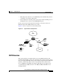
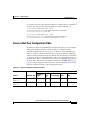
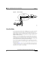
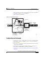
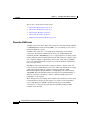
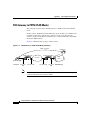
From a logical view, the Catalyst 4224 looks like a router that connects an
Ethernet switch and a TDM switch in one system.
Figure 1-2 shows a logical view of the Catalyst 4224.
Figure 1-2
Logical View of Catalyst 4224
IP
WAN
Router
Switch
TDM
POTS
IP
PC
Fax
Printer
PSTN
58705
IP phone
DSP Allocation
The Catalyst 4224 has six digital signal processors (DSPs) installed on the
motherboard. The DSPs convert voice signals into data packets and data packets
into voice signals. The DSPs on the Catalyst 4224 do not perform transcoding and
hardware conferencing. These services are performed at the central site by
Cisco CallManager. The DSPs only support VoIP. They do not support Voice
over Frame Relay (VoFR) and Voice over ATM (VoATM). The DSPs are not
field upgradeable.
Catalyst 4224 Access Gateway Switch Software Configuration Guide
OL-2031-02
1-11
Chapter 1
Product Overview
Application Notes
The DSPs compress and decompress packets based on codecs. The Catalyst 4224
supports the following codecs:
•
G.711 a-law 64 Kbps
•
G.711 mu-law 64 Kbps
•
G.729 abr 8 Annex-A & B 8 Kbps
•
G.729 ar8 G729 Annex-A 8 Kbps
•
G 729 r8 G729 8 Kbps
The number of DSP channels that you can use depends upon the VIC
configuration. The following rules apply when you allocate DSP channels for
T-1/E-1 VWICs:
Note
•
The eight-port FXS Module uses two of the six DSPs by default, leaving four
DSPs to configure for digital voice.
•
The maximum number of T1/E1 DS0s that you can configure is 24 on the six
available DSPs. The eight-port FXS module must be disabled using the CLI;
otherwise, only 16 channels are supported by four available DSPs.
•
Only use DSP channels if you configure voice DS0s.
•
Each set of four DS0s uses one DSP.
•
One entire DSP is used even if less than four DS0s are configured. Five DS0s
use two DSPs.
•
T1/E-1 DS0 channels cannot be used for analog channels.
You can disable the eight-Port FXS Module using the command line interface
(CLI), and thereby free up eight DSP channels for additional digital voice
channels.
The following rules apply when you allocate DSP channels for BRI, FXS, and
FXO VICs:
•
The two-Port BRI VIC uses two of the available four DS0 channels if you
configure voice. You can use the other two DS0s for voice FXS or FXO, but
not T-1/E-1.
Catalyst 4224 Access Gateway Switch Software Configuration Guide
1-12
OL-2031-02
Chapter 1
Product Overview
Application Notes
•
The two-Port FXS and FXO VIC uses two of the available four DSO
channels. The DSP is used when the VIC is plugged in, even if the ports are
not configured.
•
The eight-Port FXS Module uses eight DS0 channels or two DSPs, even if it
is not used (unless it is disabled using the CLI).
The following sample configuration shows DSP allocations:
C4224# sh voice dsp
BOOT
TYPE DSP CH CODEC
VERS STATE STATE
RST AI PORT
TS
==== === == ======== ==== ===== ======= === == ======= ==
5409 001 00
01
5409 002 00
01
02
03
5409 003 04
05
06
07
5409 004 00
01
02
03
5409 005 00
01
02
03
5409 006 00
01
02
03
{anlgHC}
{anlgHC}
{anlgMC}
{anlgMC}
{anlgMC}
{anlgMC}
{anlgMC}
{anlgMC}
{anlgMC}
{anlgMC}
{medium}
{medium}
{medium}
{medium}
{medium}
{medium}
{medium}
{medium}
{medium}
{medium}
{medium}
{medium}
.8
.8
.3
.3
.3
.3
.3
.3
.3
.3
3.5
.8
3.5
.8
3.5
.8
IDLE
IDLE
IDLE
IDLE
IDLE
IDLE
IDLE
IDLE
IDLE
IDLE
IDLE
IDLE
IDLE
IDLE
IDLE
IDLE
IDLE
IDLE
IDLE
IDLE
IDLE
IDLE
idle
idle
idle
idle
idle
idle
idle
idle
idle
idle
idle
idle
idle
idle
idle
idle
idle
idle
idle
idle
idle
idle
0
0
0
0
0
0
0
0
0
0
0
0
0
0
0
0
0
0
0
0
0
0
0
0
0
0
0
0
0
0
0
0
0
0
0
0
0
0
0
0
0
0
0
0
3/0
3/1
4/0
4/1
4/2
4/3
4/4
4/5
4/6
4/7
2/0:1
2/0:1
2/0:1
2/0:1
2/0:1
2/0:1
2/0:1
2/0:1
2/0:1
2/0:1
2/0:1
2/0:1
0
0
0
0
0
0
0
0
0
0
1
2
3
4
5
6
7
8
9
10
11
12
In the sample configuration, port 3/0 is an analog VIC that uses two of the four
channels in DSP 1. Slot 4 contains the eight-port FXS Module. This module takes
up two DSPs. DSP four, five, and six are being used for the 12 voice channels on
a MFT VWIC.
DSP resources are used for signaling and voice bearer channels. The signaling
channel is used for detecting off-hook/on-hook transitions.
Catalyst 4224 Access Gateway Switch Software Configuration Guide
OL-2031-02
1-13
Chapter 1
Product Overview
Application Notes
InterVLAN Routing
The forwarding performance for interVLAN routing on the Catalyst 4224 is
35 Kpps for 64-byte packets. Fast Switching is the default switching path. The
Catalyst 4224 supports Cisco Express Forwarding (CEF).
Quality of Service
The Catalyst 4224 can function as a Layer 2 switch connected to a Layer 3 router.
When a packet enters the Layer 2 engine directly from a switch port, it is placed
into one of four queues in the dynamic, 32-Mbyte shared memory buffer. The
queue assignment is based on the dot1p value in the packet. Any voice bearer
packets that come in from the IP phones on the voice VLAN are automatically
placed in the highest priority (Queue 3) based on the 802.1p value generated by
the IP phone. The queues are then serviced on a WRR basis. The control traffic,
which uses a CoS/ToS of 3, is placed in Queue 2.
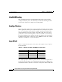
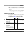
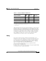
Layer 2 QoS
Table 1-3 summarizes the queues, CoS values, and weights for Layer 2 QoS on
the Catalyst 4224.
Table 1-3
Queues, CoS values, and Weights for Layer 2 QoS
Queue Number
CoS Value
Weight
3
5,6,7
255
2
3,4
64
1
2
16
0
0,1
1
The weights specify the number of packets that are serviced in the queue before
moving on to the next queue. Voice Real-Time Transport Protocol (RTP) bearer
traffic marked with a CoS /ToS of 5 and Voice Control plane traffic marked with
Catalyst 4224 Access Gateway Switch Software Configuration Guide
1-14
OL-2031-02
Chapter 1
Product Overview
Application Notes
a CoS/ToS of 3 are placed into the highest priority Queues. If the queue has no
packets to be serviced, it will be skipped. WRED is not supported on the Fast
Ethernet ports.
The WRR default values cannot be changed. There are currently no CLI
commands to determine QoS information for WRR weights and queue mappings.
You cannot configure port-based QoS on the Layer 2 switch ports.
Separate Voice and Data VLANs
To be consistent with Cisco IP Telephony QoS design recommendations, you
should configure separate voice and data VLANs. The following sample
configuration shows how to configure separate voice and data VLANs.
interface FastEthernet5/22
no ip address
duplex auto
speed auto
switchport access vlan 60
switchport voice vlan 160
snmp trap link-status
Packets arriving on the specified voice VLAN will automatically have the 802.1p
priority values read on ingress. Unlike the Catalyst 3500, trunking mode does not
have to be used to distinguish between a voice and a data VLAN on a single port.
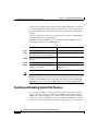
Single Voice and Data VLAN with dot1p
If the voice and data VLAN must be the same (a single subnet), using the dot1p
extension will enable the Catalyst 4224 to recognize the dot 1p CoS value from
the IP phone and place the packet in a queue based on the 802.1p value. The
following sample configuration shows how to configure a single voice and data
VLAN with dot1p.
interface FastEthernet5/23
no ip address
duplex auto
speed auto
switchport access vlan 160
switchport voice vlan dot1p
Catalyst 4224 Access Gateway Switch Software Configuration Guide
OL-2031-02
1-15
Chapter 1
Product Overview
Application Notes
Similar to other voice-enabled Catalyst platforms, the Catalyst 4224 learns that an
IP phone is attached to the port via the CDP message exchange.
Layer 3 QoS
You can configure QoS on the Layer 3 CPU from the CLI, which is very similar
to the interface on the Cisco 1750, Cisco 2600 series, and Cisco 3600 series
routers.
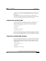
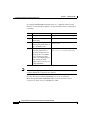
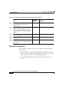
WAN QoS Queuing and Scheduling
The Catalyst 4224 supports WAN QoS queuing and scheduling. Table 1-4 shows
Catalyst 4224 WAN QoS queuing and scheduling features.
Table 1-4
Catalyst 4224 WAN QoS Queuing and Scheduling Features
Frame Relay
MLPPP
PPP
HDLC
No LLQ/CBWFQ No LLQ/CBWFQ LLQ/CBWFQ
LLQ/CBWFQ
IP RTP Priority
No IP RTP
Priority
IP RTP Priority
FRF.12
LFI
IP RTP Priority
with CBWFQ
The Service Policy command is disabled for Frame Relay.
Summary of the Layer 3 WAN QoS Features
In summary, the Catalyst 4224 supports the following Cisco IOS Layer 3 WAN
QoS features:
•
Classification and Marking
– Access control lists (ACL)
– Class-based marking
– Class-based matching
– Committed Access Rate (CAR)
Catalyst 4224 Access Gateway Switch Software Configuration Guide
1-16
OL-2031-02
Chapter 1
Product Overview
Application Notes
– Differentiated services code point (DSCP) marking
– IP Precedence
– L2 Marking
– L2 Matching
– Match RTP
– Network-based Application Recognition (NBAR)
– Policy-based Routing (PBR)
– QoS Preclassification for tunnels
•
Congestion Avoidance:
– Flow-based RED (FRED)
– Weighted RED (WRED)
– WRED with DSCP
•
Policing and Traffic Shaping:
– Class-based policing
– Class-based shaping
– IP Precedence
– Frame Relay Traffic Shaping (FRTS)
– General Traffic Shaping (GTS)
•
Link Efficiency:
– cRTP fast/CEF-switching
– FR LFI (FRF.12)
– MLPPP/LFI
– RTP Header Compression (cRTP)
Catalyst 4224 Access Gateway Switch Software Configuration Guide
OL-2031-02
1-17
Chapter 1
Product Overview
Configuration Guidelines
Configuration Guidelines
This section provides platform specific guidelines for configuring the
Catalyst 4224.
This section contains the following topics:
•
Default Port Configuration, page 1-18
•
Separate VLAN for Voice and Data, page 1-19
•
Port Configuration for a Single Subnet, page 1-19
•
InterVLAN and WAN Routing Configuration, page 1-20
•
Centralized Cisco CallManager and DHCP Server, page 1-20
•
Voice Port Configuration, page 1-21
•
Interface Range Command Support, page 1-22
•
Switched Port Analyzer (SPAN), page 1-22
For Voice over IP (VoIP) configuration examples, see the following section in
this manual:
Appendix C, “VoIP Configuration Examples”
Default Port Configuration
The Catalyst 4224 boots up as a Layer 2 switch. The following sample
configuration shows a default port configuration.
C4224_SF# sh run int fas5/7
Building configuration...
Current configuration : 96 bytes
interface FastEthernet5/7
no ip address
duplex auto
speed auto
snmp trap link-status
end
Catalyst 4224 Access Gateway Switch Software Configuration Guide
1-18
OL-2031-02
Chapter 1
Product Overview
Configuration Guidelines
Separate VLAN for Voice and Data
Unlike the Catalyst 3500, you do not need to preconfigure VLANs with a VLAN
database command. To be consistent with Cisco IP Telephony QoS design
guidelines, you should configure a separate VLAN for voice and data. The
following example shows a recommended configuration.
interface FastEthernet5/22
no ip address
duplex auto
speed auto
switchport access vlan 60
switchport voice vlan 160
snmp trap link-status
spanning-tree portfast
This sample configuration instructs the IP phone to generate a packet with an
802.1q VLAN ID of 160 and an 802.1p value of 5 (default for voice bearer
traffic).
Note
Portfast is supported only on nontrunk ports.
Port Configuration for a Single Subnet
If you have only a single subnet available, use the same subnet for voice and data.
The following sample configuration shows a port configuration for a single
subnet.
interface FastEthernet5/23
no ip address
duplex auto
speed auto
switchport access vlan 160
switchport voice vlan dot1p
snmp trap link-status
spanning-tree portfast
This sample configuration instructs the IP phone to generate an 802.1 Q frame
with a null VLAN ID value and an 802.1p value (default is CoS of 5 for bearer
traffic). The voice VLAN and data VLAN are both 160 in this example.
Catalyst 4224 Access Gateway Switch Software Configuration Guide
OL-2031-02
1-19
Chapter 1
Product Overview
Configuration Guidelines
InterVLAN and WAN Routing Configuration
Configuring interVLAN routing on the Catalyst 4224 is identical to configuring
interVLAN routing on the Catalyst 6000 with an MSFC. Configuring an interface
for WAN routing is consistent with other Cisco IOS platforms. The following
sample shows a configuration for interVLAN routing.
interface Vlan 160
description Voice VLAN
ip address 10.6.1.1 255.255.255.0
interface Vlan 60
description Data VLAN
ip address 10.60.1.1 255.255.255.0
interface Serial1/0
ip address 160.3.1.2 255.255.255.0
The Catalyst 4224 supports standard IGP routing protocols such as RIP, Interior
Gateway Routing Protocol (IGRP), Enhanced Interior Gateway Routing Protocol
(EIGRP), and open shortest path first (OSPF). It also supports multicast routing
for PIM dense mode, sparse mode, and sparse-dense mode.
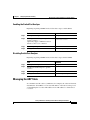
Centralized Cisco CallManager and DHCP Server
In a centralized Cisco CallManager deployment model, the DHCP server would
probably be located across the WAN link. You should include an ip helper
command on the voice VLAN interface that points to the DHCP server so that the
IP phone can obtain the IP address and the TFTP server address. The following
sample configuration shows a configuration for ip helper-address on the voice
VLAN:
interface Vlan 160
description Voice VLAN
ip address 10.6.1.1 255.255.255.0
ip helper-address 172.20.73.14
As an alternative, you could use the Cisco IOS DHCP server capabilities on the
Catalyst 4224. The following sample configuration shows a configuration for the
DHCP configuration options.
C4224_SF(config)# ip dhcp pool SF
C4224_SF(dhcp-config)# ?
Catalyst 4224 Access Gateway Switch Software Configuration Guide
1-20
OL-2031-02
Chapter 1
Product Overview
Configuration Guidelines
DHCP pool configuration commands:
client-identifier
Client identifier
client-name
Client name
default-router
Default routers
dns-server
DNS servers
domain-name
Domain name
hardware-address
Client hardware address
host
Client IP address and mask
option Raw DHCP options
C4224_SF(dhcp-config)# option 150 ip ?
Hostname or A.B.C.D
Note
Server's name or IP address
DHCP option 150 is supported locally. This local support provides the IP address
of the TFTP server, which has the IP phones’ configuration. An ip
helper-address would not be required in this case because the IP phone has its IP
address and the TFTP server address. The configuration request to the TFTP
server is a unicast packet.
Voice Port Configuration
You configure voice ports on the Catalyst 4224 as you would in standard
Cisco IOS software. The following sample configuration shows a configuration
for the eight-port FXS Module:
dial-peer voice 41 voip
destination-pattern 1...
session target ipv4:172.20.73.13
codec g711ulaw
!
dial-peer voice 1005 pots
destination-pattern 1005
port 4/0
Catalyst 4224 Access Gateway Switch Software Configuration Guide
OL-2031-02
1-21
Chapter 1
Product Overview
Recommended Configurations
Interface Range Command Support
You can use the range command. The following sample configuration shows how
to configure the range command:
C4224_SF(config)# int range fas5/2 - 5
switchport access vlan 60
switchport voice vlan 160
Switched Port Analyzer (SPAN)
Switched Port Analyzer (SPAN), also known as port monitoring, is supported for
up to two sessions. Spanning a VLAN is not supported. You can only span
selected interfaces. The following sample configuration shows a configuration for
setting a port monitor session with the range command:
C4224_SF(config)# monitor session 1 ?
destination SPAN destination interface or VLAN
source
SPAN source interface or VLAN
Recommended Configurations
This section contains the following topics:
•
No VTP or DTP Support, page 1-23
•
Creating a VLAN, page 1-23
•
Defining a VLAN on a Trunk Port, page 1-23
•
Trunking, page 1-24
•
Fractional PRI Configuration, page 1-24
•
No Ring Back Tone Generated, page 1-25
•
MTP Required on Cisco CallManager, page 1-26
•
H323-Gateway VOIP Bind SRCADDR Command, page 1-27
•
Port Fast Not Enabled on Trunk Ports, page 1-28
•
Priority Queuing on Frame Relay, page 1-28
Catalyst 4224 Access Gateway Switch Software Configuration Guide
1-22
OL-2031-02
Chapter 1
Product Overview
Recommended Configurations
•
Maximum Number of VLAN and Multicast Groups, page 1-29
•
IP Multicast Support, page 1-29
No VTP or DTP Support
Using the interface switchport access or switchport trunk VLAN commands
automatically creates a voice VLAN and data VLAN. If you require an additional
VLAN beyond the voice and data VLAN when connecting to another switch, you
must add it manually using the VLAN database command from the EXEC prompt.
Creating a VLAN
The following sample configuration shows how to define a VLAN manually:
C4224(vlan)# vlan 10 name external_switch_Vlan10
VLAN 10 added:
Name: external_switch_Vlan10
C4224(vlan)#vlan 11 name external_switch_Vlan11
VLAN 11 added:
Name: external_switch_Vlan11
C4224(vlan)#exit
APPLY completed.
Exiting...
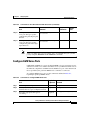
Defining a VLAN on a Trunk Port
The following sample configuration shows how to define a VLAN on a trunk port.
C4224(config-if)# switchport trunk allowed vlan 10
C4224(config-if)# switchport trunk allowed vlan add 11
By default, the trunk interface accepts all VLANs created by the VLAN database.
Therefore, you should use the switchport trunk allowed command to delete
unwanted VLANs from the interface.
Catalyst 4224 Access Gateway Switch Software Configuration Guide
OL-2031-02
1-23
Chapter 1
Product Overview
Recommended Configurations
Trunking
The Catalyst 4224 supports only dot1Q trunking. Dynamic Trunking Protocol
(DTP) is not supported. A Catalyst switch that is trunked to the Catalyst 4224
must have the trunking mode set to either On or No negotiate and type dot1q.
Fractional PRI Configuration
The maximum of 16 channels are available for trunk voice ports. This can cause
a problem when a PSTN or PBX uses an unavailable channel to send a call to the
Catalyst 4224. To prevent this type of problem, follow this procedure:
Step 1
Always configure the Primary Rate Interface (PRI) VIC last (after you configure
all the VIC cards that require the DSP resources).
Step 2
Allocate all 24 time slots for the PRI group. The following sample configuration
shows a configuration for the range command.
controller T1 1/0
framing esf
linecode b8zs
pri-group timeslots 1-24
Step 3
Note
The DSP resources are not sufficient for the 24 time slots. Therefore
you receive this message: insufficient DSP resources. Ignore this
message.
Note
You need to tell the switch or PBX to make the time slots
out-of-service. If you do not allocate 24 time slots, a SERVICE
message is not sent for the unallocated time slots. This is an important
caveat.
Use the show voice dsp command to see how many channels are allocated with
the available DSP resources. In a test case, 16 time slots could be allocated DSP
resources.
Catalyst 4224 Access Gateway Switch Software Configuration Guide
1-24
OL-2031-02
Chapter 1
Product Overview
Recommended Configurations
Step 4
Busy-out the time slots for which DSP resources could not be allocated. The
following sample configuration shows how to busy-out the time slots:
isdn service dsl 0 b_channel 17-24 state 2
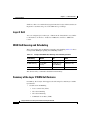
Step 5
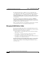
Use the show isdn service command to ensure that the channel is out-of-service.
The following sample configuration shows channels in service:
C4224# sh isdn ser
PRI Channel Statistics:
ISDN Se1/0:23, Channel [1-24]
Configured Isdn Interface (dsl) 0
Channel State (0=Idle 1=Proposed 2=Busy 3=Reserved 4=Restart
5=Maint_Pend)
Channel :
1 2 3 4 5 6 7 8 9 0 1 2 3 4 5 6 7 8 9 0 1 2 3 4
State
:
0 0 0 0 0 0 0 0 0 0 0 0 0 0 0 0 0 0 0 0 0 0 0 3
Service State (0=Inservice 1=Maint 2=Outofservice)
Channel : 1 2 3 4 5 6 7 8 9 0 1 2 3 4 5 6 7 8 9 0 1 2 3 4
State
:
0 0 0 0 0 0 0 0 0 0 0 0 0 0 0 0 2 2 2 2 2 2 2 2
For incoming calls, only time slots 1-16 are used by the switch or PBX. North
American CO ISDN switches should support SERVICE/SERVCE ACK messages
for maintenance service of B-channels on the PRI span. For the CO switches that
do not support this service, you must ask the provider to busy-out the channels.
No Ring Back Tone Generated
When receiving or placing a call from an ISDN terminal (T1/E1 PRI), there is no
Progress IE in the setup. (Progress IE = 0.) The Catalyst 4224 does not generate
ringback when it receives an alert from Cisco CallManager. You can avoid this
situation and force the Catalyst 4224 to generate a ringback using the progress
indicator commands on the VoIP and POTS dial-peer statements. The following
sample configuration shows how to generate a ringback.
dial-peer voice 500 voip
destination-pattern 5...
progress_ind setup enable 3
session target ipv4:10.200.73.15
codec g711ulaw
dial-peer voice 300 pots
destination-pattern 1...
Catalyst 4224 Access Gateway Switch Software Configuration Guide
OL-2031-02
1-25
Chapter 1
Product Overview
Recommended Configurations
progress_ind alert enable 8
port 3/1:23
forward-digits all
Note
alert enable 8 is a hidden command option, which you cannot find by using
the ? at the CLI.
The following sample configuration shows what happens when you try to find this
command option:
C4224-2(config-dial-peer)# progress_ind alert ?
% Unrecognized command
This ringback situation applies only to PRI. It does not apply to BRI.
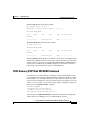
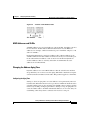
MTP Required on Cisco CallManager
Prior to support for H.323 Version 2, you needed to enable the MTP Required
checkbox. This checkbox is located in the Catalyst 4224 H.323 Gateway
Configuration page in Cisco CallManager to define an H.323 gateway. All
Cisco IOS H.323 gateways with Cisco IOS 12.07 or later now support H.323
Version 2. You should not ordinarily enable this checkbox box when defining the
Catalyst 4224 as an H.323 Gateway. The only time you should check the box is if
transcoding is used at the central site. Transcoding would be necessary in
situations where the Catalyst 4224 uses G.729 for IP WAN calls and a voice mail
system at the central site supports G.711 only.
If you enable MTP Required on the Catalyst 4224 H.323 Gateway, analog POTS
calls to an IP phone locally connected will traverse the IP WAN. The call between
the analog FXS POTS and the IP Phone is anchored at the central site transcoding
device. This is normal behavior for a Cisco IOS H.323 gateway when MTP
Required is enabled. This leads to performance that is not optimal. Therefore,
unless transcoding is required, Media Termination Point (MTP) should not be
enabled on the H.323 Gateway definition for Catalyst 4224. Another option
would be to use G.711 across the IP WAN.
The following sample configurations show how the VoIP endpoints can be
verified.
Catalyst 4224 Access Gateway Switch Software Configuration Guide
1-26
OL-2031-02
Chapter 1
Product Overview
Recommended Configurations
With the MTP Required checkbox enabled:
The Catalyst 4224 is 10.253.1.1
Transcoder is Catalyst 6000 at Central :
10.1.1.11
C4224_SF# sh ip sock
Proto
Remote
OutputIF
17 10.1.1.11
Port
Local
Port
16541 10.253.1.1
18757
In Out Stat TTY
0
0
1
0
With the MTP Required checkbox not enabled:
IP Phone is 10.6.1.4
C4224_SF# sh ip sock
Proto
Remote
OutputIF
17 10.6.1.4
Port
Local
Port
26287 10.253.1.1
17047
In Out Stat TTY
0
0
1
0
When the MTP Required checkbox is enabled, a call between a local IP phone and
an FXS analog POTS connected to the Catalyst 4224 is anchored at the transcoder
at the Central site, and local calls use WAN bandwidth. When the MTP Required
checkbox is not enabled, the local FXS-to-IP phone call is directly connected
between the Catalyst 4224 H.323 gateway and the IP phone.
H323-Gateway VOIP Bind SRCADDR Command
You must always use the following command to configure the IP address of the
gateway. This command ensures that the IP address included in the H.323 packet
is deterministic—it consistently indicates the same address for the source. If the
end point is non-deterministic, the call is anchored at the serial interface port and
silence or one-way audio occurs. The following sample configuration shows the
H323-gateway voip bind srcaddr command:
interface Loopback1
description h323 gateway address
ip address 10.253.1.1 255.255.255.0
h323-gateway voip bind srcaddr 10.253.1.1
You must place the h323 bind interface command on the interface with the IP
address that Cisco CallManager uses to define the H.323 gateway.
Catalyst 4224 Access Gateway Switch Software Configuration Guide
OL-2031-02
1-27
Chapter 1
Product Overview
Recommended Configurations
Port Fast Not Enabled on Trunk Ports
You should configure ports as switched access ports. However, there may be
implementations where your requirements dictate configuring ports as trunks and
you want to standardize this configuration across all 24 ports. This is not the
recommended configuration. Because of DHCP request timeouts on Windows
95/NT, portfast may be a desirable feature. However, portfast is not supported on
ports in trunking mode. To reduce the forwarding delay time of a port, use the
global configuration commands for the specific VLAN and reduce the forwarding
timers to the minimum value of four seconds. See the following sample
configuration:
spanning-tree portfast bpduguard
spanning-tree vlan 60 forward-time 4
spanning-tree vlan 160 forward-time 4
These commands configure VLAN ports to forward data in eight seconds.
If you connect Catalyst 4224 to another switch, make sure that the timers are the
same value. Otherwise Spanning Tree issues may arise. Also note that only
802.1Q trunking is supported on the Catalyst 4224.
Priority Queuing on Frame Relay
Frame relay does not support LLQ/CBWFQ. The service policy output command
is currently disabled. Therefore, only ip rtp priority is supported as a voice
priority queuing scheme. FRF.12 is supported on frame relay links.
The recommended configuration for FRF.12 and ip rtp priority is shown in the
following procedure. The parameter values are for illustrative purposes only.
Your values may differ.
Step 1
Define the appropriate map class. The following sample configuration shows how
to define the map class:
map-class frame-relay VOIP_256
no frame-relay adaptive-shaping
frame-relay cir 250000
frame-relay bc 1000
frame-relay be 0
frame-relay mincir 250000
frame-relay fair-queue
Catalyst 4224 Access Gateway Switch Software Configuration Guide
1-28
OL-2031-02
Chapter 1
Product Overview
Recommended Configurations
frame-relay fragment 320
frame-relay ip rtp priority 16384 16383 170
Step 2
Apply the map class to a frame relay sub interface. The following sample
configuration shows how to apply the map class:
interface Serial0/0.300 point-to-point
ip address 1.1.1.1
frame-relay interface-dlci 300
frame-relay class VOIP_256
Step 3
Apply frame relay shaping at the main interface. The following sample
configuration shows how to apply shaping:
interface ser0/0
encapsulation frame-relay
frame-relay traffic-shaping
Maximum Number of VLAN and Multicast Groups
The maximum number of VLANs multiplied by the number of multicast groups
must be less than or equal to 242. For example, the number for 10 VLANs and 20
groups would be 200, which is within the 242 limit.
IP Multicast Support
The maximum number of multicast groups is related to the maximum number of
VLANs. The product of the number of multicast groups and the number of
VLANs cannot exceed 242. Multicast support includes the following items:
•
Support for sparse mode, dense mode, and sparse-dense mode
•
IGMP snooping Versions 1, 2, and 3
Catalyst 4224 Access Gateway Switch Software Configuration Guide
OL-2031-02
1-29
Chapter 1
Product Overview
Recommended Configurations
Catalyst 4224 Access Gateway Switch Software Configuration Guide
1-30
OL-2031-02
C H A P T E R
2
Configuring for the First Time
This section describes the initial steps of configuring the Catalyst 4224 and
outlines the features of the Cisco IOS command line interface (CLI). Use this tool
when you configure Catalyst 4224 interfaces.
This section contains the following topics:
•
First-Time Configuration, page 2-1
•
Using the Cisco IOS CLI, page 2-5
First-Time Configuration
This section contains the following topics:
•
Booting the Catalyst 4224, page 2-2
•
Downloading an Image to Boot Flash Memory, page 2-2
•
Configuring the Management Port, page 2-3
•
Interface Numbering, page 2-4
Catalyst 4224 Access Gateway Switch Software Configuration Guide
OL-2031-02
2-1
Chapter 2
Configuring for the First Time
First-Time Configuration
Booting the Catalyst 4224
The factory configures the Catalyst 4224 to automatically load a Cisco IOS
image. The software configuration register in the Catalyst 4224 determines where
to find the image. The factory sets this register to load the Cisco IOS image into
boot flash memory from configuration register 0x0101. This register enables
autoboot at register 0x0103.
Table 2-1 shows the Catalyst 4224 default configuration.
Table 2-1
Catalyst 4224 Default Configuration
Feature
Default Value
Host name
Router
Interface configuration
None
VLAN configuration
None
Password encryption
Disabled
Break to console
Ignore
After booting the Catalyst 4224 for the first time, you can configure the interfaces
and then save the configuration to a file in NVRAM.
Downloading an Image to Boot Flash Memory
Note
Before you can download an image, you must first configure the management
port. See “Configuring the Management Port” section on page 2-3.
If you have already configured the Catalyst 4224, you can download a run-time
image from a TFTP server on the network. TFTP downloads can take place over
the Ethernet management port.
To download an image to boot flash memory, use privileged mode to enter the
following command:
copy tftp: [/directory] /filename [/directory] /filename
Catalyst 4224 Access Gateway Switch Software Configuration Guide
2-2
OL-2031-02
Chapter 2
Configuring for the First Time
First-Time Configuration
Connecting a Terminal
To connect a terminal to the console port using the cable and adapters provided
with the Catalyst 4224, connect to the port using the RJ-45-to-RJ-45 cable and
RJ-45-to-DB-25 DTE adapter or RJ-45-to-DB-9 DTE adapter (labeled Terminal).
Check the documentation that came with your terminal to determine the baud rate.
The baud rate of the terminal must match the default baud rate (9600 baud) of the
console port.
Set up the terminal as follows:
•
9600 baud
•
Eight data bits
•
No parity
•
Two stop bits
•
No flow control
Connecting a Modem
Connect the modem to the port using the RJ-45-to-RJ-45 cable and the
RJ-45-to-DB-25 DCE adapter (labeled Modem).
Configuring the Management Port
You can manage the Catalyst 4224 through the 10/100 management port by
assigning it an IP address.
Caution
By default, the Fast Ethernet interface does not route data traffic.
Cisco recommends that you do not override this default
configuration.
If the Ethernet 10/100 management port is up and an IP address has been
configured, the Catalyst 4224 selects the IP address assigned to the 10/100
Ethernet management port.
Catalyst 4224 Access Gateway Switch Software Configuration Guide
OL-2031-02
2-3
Chapter 2
Configuring for the First Time
First-Time Configuration
If the selected network management IP address is removed or the interface or
subinterface associated with this IP address is shut down, the Catalyst 4224
selects another IP address as a replacement.
If all the interfaces are down or no IP address has been assigned to any interface
or subinterface that is running, the IP address for network management is 0.0.0.0.
Interface Numbering
The Catalyst 4224 has three slots in which you can install interface cards:
•
Slot 1 supports voice interface cards (VICs), WAN interface cards (WICs),
and voice and WAN interface cards (VWICs).
•
Slot 2 supports VICs, WICs, and VWICs.
•
Slot 3 supports VICs and VWICs but does not support WICs.
•
Slot 4 supports an eight-Port FXS RJ21 Module.
•
Slot 5 supports 10/100 Ethernet switching ports.
Each individual interface is identified by a slot number and a port number. The
slots are numbered as follows:
•
Slot 0 supports the following interfaces embedded in the mainboard:
– Console port (con 0)
– Ethernet Management port (Fast Ethernet 0/0)
•
Note
Slot 1 ports are numbered from right to left (1/1 and 1/0).
On the WIC-2A/S, the top slot is 1 and the bottom slot is 0.
•
Slot 2 ports are numbered from right to left (2/1 and 2/0).
•
Slot 3 ports are numbered from right to left (3/0 and 3/1).
When you configure an interface, identify the interface name before the slot and
port numbers. For example, if you install a serial T1 VWIC interface in Slot 2,
port 0 would be labeled as serial 2/0.
Figure 2-1 shows the Catalyst 4224 front panel.
Catalyst 4224 Access Gateway Switch Software Configuration Guide
2-4
OL-2031-02
Chapter 2
Configuring for the First Time
Using the Cisco IOS CLI
Figure 2-1
Catalyst 4224 Front Panel
10/100 Ethernet (slot 5)
CATALYST 4224
1
2
3
4
5
6
7
8
9
10
11
12
13
14
15
16
17
18
19
20
21
22
23
24
CONSOLE
0
1
2
3
4
5
6
7
VIC 3
VWIC 2
VWIC 1
HDA
STATUS
STATUS
PS
RPS
ACCESS GATEWAY SWITCH
Status LED
Switch
utilization
VWIC
(slots 1 and 2)
10/100 Mgt port
55803
WS-U4604-8FXS
8-Port RJ21 FXS
(slot 4)
VIC
(slot 3)
Using the Cisco IOS CLI
Cisco voice gateways run versions of Cisco IOS software that includes
specialized adaptations for Voice over IP (VoIP) and Media Gateway Control
Protocol (MGCP). If you are familiar with other versions of Cisco IOS, you will
find configuring Cisco voice gateways straightforward because you will use the
Cisco IOS CLI, with which you are familiar.
If you have never used the Cisco IOS CLI, you should still be able to perform the
configuration required using the instructions and examples provided in this guide.
To help get you started, this section provides a brief overview of some of the main
features of the CLI. For further information, refer to the Cisco IOS configuration
guides and command references for details about specific commands.
This section contains the following topics:
•
Getting Help, page 2-6
•
Command Modes, page 2-6
•
Disabling a Command or Feature, page 2-8
•
Saving Configuration Changes, page 2-8
Catalyst 4224 Access Gateway Switch Software Configuration Guide
OL-2031-02
2-5
Chapter 2
Configuring for the First Time
Using the Cisco IOS CLI
Getting Help
Use the question mark (?) and arrow keys to help you enter commands, as follows:
•
For a list of available commands, enter a question mark, for example:
Gateway> ?
•
To complete a command, enter a few known characters followed by a
question mark (with no space), for example:
Gateway> s?
•
For a list of command variables, enter the command followed by a space and
a question mark, for example:
Gateway> show ?
•
To redisplay a command you previously entered, press the Up Arrow key.
You can continue to press the Up Arrow key for more commands.
Command Modes
The Cisco IOS interface is divided into different modes. Each command mode
permits you to configure different components on your gateway. The commands
available at any given time depend on which mode you are currently using.
Entering a question mark (?) at the prompt displays a list of commands available
for each command mode. Table 2-2 lists the most common command modes.
Table 2-2
Common Command Modes
Command Mode
Access Method
Gateway Prompt
Displayed
Exit Method
User EXEC
Log in.
hostname>
Use the logout command.
The default is
router>
Privileged EXEC
From user EXEC mode,
enter the enable command.
hostname#
The default is
To exit to user EXEC
mode, use the disable,
exit, or logout command.
router#
Catalyst 4224 Access Gateway Switch Software Configuration Guide
2-6
OL-2031-02
Chapter 2
Configuring for the First Time
Using the Cisco IOS CLI
Table 2-2
Common Command Modes (continued)
Command Mode
Access Method
Global configuration
From the privileged EXEC
mode, enter the configure
terminal command.
Gateway Prompt
Displayed
hostname
(config)#
The default is
Exit Method
To exit to privileged EXEC
mode, use the exit or end
command, or press Ctrl-Z.
router (config)#
Interface
configuration
Dial-peer
configuration
Timesaver
From the global
configuration mode, enter
the interface type number
command, such as
FastEthernet int 0/0.
hostname
(config-if)#
From the global
configuration mode, enter
the dial-peer voice
command, such as
dial-peer voice 1
pots/voip.
hostname(config-
The default is
router (config-if)#
dial-peer)
The default is
router
(config-dial-peer)#
To exit to global
configuration mode, use
the exit command.
To exit directly to
privileged EXEC mode,
press Ctrl-Z.
To exit to global
configuration mode, use
the exit command.
To exit directly to
privileged EXEC mode,
press Ctrl-Z.
Each command mode restricts you to a subset of commands. If you are having
trouble entering a command, check the prompt and enter the question mark (?) for
a list of available commands. You might be in the wrong command mode or using
the wrong syntax.
Catalyst 4224 Access Gateway Switch Software Configuration Guide
OL-2031-02
2-7
Chapter 2
Configuring for the First Time
Using the Cisco IOS CLI
In the following example, which uses the default prompt (router>), notice how the
prompt changes after each command to indicate a new command mode:
router> enable
Password: <enable password>
router# configure terminal
router(config-if)# line 0
router(config-line)# controller t1 1/0
router(config-controller)# exit
router(config)# exit
router#
%SYS-5-CONFIG_I: Configured from console by console
The last message is normal and does not indicate an error. Press Return to return
to the prompt.
Note
You can press Ctrl-Z in any mode to return immediately to privileged EXEC
mode (router#), instead of entering exit, which returns you to the previous mode.
Disabling a Command or Feature
If you want to undo a command you entered or disable a feature, enter the
keyword no before most commands; for example, no mgcp.
Saving Configuration Changes
You need to enter the copy running-config startup-config command to save
your configuration changes to nonvolatile random-access memory (NVRAM), so
the changes are not lost if there is a system reload or power outage; for example:
router# copy running-config startup-config
Building configuration...
Note
It might take a minute or two to save the configuration to NVRAM. After the
configuration has been saved, the privileged EXEC mode prompt (router#)
reappears.
Catalyst 4224 Access Gateway Switch Software Configuration Guide
2-8
OL-2031-02
C H A P T E R
3
Configuring Ethernet Switching
This section describes the Ethernet switching capabilities of the Catalyst 4224.
These capabilities are designed to work as part of the Cisco IP Telephony
solution.
This section also outlines how to configure Ethernet ports on the Catalyst 4224 to
support IP phones in a branch office on your network.
This section contains the following topics:
•
Configuring the Catalyst 4224 for Cisco IP Telephony, page 3-1
•
Configuring Ethernet Ports to Support IP Phones and a Daisy-Chained
Workstation, page 3-3
•
Configuring Ethernet Ports to Support IP Phones with Multiple Ports,
page 3-9
•
Managing the Catalyst 4224 Access Gateway Switch, page 3-10
Configuring the Catalyst 4224 for Cisco IP Telephony
The Catalyst 4224 has 24 10/100 switched Ethernet ports with integrated inline
power and Quality of Service (QoS) features. These features allow you to extend
Voice-over-IP (VoIP) networks to small branch offices.
As an access gateway switch, the Catalyst 4224 can be deployed as a component
of a centralized call processing network using a centrally deployed
Cisco CallManager. Instead of deploying and managing key systems or PBXs in
small branch offices, applications are centrally located at the corporate
headquarters or data center and are accessed via the IP WAN.
Catalyst 4224 Access Gateway Switch Software Configuration Guide
OL-2031-02
3-1
Chapter 3
Configuring Ethernet Switching
Configuring the Catalyst 4224 for Cisco IP Telephony
Default Switch Configuration
By default, the Catalyst 4224 provides the following settings with respect to
Cisco IP Telephony:
•
All switch ports are in access VLAN 1.
•
All switch ports are static access ports, not 802.1Q trunk ports.
•
Default voice VLAN is not configured on the switch.
•
Inline power is automatically supplied on the 10/100 ports.
Connecting IP Phones to Your Campus Network
There are three ways to connect an IP phone to a campus network. You can use a
single cable, multiple cables, or the Cisco IP SoftPhone application running on a
PC. (See Figure 3-1.)
Figure 3-1
1
Ways to Connect IP Phones to the Network
Single
cable
IP
Multiple
cables
3
Cisco.IP
SoftPhone
IP
55371
IP
2
For more information about Option 1, see the “Configuring Ethernet Ports to
Support IP Phones and a Daisy-Chained Workstation” section on page 3-3.
For more information about Option 2, see the “Configuring Ethernet Ports to
Support IP Phones with Multiple Ports” section on page 3-9.
Catalyst 4224 Access Gateway Switch Software Configuration Guide
3-2
OL-2031-02
Chapter 3
Configuring Ethernet Switching
Configuring Ethernet Ports to Support IP Phones and a Daisy-Chained Workstation
For more information about Option 3, which entails the Cisco IP SoftPhone
application, see the Cisco IP SoftPhone documentation library. The
Cisco IP SoftPhone application was developed to provide clients with a phone
that runs on software. This application can be installed on any PC that connects
to an IP telephony network.
Configuring Ethernet Ports to Support IP Phones and
a Daisy-Chained Workstation
Figure 3-2 shows the topology of a centralized Cisco CallManager deployment
model used to enable converged networks.
Figure 3-2
Catalyst 4224 with IP Phone and Workstation
Central
Cisco CallManager
IP
WAN
V
IP
58654
Catalyst 4224
Router
IP phone
Switch
The configurations described in this section use the model shown in Figure 3-2.
In this model, voice traffic is given a higher priority (CoS=5) than data traffic
(CoS=0). Hence, voice traffic is placed in a high-priority queue that gets serviced
first, and data traffic is placed in a low-priority queue that gets serviced later.
This section describes the following configuration schemes:
•
Configuring Separate Voice and Data Subnets, page 3-4
•
Configuring a Single Subnet for Voice and Data, page 3-7
For details on the commands used in the following configuration examples, refer
to Appendix A, “Command Reference for Voice VLAN.”
Catalyst 4224 Access Gateway Switch Software Configuration Guide
OL-2031-02
3-3
Chapter 3
Configuring Ethernet Ports to Support IP Phones and a Daisy-Chained Workstation
Note
Configuring Ethernet Switching
In the following configurations, the powerinline command is set to auto by
default.
Configuring Separate Voice and Data Subnets
For ease of network administration and increased scalability, network managers
can configure the Catalyst 4224 to support Cisco IP phones such that the voice
and data traffic reside on separate subnets. You should always use separate
VLANs when you are able to segment the existing IP address space of your branch
office.
User priority bits in the 802.1p portion of the 802.1Q standard header are used to
provide prioritization in Ethernet switches. This is a vital component in designing
Cisco IP Telephony networks.
The Catalyst 4224 provides the performance and intelligent services of Cisco IOS
software for branch office applications. The Catalyst 4224 can identify user
applications—such as voice or multicast video—and classify traffic with the
appropriate priority levels. QoS policies are enforced using Layer 2 and 3
information such as 802.1p, IP precedence, and DSCP.
Note
Refer to the Cisco AVVID QoS Design Guide for more information on how to
implement end-to-end QoS as you deploy Cisco IP Telephony solutions.
The following exit procedure shows how to automatically configure Cisco IP
phones to send voice traffic on the voice VLAN ID (VVID). (See the “Voice
Traffic and VVID” section on page 3-5.)
Step 1
Task
Command
Enable VLAN database.
enable
vlan database
vlan id
exit
ID range is 1 to 1005.
Step 2
Set up switch port to configure IP phone on
voice VLAN (on per-port basis).
Catalyst 4224 Access Gateway Switch Software Configuration Guide
3-4
OL-2031-02
Chapter 3
Configuring Ethernet Switching
Configuring Ethernet Ports to Support IP Phones and a Daisy-Chained Workstation
Step 3
Task
Command
Enter the privileged EXEC mode. A preset
password may be required to enter this
mode.
enable
Enter global configuration mode.
configure terminal
Enter the interface configuration mode and
the port to be configured (for example,
interface fa5/1).
interface interface
Configure the port as access and assign a
data VLAN.
switchport access vlan
vlan-id
Configure the voice port with a VVID that
will be used exclusively for voice traffic.
switchport voice vlan vlan-id
Verify the switch port configuration and
save it.
Verify the port configuration you just
entered.
show run interface interface
Save the current configuration in Flash
memory.
write memory
Voice Traffic and VVID
The Catalyst 4224 can automatically configure voice VLAN. With the
automatically configured voice VLAN feature, network administrators can
segment phones into separate logical networks even though the data and voice
infrastructure is physically the same. The voice VLAN feature places the phones
into their own VLANs without the need for end-user intervention. A user can plug
the phone into the switch, and the switch provides the phone with the necessary
VLAN information.
Catalyst 4224 Access Gateway Switch Software Configuration Guide
OL-2031-02
3-5
Chapter 3
Configuring Ethernet Ports to Support IP Phones and a Daisy-Chained Workstation
Configuring Ethernet Switching
Sample Configuration 1
The following example shows how to configure separate subnets for voice and
data on the Catalyst 4224:
interface FastEthernet5/1
description DOT1Q port to IP Phone
switchport access vlan 50
switchport voice vlan 150
spanning-tree portfast (See Note below)
interface Vlan 150
description voice vlan
ip address 10.150.1.1 255.255.255.0
ip helper-address 172.20.73.14 (See Note below)
interface Vlan 50
description data vlan
ip address 10.50.1.1 255.255.255.0
This configuration instructs the IP phone to generate a packet with an 802.1Q
VLAN ID of 150 with an 802.1p value of 5 (default for voice bearer traffic).
Note
The portfast command is only supported on nontrunk ports.
Note
In a centralized Cisco CallManager deployment model, the DHCP server
might be located across the WAN link. If so, an ip helper-address command
pointing to the DHCP server should be included on the voice VLAN interface
for the IP phone. This is done to obtain its IP address as well as the address of
the TFTP server required for its configuration.
Be aware that Cisco IOS supports a DHCP server function. If this function is
used, the Catalyst 4224 serves as a local DHCP server and a helper address
would not be required.
Sample Configuration 2
Configuring inter-VLAN routing is identical to the configuration on a Catalyst
6000 with an MSFC. Configuring an interface for WAN routing is consistent with
other Cisco IOS platforms.
Catalyst 4224 Access Gateway Switch Software Configuration Guide
3-6
OL-2031-02
Chapter 3
Configuring Ethernet Switching
Configuring Ethernet Ports to Support IP Phones and a Daisy-Chained Workstation
The following example provides a sample configuration:
interface Vlan 160
description voice vlan
ip address 10.6.1.1 255.255.255.0
interface Vlan 60
description data vlan
ip address 10.60.1.1 255.255.255.0
interface Serial1/0
ip address 160.3.1.2 255.255.255.0
Note
Standard IGP routing protocols such as RIP, Interior Gateway Routing
Protocol (IGRP), Enhanced Interior Gateway Routing Protocol (EIGRP), and
open shortest path first (OSPF) are supported on the Catalyst 4224. Multicast
routing is also supported for PIM dense mode, sparse mode, and sparse-dense
mode.
Configuring a Single Subnet for Voice and Data
For network designs with incremental IP telephony deployment, network
managers can configure the Catalyst 4224 so that the voice and data traffic coexist
on the same subnet. This might be necessary when it is impractical to allocate an
additional IP subnet for IP phones. You must still prioritize voice above data at
both Layer 2 and Layer 3.
Layer 3 classification is already handled because the phone sets the type of
service (ToS) bits in all media streams to an IP Precedence value of 5. (With
Cisco CallManager Release 3.0(5), this marking changed to a Differentiated
Services Code Point [DSCP] value of EF.) However, to ensure that there is
Layer 2 classification for admission to the multiple queues in the branch office
switches, the phone must also use the User Priority bits in the Layer 2 802.1p
header to provide class of service (CoS) marking. Setting the bits to provide
marking can be done by having the switch look for 802.1p headers on the native
VLAN.
Catalyst 4224 Access Gateway Switch Software Configuration Guide
OL-2031-02
3-7
Chapter 3
Configuring Ethernet Ports to Support IP Phones and a Daisy-Chained Workstation
Configuring Ethernet Switching
This configuration approach must address two key considerations:
•
Network managers should ensure that existing subnets have enough available
IP addresses for the new Cisco IP phones, each of which requires a unique
IP address.
•
Administering a network with a mix of IP phones and workstations on the
same subnet might pose a challenge.
The following procedure shows how to automatically configure Cisco IP phones
to send voice and data traffic on the same VLAN.
Task
Step 1
Command
Set up switch port to configure IP phone on
the same VLAN as the access VLAN.
Enter global configuration mode.
configure terminal
Enter the interface configuration mode and
the port to be configured (for example,
interface fa5/1)
interface interface
Set the native VLAN for untagged traffic.
switchport access vlan
vlan-id
vlan-id represents the ID of the VLAN that
is sending and receiving untagged traffic on
the port. Valid IDs are from 1 to 1001.
Leading zeroes are not accepted.
Step 2
Configure the Cisco IP Phone to send voice
traffic with higher priority (CoS=5 on
802.1Q tag) on the access VLAN. Data
traffic (from an attached PC) is sent
untagged for lower priority (port
default=0).
switchport voice vlan dot1p
Return to the privileged EXEC mode.
end
Verify the switch port configuration and
save.
Verify the port configuration you just
entered.
show run interface interface
Save the current configuration in Flash
memory.
write memory
Catalyst 4224 Access Gateway Switch Software Configuration Guide
3-8
OL-2031-02
Chapter 3
Configuring Ethernet Switching
Configuring Ethernet Ports to Support IP Phones with Multiple Ports
Sample Configuration
The Catalyst 4224 supports the use of an 802.1p-only option when configuring
the voice VLAN. Use this option to allow the IP phone to tag VoIP packets with
a CoS of 5 on the native VLAN, while all PC data traffic is sent untagged.
The following example shows a single subnet configuration for the Catalyst 4224
switch:
interface FastEthernet5/2
description Port to IP Phone in single subnet
switchport access vlan 40
switchport voice vlan dot1p
spanning-tree portfast
The Catalyst 4224 instructs the IP phone to generate an 802.1Q frame with a null
VLAN ID value but with an 802.1p value (default is CoS of 5 for bearer traffic).
The voice and data vlans are both 40 in this example.
Configuring Ethernet Ports to Support IP Phones with
Multiple Ports
You might want to use multiple ports to connect the IP phones (option 2 in
Figure 3-1) if any of the following conditions apply to your Cisco IP telephony
network:
•
You are connecting IP phones that do not have a second Ethernet port for
attaching a PC.
•
You want to create a physical separation between the voice and data
networks.
•
You want to provide in-line power easily to the IP phones without having to
upgrade the data infrastructure.
•
You want to limit the number of switches that need UPS power.
IP Addressing
The recommended configuration for using multiple cables to connect IP phones
to the network is to use a separate IP subnet and separate VLANs for IP telephony.
Catalyst 4224 Access Gateway Switch Software Configuration Guide
OL-2031-02
3-9
Chapter 3
Configuring Ethernet Switching
Managing the Catalyst 4224 Access Gateway Switch
Sample Configuration
The following example illustrates the configuration on the IP phone:
interface FastEthernetx/x
switchport voice vlan x
The following example illustrates the configuration on the PC:
interface FastEthernetx/y
switchport access vlan y
Note
Using a separate subnet, and possibly a separate IP address space, may not be an
option for some small branch offices due to the IP routing configuration. If the IP
routing can handle an additional subnet at the remote branch, you can use Cisco
Network Registrar and secondary addressing.
Managing the Catalyst 4224 Access Gateway Switch
This section illustrates how to perform basic management tasks on the
Catalyst 4224 with the Cisco IOS command-line interface (CLI). You might find
this information useful when you configure the switch for the previous scenarios.
Note
For reference information on the voice commands used in this section, refer to the
Appendix A, “Command Reference for Voice VLAN.”
This section contains the following topics:
•
Adding Trap Managers, page 3-11
•
Configuring IP Information, page 3-11
•
Configuring Voice Ports, page 3-14
•
Enabling and Disabling Switch Port Analyzer, page 3-16
•
Managing the ARP Table, page 3-17
•
Managing the MAC Address Tables, page 3-18
Catalyst 4224 Access Gateway Switch Software Configuration Guide
3-10
OL-2031-02
Chapter 3
Configuring Ethernet Switching
Managing the Catalyst 4224 Access Gateway Switch
Adding Trap Managers
A trap manager is a management station that receives and processes traps. When
you configure a trap manager, community strings for each member switch must
be unique. If a member switch has an assigned IP address, the management station
accesses the switch by using its assigned IP address.
By default, no trap manager is defined, and no traps are issued.
Beginning in privileged EXEC mode, follow these steps to add a trap manager and
community string:
Task
Command
Step 1
Enter global configuration mode.
config terminal
Step 2
Enter the trap manager IP address,
community string, and the traps to generate.
snmp-server host
172.2.128.263 traps1 snmp
vlan-membership
Step 3
Return to privileged EXEC mode.
end
Step 4
Verify that the information was entered
correctly by displaying the running
configuration.
show running-config
Configuring IP Information
This section describes how to assign IP information on the Catalyst 4224, and
contains the following topics:
•
Assigning IP Information to the Switch—Overview, page 3-11
•
Assigning IP Information to the Switch—Procedure, page 3-12
•
Removing an IP Address, page 3-13
•
Specifying a Domain Name and Configuring the DNS, page 3-13
Assigning IP Information to the Switch—Overview
You can use a BOOTP server to automatically assign IP information to the switch;
however, the BOOTP server must be set up in advance with a database of physical
MAC addresses and corresponding IP addresses, subnet masks, and default
Catalyst 4224 Access Gateway Switch Software Configuration Guide
OL-2031-02
3-11
Chapter 3
Configuring Ethernet Switching
Managing the Catalyst 4224 Access Gateway Switch
gateway addresses. In addition, the switch must be able to access the BOOTP
server through one of its ports. At startup, a switch without an IP address requests
the information from the BOOTP server; the requested information is saved in the
switch running the configuration file. To ensure that the IP information is saved
when the switch is restarted, save the configuration by entering the write memory
command in privileged EXEC mode.
You can change the information in these fields. The mask identifies the bits that
denote the network number in the IP address. When you use the mask to create a
subnet on a network, the mask is then referred to as a subnet mask. The broadcast
address is reserved for sending messages to all hosts. The CPU sends traffic to an
unknown IP address through the default gateway.
Assigning IP Information to the Switch—Procedure
Beginning in privileged EXEC mode, follow these steps to enter the IP
information:
Task
Command
Step 1
Enter global configuration mode.
configure terminal
Step 2
Enter interface configuration mode, and
enter the VLAN to which the IP
information is assigned.
interface vlan 1
VLAN 1 is the management VLAN, but you
can configure any VLAN from IDs 1 to
1001.
Step 3
Enter the IP address and subnet mask.
ip address ip_address
subnet_mask
Step 4
Return to global configuration mode.
exit
Step 5
Enter the IP address of the default router.
ip default-gateway ip_address
Step 6
Return to privileged EXEC mode.
end
Step 7
Verify that the information was entered
correctly by displaying the running
configuration. If the information is
incorrect, repeat the procedure.
show running-config
Catalyst 4224 Access Gateway Switch Software Configuration Guide
3-12
OL-2031-02
Chapter 3
Configuring Ethernet Switching
Managing the Catalyst 4224 Access Gateway Switch
Removing an IP Address
Use the following procedure to remove IP information from a switch.
Note
Using the no ip address command in configuration mode disables the IP protocol
stack and removes the IP information. Cluster members without IP addresses rely
on the IP protocol stack being enabled.
Beginning in privileged EXEC mode, follow these steps to remove an IP address:
Step 1
Task
Command
Enter interface configuration mode, and
enter the VLAN to which the IP
information is assigned.
interface vlan 1
VLAN 1 is the management VLAN, but you
can configure any VLAN from IDs 1 to
1001.
Step 2
Remove the IP address and subnet mask.
no ip address
Step 3
Return to privileged EXEC mode.
end
Step 4
Verify that the information was removed by
displaying the running configuration.
show running-config
Caution
If you are removing the IP address through a Telnet session, your connection to
the switch will be lost.
Specifying a Domain Name and Configuring the DNS
Each unique IP address can have an associated host name. Cisco IOS software
maintains a cache of host name-to-address mappings for use by the EXEC mode
commands connect, telnet, ping, and related Telnet support operations. This
cache speeds the process of converting names to addresses.
Catalyst 4224 Access Gateway Switch Software Configuration Guide
OL-2031-02
3-13
Chapter 3
Configuring Ethernet Switching
Managing the Catalyst 4224 Access Gateway Switch
IP defines a hierarchical naming scheme that allows a device to be identified by
its location or domain. Domain names are pieced together with periods (.) as the
delimiting characters. For example, Cisco Systems is a commercial organization
that IP identifies by a com domain name, so its domain name is cisco.com. A
specific device in this domain, such as the File Transfer Protocol (FTP) system,
is identified as ftp.cisco.com.
To track domain names, IP has defined the concept of a domain name server
(DNS), whose purpose is to hold a cache (or database) of names mapped to
IP addresses. To map domain names to IP addresses, you must first identify the
host names and then specify a name server and enable the DNS, the Internet’s
global naming scheme that uniquely identifies network devices.
Specifying the Domain Name
You can specify a default domain name that the software uses to complete domain
name requests. You can specify either a single domain name or a list of domain
names. When you specify a domain name, any IP host name without a domain
name will have that domain name appended to it before being added to the host
table.
Specifying a Name Server
You can specify up to six hosts that can function as a name server to supply name
information for the DNS.
Enabling the DNS
If your network devices require connectivity with devices in networks for which
you do not control name assignment, you can assign device names that uniquely
identify your devices within the entire internetwork. The Internet’s global naming
scheme, the DNS, accomplishes this task. This service is enabled by default.
Configuring Voice Ports
The Catalyst 4224 can connect to a Cisco 7960 IP Phone and carry IP voice
traffic. If necessary, the Catalyst 4224 can supply electrical power to the circuit
connecting it to the Cisco 7960 IP Phone.
Catalyst 4224 Access Gateway Switch Software Configuration Guide
3-14
OL-2031-02
Chapter 3
Configuring Ethernet Switching
Managing the Catalyst 4224 Access Gateway Switch
Because the sound quality of an IP telephone call can deteriorate if the data is
unevenly transmitted, the current release of the Cisco IOS software supports
Quality of Service (QoS) based on IEEE 802.1p Class of Service (CoS). QoS uses
classification and scheduling to transmit network traffic from the switch in a
predictable manner.
The Cisco 7960 IP Phone contains an integrated three-port 10/100 switch. These
dedicated ports connect to the following devices:
•
Port 1 connects to the Catalyst 4224 switch or other Voice-over-IP device.
•
Port 2 is an internal 10/100 interface that carries the phone traffic.
•
Port 3 connects to a PC or other device.
Figure 3-2 on page 3-3 shows a sample configuration for a Cisco 7960 IP Phone.
Configuring a Port to Connect to a Cisco 7960 IP Phone
Because a Cisco 7960 IP Phone also supports connection to a PC or other device,
a port connecting a Catalyst 4224 to a Cisco 7960 IP Phone can carry a mix of
traffic. There are three ways to configure a port connected to a Cisco 7960 IP
Phone:
•
All traffic is transmitted according to the default CoS priority (0) of the port.
This is the default.
•
Voice traffic is given a higher priority by the phone, and all traffic is in the
same VLAN.
•
Voice and data traffic are carried on separate VLANs, and voice traffic
always has a CoS priority of five.
Disabling Inline Power on a Catalyst 4224
The Catalyst 4224 can supply inline power to the Cisco 7960 IP Phone if
necessary. The Cisco 7960 IP Phone can also be connected to an AC power source
and supply its own power to the voice circuit. When the Cisco 7960 IP Phone is
supplying its own power, a Catalyst 4224 can forward IP voice traffic to and from
the phone.
Catalyst 4224 Access Gateway Switch Software Configuration Guide
OL-2031-02
3-15
Chapter 3
Configuring Ethernet Switching
Managing the Catalyst 4224 Access Gateway Switch
A detection mechanism on the Catalyst 4224 determines whether it is connected
to a Cisco 7960 IP Phone. If the switch senses that there is no power on the circuit,
the switch supplies the power. If there is power on the circuit, the switch does not
supply it.
You can configure the switch to never supply power to the Cisco 7960 IP Phone
and to disable the detection mechanism.
Beginning in privileged EXEC mode, follow these steps to configure a port to
never supply power to Cisco 7960 IP Phones:
Task
Command
Step 1
Enter global configuration mode.
configure terminal
Step 2
Enter interface configuration mode,
and enter the port to be configured.
interface interface
Step 3
Permanently disable inline power on
the port.
power inline never
Step 4
Return to privileged EXEC mode.
end
Step 5
Verify the change by displaying the
setting as configured.
show power inline interface
configured
Note
Entering the show power inline [interface-type number] command in privileged
EXEC mode displays the power allocated to the IP phone by the Catalyst 4224.
To display the maximum power requested by the IP phone, enter the show cdp
neighbors [interface-type number] detail command in privileged EXEC mode.
Enabling and Disabling Switch Port Analyzer
You can monitor traffic on a given port by forwarding incoming and outgoing
traffic on the port to another port in the same VLAN. A Switch Port Analyzer
(SPAN) port cannot monitor ports in a different VLAN, and a SPAN port must be
a static-access port. Any number of ports can be defined as SPAN ports, and any
combination of ports can be monitored. SPAN is supported for up to two sessions.
Catalyst 4224 Access Gateway Switch Software Configuration Guide
3-16
OL-2031-02
Chapter 3
Configuring Ethernet Switching
Managing the Catalyst 4224 Access Gateway Switch
Enabling the Switch Port Analyzer
Beginning in privileged EXEC mode, follow these steps to enable SPAN:
Task
Command
Step 1
Enter global configuration mode.
configure terminal
Step 2
Enable port monitoring for a specific
session (“number”).
Optionally, supply a SPAN destination
interface, and a source interface
monitor session number
destination source
Step 3
Return to privileged EXEC mode.
end
Step 4
Verify your entries.
show running-config
Disabling Switch Port Analyzer
Beginning in privileged EXEC mode, follow these steps to disable SPAN:
Task
Command
Step 1
Enter global configuration mode.
configure terminal
Step 2
Disable port monitoring for a specific
session.
no monitor session number
Step 3
Return to privileged EXEC mode.
end
Step 4
Verify your entries.
show running-config
Managing the ARP Table
To communicate with a device (on Ethernet, for example), the software first must
determine the 48-bit MAC or local data link address of that device. The process
of determining the local data link address from an IP address is called address
resolution.
Catalyst 4224 Access Gateway Switch Software Configuration Guide
OL-2031-02
3-17
Chapter 3
Configuring Ethernet Switching
Managing the Catalyst 4224 Access Gateway Switch
The Address Resolution Protocol (ARP) associates a host IP address with
corresponding media or MAC addresses and VLAN ID. Taking an IP address as
input, ARP determines the associated MAC address. Once a MAC address is
determined, the IP-MAC address association is stored in an ARP cache for rapid
retrieval. Then, the IP datagram is encapsulated in a link-layer frame and sent
over the network.
Encapsulation of IP datagrams and ARP requests and replies on IEEE 802
networks other than Ethernet is specified by the Subnetwork Access Protocol
(SNAP). By default, standard Ethernet-style ARP encapsulation (represented by
the arpa keyword) is enabled on the IP interface.
When you manually add entries to the ARP Table by using the CLI, you must be
aware that these entries do not age and must be manually removed.
Managing the MAC Address Tables
The switch uses the MAC address tables to forward traffic between ports. All
MAC addresses in the address tables are associated with one or more ports. These
MAC tables include the following types of addresses:
•
Dynamic address—A source MAC address that the switch learns and then
drops when it is not in use.
•
Secure address—A manually entered unicast address that is usually
associated with a secured port. Secure addresses do not age.
•
Static address—A manually entered unicast or multicast address that does not
age and that is not lost when the switch resets.
The address tables list the destination MAC address and the associated VLAN ID,
module, and port number associated with the address. Figure 3-3 shows an
example of a list of addresses as they would appear in the dynamic, secure, or
static address table.
Catalyst 4224 Access Gateway Switch Software Configuration Guide
3-18
OL-2031-02
Chapter 3
Configuring Ethernet Switching
Managing the Catalyst 4224 Access Gateway Switch
Figure 3-3
Contents of the Address Table
MAC Addresses and VLANs
All MAC addresses are associated with one or more VLANs. An address can exist
in more than one VLAN and have different destinations in each. Multicast
addresses, for example, could be forwarded to port 1 in VLAN 1 and ports 9, 10,
and 11 in VLAN 5.
Each VLAN maintains its own logical address table. A known address in one
VLAN is unknown in another until it is learned or statically associated with a port
in the other VLAN. An address can be secure in one VLAN and dynamic in
another. Addresses that are statically entered in one VLAN must be static
addresses in all other VLANs.
Changing the Address Aging Time
Dynamic addresses are source MAC addresses that the switch learns and then
drops when they are not in use. Use the Aging Time field to define how long the
switch retains unseen addresses in the table. This parameter applies to all VLANs.
Configuring the Aging Time
Setting too short an aging time can cause addresses to be prematurely removed
from the table. When the switch receives a packet for an unknown destination, the
switch floods the packet to all ports in the same VLAN as the receiving port. This
unnecessary flooding can impact performance. Setting too long an aging time can
cause the address table to be filled with unused addresses; it can cause delays in
establishing connectivity when a workstation is moved to a new port.
Catalyst 4224 Access Gateway Switch Software Configuration Guide
OL-2031-02
3-19
Chapter 3
Configuring Ethernet Switching
Managing the Catalyst 4224 Access Gateway Switch
Beginning in privileged EXEC mode, follow these steps to configure the dynamic
address table aging time.
Task
Command
Step 1
Enter global configuration mode.
configure terminal
Step 2
Enter the number of seconds that dynamic
addresses are to be retained in the address
table. You can enter a number from 10 to
1000000.
mac-address-table aging-time
seconds
Step 3
Return to privileged EXEC mode.
end
Step 4
Verify your entry.
show mac-address-table
aging-time
Removing Dynamic Address Entries
Beginning in privileged EXEC mode, follow these steps to remove a dynamic
address entry:
Task
Command
Step 1
Enter global configuration mode.
configure terminal
Step 2
Enter the MAC address to be removed from
dynamic MAC address table.
no mac-address-table dynamic
hw-addr
Step 3
Return to privileged EXEC mode.
end
Step 4
Verify your entry.
show mac-address-table
You can remove all dynamic entries by using the clear mac-address-table
dynamic command in privileged EXEC mode.
Adding Secure Addresses
The secure address table contains secure MAC addresses and their associated
ports and VLANs. A secure address is a manually entered unicast address that is
forwarded to only one port per VLAN. If you enter an address that is already
assigned to another port, the switch reassigns the secure address to the new port.
Catalyst 4224 Access Gateway Switch Software Configuration Guide
3-20
OL-2031-02
Chapter 3
Configuring Ethernet Switching
Managing the Catalyst 4224 Access Gateway Switch
You can enter a secure port address even when the port does not yet belong to a
VLAN. When the port is later assigned to a VLAN, packets destined for that
address are forwarded to the port.
Adding Secure Addresses
Beginning in privileged EXEC mode, follow these steps to add a secure address:
Task
Command
Step 1
Enter global configuration mode.
configure terminal
Step 2
Enter the MAC address, its associated port,
and the VLAN ID.
mac-address-table secure
hw-addr interface
vlan vlan-id
Step 3
Return to privileged EXEC mode.
end
Step 4
Verify your entry.
show mac-address-table secure
Removing Secure Addresses
Beginning in privileged EXEC mode, follow these steps to remove a secure
address:
Task
Command
Step 1
Enter global configuration mode.
configure terminal
Step 2
Enter the secure MAC address, its
associated port, and the VLAN ID to be
removed.
no mac-address-table secure
hw-addr vlan vlan-id
Step 3
Return to privileged EXEC mode.
end
Step 4
Verify your entry.
show mac-address-table secure
You can remove all secure addresses by using the clear mac-address-table
secure command in privileged EXEC mode.
Catalyst 4224 Access Gateway Switch Software Configuration Guide
OL-2031-02
3-21
Chapter 3
Configuring Ethernet Switching
Managing the Catalyst 4224 Access Gateway Switch
Adding and Removing Static Addresses
A static address has the following characteristics:
•
It is manually entered in the address table and must be manually removed.
•
It can be a unicast or multicast address.
•
It does not age and is retained when the switch restarts.
Because all ports are associated with at least one VLAN, the switch acquires the
VLAN ID for the address from the ports that you select on the forwarding map. A
static address in one VLAN must be a static address in other VLANs. A packet
with a static address that arrives on a VLAN where it has not been statically
entered is flooded to all ports and not learned.
Adding Static Addresses
Beginning in privileged EXEC mode, follow these steps to add a static address:
Task
Command
Step 1
Enter global configuration mode.
configure terminal
Step 2
Enter the static MAC address, the interface,
and the VLAN ID of those ports.
mac-address-table static
hw-addr [interface] interface
[vlan] vlan-id
Step 3
Return to privileged EXEC mode.
end
Step 4
Verify your entry.
show mac-address-table static
Catalyst 4224 Access Gateway Switch Software Configuration Guide
3-22
OL-2031-02
Chapter 3
Configuring Ethernet Switching
Managing the Catalyst 4224 Access Gateway Switch
Removing Static Addresses
Beginning in privileged EXEC mode, follow these steps to remove a static
address:
Task
Command
Step 1
Enter global configuration mode.
configure terminal
Step 2
Enter the static MAC address, the interface,
and the VLAN ID of the port to be removed
no mac-address-table static
hw-addr [interface] interface
[vlan] vlan-id
Step 3
Return to privileged EXEC mode.
end
Step 4
Verify your entry.
show mac-address-table static
You can remove all secure addresses by using the clear mac-address-table static
command in privileged EXEC mode.
Catalyst 4224 Access Gateway Switch Software Configuration Guide
OL-2031-02
3-23
Chapter 3
Configuring Ethernet Switching
Managing the Catalyst 4224 Access Gateway Switch
Catalyst 4224 Access Gateway Switch Software Configuration Guide
3-24
OL-2031-02
C H A P T E R
4
Configuring the Data Interfaces
This section describes how to configure the data interfaces on the Catalyst 4224
To configure a data interface, you must use configuration mode. In this mode, you
enter Cisco IOS command-line interface (CLI) commands at the gateway prompt.
This section contains the following topics:
•
Configuring the Host Name and Password, page 4-2
•
Configuring the Fast Ethernet Interface, page 4-4
•
Configuring Asynchronous/Synchronous Serial Interfaces, page 4-6
•
Configuring ISDN BRI Interfaces, page 4-9
•
Configuring T1 and E1 Interfaces, page 4-12
•
Checking the Interface Configuration, page 4-18
•
Saving Configuration Changes, page 4-19
This section describes some of the most commonly used configuration
procedures. For advanced configuration topics, refer to the Cisco IOS
configuration guide and command reference publications. These publications are
available on the Documentation CD-ROM or on Cisco.com. You can also order
printed copies separately.
Catalyst 4224 Access Gateway Switch Software Configuration Guide
OL-2031-02
4-1
Chapter 4
Configuring the Data Interfaces
Configuring the Host Name and Password
Configuring the Host Name and Password
One of your first configuration tasks is to configure the host name and set an
encrypted password. Configuring a host name allows you to distinguish multiple
Catalyst 4224s. Setting an encrypted password allows you to prevent
unauthorized configuration changes.
To configure the host name and password, perform these tasks:
Step 1
Task
Command
Enter enable mode.
gateway> enable
Enter the password.
Password: <password>
You know you have entered enable mode
when the prompt changes to gateway#.
Step 2
Enter global configuration mode.
You know you have entered global
configuration mode when the prompt changes
to gateway(config)#.
Step 3
Step 4
gateway#
gateway# configure terminal
Enter configuration commands, one per
line. End with Ctrl-Z.
gateway(config)#
Provide the Catalyst 4224 a meaningful
name. Substitute your host name for gwy1.
gateway(config)# hostname gwy1
Substitute your enable secret password for
guessme.
gwy1(config)# enable secret guessme
gwy1(config)#
This password gives you access to privileged
EXEC mode. When you type enable at the
EXEC prompt (gateway> ), you must enter
the enable secret password to gain access to
configuration mode.
Step 5
Enter line configuration mode to configure
the console port. When you enter line
configuration mode, the prompt changes to
gwy1(config-line)#.
gwy1(config)# line con 0
gwy1(config-line)#
Catalyst 4224 Access Gateway Switch Software Configuration Guide
4-2
OL-2031-02
Chapter 4
Configuring the Data Interfaces
Configuring the Host Name and Password
Task
Command
Step 6
Enter exec-timeout 0 0 to prevent the
Catalyst 4224’s EXEC facility from timing
out if you do not type any information on the
console screen for an extended period.
gwy1(config-line)# exec-timeout 0 0
Step 7
Exit to global configuration mode.
gwy1(config-line)# exit
gwy1(config)#
To verify that you configured the correct host name and password, follow these
steps:
Step 1
Enter the show config command:
gwy1# show config
Using 1888 out of 126968 bytes
!
version XX.X
.
.
.
!
hostname gwy1
!
enable secret 5 $1$60L4$X2JYOwoDc0.kqa1loO/w8/
.
.
.
Check the host name and encrypted password displayed near the top of the
command output.
Catalyst 4224 Access Gateway Switch Software Configuration Guide
OL-2031-02
4-3
Chapter 4
Configuring the Data Interfaces
Configuring the Fast Ethernet Interface
Step 2
Exit global configuration mode and attempt to reenter it using the new enable
password:
gwy1# exit
.
.
.
gwy1 con0 is now available
Press RETURN to get started.
gwy1> enable
Password: guessme
gwy1#
Tip
If you are having trouble, ensure that the Caps Lock function is off; passwords are
case sensitive.
Configuring the Fast Ethernet Interface
This section describes how to configure the Fast Ethernet interface on the
Catalyst 4224.
Timesaver
Before you begin, disconnect all WAN cables from the Catalyst 4224 to prevent
it from running the AutoInstall process. The Catalyst 4224 attempts to run
AutoInstall if there is a WAN connection on both ends and the Catalyst 4224 does
not have a valid configuration file stored in nonvolatile random-access memory
(NVRAM). The Catalyst 4224 can take several minutes to determine that
AutoInstall is not connected to a remote TCP/IP host.
Catalyst 4224 Access Gateway Switch Software Configuration Guide
4-4
OL-2031-02
Chapter 4
Configuring the Data Interfaces
Configuring the Fast Ethernet Interface
To configure the Fast Ethernet interface, follow these steps:
Step 1
Task
Command
Enter enable mode.
gateway> enable
Enter the password.
Password: <password>
You know you have entered enable mode when the prompt
changes to gateway#.
Step 2
Enter global configuration mode.
You know you have entered global configuration mode
when the prompt changes to gateway(config)#.
gateway#
gateway# configure terminal
Enter configuration
commands, one per line. End
with Ctrl-Z.
gateway(config)#
Step 3
Enable routing protocols as required for your global
configuration.
gateway(config)# ip routing
Step 4
Enter interface configuration mode.
gateway(config)# interface
fastethernet 0/0
You know you have entered interface configuration mode
when the prompt changes to gateway(config-if)#.
gateway(config-if)#
Step 5
Assign an IP address and subnet mask to the interface.
gateway(config-if)# ip
address 172.16.74.3
255.255.255.0
Step 6
Exit to global configuration mode.
gateway(config-if)# exit
If your Catalyst 4224 has more than one Fast Ethernet
interface that you need to configure, repeat Step 4 through
Step 6.
Step 7
When you finish configuring interfaces, return to enable
mode.
gateway(config)# Ctrl-Z
You know you have entered enable mode when the prompt
changes to gateway#.
gateway#
Catalyst 4224 Access Gateway Switch Software Configuration Guide
OL-2031-02
4-5
Chapter 4
Configuring the Data Interfaces
Configuring Asynchronous/Synchronous Serial Interfaces
Configuring Asynchronous/Synchronous Serial
Interfaces
This section describes how to configure the serial interfaces on your
asynchronous/synchronous serial WIC.
Note
Timesaver
The asynchronous/synchronous serial WIC supports synchronous
mode only. At this time, asynchronous mode is not supported.
Before you begin, disconnect all WAN cables from the Catalyst 4224 to keep it
from running the AutoInstall process. The Catalyst 4224 attempts to run
AutoInstall if there is a WAN connection on both ends and the Catalyst 4224 does
not have a valid configuration file stored in NVRAM. The Catalyst 4224 can take
several minutes to determine that AutoInstall is not connected to a remote TCP/IP
host.
To configure the serial interfaces, perform these steps:
Step 1
Task
Command
Enter enable mode.
gateway> enable
Enter the password.
Password: <password>
You know you have entered enable mode when the prompt
changes to gateway#.
Step 2
Enter global configuration mode.
You know you have entered global configuration mode
when the prompt changes to gateway(config)#.
Step 3
Enable routing protocols as required for your global
configuration.
gateway#
gateway# configure terminal
Enter configuration
commands, one per line. End
with Ctrl-Z.
gateway(config)#
gateway(config)# ip routing
Catalyst 4224 Access Gateway Switch Software Configuration Guide
4-6
OL-2031-02
Chapter 4
Configuring the Data Interfaces
Configuring Asynchronous/Synchronous Serial Interfaces
Step 4
Task
Command
Enter the interface configuration mode.
gateway(config)# interface
serial 1/0
You know you have entered interface configuration mode
when the prompt changes to gateway(config-if)#.
Step 5
Assign the IP address and subnet mask to the interface.
Note
Step 6
Step 7
All serial ports are initially configured as
synchronous.
gateway(config-if)#
gateway(config-if)# ip
address 172.16.74.1
255.255.255.0
To use a port in Data Communication Equipment (DCE)
mode, connect a DCE cable and set the internal transmit
clock signal (TXC) speed in bits per second. (For ports used
in Data Terminal Equipment (DTE) mode, the
Catalyst 4224 automatically uses the external timing
signal.)
gateway(config-if)# clock
When a port is operating in DCE mode, the default
operation is for the DCE to send serial clock transmit (SCT)
and serial clock receive (SCR) clock signals to the DTE, and
for the DTE to return an serial clock transmit external
(SCTE) signal to the DCE.
gateway(config-if)#
dce-terminal-timing-enable
rate 7200
If the DTE does not return an SCTE signal, enter this
command to configure the DCE port to use its own clock
signal.
Step 8
A Catalyst 4224 that uses long cables might experience high
error rates when operating at higher transmission speeds,
because the clock and data signals can shift out of phase.
gateway(config-if)#
invert-txcclock
If a DCE port is reporting a high number of error packets,
you can often correct the shift by inverting the clock using
this command.
Step 9
All serial interfaces support both nonreturn to zero (NRZ)
and nonreturn to zero inverted (NRZI) formats. NRZ is the
default; NRZI is commonly used with EIA/TIA-232
connections in IBM environments. To enable NRZI
encoding on an interface, enter this command.
gateway(config-if)#
nrzi-encoding
Catalyst 4224 Access Gateway Switch Software Configuration Guide
OL-2031-02
4-7
Chapter 4
Configuring the Data Interfaces
Configuring Asynchronous/Synchronous Serial Interfaces
Step 10
Task
Command
Exit back to global configuration mode.
gateway(config-if)# exit
If your Catalyst 4224 has more that one serial interface that
you need to configure, repeat Step 4 through Step 9.
Step 11
When you finish configuring the interface, return to enable
mode.
gateway(config)# Ctrl-z
gateway#
Table 4-1 lists the half-duplex timer commands.
Table 4-1
Half-duplex timer commands
Timer
Syntax
Default Setting (Milliseconds)
half-duplex timer cts-delay
100
CTS drop timeout
half-duplex timer
cts-drop-timeout
5000
DCD2 drop delay
half-duplex timer
dcd-drop-delay
100
DCD transmission start delay
half-duplex timer
dcd-txstart-delay
100
RTS3 drop delay
half-duplex timer
rts-drop-delay
100
RTS timeout
half-duplex timer
rts-timeout
2000
Transmit delay
half-duplex timer
transmit-delay
0
CTS
delay1
1. CTS = Clear To Send.
2. DCD = Data Carrier Detect
3. RTS = Request To Send.
The following clock rate settings are for two-port asynchronous/synchronous
serial WICs:
•
1200 bps
•
2400 bps
•
4800 bps
•
9600 bps
Catalyst 4224 Access Gateway Switch Software Configuration Guide
4-8
OL-2031-02
Chapter 4
Configuring the Data Interfaces
Configuring ISDN BRI Interfaces
•
14400 bps
•
19200 bps
•
28800 bps
•
32000 bps
•
38400 bps
•
56000 bps
•
57600 bps
•
64000 bps
•
72000 bps
•
115200 bps
•
125000 bps
•
128000 bps
Configuring ISDN BRI Interfaces
This section describes how to configure the interfaces on the basic rate interface
(BRI) card of your Catalyst 4224.
Note
Before using a Catalyst 4224 with an ISDN BRI interface, you must order a
correctly configured ISDN BRI line from your local telecommunications
service provider. ISDN BRI provisioning refers to the types of services
provided by the ISDN BRI line. Although provisioning is performed by your
ISDN BRI service provider, you must tell the provider what you want.
Timesaver
Before you begin, disconnect all WAN cables from the Catalyst 4224 to keep
it from running the AutoInstall process. The Catalyst 4224 attempts to run
AutoInstall if there is a WAN connection on both ends and the Catalyst 4224
does not have a valid configuration file stored in NVRAM. The Catalyst 4224
can take several minutes to determine that AutoInstall is not connected to a
remote TCP/IP host.
Catalyst 4224 Access Gateway Switch Software Configuration Guide
OL-2031-02
4-9
Chapter 4
Configuring the Data Interfaces
Configuring ISDN BRI Interfaces
To configure ISDN BRI interfaces, perform the following steps:
Step 1
Step 2
Task
Command
Enter enable mode.
gateway> enable
Enter the password.
Password:
You know you have entered enable mode when the prompt
changes to gateway#.
gateway#
Enter global configuration mode.
gateway# configure terminal
You know you have entered global configuration mode
when the prompt changes to gateway(config)#.
Step 3
Enter an ISDN switch type. See Table 4-2 for a list of ISDN
switch types.
Note
<password>
Enter configuration
commands, one per line. End
with Ctrl-Z.
gateway(config)#
gateway(config)# isdn
switch-type switch-type
Switch types configured in interface
configuration mode override this setting for the
configured interface.
Step 4
Enable routing protocols as required for your global
configuration.
gateway(config)# ip routing
Step 5
Enter the interface configuration mode.
gateway(config)# interface
bri 2/0
You know you have entered interface configuration mode
when the prompt changes to gateway(config-if)#.
gateway(config-if)#
Step 6
Enable encapsulation. For data, you need to change the
encapsulation to hdlc, ppp, or frame-relay. The default is
voice.
gateway(config)# encaps
encaps-type
Step 7
Assign the IP address and subnet mask to the interface.
gateway(config-if)# ip
address 172.16.74.2
255.255.255.0
Step 8
If you are configuring this interface for voice, enter the
switch type instead of an IP address.
gateway(config-if)# isdn
switch-type basic-5ess
Exit back to global configuration mode.
gateway(config-if)# exit
If your Catalyst 4224 has more than one BRI interface that
you need to configure, repeat Step 5 through Step 7.
Catalyst 4224 Access Gateway Switch Software Configuration Guide
4-10
OL-2031-02
Chapter 4
Configuring the Data Interfaces
Configuring ISDN BRI Interfaces
Task
Command
Step 9
By default, the Catalyst 4224 allocates 25 percent of
DRAM to shared memory (used for data transmitted (or
received) by WAN interface cards). Specifying
memory-size iomem 40 increases shared memory from 25
percent to 40 percent.
gateway(config)#
memory-size iomem 40
Step 10
When you finish configuring the interface, return to enable
mode.
gateway(config)# Ctrl-z
gateway#
Table 4-2 lists the supported ISDN switch types by country.
Table 4-2
ISDN Switch Types
Region
ISDN Switch
Type
Description
Australia
basic-ts013
Australian TS013 switches
Europe
basic-1tr6
German 1TR6 ISDN switches
basic-nwnet3
Norwegian NET3 ISDN switches (phase 1)
basic-net3
NET3 ISDN switches (UK and others)
vn2
French VN2 ISDN switches
vn3
French VN3 ISDN switches
Japan
ntt
Japanese NTT ISDN switches
New Zealand
basic-nznet3
New Zealand NET3 switches
North
America
basic-5ess
AT&T basic rate switches
basic-dms100
NT DMS-100 basic rate switches
basic-nil1
National ISDN-1 switches
Catalyst 4224 Access Gateway Switch Software Configuration Guide
OL-2031-02
4-11
Chapter 4
Configuring the Data Interfaces
Configuring T1 and E1 Interfaces
Configuring T1 and E1 Interfaces
This section describes how to configure a T1/E1 multiflex trunk interface on your
Catalyst 4224. It describes a basic configuration, including how to enable the
interface and to specify IP routing. Depending on your own requirements and the
protocols you plan to route, you might also need to enter other configuration
commands.
Timesaver
Before you begin, disconnect all WAN cables from the Catalyst 4224 to keep
it from running the AutoInstall process. The Catalyst 4224 attempts to run
AutoInstall if there is a WAN connection on both ends and the Catalyst 4224
does not have a valid configuration file stored in NVRAM. The Catalyst 4224
can take several minutes to determine that AutoInstall is not connected to a
remote TCP/IP host.
Configuring T1 Interfaces
To configure a new T1, Channelized T1 (CT1)/PRI, or CT1/PRI-channel status
unit (CSU) interface, or to change the configuration of an existing interface,
perform these steps:
Step 1
Step 2
Task
Command
Enter enable mode.
gateway> enable
Enter the password.
Password:
You know you have entered enable mode when the prompt
changes to gateway#.
gateway#
Enter global configuration mode.
gateway# configure terminal
You know you have entered global configuration mode
when the prompt changes to gateway(config)#.
<password>
Enter configuration commands,
one per line. End with Ctrl-Z.
gateway(config)#
Step 3
Enable routing protocols as required for your global
configuration.
gateway(config)# ip routing
Step 4
Select frame clock.
gateway(config)# frame-clock
-select
Catalyst 4224 Access Gateway Switch Software Configuration Guide
4-12
OL-2031-02
Chapter 4
Configuring the Data Interfaces
Configuring T1 and E1 Interfaces
Step 5
Task
Command
Enter controller configuration mode for the CT1/PRI
interface at the specified slot/port location.
gateway(config)# controller
t1 1/0
This example configures a T1 interface in slot 1 and unit 0.
Step 6
Specify which end of the circuit provides clocking.
gateway(config-controller)#
clock source line
The clock source should be set to use internal clocking
only for testing the network or if the full T1 line is used as
the channel group. Only one end of the T1 line should be
set to internal.
Step 7
Specify the T1 framing type. The framing type defines the
control bits and data bits. Cisco supports super frame (SF)
and extended super frame (ESF) for T1s.
gateway(config-controller)#
framing esf
SF is used in channel-bank robbed bit signalling (RBS)
configurations. SF uses the framing bit to identify the
channel and voice-related signaling within the frame. SF
is not recommended for PRI configurations.
ESF is required for 64 kb operation on DS0s. ESF requires
2k-framing bits for synchronization. The remaining 6k is
used for error detection, CRC, and data link monitoring.
ESF is recommended for PRI configurations.
This example uses ESF.
Step 8
Specify the line code format. This is an encoding method
used to allow synchronous data to be transmitted in a
compatible format for T1 transmission. Common line
codes are RZ (return to zero), NRZ (non-return to zero),
binary zero 0 substitution (B8ZS), alternate mark
inversion (AMI), and HDB3 (high density bipolar order
3).
gateway(config-controller)#
linecode b8zs
The most popular line-code scheme used in North
America is B8ZS. To maintain clock synchronization,
B8ZS replaces a string of eight binary 0s with variations.
B8ZS is more reliable than AMI, and it should be used
with PRI configurations.
Catalyst 4224 Access Gateway Switch Software Configuration Guide
OL-2031-02
4-13
Chapter 4
Configuring the Data Interfaces
Configuring T1 and E1 Interfaces
Step 5
Task
Command
Enter controller configuration mode for the CT1/PRI
interface at the specified slot/port location.
gateway(config)# controller
t1 1/0
This example configures a T1 interface in slot 1 and unit 0.
Step 6
Specify which end of the circuit provides clocking.
gateway(config-controller)#
clock source line
The clock source should be set to use internal clocking
only for testing the network or if the full T1 line is used as
the channel group. Only one end of the T1 line should be
set to internal.
Step 7
Specify the T1 framing type. The framing type defines the
control bits and data bits. Cisco supports super frame (SF)
and extended super frame (ESF) for T1s.
gateway(config-controller)#
framing esf
SF is used in channel-bank robbed bit signalling (RBS)
configurations. SF uses the framing bit to identify the
channel and voice-related signaling within the frame. SF
is not recommended for PRI configurations.
ESF is required for 64 kb operation on DS0s. ESF requires
2k-framing bits for synchronization. The remaining 6k is
used for error detection, CRC, and data link monitoring.
ESF is recommended for PRI configurations.
This example uses ESF.
Step 8
Specify the line code format. This is an encoding method
used to allow synchronous data to be transmitted in a
compatible format for T1 transmission. Common line
codes are RZ (return to zero), NRZ (non-return to zero),
binary zero 0 substitution (B8ZS), alternate mark
inversion (AMI), and HDB3 (high density bipolar order
3).
gateway(config-controller)#
linecode b8zs
The most popular line-code scheme used in North
America is B8ZS. To maintain clock synchronization,
B8ZS replaces a string of eight binary 0s with variations.
B8ZS is more reliable than AMI, and it should be used
with PRI configurations.
Catalyst 4224 Access Gateway Switch Software Configuration Guide
4-14
OL-2031-02
Chapter 4
Configuring the Data Interfaces
Configuring T1 and E1 Interfaces
Step 9
Task
Command
Specify the channel group and time slots to be mapped.
gateway(config-controller)#
channel-group 0 timeslots
1,3-5,7
When configuring a T1 data line, channel-group numbers
can be values from 0 to 23.
Time slots are assigned to channels. One or more time
slots or ranges of time slots belong to the channel group.
The first time slot is numbered 1. For a T1 controller, the
time slot range is from 1 to 24. For T1 PRI scenarios, all
24 T1 time slots are assigned as ISDN/PRI channels.
The default line speed when configuring a T1 controller is
56 kbps.
In this example, channel-group 0 consists of five time
slots and runs at a speed of 56 kbps per time slot.
Step 10 Configure each channel group as a virtual serial interface.
Specify the T1 interface (1), unit number (0), and channel
group (0) to modify and enter the interface configuration
mode.
gateway(config-controller)#
interface serial 1/0:0
gateway(config-if)#
You know you have entered interface configuration mode
when the prompt changes to gateway(config-if)#.
Step 11 Assign an IP address and subnet mask to the interface.
gateway(config-if)# ip
address 10.1.15.1
255.255.255.0
Step 12 Exit back to global configuration mode.
gateway(config-if)# exit
If your Catalyst 4224 has more than one CT1/PRI
interface that you need to configure, repeat Steps 4
through 10.
Step 13 When you finish configuring interfaces, return to enable
mode.
gateway(config)# Ctrl-z
gateway#
Catalyst 4224 Access Gateway Switch Software Configuration Guide
OL-2031-02
4-15
Chapter 4
Configuring the Data Interfaces
Configuring T1 and E1 Interfaces
Configuring E1 Interfaces
To configure a new E1 interface (balanced or unbalanced) or to change the
configuration of an existing interface, perform these steps:
Step 1
Step 2
Task
Command
Enter enable mode.
gateway> enable
Enter the password.
Password:
You know you have entered enable mode when the
prompt changes to gateway#.
gateway#
Enter global configuration mode.
gateway# configure terminal
< password>
Enter configuration commands,
one per line. End with Ctrl-Z.
You know you have entered global configuration mode
when the prompt changes to gateway(config)#.
gateway(config)#
Step 3
Enable routing protocols as required for your global
configuration.
gateway(config)# ip routing
Step 4
Select frame clock.
gateway(config)# frame-clock-s
elect
Step 5
Enter controller configuration mode for the CE1/PRI
interface at the specified slot/port location.
gateway(config)# controller e1
1/0
This example configures a E1 interface in slot 1 and
unit 0.
Step 6
Specify the framing type as cyclic redundancy check 4
(CRC4).
gateway(config-controller)#
framing crc4
Step 7
Specify the line code format as high-density bipolar 3
(HDB3).
gateway(config-controller)#
linecode hdb3
Catalyst 4224 Access Gateway Switch Software Configuration Guide
4-16
OL-2031-02
Chapter 4
Configuring the Data Interfaces
Configuring T1 and E1 Interfaces
Step 8
Task
Command
Specify the channel group and time slots to be mapped.
gateway(config-controller)#
channel-group 0 timeslots
1,3-5,7
When configuring a E1 data line, channel-group numbers
can be values from 0 to 30.
Time slots are assigned to channels. One or more time
slots or ranges of time slots belong to the channel group.
The first time slot is numbered 1. For an E1 controller,
the time slot range is from 1 to 31. For E1 PRI scenarios,
all 31 T1 time slots are assigned as ISDNPRI channels.
The default line speed when configuring an E1 controller
is 64 kbps.
In this example, channel-group 0 consists of five time
slots and runs at a speed of 64 kbps per time slot.
Step 9
Configure each channel group as a virtual serial
interface. Specify the E1 interface, unit number, and
channel group to modify and enter the interface
configuration mode.
You know you have entered interface configuration mode
when the prompt changes to gateway(config-if)#.
gateway(config-controller)#
interface serial 1/0:0
gateway(config-if)#
Step 10
Assign an IP address and subnet mask to the interface.
gateway(config-if)# ip address
10.1.15.1 255.255.255.0
Step 11
Exit back to global configuration mode.
gateway(config-if)# exit
If your Catalyst 4224 has more than one CE1/PRI
interface that you need to configure, return to Step 4.
Step 12
When you finish configuring interfaces, return to enable
mode.
gateway(config)# Ctrl-z
gateway#
Catalyst 4224 Access Gateway Switch Software Configuration Guide
OL-2031-02
4-17
Chapter 4
Configuring the Data Interfaces
Checking the Interface Configuration
Checking the Interface Configuration
After configuring the new interface, you can perform the following tests to verify
that the new interface is operating correctly:
•
Display the Catalyst 4224 hardware configuration with the show version
command. Check that the list includes the new interface.
•
Specify an interface with the show interfaces [type slot/port] command and
verify that the first line of the display shows the interface with the correct slot
and port number, and that the interface and line protocol are in the correct
state, up or down.
•
Display the protocols configured for the entire Catalyst 4224 and for
individual interfaces with the show protocols command. If necessary, return
to configuration mode to add or remove protocol routing on the Catalyst 4224
or its interfaces.
•
Display the running configuration with the show running-config command,
and the configuration stored in NVRAM using the show startup-config
command.
•
Use the ping command to send an echo request to a specified IP address. Each
returned signal is displayed as an exclamation point (!) on the console; each
signal that is not returned before the timeout is displayed as a period (.). A
series of exclamation points (!!!!!) indicates a good connection; a series of
periods (.....) or the messages “timed out” or “failed” indicate that the
connection failed.
If an interface is down and you configured it as up, or if the displays indicate that
the hardware is not functioning properly, make sure that the new interface is
properly connected and configured.
Catalyst 4224 Access Gateway Switch Software Configuration Guide
4-18
OL-2031-02
Chapter 4
Configuring the Data Interfaces
Saving Configuration Changes
Saving Configuration Changes
To prevent the loss of the Catalyst 4224 configuration, you need to save it to
NVRAM.
To save configuration changes, perform these steps:
Task
Command
Step 1 Enter enable mode.
gateway> enable
Enter the password.
Password: password
You know you have entered enable
mode when the prompt changes to
gateway#.
gateway#
Step 2 Save the configuration changes to
NVRAM so that they are not lost
during resets, power cycles, or
power outages.
Step 3 Return to enable mode.
gateway# copy running-config startup-config
[or]
gateway# write memory
gateway(config-if)# Ctrl-z
gateway#
This message is normal and does
not indicate an error.
%SYS-5-CONFIG_I: Configured from console by
console
Catalyst 4224 Access Gateway Switch Software Configuration Guide
OL-2031-02
4-19
Chapter 4
Configuring the Data Interfaces
Saving Configuration Changes
Catalyst 4224 Access Gateway Switch Software Configuration Guide
4-20
OL-2031-02
C H A P T E R
5
Configuring the Voice Interfaces
This section explains how to configure Voice-over-IP (VoIP) routing on the
supported interface cards of your Catalyst 4224 Access Gateway Switch. (You
need to perform the software configuration only for the cards that you have
installed.) To configure a voice interface, you must use configuration mode. In
this mode, you enter Cisco IOS command-line interface (CLI) commands at the
Gateway prompt.
This section includes the following topics:
•
Configuring Voice Interfaces, page 5-1
•
MGCP Configuration, page 5-3
•
H.323 Gateway Configuration, page 5-16
•
Configuring T1-CAS Analog Emulation (H.323), page 5-19
•
ISDN BRI Configuration (H.323), page 5-24
•
T1/E1 Configuration (H.323), page 5-31
•
E&M Trunk Line Configuration (H.323), page 5-35
Configuring Voice Interfaces
Use a voice interface card (VIC) for a voice connection. For information about
installing these components in a Catalyst 4224, refer to the Cisco Catalyst 4224
Access Gateway Switch Hardware Installation Guide. For an explanation about
how these components work and how they are identified, see the “First-Time
Configuration” section on page 2-1.
Catalyst 4224 Access Gateway Switch Software Configuration Guide
OL-2031-02
5-1
Chapter 5
Configuring the Voice Interfaces
Configuring Voice Interfaces
When you start a Catalyst 4224, it automatically detects the voice network
modules and VICs that have been installed. The first time you use a
Catalyst 4224, you need to configure each voice port that you want to enable. If
you replace a card after you configure each port, the gateway will recognize the
new hardware component and use the previous configuration settings.
If you replace a module that was already configured, the gateway recognizes it and
brings up the interface in the existing configuration.
To configure the Catalyst 4224 to boot in a new configuration, perform the
following steps:
Step 1
Connect a terminal or a PC running terminal emulation software to the console
port on the Catalyst 4224. Refer to the Catalyst 4224 Access Gateway Switch
Hardware Installation Guide for instructions.
Step 2
Power on the Catalyst 4224. If the current configuration is no longer valid, you
see the following prompt within about one minute:
Would you like to enter the initial dialog? [yes/no]:
Step 3
Enter no. You now enter the normal operating mode of the gateway.
Note
Step 4
If the current configuration is valid, you automatically enter normal
operating mode.
After a few seconds, you see the user EXEC prompt ( c4224>). Enter enable and
the password to enter privileged EXEC mode, as follows:
c4224> enable
Password: <password>
c4224# enable
Configuration changes can be made only in privileged EXEC mode. When you
enter privileged EXEC mode, the prompt changes to the host name followed by a
pound sign (#), such as c4224#.
Step 5
Enter the commands required to configure the VICs installed in the Catalyst 4224.
Step 6
When you finish configuring the voice interfaces, return to global configuration
mode using the exit command and return to enable mode by pressing Ctrl-Z.
Catalyst 4224 Access Gateway Switch Software Configuration Guide
5-2
OL-2031-02
Chapter 5
Configuring the Voice Interfaces
MGCP Configuration
Step 7
To see the current operating configuration, including any changes you just made,
enter the show running-config command:
c4224# show running-config
To see the configuration currently stored in non-volatile random access memory
(NVRAM), enter the show startup-config command at the enable prompt:
c4224# show startup-config
Step 8
The results of the show running-config and show startup-config commands
differ from each other if you have changed the configuration but have not yet
written the changes to NVRAM. To write your changes to NVRAM and make
them permanent, enter the copy running-config startup-config command at the
enable prompt:
c4224# copy running-config startup-config
Building configuration. . .
[OK]
c4224#
MGCP Configuration
If you want to use Media Gateway Control Protocol (MGCP), configuration of the
Catalyst 4224 differs depending on whether you are using it with
Cisco CallManager 3.0 or 3.1.
With Cisco CallManager 3.1 and later, you can create the MGCP gateway
configuration on the Cisco CallManager server and download the configuration to
the Catalyst 4224. For the details of this configuration procedure, refer to the
Cisco CallManager 3.1 online help and to Configuring Cisco IP Telephony
Gateways, available online at Cisco.com.
With Cisco CallManager 3.0, you must configure each voice port for MGCP on
the Catalyst 4224 and then duplicate this configuration in Cisco CallManager
Administration.
This section contains the following Catalyst 4224 configuration topics:
•
Enabling MGCP, page 5-4
•
Configuring FXS and FXO Analog Ports, page 5-8
Catalyst 4224 Access Gateway Switch Software Configuration Guide
OL-2031-02
5-3
Chapter 5
Configuring the Voice Interfaces
MGCP Configuration
•
Configuring T1-CAS E&M Emulation, page 5-8
•
T1/E1 Configuration (H.323), page 5-31
•
Where to Go Next, page 5-16
For more information on using MGCP with Cisco CallManager 3.0, refer to the
Cisco CallManager 3.0 online help and to Configuring Cisco IP Telephony
Gateways.
Enabling MGCP
To configure the Catalyst 4224 so that it can be controlled by
Cisco CallManager Release 3.0 using MGCP, you must identify the primary
server and any backup Cisco CallManager servers in case the primary server
becomes unavailable. You must also configure each voice gateway as an MGCP
gateway in Cisco CallManager, as described in the Cisco CallManager
Administration Guide. Finally, you must configure the voice ports installed on
your gateway.
To enable generic MGCP support on a Cisco voice gateway, enter the following
commands from the global configuration mode prompt:
Gateway(config)#mgcp
Gateway(config)#mgcp call-agent hostname
where hostname identifies the Cisco CallManager server (or possibly a generic
MGCP call agent).
To enable support for Cisco CallManager within MGCP, enter the following
command:
Gateway(config)#ccm-manager MGCP
Catalyst 4224 Access Gateway Switch Software Configuration Guide
5-4
OL-2031-02
Chapter 5
Configuring the Voice Interfaces
MGCP Configuration
Cisco CallManager controls dial-plan-related configuration elements, and they
should not be configured in the Cisco voice gateway for MGCP-managed
endpoints (those with application MGCPAPP in the dial-peer statement). You
should not configure any of the following elements when using MGCP:
Note
•
Destination pattern
•
Session target
•
Expansion numbers
•
Connection PLAR/tie-line/trunk (voice port)
•
codec
H.323 and MGCP configurations will coexist when you enable MGCP
gateway fallback or Survivable Remote Site Telephony (SRST).
Enabling Switchover and Switchback
To identify up to two backup Cisco CallManager servers, enter the following
command:
Gateway(config)#ccm-manager redundant-host hostname1
hostname2
where hostname1 identifies the first backup Cisco CallManager server using the
DNS host name or dotted decimal format, and hostname2 identifies the second
backup Cisco CallManager server.
If you configure one or two backup Cisco CallManager servers, you can control
how the gateway behaves if the primary server becomes unavailable at some point
and then later becomes available again. This is called switchback.
To configure gateway switchback, enter the following command:
Gateway(config)#ccm-manager switchback
{graceful|imm[ediate]|sch[edule-time] hh:mmm|uptime[-delay] minutes}
During switchover and switchback, Cisco CallManager maintains active
connected calls. Transient calls (calls in progress or on hold without an active
voice connection) are torn down. An exception applies for PRI interfaces that
MGCP controls, in which case both active and transient calls are torn down during
switchover and switchback. Table 5-1 describes each switchback option.
Catalyst 4224 Access Gateway Switch Software Configuration Guide
OL-2031-02
5-5
Chapter 5
Configuring the Voice Interfaces
MGCP Configuration
Table 5-1
Switchback Command Options
Switchback Command Option
Function
graceful
The default value. Completes all
outstanding calls before returning the
gateway to the control of the primary
Cisco CallManager server.
immediate
Returns the gateway to the control of
the primary Cisco CallManager server
without delay, as soon as the network
connection to the server is
reestablished.
schedule-time hh:mm
Returns the gateway to the control of
the primary Cisco CallManager server
at the specified time, where hh:mm is
the time according to a 24-hour clock.
If the configured schedule time is
earlier than the time at which the
gateway reestablishes a network
connection to the primary server, the
switchback will occur at the specified
time on the following day.
uptime-delay minutes
Returns the gateway to the control of
the primary Cisco CallManager server.
This occurs when the primary server
runs for a specified number of minutes
after a network connection is
reestablished to the primary server.
Permitted values range from 1 to 1440
(1 minute to 24 hours).
You can also manually redirect a Cisco voice gateway to the backup
Cisco CallManager server by entering the following command:
Gateway(config)#ccm-manager switchover-to-backup
Catalyst 4224 Access Gateway Switch Software Configuration Guide
5-6
OL-2031-02
Chapter 5
Configuring the Voice Interfaces
MGCP Configuration
The switchover occurs immediately with a manual redirect. This command does
not switch the gateway to the backup Cisco CallManager server if you have the
switchback option set to immediate and the primary Cisco CallManager server is
still running.
To view the current configuration of a Cisco voice gateway, enter the show
ccm-manager command from privileged EXEC mode. Example 5-1 illustrates a
typical display that appears in response to this command.
Example 5-1
Output of the show ccm-manager Command
router# sh ccm-manager
MGCP Domain Name: router
Priority
Status
Host
============================================================
Primary
Registered
172.20.71.44
First backup
None
Second backup
None
Current active Call Manager:
Backhaul/Redundant link port:
Failover Interval:
Keepalive Interval:
Last keepalive sent:
Last MGCP traffic time:
Last switchover time:
Switchback mode:
MGCP Fallback mode:
Last MGCP Fallback start time:
Last MGCP Fallback end time:
172.20.71.44
2428
30 seconds
15 seconds
00:54:14 (elapsed time: 00:00:13)
00:54:14 (elapsed time: 00:00:13)
None
Graceful
Not Selected
00:00:00
00:00:00
PRI Backhaul link info:
Link Protocol:
TCP
Remote Port Number: 2428
Remote IP Address: 172.20.71.44
Current Link State: OPEN
Statistics:
Packets recvd:
0
Recv failures:
0
Packets xmitted: 0
Xmit failures:
0
PRI Ports being backhauled:
Slot 1, port 1
Configuration Auto-Download Information
=======================================
No configurations downloaded
Catalyst 4224 Access Gateway Switch Software Configuration Guide
OL-2031-02
5-7
Chapter 5
Configuring the Voice Interfaces
MGCP Configuration
Current state: Automatic Configuration Download feature is disabled
Configuration Error History:
FAX relay mode: cisco-fax-relay
Configuring FXS and FXO Analog Ports
You use the same commands to configure both Foreign Exchange Service (FXS)
and Foreign Exchange Office (FXO) ports. The gateway recognizes the type of
voice interface card that is installed in each voice network module and applies the
configuration you enter based on the port position you specify in the command.
To enable FXS or FXO ports with MGCP, enter the following commands:
Gateway(config)# dial-peer voice number pots
Gateway(config-dial-peer)# application MGCPAPP
Gateway(config-dial-peer)# port portnumber
To use these commands, replace number with a unique numeric ID, and replace
portnumber with the port identifier in the form slot#/voice module#/port#. Use the
application MGCPAPP command to place the port under control of the
Cisco CallManager MGCP call agent.
For example, the following command string configures voice port 0 in voice
interface card 1 with MGCP:
Gateway(config)# dial-peer voice 1 pots
Gateway(config-dial-peer)# application MGCPAPP
Gateway(config-dial-peer)# port 1/1/0
Configuring T1-CAS E&M Emulation
You can use MGCP with the following emulation types:
•
E&M Wink Start
•
E&M Delay Start
Catalyst 4224 Access Gateway Switch Software Configuration Guide
5-8
OL-2031-02
Chapter 5
Configuring the Voice Interfaces
MGCP Configuration
To configure T1-CAS E&M emulation with MGCP using Cisco CallManager
Administrator, perform the following steps and configure the route pattern and
dial plan:
Step 1
Identify the port number and then enter the configuration information provided by
your local carrier, as in the following example:
Gateway(config)# controller
Gateway(config-controller)#
Gateway(config-controller)#
Gateway(config-controller)#
Step 2
T1 1/port#
framing esf
clock source internal
linecode b8zs
Assign time slots to the DS-0 group and identify the emulation type.
You can define each DS-0 group to use FXS, FXO, or E&M, using the following
command:
Gateway(config-controller)# ds0-group group groupnumber timeslots
<timeslotnumber> type emulationtype
Replace emulationtype with e&m-wink-start or e&m-delay-dial.
Replace groupnumber with the DS-0 group number and replace timeslotnumber
with the number of DS-0 time slots to allocate to the group. For example, the
following command configures the first DS-0 group with one time slot using FXS
emulation in loop-start mode:
Gateway(config-controller)# ds0-group 0 timeslots 1 type
fxs-loop-start
You can configure DS-0 hunt groups by assigning a range of time slots to a DS-0
group and then configuring multiple voice peers with the same destination pattern
pointing to multiple voice ports.
For example, the following command assigns 12 time slots to DS-0 group 1:
Gateway(config-controller)# ds0-group 1 timeslots 1-12 type
fxs-loop-start
Catalyst 4224 Access Gateway Switch Software Configuration Guide
OL-2031-02
5-9
Chapter 5
Configuring the Voice Interfaces
MGCP Configuration
Step 3
Enable MGCP for the port by entering the following commands:
Gateway(config)# dial-peer voice 1 pots
Gateway(config-dial-peer)# application mgcpapp port
portnumber:ds0group
Replace portnumber with the port number on the voice gateway you are
configuring and ds0group with the DS0 group number.
Example 5-2 shows typical use of commands for configuring T-1 CAS E&M
Emulation for MGCP.
Example 5-2
T-1 CAS E&M Emulation for MGCP
Gateway(config-controller)# ds0-group 0 timeslots 1 type
e&m-wink-start
Gateway(config)# dial-peer voice 1 pots
Gateway(config-dial-peer)# application MGCPAPP
Gateway(config-dial-peer)# port 1/0:0
Configuring T1/E1 (ISDN-PRI) Ports
To configure an E1/T1 multiflex interface with ISDN-PRI signaling, use the
Cisco IOS command line interface to perform the procedures in this section.
Configuring T1 Interfaces
To configure a new T1 interface or to change the configuration of an existing
interface, perform the following procedure:
Step 1
Identify the port number and enter line-specific information provided by your
local carrier.
a.
Choose the T1/PRI interface to configure:
Gateway(config)# controller t1 1/0
This example configures a T1 interface in slot 1 and unit 0.
Catalyst 4224 Access Gateway Switch Software Configuration Guide
5-10
OL-2031-02
Chapter 5
Configuring the Voice Interfaces
MGCP Configuration
b.
Specify which end of the circuit provides clocking:
Gateway(config-controller)# clock source line
Set the clock source to use internal clocking only for testing the network. Set
one end of the T1 line to internal.
c.
Specify the framing type:
Gateway(config-controller)# framing esf
d.
Specify the line code format:
Gateway(config-controller)# linecode b8zs
Step 2
Configure parameters for the voice interface.
a.
Specify the PRI group and time slots to be mapped:
Gateway(config-controller)# pri-group timeslots 1-24 service mgcp
For multiflex trunk interfaces, you can configure only channel 0.
b.
Configure each PRI group as a virtual serial interface:
Gateway(config-controller)# interface serial 1/0:23
c.
Specify the T1 interface and unit number to modify:
interface Serial 1/0:23
no ip address
no logging event link-status
isdn switch-type primary-5ess
isdn incoming-voice voice
no cdp enable
Step 3
Configure the PRI port by entering the following command:
Gateway(controller-t1)# pri-group timeslots 1-24 service mgcp
Step 4
Bind Layer 3 to the Cisco CallManager for PRI Q.931:
Gateway(config-if)# isdn bind-l3 ccm-manager
This command backhauls (tunnels) ISDN Layer 3 and above to the
Cisco CallManager.
PRI/Q.931 signaling backhaul transports signals (Q.931 and higher layers) for
processing from a PRI trunk to a MGCP call agent. The PRI trunk must be
physically connected to an MGCP gateway.
Catalyst 4224 Access Gateway Switch Software Configuration Guide
OL-2031-02
5-11
Chapter 5
Configuring the Voice Interfaces
MGCP Configuration
The ISDN lower layer information (Q.921 and below) is terminated and processed
on the gateway. The Layer 3 information (Q.931 and above) is transported over
TCP to the Cisco CallManager (MGCP call agent).
Step 5
Enable MGCP for the port by entering the following commands:
Gateway(config)# dial-peer voice 1 pots
Gateway(config-dial-peer)# application mgcpapp port
<portnumber>:<ds0group>
Replace portnumber with the port number on the voice gateway you are
configuring and ds0group with the DS0 group number.
Step 6
To view the status of the PRI line, enter the following command:
Gateway # show ccm-manager backhaul
This command displays information about the status of the TCP backhaul link and
the status of any PRI D-channels in the gateway. Example 5-3 shows the type of
information the system displays.
Example 5-3
PRI Backhaul Status—T1
PRI Backhaul link info:
Link Protocol:
TCP
Remote Port Number: 2428
Remote IP Address: 172.20.71.44
Current Link State: OPEN
Statistics:
Packets recvd:
0
Recv failures:
0
Packets xmitted: 0
Xmit failures:
0
PRI Ports being backhauled:
Slot 1, port 1
Slot 1, port 0
Catalyst 4224 Access Gateway Switch Software Configuration Guide
5-12
OL-2031-02
Chapter 5
Configuring the Voice Interfaces
MGCP Configuration
Sample Configuration
The following example shows the overall configuration required to enable MGCP
on a T1/PRI line:
isdn switch-type primary-5ess
controller T1 1/0
framing crc4
linecode hdb3
pri-group timeslots 1-24 service mgcp
interface Serial1/0:23
no ip address
no logging event link-status
isdn switch-type primary-net5
isdn incoming-voice voice
no cdp enable
isdn bind-l3 ccm-manager
dial-peer voice 1 pots
application mgcpapp
port 1/0:0
Configuring E1 Interfaces
Use the following procedure to configure a new E1 interface (balanced or
unbalanced) or to change the configuration of an existing interface:
Step 1
Identify the port number and enter line-specific information provided by your
local carrier.
a.
Choose the E1/PRI interface to configure by entering the following command
from Global configuration mode:
Gateway(config)# controller e1 1/0
This example configures an E1 interface in slot 1 and unit 0.
b.
Specify the framing type:
Gateway(config-controller)# framing crc4
c.
Specify the line code format:
Gateway(config-controller)# linecode hdb3
Catalyst 4224 Access Gateway Switch Software Configuration Guide
OL-2031-02
5-13
Chapter 5
Configuring the Voice Interfaces
MGCP Configuration
Step 2
Configure parameters for the voice interface.
a.
Specify the PRI group and time slots to be mapped:
Gateway(config-controller)# pri-group timeslots 1-31 service mgcp
b.
Configure each PRI group as a virtual serial interface:
Gateway(config-controller)# interface serial 1/0:15
c.
Specify the E1 interface and unit number to modify:
interface Serial1/0:15
no ip address
no logging event link-status
isdn switch-type primary-net5
isdn incoming-voice voice
no cdp enable
Step 3
Configure the PRI port by entering the following command:
Gateway(controller-e1)# pri-group timeslots 1-31 service mgcp
Step 4
Bind Layer 3 to the Cisco CallManager for PRI Q.931:
Gateway(config-if)# isdn bind-l3 ccm-manager backhaul q931
This command backhauls (tunnels) ISDN Layer 3 and above to the
Cisco CallManager.
PRI/Q.931 signaling backhaul transports signals (Q.931 and higher layers) for
processing a PRI trunk that is physically connected to an MGCP call agent.
The ISDN lower layer information (Q.921 and below) is terminated and processed
on the gateway. The Layer 3 information (Q.923 and above) is transported over
TCP to the Cisco CallManager (MGCP call agent).
Step 5
Enable MGCP for the port by entering the following commands:
Gateway(config)# dial-peer voice 1 pots
Gateway(config-dial-peer)# application mgcpapp port
<portnumber>:<ds0group>
Replace portnumber with the port number on the voice gateway you are
configuring and ds0group with the DS0 group number.
Step 6
To view the status of the PRI line, enter the following command:
Gateway# show ccm-manager backhaul
Catalyst 4224 Access Gateway Switch Software Configuration Guide
5-14
OL-2031-02
Chapter 5
Configuring the Voice Interfaces
MGCP Configuration
This command displays information about the status of the PRI backhaul link and
the status of any PRI D channels in the gateway. The following example shows the
type of information the system displays.
Example 5-4
PRI Backhaul Status
PRI Backhaul link info:
Link Protocol:
TCP
Remote Port Number: 2428
Remote IP Address: 172.20.71.44
Current Link State: OPEN
Statistics:
Packets recvd:
0
Recv failures:
0
Packets xmitted: 0
Xmit failures:
0
PRI Ports being backhauled:
Slot 1, port 1
Slot 1, port 0
Sample Configuration
The following example shows the overall configuration required to enable MGCP
on a E1/PRI line:
isdn switch-type primary-5ess
controller E1 1/0
framing esf
linecode b8zs
pri-group timeslots 1-31 service mgcp
interface Serial 1/0:15
no ip address
no logging event link-status
isdn switch-type primary-5ess
isdn incoming-voice voice
no cdp enable
isdn bind-l3 ccm-manager backhaul q931
dial-peer voice 1 pots
application mgcpapp
port 1/0:0
Catalyst 4224 Access Gateway Switch Software Configuration Guide
OL-2031-02
5-15
Chapter 5
Configuring the Voice Interfaces
H.323 Gateway Configuration
Where to Go Next
At this point, make sure that Cisco CallManager is properly configured to
provision the voice gateway and to configure MGCP endpoints or H.323 route
patterns as required. Refer to the documentation and online help provided with
Cisco CallManager. Refer to the Cisco IOS software configuration guide and
command reference publications for more advanced configuration topics. For
troubleshooting information, refer to the system error messages and debug
command reference publications.
Access these publications on the Documentation CD-ROM that came with your
gateway, or on the World Wide Web from the Cisco home page.
H.323 Gateway Configuration
Compared to Media Gateway Control Protocol (MGCP), H.323 requires more
configuration on a gateway because the gateway must maintain the dial plan and
route pattern. The gateway must have enough information to direct calls to the
correct end point, which must be an H.323-capable device.
When using H.323, ensure that you configure Cisco CallManager correctly to
provision the Catalyst 4224 as an H.323 gateway, with route patterns configured
to route calls to a Catalyst 4224.
To provision the gateway using Cisco CallManager Administration, select the
Add a New Gateway option from Device > Gateway. Assign the Gateway Type
as H.323 Gateway, and the Device Protocol as H.225.
To configure a route pattern using CCM Administrator, select Route Plan >
Route Pattern and enter the route pattern. Then, select Cisco Catalyst 4224
gateway from a drop-down list, click the Route this option button for the Route
Option, and check the Provide Outside Dial Tone box for Offnet (the default is
OnNet).
Catalyst 4224 Access Gateway Switch Software Configuration Guide
5-16
OL-2031-02
Chapter 5
Configuring the Voice Interfaces
H.323 Gateway Configuration
Perform the following steps to complete H.323 configuration:
Step 1
Identify the port number and enter line-specific information provided by your
local carrier, as described in the following sections:
•
Configuring T1-CAS Analog Emulation (H.323), page 5-19
•
ISDN BRI Configuration (H.323), page 5-24
•
T1/E1 Configuration (H.323), page 5-31
•
E&M Trunk Line Configuration (H.323), page 5-35
Step 2
Configure parameters for the voice interface you are using, as described in the
section referred to above.
Step 3
Configure H.323 endpoints connected to the Catalyst 4224 voice ports.
To configure plain old telephone service (POTS) dial peers, use the following
command strings:
c4224(config)# dial-peer voice number pots
c4224(config-dial-peer)# destination-pattern endpoint#
c4224(config-dial-peer)# port 1/portnumber:DS0groupnumber
Replace:
•
number with a unique numeric identifier for each dial peer
•
endpoint# with the E.164 telephone extension of the POTS dial peer
•
portnumber with 0 or 1, depending on which T1 port you are using
•
DS0groupnumber with a numeric digit from 0 to 23 for each DS-0 group you
are configuring
For example, the following commands could be used to route all calls with the
prefix 222 to the DS-0 hunt group 1 of controller T1 1/0:
c4224(config)# dial-peer
c4224(config-dial-peer)#
c4224(config-dial-peer)#
c4224(config-dial-peer)#
voice 222 pots
destination-pattern 222....
port 1/0:1
prefix 222
The prefix command at the end is required to replace the digits that the
Catalyst 4224 strips off from the dialed digit string based on the wildcard
destination pattern.
Catalyst 4224 Access Gateway Switch Software Configuration Guide
OL-2031-02
5-17
Chapter 5
Configuring the Voice Interfaces
H.323 Gateway Configuration
Step 4
Configure H.323 endpoints connected to the Catalyst 4224 Ethernet port.
To configure H.323 endpoints, use the following command strings:
c4224(config)# dial-peer
c4224(config-dial-peer)#
c4224(config-dial-peer)#
c4224(config-dial-peer)#
voice number voip
destination-pattern endpoint#
session target {ipv4:ipaddress|dns:hostname}
codec codecid
Replace:
•
number with a unique numeric identifier for each dial peer
•
endpointnumber with the telephone extension of the dial peer
•
ipaddress or hostname with the IP address or Domain Name System (DNS)
host name of the VoIP dial peer
If you use the IP address, it must be preceded by the parameter ipv4. If you use
the DNS host name, this must be preceded by the parameter dns, and the host
name must resolve correctly to the IP address of the target. Finally, you must
identify the coder-decoder (codec) used by the Voice over IP (VoIP) dial peer.
For example, the following commands assign extension 2001 to the IP device with
the network address 192.168.100.1:
c4224(config)# dial-peer
c4224(config-dial-peer)#
c4224(config-dial-peer)#
c4224(config-dial-peer)#
Step 5
voice 1 voip
destination-pattern 2001
session target ipv4:192.168.100.1
codec g711u1aw
Direct calls using wildcard destination patterns, as needed.
You can use wildcard destination patterns to simplify your dial plan configuration.
For instance, you can direct all incoming calls starting with specific digits, such
as 525, to a Cisco CallManager configured as an H.323 endpoint. You might
direct all calls starting with a 9 to voice ports connected to the Public Switched
Telephone Network (PSTN), or direct all calls beginning with an 8 to a private
branch exchange (PBX).
c4224(config-dial-peer)# destination-pattern pattern ....
For example, the following command directs all calls starting with 525 to a
Cisco CallManager with the DNS host name CCM30:
c4224(config-dial-peer)# destination-pattern 525....
c4224(config-dial-peer)# session target dns:CCM30
Catalyst 4224 Access Gateway Switch Software Configuration Guide
5-18
OL-2031-02
Chapter 5
Configuring the Voice Interfaces
Configuring T1-CAS Analog Emulation (H.323)
The number of digits that you substitute for pattern plus the number of periods in
the wildcard (...) must match the total number of digits configured for use by the
Catalyst 4224 in Cisco CallManager Administration. Also, remember that the
numbers that you substitute for pattern are removed by the Catalyst 4224. When
the call is forwarded to the destination number, only the digits in the position of
the wildcard pattern (...) are received by the destination endpoint. If you want to
replace the digits that are stripped off (or add a different set of digits), use the
prefix command.
Step 6
Complete and save the configuration by entering the following commands:
c4224# line con 0
c4224# transport input none
c4224# line aux 0
c4224# line vty 0 4
c4224# login
c4224# no scheduler allocate
c4224# end
c4224# copy running-config startup-config
Building configuration. . .
[OK]
c4224#
Configuring T1-CAS Analog Emulation (H.323)
You can connect the T1-CAS (channel-associated signaling) port on a
Catalyst 4224 to one of the following:
•
The PSTN using Foreign Exchange Office (FXO) emulation
•
A T1 channel bank using Foreign Exchange Station (FXS) emulation
•
A PBX with a trunk (tie) line using Ear and Mouth (E&M) emulation
To configure T1-CAS analog emulation with H.323 T1, perform the following
steps. After completing these steps, configure the route pattern and dial plan and
save your configuration, as described in “H.323 Gateway Configuration” section
on page 5-16.
Catalyst 4224 Access Gateway Switch Software Configuration Guide
OL-2031-02
5-19
Chapter 5
Configuring the Voice Interfaces
Configuring T1-CAS Analog Emulation (H.323)
Step 1
Identify the port number and then enter the configuration information provided by
your telco, as in the following example:
c4224(config)# controller
c4224(config-controller)#
c4224(config-controller)#
c4224(config-controller)#
Step 2
T1 1/port#
framing esf
clock source internal
linecode b8zs
Assign time slots to the DS-0 group and identify the emulation type.
You can define each DS-0 group to use FXS, FXO, or E&M, using the following
command:
c4224(config-controller)# dso-group group groupnumber
timeslots timeslotnumber type emulationtype
Replace:
•
groupnumber with the DS-0 group number
•
timeslotnumber with the number of DS-0 time slots to allocate to the group.
•
emulationtype with one of the modes described in Table 5-2.
Table 5-2
T-1 Emulation Types
Emulation Type
Function
fxs-loop-start
Uses FXS emulation in loop-start mode.
fxs-ground-start
Uses FXS emulation in ground-start mode.
fxo-loop-start
Uses FXO emulation in loop-start mode.
fxo-ground-start
Uses FXO emulation in ground-start mode.
e&m-immediate-start
Uses E&M emulation in immediate-start mode.
e&m-wink-start
Uses E&M emulation in wink-start mode.
e&m-delay-dial
Uses E&M emulation in immediate-delay dial
mode.
For example, the following command configures the first DS-0 group with one
time slot using FXS emulation in loop-start mode:
c4224(config-controller)# dso-group 0 timeslots 1 type fxs-loop-start
Catalyst 4224 Access Gateway Switch Software Configuration Guide
5-20
OL-2031-02
Chapter 5
Configuring the Voice Interfaces
Configuring T1-CAS Analog Emulation (H.323)
You can configure DS-0 hunt groups by assigning a range of time slots to a DS-0
group, and then configuring multiple voice peers with the same destination pattern
pointing to multiple voice ports.
For example, the following command assigns 12 time slots to DS-0 group 1:
c4224(config-controller)# dso-group 1 timeslots 1-12 type
fxs-loop-start
Note
After completing these steps, configure the route pattern and dial plan and
save your configuration, as described in “H.323 Gateway Configuration”
section on page 5-16.
Managing Input Gain for Cisco IP Voice Applications
When using the FXO ports on a Catalyst 4224, set the input gain to a value
provides adequate audio quality for Cisco IP voice applications or the Cisco 7960
IP Phone. Input gain values higher than 12 may cause dual tone multifrequency
(DTMF) recognition difficulties.
Cisco recommends that you use the Cisco CallManager graphical user interface
to set the input gain. However, you can also enter the following series of
commands from the Cisco IOS command line to set input gain:
c4224# configure terminal
c4224(config)# voice-port x/x/x input gain value
Permitted entries for value are from -6 to 14.
FXS Emulation Example
By connecting the T1-CAS port on a Catalyst 4224 to a T1 channel bank using
FXS emulation, you can achieve high port density when connecting POTS and
VoIP endpoints. You can configure the dial plan for this configuration by treating
Cisco CallManager as the only H.323 endpoint, or by configuring H.323
Catalyst 4224 Access Gateway Switch Software Configuration Guide
OL-2031-02
5-21
Chapter 5
Configuring the Voice Interfaces
Configuring T1-CAS Analog Emulation (H.323)
endpoints on a Catalyst 4224. If you configure Cisco CallManager as an H.323
endpoint, you must use Cisco CallManager Administration to define the route
patterns required to route calls to the Catalyst 4224.
The following example illustrates how to configure a single DS-0 group. Repeat
the relevant commands to configure additional groups. This example is for a
scenario in which all of the POTS devices connected to a T1 channel bank are
configured with a destination number beginning with 526. In this example,
Cisco CallManager has the host name CCM30 and is configured as an H.323
endpoint that manages all the telephones and other devices on the IP network. The
devices on the IP network have numbers beginning with 525.
c4224(config)#
c4224(config)#
c4224(config)#
c4224(config)#
c4224(config)#
c4224(config)#
interface FastEthernet5/0
ipaddress 172.20.71.48 255.255.255.0
no ip directed-broadcast
no keepalive
duplex auto
speed 10
c4224(config)# controller
c4224(config-controller)#
c4224(config-controller)#
c4224(config-controller)#
c4224(config-controller)#
c4224(config)# dial-peer
c4224(config-dial-peer)#
c4224(config-dial-peer)#
c4224(config-dial-peer)#
c4224(config-dial-peer)#
c4224(config-dial-peer)#
T1 1/0
framing esf
clock source internal
linecode b8zs
dso-group 0 timeslots 1 type fxo-loop-start
voice 1 pots
destination-pattern 526....
port 1/0:0
destination-pattern 525....
session target dns:CCM30
codec g711u1aw
c4224# line con 0
c4224# transport input none
c4224# line aux 0
c4224# line vty 0 4
c4224# login
c4224# no scheduler allocate
c4224# end
c4224# copy running-config startup-config
Building configuration. . .
[OK]
c4224#
Catalyst 4224 Access Gateway Switch Software Configuration Guide
5-22
OL-2031-02
Chapter 5
Configuring the Voice Interfaces
Configuring T1-CAS Analog Emulation (H.323)
FXO Emulation Example
To use FXO emulation to connect the T1-CAS port to the PSTN, you must have
Direct Inward Dialing (DID) enabled on incoming DS-0 groups. DID allows the
gateway or Cisco CallManager to identify the extension to which each call on an
incoming DS-0 group is directed. Because DID only works on incoming
connections, you must have separate DS-0 groups allocated for incoming and
outgoing calls. To configure the gateway to accept DID information, enter the
following command:
c4224(config-dial-peer)# direct-inward-dial
The first and last parts of the configuration are the same as for the FXO example.
However, you must configure your DS-0 groups for FXS by changing the
emulation type and enabling direct inward dialing (DID). Then, enter the
destination patterns required for routing voice calls to and from the PSTN. The
commands required to make these changes are shown below:
c4224(config-controller)# dso-group 0 timeslots 1 type fxo-loop-start
c4224(config)# dial-peer voice 1 pots
c4224c4224(config-dial-peer)# direct-inward-dial
c4224(config-dial-peer)# port 1/0:0
c4224(config-dial-peer)# destination-pattern 9.......
E&M Emulation Example
To connect the T1-CAS port to a trunk (tie) line using E&M emulation, you can
enable one of the following modes:
•
E&M immediate start
•
E&M wink start
•
E&M delay dial
The first and last parts of the configuration are the same as for the FXO example.
However, you must configure your DS-0 groups for E&M by changing the
emulation type. Then, enter the destination patterns required for routing voice
Catalyst 4224 Access Gateway Switch Software Configuration Guide
OL-2031-02
5-23
Chapter 5
Configuring the Voice Interfaces
ISDN BRI Configuration (H.323)
calls to and from the PBX to which the gateway is connected. The commands
required to make these changes are shown below (all the extensions on the PBX
begin with the prefix 625):
c4224(config-controller)# dso-group 0 timeslots 1 type
e&m-immediate-start
c4224(config)# dial-peer voice 1 pots
c4224(config-dial-peer)# port 1/0:0
c4224(config-dial-peer)# destination-pattern 625....
ISDN BRI Configuration (H.323)
To configure an ISDN BRI interface, perform the following steps. After
completing these steps, configure the route pattern and dial plan and save your
configuration, as described in “H.323 Gateway Configuration” section on
page 5-16.
Step 1
Enter an ISDN switch type by entering the following command in global
configuration mode:
c4224(config)# isdn switch-type switch-type
See Table 5-3 for a list of ISDN switch types.
Note
Switch types configured in interface configuration mode override this
setting for the configured interface.
Catalyst 4224 Access Gateway Switch Software Configuration Guide
5-24
OL-2031-02
Chapter 5
Configuring the Voice Interfaces
ISDN BRI Configuration (H.323)
Table 5-3
ISDN Switch Types
Region
ISDN Switch Type
Description
Australia
basic-ts013
Australian TS013 switches
Europe
basic-1tr6
German 1TR6 ISDN switches
basic-nwnet3
Norwegian NET3 ISDN switches
(phase 1)
basic-net3
NET3 ISDN switches (UK and others)
vn2
French VN2 ISDN switches
vn3
French VN3 ISDN switches
Japan
ntt
Japanese NTT ISDN switches
New Zealand
basic-nznet3
New Zealand NET3 switches
North America basic-5ess
Step 2
AT&T basic rate switches
basic-dms100
NT DMS-100 basic rate switches
basic-nil1
National ISDN-1 switches
Assign the switch type to the interface by entering the following commands. The
following example assigns the switch type basic-5ess:
c4224(config)# interface bri 0/0
c4224(config-if)# isdn switch-type basic-5ess
For details about configuring Cisco CallManager, refer to the Cisco CallManager
Administration Guide.
Note
After completing these steps, configure the route pattern and dial plan and
save your configuration, as described in “H.323 Gateway Configuration”
section on page 5-16.
Catalyst 4224 Access Gateway Switch Software Configuration Guide
OL-2031-02
5-25
Chapter 5
Configuring the Voice Interfaces
ISDN BRI Configuration (H.323)
Configuring ISDN BRI Lines
Before using a Catalyst 4224 with an ISDN BRI interface, you must order a
correctly configured ISDN BRI line from your local telecommunications service
provider.
The ordering process varies from provider to provider and from country to
country; however, here are some general guidelines:
•
Ask for two channels to be called by one number.
•
Ask for delivery of calling line identification, also known as caller ID or
Automatic Number Identification (ANI).
ISDN BRI Provisioning by Switch Type
ISDN BRI provisioning refers to the types of services provided by the ISDN BRI
line. Although provisioning is performed by your ISDN BRI service provider, you
must tell the provider what you want.
Table 5-4 lists the provisioning you should order for your Catalyst 4224 for each
switch type.
Catalyst 4224 Access Gateway Switch Software Configuration Guide
5-26
OL-2031-02
Chapter 5
Configuring the Voice Interfaces
ISDN BRI Configuration (H.323)
Table 5-4
ISDN Provisioning by Switch Type
Switch Type
Provisioning
5ESS Custom BRI
For voice only:
•
(Use these values only if you have an ISDN telephone
connected.)
•
2 B channels for voice
•
Multipoint
•
Terminal type = D
•
2 directory numbers assigned by service provider
•
2 SPID1s required, assigned by service provider
•
MTERM = 2
•
Number of call appearances = 1
•
Display = No
•
Ringing/idle call appearances = 1
•
Autohold = no
•
Onetouch = no
•
Request delivery of calling line ID on Centrex lines
•
Set speed for ISDN calls to 56 kbps outside local
exchange
Directory number 1 can hunt to directory number 2
Catalyst 4224 Access Gateway Switch Software Configuration Guide
OL-2031-02
5-27
Chapter 5
Configuring the Voice Interfaces
ISDN BRI Configuration (H.323)
Table 5-4
ISDN Provisioning by Switch Type (continued)
Switch Type
Provisioning
5ESS National ISDN (NI-1) BRI
•
Terminal type = A
•
2 B channels for voice
•
2 directory numbers assigned by service provider
•
2 SPIDs required, assigned by service provider
•
Set speed for ISDN calls to 56 kbps outside local
exchange
Directory number 1 can hunt to directory number 2
DMS-100 BRI
•
2 B channels for voice
•
2 directory numbers assigned by service provider
•
2 SPIDs required, assigned by service provider
•
Functional signaling
•
Dynamic TEI2 assignment
•
Maximum number of keys = 64
•
Release key = no, or key number = no
•
Ringing indicator = no
•
EKTS = no
•
PVC = 2
•
Request delivery of calling line ID on Centrex lines
•
Set speed for ISDN calls to 56 kbps outside local
exchange
Directory number 1 can hunt to directory number 2
1. Service profile identifier
2. Terminal endpoint identifier
Catalyst 4224 Access Gateway Switch Software Configuration Guide
5-28
OL-2031-02
Chapter 5
Configuring the Voice Interfaces
ISDN BRI Configuration (H.323)
Defining ISDN Service Profile Identifiers
Some service providers assign service profile identifiers (SPIDs) to define the
services to which an ISDN device subscribes. If your service provider requires
SPIDs, your ISDN device cannot place or receive calls until it sends a valid SPID
to the service provider when initializing the connection.
A SPID is usually a seven-digit telephone number plus some optional numbers,
but service providers might use different numbering schemes. SPIDs have
significance at the local access ISDN interface only; remote Catalyst 4224s are
never sent the SPID.
Currently, only DMS-100 and NI-1 switch types require SPIDs. Two SPIDs are
assigned for the DMS-100 switch type, one for each B channel. The AT&T 5ESS
switch type might support SPIDs, but Cisco recommends that you set up that
ISDN service without SPIDs.
If your service provider assigns you SPIDs, you must define these SPIDs on the
Catalyst 4224. To define SPIDs and the local directory number (LDN) on the
gateway for both ISDN BRI B channels, use the following isdn spid commands:
c4224 (config-if)# isdn spid1 spid-number [ldn]
c4224 (config-if)# isdn spid2 spid-number [ldn]
Note
Although the LDN is an optional parameter in the command, you might need
to enter it so the gateway can answer calls made to the second directory
number.
For further information on configuring ISDN, refer to the chapters “Configuring
ISDN” and “Configuring DDR” in the Wide-Area Networking Configuration
Guide.
BRI Direct-Inward Dialing Configuration
The example illustrated in Figure 5-1 shows how to configure a BRI port for
direct-inward dialing (DID). This configuration allows the called number
information from the ISDN Q.931 setup message to be used for routing on an
ISDN line.
Catalyst 4224 Access Gateway Switch Software Configuration Guide
OL-2031-02
5-29
Chapter 5
Configuring the Voice Interfaces
ISDN BRI Configuration (H.323)
In this example, a call comes in to Catalyst 4224 1 on the BRI port. The DID
information allows the Catalyst 4224 to route the call based on the called number.
If the called number is 2xxx, the call is routed to Catalyst 4224 2000; if the called
number is 3xxx, the call is routed to Catalyst 4224 3000.
Figure 5-1 illustrates the topology of this connection example.
Figure 5-1
Configuring DID on a BRI Port
Voice port
1/0/0
1.1.1.2
Catalyst 4224 2
IP cloud
V
Catalyst 4224 1
V
Catalyst 4224 3
BRI port
V
FXS port
1.1.1.1
1.1.1.3
Voice port
1/0/0
58959
Voice port
1/0/0
FXS port
Gateway 1 Configuration
dial-peer voice 1 pots
port 1/0/0
destination-pattern 1...
direct-inward-dial
dial-peer voice 2 voip
session target ipv4:1.1.1.2
destination-pattern 2...
dial-peer voice 3 voip
session target ipv4:1.1.1.3
destination-pattern 3...
Catalyst 4224 Access Gateway Switch Software Configuration Guide
5-30
OL-2031-02
Chapter 5
Configuring the Voice Interfaces
T1/E1 Configuration (H.323)
Gateway 2 Configuration
dial-peer voice 1 pots
port 1/0/0
destination-pattern 2000
T1/E1 Configuration (H.323)
To configure an ISDN PRI interface or T1/E1 multiflex trunk interface on your
Catalyst 4224, use configuration mode.
This section contains the following topics:
•
Configuring T1 Interfaces, page 5-31
•
T1/PRI Configuration Example, page 5-33
•
Configuring E1 Interfaces, page 5-33
•
E1/PRI Configuration Example, page 5-34
Configuring T1 Interfaces
Use the following procedure to configure a new T1 interface or to change the
configuration of an existing interface. After completing these steps, configure the
route pattern and dial plan and save your configuration, as described in “H.323
Gateway Configuration” section on page 5-16.
Step 1
Identify the port number and enter line-specific information provided by your
local carrier.
a.
Select the T1/PRI interface to configure.
c4224(config)# controller t1 1/0
This example configures a T1 interface in slot 1 and unit 0.
Catalyst 4224 Access Gateway Switch Software Configuration Guide
OL-2031-02
5-31
Chapter 5
Configuring the Voice Interfaces
T1/E1 Configuration (H.323)
b.
Specify which end of the circuit provides clocking.
c4224(config-controller)# clock source line
The clock source should be set to use internal clocking only for testing the
network or if the full T1 line is used as the channel group. Only one end of
the T1 line should be set to internal.
c.
Specify the framing type.
c4224(config-controller)# framing esf
d.
Specify the line code format.
c4224(config-controller)# linecode b8zs
Step 2
Configure parameters for the voice interface.
a.
Specify the PRI group and time slots to be mapped.
c4224(config-controller)# pri-group timeslots 1-24
For multiflex trunk interfaces, only channel 0 can be configured.
b.
Configure each pri-group as a virtual serial interface.
c4224(config-controller)# interface serial 1/0:15
c.
Specify the T1 interface, unit number, and channel group to modify, as in the
following example input:
interface Serial pri-group
no ip address
no logging event link-status
isdn switch-type primary-5ess
isdn incoming-voice voice
no cdp enable
Note
After completing these steps, configure the route pattern and dial plan and
save your configuration, as described in “H.323 Gateway Configuration”
section on page 5-16.
Catalyst 4224 Access Gateway Switch Software Configuration Guide
5-32
OL-2031-02
Chapter 5
Configuring the Voice Interfaces
T1/E1 Configuration (H.323)
T1/PRI Configuration Example
isdn switch-type primary-5ess
isdn voice-call-failure 0
controller T1 1/0
framing esf
linecode b8zs
pri-group timeslots 1-24
interface Serial1/0:23
no ip address
no logging event link-status
isdn switch-type primary-5ess
isdn incoming-voice voice
no cdp enable
Configuring E1 Interfaces
Use the following procedure to configure a new E1 or CE1/PRI interface
(balanced or unbalanced) or to change the configuration of an existing interface.
Step 1
Identify the port number and enter line-specific information provided by your
local carrier.
a.
Select the CE1/PRI interface to configure by entering the following command
from global configuration mode. This example configures an E1 interface in
slot 1 and unit 0.
c4224(config)# controller e1 1/0
b.
Specify the framing type.
c4224(config-controller)# framing crc4
c.
Specify the line code format.
c4224(config-controller)# linecode hdb3
Step 2
Configure parameters for the voice interface.
a.
Specify the PRI group and time slots to be mapped.
c4224(config-controller)# pri-group timeslots 1-31
Catalyst 4224 Access Gateway Switch Software Configuration Guide
OL-2031-02
5-33
Chapter 5
Configuring the Voice Interfaces
T1/E1 Configuration (H.323)
b.
Configure each channel group as a virtual serial interface.
c4224(config-controller)# interface serial 1/0:31
c.
Specify the E1 interface, unit number, and channel group to modify, as in the
following example:
interface Serial1/0:23
no ip address
no logging event link-status
isdn switch-type primary-5ess
isdn incoming-voice voice
no cdp enable
Note
After completing these steps, configure the route pattern and dial plan and
save your configuration, as described in “H.323 Gateway Configuration”
section on page 5-16.
E1/PRI Configuration Example
isdn switch-type primary-5ess
isdn voice-call-failure 0
controller E1 1/0
framing esf
linecode b8zs
pri-group timeslots 1-31
interface Serial 1/0:15
no ip address
no logging event link-status
isdn switch-type primary-5ess
isdn incoming-voice voice
no cdp enable
Catalyst 4224 Access Gateway Switch Software Configuration Guide
5-34
OL-2031-02
Chapter 5
Configuring the Voice Interfaces
E&M Trunk Line Configuration (H.323)
E&M Trunk Line Configuration (H.323)
The section illustrates how to configure VoIP to link PBX users with E&M trunk
lines.
This section contains the following topics:
•
Scenario, page 5-35
•
Handling Incoming Caller ID Digits on an E&M Port, page 5-36
•
Gateway San Jose Configuration, page 5-37
•
Gateway Salt Lake City Configuration, page 5-37
Scenario
Suppose that a company wants to connect two offices: one in San Jose, California,
and the other in Salt Lake City, Utah. Each office has an internal telephone
network using a PBX connected to the voice network with an E&M interface.
Both the Salt Lake City and the San Jose offices are using E&M Port Type II, with
four-wire operation and ImmediateStart signaling. Each E&M interface connects
to the gateway using two voice interface connections. Users in San Jose dial 8-569
and then the extension number to reach a destination in Salt Lake City. Users in
Salt Lake City dial 4-527 and then the extension number to reach a destination in
San Jose.
Figure 5-2 illustrates the topology of this configuration.
Catalyst 4224 Access Gateway Switch Software Configuration Guide
OL-2031-02
5-35
Chapter 5
Configuring the Voice Interfaces
E&M Trunk Line Configuration (H.323)
Linking PBX Users with E&M Trunk Lines
172.16.1.123
Dial peer
1 POTS
Voice port
1/0/0
172.16.65.182
IP cloud
Voice port Dial peer
1 POTS
1/0/0
PBX
PBX
V
Catalyst 4224
Dial peer
2 POTS
Voice port
1/0/1
San Jose
(408)
Note
V
Catalyst 4224
Voice port
1/0/1
Dial peer
2 POTS
Salt Lake City
(801)
58960
Figure 5-2
This scenario assumes that the company already has established a working IP
connection between its two remote offices.
Handling Incoming Caller ID Digits on an E&M Port
When using an H.323 T1-CAS E&M port on the Catalyst 4224, Incoming
Caller ID Digits may not be processed correctly by Cisco CRA, such as Cisco IP
Auto-Attendant.
Depending on the T1-CAS line provisioning, incoming dialed number
identification service (DNIS) digits received by the Catalyst 4224 after its first
wink to the Central Office (CO) are treated as user-entered digits and are sent to
the remote endpoint as out-of-band DTMF digits. If the remote endpoint is a
Cisco CRA application, the out-of-band digits will be interpreted as a user entry
and will change the application response.
There are two ways to handle this situation:
•
Ask the T1 service provider to stop sending DNIS digits.
•
Configure an IP phone with the same directory number as the incoming
DNIS, then modify the "forward all" selection for this phone so that it sends
the incoming call to the desired destination.
Catalyst 4224 Access Gateway Switch Software Configuration Guide
5-36
OL-2031-02
Chapter 5
Configuring the Voice Interfaces
E&M Trunk Line Configuration (H.323)
Gateway San Jose Configuration
hostname sanjose
!Configure pots dial-peer 1
dial-peer voice 1 pots
destination-pattern +527....
port 1/0/0
!Configure pots dial-peer 2
dial-peer voice 2 pots
destination-pattern +527....
port 1/0/1
!Configure voip dial-peer 3
dial-peer voice 3 voip
destination-pattern +569....
session target ipv4:172.16.65.182
!Configure the E&M interface
voice-port 1/0/0
signal immediate
operation 4-wire
type 2
voice-port 1/0/1
signal immediate
operation 4-wire
type 2
!Configure the serial interface
interface serial 0/0
description serial interface type dce (provides clock)
clock rate 2000000
ip address 172.16.1.123
no shutdown
Gateway Salt Lake City Configuration
hostname saltlake
!Configure pots dial-peer 1
dial-peer voice 1 pots
destination-pattern +569....
port 1/0/0
!Configure pots dial-peer 2
dial-peer voice 2 pots
destination-pattern +569....
port 1/0/1
!Configure voip dial-peer 3
dial-peer voice 3 voip
destination-pattern +527....
session target ipv4:172.16.1.123
Catalyst 4224 Access Gateway Switch Software Configuration Guide
OL-2031-02
5-37
Chapter 5
Configuring the Voice Interfaces
E&M Trunk Line Configuration (H.323)
!Configure the E&M interface
voice-port 1/0/0
signal immediate
operation 4-wire
type 2
voice-port 1/0/0
signal immediate
operation 4-wire
type 2
!Configure the serial interface
interface serial 0/0
description serial interface type dte
ip address 172.16.65.182
no shutdown
Note
The PBXs should be configured to pass all DTMF signals to the gateway.
Cisco recommends that you do not configure “store-and-forward” tone.
If you change the gain or the telephony port, make sure that the telephony port
still accepts DTMF signals.
Note
After completing E&M configuration, configure the route pattern and dial plan
and save your configuration, as described in the “H.323 Gateway
Configuration” section on page 5-16.
At this point in the configuration process, make sure that Cisco CallManager is
properly configured to provision the Catalyst 4224 and to configure MGCP
endpoints or H.323 route patterns, as required. Refer to the Cisco CallManager
Administration Guide or to the online help for the application.
Refer to the Cisco IOS configuration guides and command references for details
about specific VoIP commands and options.
Catalyst 4224 Access Gateway Switch Software Configuration Guide
5-38
OL-2031-02
C H A P T E R
6
Configuring VoIP
The Catalyst 4224 Access Gateway Switch (Catalyst 4224) provides
Voice-over-IP (VoIP) gateway applications for a micro branch office. This
section provides comprehensive information on how to configure VoIP on your
Catalyst 4224.
This section contains the following topics:
•
Prerequisite Tasks, page 6-2
•
Configuration Tasks, page 6-3
•
Configure IP Networks for Real-Time Voice Traffic, page 6-3
•
Configure Number Expansion, page 6-12
•
Configure Dial Peers, page 6-15
•
Configure Voice Ports, page 6-22
•
Additional VoIP Dial-Peer Configurations, page 6-33
•
Configure Frame Relay for VoIP, page 6-37
Catalyst 4224 Access Gateway Switch Software Configuration Guide
OL-2031-02
6-1
Chapter 6
Configuring VoIP
Prerequisite Tasks
Prerequisite Tasks
Before you can configure your Catalyst 4224 to use VoIP, you need to perform
the following tasks:
•
Establish a working IP network. For more information about configuring IP,
refer to the “IP Overview,” “Configuring IP Addressing,” and “Configuring
IP Services” sections in the Network Protocols Configuration Guide, Part 1
for Cisco IOS Release 12.0 T.
•
Install the voice interface cards (VICs) in your Catalyst 4224. For more
information about installing a VIC in your Catalyst 4224, refer to the
Cisco WAN Interface Cards Hardware Installation Guide.
•
Complete your company dial plan.
•
Establish a working telephony network based on your company dial plan.
•
Integrate your dial plan and telephony network into your existing IP network
topology. Merging your IP and telephony networks depends on your
particular IP and telephony network topology. In general, Cisco recommends
the following:
– Use canonical numbers wherever possible. Avoid situations in which
numbering systems are significantly different on different
Catalyst 4224s or access servers in your network.
– Make routing and dialing transparent to the user; for example, try to
avoid secondary dial tones from secondary switches.
– Contact your private branch exchange (PBX) vendor for instructions on
how to reconfigure the appropriate PBX interfaces.
After you have analyzed your dial plan and decided how to integrate it into your
existing IP network, you are ready to configure your network devices to support
VoIP.
Catalyst 4224 Access Gateway Switch Software Configuration Guide
6-2
OL-2031-02
Chapter 6
Configuring VoIP
Configuration Tasks
Configuration Tasks
To configure VoIP on your Catalyst 4224, perform the following steps:
Step 1
Configure your IP network to support real-time voice traffic. See the “Configure
IP Networks for Real-Time Voice Traffic” section on page 6-3 for information
about selecting and configuring the appropriate quality of service (QoS) tool or
tools to optimize voice traffic on your network.
Step 2
(Optional) If you plan to run Voice over Frame Relay, you need to consider
certain factors so that VoIP runs smoothly. For example, a public Frame Relay
cloud provides no guarantees for QoS. See the “Configure Frame Relay for VoIP”
section on page 6-37 for information about deploying VoIP over Frame Relay.
Step 3
Use the num-exp command to configure number expansion if your telephone
network is configured so that you can reach a destination by dialing only an
extension number of the full E.164 telephone number. See the “Configure
Number Expansion” section on page 6-12 for information about number
expansion.
Step 4
Use the dial-peer voice command to define dial peers and switch to the dial-peer
configuration mode. See the “Configure Dial Peers” section on page 6-15 and the
“Additional VoIP Dial-Peer Configurations” section on page 6-33 for additional
information about configuring dial peers and dial-peer characteristics.
Step 5
Configure your Catalyst 4224 to support voice ports. See the “Configure Voice
Ports” section on page 6-22 for information about configuring voice ports.
Configure IP Networks for Real-Time Voice Traffic
You need to have a well engineered end-to-end network when running
delay-sensitive applications such as VoIP. Fine-tuning your network to adequately
support VoIP involves a series of protocols and features to improve QoS. It is
beyond the scope of this document to explain the specific details relating to
wide-scale QoS deployment.
Cisco IOS software provides many tools for enabling QoS on your network
backbone. These tools include Random Early Detection (RED), Weighted
Random Early Detection (WRED), Fancy Queuing (meaning custom, priority, or
Catalyst 4224 Access Gateway Switch Software Configuration Guide
OL-2031-02
6-3
Chapter 6
Configuring VoIP
Configure IP Networks for Real-Time Voice Traffic
weighted fair queuing), and IP precedence. To configure your IP network for
real-time voice traffic, you need to consider the entire scope of your network and
then select the appropriate QoS tool or tools.
To improve voice network performance, QoS must be configured throughout your
network, not just on your Catalyst 4224 running VoIP. Not all QoS techniques are
appropriate for all network routers. Edge routers and backbone routers in your
network do not necessarily perform the same operations, and the QoS tasks they
perform might differ as well. To configure your IP network for real-time voice
traffic, you need to consider the functions of both edge and backbone routers in
your network and then select the appropriate QoS tool or tools.
In general, edge routers perform the following QoS functions:
•
Packet classification
•
Admission control
•
Bandwidth management
•
Queuing
In general, backbone routers perform the following QoS functions:
•
High-speed switching and transport
•
Congestion management
•
Queue management
Scalable QoS solutions require cooperative edge and backbone functions.
Although not mandatory, some QoS tools can be valuable in fine-tuning your
network to support real-time voice traffic. To configure your IP network for QoS,
perform one or more of the following tasks:
•
Configure RSVP for Voice, page 6-5
•
Configure Multilink Point-to-Point Protocol with Interleaving, page 6-7
•
Configure Real-Time Transport Protocol Header Compression, page 6-9
•
Configure Custom Queuing, page 6-11
•
Configure Weighted Fair Queuing, page 6-12
Each of these tasks is discussed in the following sections.
Catalyst 4224 Access Gateway Switch Software Configuration Guide
6-4
OL-2031-02
Chapter 6
Configuring VoIP
Configure IP Networks for Real-Time Voice Traffic
Configure RSVP for Voice
Resource Reservation Protocol (RSVP) enables routers to reserve enough
bandwidth on an interface to provide reliable, high-quality performance. RSVP
allows end systems to request a particular QoS from the network. Real-time voice
traffic requires network consistency. Without consistent QoS, real-time traffic
can experience jitter, insufficient bandwidth, delay variations, or information
loss. RSVP works in conjunction with current queuing mechanisms. The interface
queuing mechanism (such as weighted fair queuing or WRED) must implement
the reservation.
RSVP works well on PPP, HDLC, and similar serial line interfaces. It does not
work well on multiaccess LANs. RSVP can be equated to a dynamic access list
for packet flows.
You should configure RSVP to ensure QoS if the following conditions describe
your network:
•
Small-scale voice network implementation
•
Links slower than 2 Mbps
•
Links with high utilization
•
Need for the best possible voice quality
Enable RSVP
To minimally configure RSVP for voice traffic, you must enable RSVP on each
interface where priority is required.
By default, RSVP is disabled so that it is backward compatible with systems that
do not implement RSVP. To enable RSVP for IP on an interface, use the following
command:
ip rsvp bandwidth [interface-kbps] [single-flow-kbps]
interface-kbps represents the maximum amount of bandwidth, in kbps, that may
be allocated by RSVP flows and single-flow-kbps represents the maximum
amount of bandwidth, in kbps, that may be allocated to a single flow. The range
for both arguments is from 1 to 10,000,000.
Catalyst 4224 Access Gateway Switch Software Configuration Guide
OL-2031-02
6-5
Chapter 6
Configuring VoIP
Configure IP Networks for Real-Time Voice Traffic
This command starts RSVP and sets the bandwidth and single-flow limits. The
default maximum bandwidth is up to 75 percent of the bandwidth available on the
interface. By default, the amount reservable by a flow can be up to the entire
reservable bandwidth.
On subinterfaces, RSVP applies to the more restrictive of the available
bandwidths of the physical interface and the subinterface.
Reservations on individual circuits that do not exceed the single flow limit
normally succeed. However, if reservations have been made on other circuits
adding up to the line speed, and a reservation is made on a subinterface that itself
has enough remaining bandwidth, the reservation will be refused. The reason the
reservation will be refused is because the physical interface lacks supporting
bandwidth.
A Cisco 1750 running VoIP and configured for RSVP requests allocations by
using the following formula:
bps = packet_size + ip/udp/rtp header size x 50 per second
For the codec standard G.729, wherein voice is coded into 8-kbps streams, the
allocation works out to be 24,000 bps. For G.711, the allocation is 80,000 bps.
For more information about configuring RSVP, refer to the “Configuring RSVP”
section of the Network Protocols Configuration Guide, Part 1 for Cisco IOS
Release 12.0 T.
RSVP Configuration Example
The following example enables RSVP and sets the maximum bandwidth to
100 kbps and the maximum bandwidth per single request to 32 kbps. The example
presumes that both VoIP dial peers have been configured.
c4224(config)# interface serial 0/0
c4224(config-if)# ip rsvp bandwidth 100 32
c4224(config-if)# fair-queue
c4224(config-if)# end
After enabling RSVP, you must also use the req-qos dial-peer configuration
command to request an RSVP session on each VoIP dial peer. Otherwise, no
bandwidth is reserved for voice traffic.
c4224(config)# dial-peer
c4224(config-dial-peer)#
c4224(config)# dial-peer
c4224(config-dial-peer)#
voice 211 voip
req-qos controlled-load
voice 212 voip
req-qos controlled-load
Catalyst 4224 Access Gateway Switch Software Configuration Guide
6-6
OL-2031-02
Chapter 6
Configuring VoIP
Configure IP Networks for Real-Time Voice Traffic
Configure Multilink Point-to-Point Protocol with Interleaving
Multiclass multilink Point-to-Point Protocol (PPP) interleaving allows large
packets to be multilink-encapsulated and fragmented into smaller packets to
satisfy the delay requirements of real-time voice traffic. Small real-time packets,
which are not multilink-encapsulated, are transmitted between fragments of the
large packets.
The interleaving feature also provides a special transmit queue for the smaller,
delay-sensitive packets, enabling them to be transmitted earlier than other flows.
Interleaving provides the delay bounds for delay-sensitive voice packets on a slow
link that is used for other best-effort traffic.
In general, multilink PPP with interleaving is used in conjunction with weighted
fair queuing and RSVP or IP precedence to ensure voice packet delivery. Use
multilink PPP with interleaving and weighted fair queuing to define how data is
managed; use RSVP or IP precedence to give priority to voice packets.
You should configure multilink PPP if the following conditions describe your
network:
Note
•
Point-to-point connection using PPP encapsulation
•
Links slower than two Mbps
Do not use multilink PPP on links faster than two Mbps.
You can configure multilink PPP support for interleaving on virtual templates,
dialer interfaces, and ISDN Basic Rate Interface (BRI) or Primary Rate Interface
(PRI) interfaces. To configure interleaving, perform the following tasks:
•
Configure the dialer interface or virtual template, as defined in the relevant
chapters of the Dial Solutions Configuration Guide for
Cisco IOS Release 12.0T.
•
Configure multilink PPP and interleaving on the interface or template.
Catalyst 4224 Access Gateway Switch Software Configuration Guide
OL-2031-02
6-7
Chapter 6
Configuring VoIP
Configure IP Networks for Real-Time Voice Traffic
To configure multilink PPP and interleaving on a configured and operational
interface or virtual interface template, use the following interface configuration
commands:
Note
Task
Command
Step 1
Enable Multilink PPP.
ppp multilink
Step 2
Enable real-time packet
interleaving.
ppp multilink interleave
Step 3
Optionally, configure a
maximum fragment delay of
up to 20 milliseconds.
ppp multilink fragment-delay
milliseconds
Step 4
Reserve a special queue for
real-time packet flows to
specified destination User
Datagram Protocol (UDP)
ports, allowing real-time
traffic to have higher priority
than other flows. This
applies only if you have not
configured RSVP.
ip rtp reserve lowest-UDP-port
range-of-ports [maximum-bandwidth]
You can use the ip rtp reserve command instead of configuring RSVP. If you
configure RSVP, this command is not required.
For more information about multilink PPP, refer to the “Configuring
Media-Independent PPP and Multilink PPP” section in the Dial Solutions
Configuration Guide for Cisco IOS Release 12.0 T.
Catalyst 4224 Access Gateway Switch Software Configuration Guide
6-8
OL-2031-02
Chapter 6
Configuring VoIP
Configure IP Networks for Real-Time Voice Traffic
Multilink PPP Configuration Example
The following example defines a virtual interface template that enables multilink
PPP with interleaving and a maximum real-time traffic delay of 20 milliseconds,
and then applies that virtual template to the multilink PPP bundle:
c4224(config)# interface virtual-template 1
c4224(config-if)# ppp multilink
c4224(config-if)# encapsulated ppp
c4224(config-if)# ppp multilink interleave
c4224(config-if)# ppp multilink fragment-delay 20
c4224(config-if)# ip rtp reserve 16384 100 64
c4224(config)# multilink virtual-template 1
Configure Real-Time Transport Protocol Header Compression
Real-Time Transport Protocol (RTP) is used for carrying audio traffic in packets
over an IP network. RTP header compression compresses the RTP/UDP/IP header
in an RTP data packet from 40 bytes to approximately 2 to 4 bytes, in most cases,
as shown in Figure 6-1.
This compression feature is beneficial if you are running VoIP over slow links.
Enabling compression on both ends of a low-bandwidth serial link can greatly
reduce the network overhead if there is a lot of RTP traffic on that slow link.
Typically, an RTP packet has a payload of approximately 20 to 160 bytes for audio
applications that use compressed payloads. RTP header compression is especially
beneficial when the RTP payload size is small (for example, compressed audio
payloads between 20 and 50 bytes).
Catalyst 4224 Access Gateway Switch Software Configuration Guide
OL-2031-02
6-9
Chapter 6
Configuring VoIP
Configure IP Networks for Real-Time Voice Traffic
Figure 6-1
RTP Header Compression
Before RTP header compression:
20 bytes
IP
8 bytes 12 bytes
UDP
RTP
Header
Payload
20 to 160 bytes
After RTP header compression:
2 to 4 bytes
IP/UDP/RTP header
20 to 160 bytes
12076
Payload
You should configure RTP header compression if the following conditions
describe your network:
Note
•
Links slower than two Mbps
•
Need to save bandwidth
Do not use RTP header compression on links faster than two Mbps.
Perform the following tasks to configure RTP header compression for VoIP. The
first task is required, but the second task is optional.
•
Enable RTP Header Compression on a Serial Interface, page 6-11
•
Change the Number of Header Compression Connections, page 6-11
Catalyst 4224 Access Gateway Switch Software Configuration Guide
6-10
OL-2031-02
Chapter 6
Configuring VoIP
Configure IP Networks for Real-Time Voice Traffic
Enable RTP Header Compression on a Serial Interface
You need to enable compression on both ends of a serial connection. To enable
RTP header compression, use the following interface configuration command:
c4224(config-if)# ip rtp header-compression [ passive]
If you include the passive keyword, the software compresses outgoing RTP
packets only if incoming RTP packets on the same interface are compressed. If
you use the command without the passive keyword, the software compresses all
RTP traffic.
Change the Number of Header Compression Connections
By default, the software supports a total of 16 RTP header compression
connections on an interface. To specify a different number of RTP header
compression connections, use the following interface configuration command:
c4224(config-if)# ip rtp compression connections
number
RTP Header Compression Configuration Example
The following example enables RTP header compression for a serial interface:
c4224(config)# interface serial0
c4224(config-if)# ip rtp header-compression
c4224(config-if)# encapsulation ppp
c4224(config-if)# ip rtp compression-connections 25
For more information about RTP header compression, see the “Configuring IP
Multicast Routing” section of the Network Protocols Configuration Guide, Part 1
for Cisco IOS Release 12.0 T.
Configure Custom Queuing
Some QoS features, such as IP RTP reserve and custom queuing, are based on the
transport protocol and the associated port number. Real-time voice traffic is
carried on UDP ports ranging from 16384 to 16624. This range is derived from
the following formula:
16384 + (4 x number of voice ports in the c4224)
Catalyst 4224 Access Gateway Switch Software Configuration Guide
OL-2031-02
6-11
Chapter 6
Configuring VoIP
Configure Number Expansion
Custom queuing and other methods for identifying high-priority streams should
be configured for these port ranges. For more information about custom queuing,
refer to the “Managing System Performance” section in the Configuration
Fundamentals Configuration Guide for Cisco IOS Release 12.0 T.
Configure Weighted Fair Queuing
Weighted fair queuing ensures that queues do not starve for bandwidth and that
traffic gets predictable service. Low-volume traffic streams receive preferential
service, while high-volume traffic streams share the remaining capacity, obtaining
equal or proportional bandwidth.
In general, weighted fair queuing is used in conjunction with multilink PPP with
interleaving and RSVP or IP precedence to ensure voice packet delivery. Use
weighted fair queuing with multilink PPP to define how data is managed; use
RSVP or IP precedence to give priority to voice packets. For more information
about weighted fair queuing, refer to the “Managing System Performance”
section in the Configuration Fundamentals Configuration Guide for Cisco IOS
Release 12.0 T.
Configure Number Expansion
In most corporate environments, the telephone network is configured so that you
can reach a destination by dialing only a portion (an extension number) of the full
E.164 telephone number. You can configure VoIP to recognize extension numbers
and expand them into their full E.164 dialed number by using two commands in
tandem: destination-pattern and num-exp. Before you configure these two
commands, it helps to map individual telephone extensions with their full E.164
dialed numbers. You can do this by creating a number expansion table.
Catalyst 4224 Access Gateway Switch Software Configuration Guide
6-12
OL-2031-02
Chapter 6
Configuring VoIP
Configure Number Expansion
Create a Number Expansion Table
The example depicted in Figure 6-2 pertains to a small company that decides to
use VoIP to integrate its telephony network with its existing IP network. The
destination pattern (or expanded telephone number) associated with
Catalyst 4224 1 (left of the IP cloud) is 408-555-xxxx, where xxxx identifies the
individual dial peers by extension. The destination pattern (or expanded telephone
number) associated with Catalyst 4224 2 (right of the IP cloud) is 729-555-xxxx.
Figure 6-2
Sample VoIP Network
729 555-3001
408 555-1001
408 555-1002
V
Router 1
Voice port
1/0
WAN
10.1.1.1
Voice port 0/1
Voice port 1/0
Voice port 0/0
Voice port 1/1
729 555-3002
IP cloud
WAN
10.1.1.2
729 555-2002
V
Catalyst 4224
Router 2
58507
Voice
port
0/1
Voice port
0/0
Catalyst 4224
729 555-2001
408 555-1003
Table 6-1 shows the number expansion table for this scenario.
Catalyst 4224 Access Gateway Switch Software Configuration Guide
OL-2031-02
6-13
Chapter 6
Configuring VoIP
Configure Number Expansion
Table 6-1
Note
Sample Number Expansion Table
Extension
Destination
Pattern
Num-Exp
Command Entry
1...
14085551...
num-exp 1...
14085551...
Expands a four-digit
extension beginning with
the numeral 1 by
prefixing 1408555 to the
extension.
2...
17295552...
num-exp 2...
17295552...
Expands a four-digit
extension beginning with
the numeral 2 by
prefixing 1408555 to the
extension.
3...
17295553...
num-exp 3...
17295553...
Expands a four-digit
extension beginning with
the numeral 3 by
prefixing 1408555 to the
extension.
Description
You can use a period (.) to represent variables, such as extension numbers, in a
telephone number. A period is similar to a wildcard, which matches any entered
digit.
The information included in this example needs to be configured on both
Catalyst 4224 1 and Catalyst 4224 2. In this configuration, Catalyst 4224 1 can
call any number string that begins with the digits 17295552 or 17295553 to
connect to Catalyst 4224 2. Catalyst 4224 2 can call any number string that begins
with the digits 14085551 to connect to Catalyst 4224 1.
Catalyst 4224 Access Gateway Switch Software Configuration Guide
6-14
OL-2031-02
Chapter 6
Configuring VoIP
Configure Dial Peers
Configure Number Expansion
To define how to expand an extension number into a particular destination
pattern, use the following global configuration command:
num-exp extension-number extension-string
extension-number represents the digit(s) defining an extension number to be
expanded, whereas extension-string represents the digit(s) defining an extension
string to be expanded.
Use the show num-exp command to verify that you have mapped the telephone
numbers correctly.
After you have configured dial peers and assigned destination patterns to them,
use the show dialplan number command to see how a telephone number maps to
a dial peer.
Configure Dial Peers
The key to understanding how VoIP functions is to understand dial peers. All of
the voice technologies use dial peers to define the characteristics associated with
a call leg. Dial peers are used to apply specific attributes to call legs and to
identify call origin and destination.
As shown in Figure 6-3 and Figure 6-4, a call leg is a discrete segment of a call
connection that lies between two points in the connection. Each call leg
corresponds to a dial peer. An end-to-end call consists of four call legs, two from
the perspective of the source Catalyst 4224 (Figure 6-3) and two from the
perspective of the destination Catalyst 4224 (Figure 6-4). Attributes applied to a
call leg include QoS, Coder-Decoder (codec), voice activity detection (VAD), and
fax rate.
Catalyst 4224 Access Gateway Switch Software Configuration Guide
OL-2031-02
6-15
Chapter 6
Configuring VoIP
Configure Dial Peers
Dial Peer Call Legs, from the Perspective of the Source
Catalyst 4224
Source
Destination
Call leg for POTS
dial peer 1
Figure 6-4
IP cloud
V
58508
V
Call leg for VoIP
dial peer 2
Dial Peer Call Legs, from the Perspective of the Destination
Catalyst 4224
Call leg for VoIP
dial peer 3
V
IP cloud
Destination
Call leg for POTS
dial peer 4
V
Source
58509
Figure 6-3
There are two types of dial peers with each voice implementation:
•
POTS (plain old telephone service, or basic telephone service)—The dial
peer associates a physical voice port with a local telephone device. The key
commands you need to configure are the destination-pattern and port
commands. The destination-pattern command defines the telephone number
associated with the POTS dial peer. The port command associates the POTS
dial peer with a specific logical dial interface, normally the voice port
connecting your router to the local POTS network.
•
VoIP—The dial peer associates a telephone number with an IP address. The
key commands you need to configure are the destination-pattern and
session target commands. The destination-pattern command defines the
telephone number associated with the VoIP dial peer. The session target
command specifies a destination IP address for the VoIP dial peer. In
Catalyst 4224 Access Gateway Switch Software Configuration Guide
6-16
OL-2031-02
Chapter 6
Configuring VoIP
Configure Dial Peers
addition, you can use VoIP dial peers to define characteristics such as IP
precedence, additional QoS parameters (when RSVP is configured), codec,
and VAD.
Inbound Versus Outbound Dial Peers
Dial peers are used for both inbound and outbound call legs. The terms inbound
and outbound are defined from the router perspective. An inbound call leg means
that an incoming call comes to the router. An outbound call leg means that an
outgoing call is placed from the router.
For inbound call legs, a dial peer might be associated with the calling number or
the voice-port number. Outbound call legs always have an associated dial peer.
The destination pattern is used to identify the outbound dial peer. The call is
associated with the outbound dial peer at setup time.
A POTS dial peer associates a telephone number with a particular voice port so
that incoming calls for that telephone number can be received and outgoing calls
can be placed. VoIP dial peers point to specific devices (by associating
destination telephone numbers with a specific IP address) so that incoming calls
can be received and outgoing calls can be placed. To establish VoIP connections,
you need both POTS and VoIP dial peers.
Establishing communication using VoIP is similar to configuring an IP static
route; you are establishing a specific voice connection between two defined
endpoints. As shown in Figure 6-5, the POTS dial peer establishes the source (via
the originating telephone number or voice port) of the call. The VoIP dial peer
establishes the destination by associating the destination telephone number with
a specific IP address.
Catalyst 4224 Access Gateway Switch Software Configuration Guide
OL-2031-02
6-17
Chapter 6
Configuring VoIP
Configure Dial Peers
Figure 6-5
Outgoing Calls, from the Perspective of POTS Dial Peer 1
Source
Destination
Voice port
0/0
Catalyst 4224
Catalyst 4224
10.1.2.2
V
10.1.1.2
IP cloud
V
Voice port
0/0
(310) 555-1000
POTS call leg
dial peer 1
VoIP call leg
dial peer 2
58510
(408) 555-4000
To configure call connectivity between the source and the destination as
illustrated in Figure 6-5, enter the following commands on Catalyst 4224
10.1.2.2:
c4224(config)# dial-peer voice 1 pots
c4224(config-dial-peer)# destination-pattern 14085554000
c4224(config-dial-peer)# port 0/0
c4224(config)# dial-peer voice 2 voip
c4224(config-dial-peer)# destination-pattern 13105551000
c4224(config-dial-peer)# session target ipv4:10.1.1.2
Figure 6-6 shows how to complete the end-to-end call between dial peer 1 and dial
peer 4.
Outgoing Calls, from the Perspective of POTS Dial Peer 2
Destination
Source
Voice port
0/0
Catalyst 4224
10.1.2.2
V
Catalyst 4224
IP cloud
10.1.1.2
(408)
555-4000
VoIP call leg
dial peer 3
Voice port
0/0
V
(310)
POTS call leg 555-1000
dial peer 4
58511
Figure 6-6
Catalyst 4224 Access Gateway Switch Software Configuration Guide
6-18
OL-2031-02
Chapter 6
Configuring VoIP
Configure Dial Peers
To complete the end-to-end call between dial peer 1 and dial peer 4, as illustrated
in Figure 6-6, enter the following commands on Catalyst 4224 10.1.1.2:
c4224(config)# dial-peer voice 4 pots
c4224(config-dial-peer)# destination-pattern 13105551000
c4224(config-dial-peer)# port 0/0
c4224(config)# dial-peer voice 3 voip
c4224(config-dial-peer)# destination-pattern 14085554000
c4224(config-dial-peer)# session target ipv4:10.1.2.2
Create a Dial-Peer Configuration Table
Each dial peer needs to be identified by its unique data before you can configure
dial peers in VoIP. Do this is by creating a dial peer configuration table.
Using the example in Figure 6-2 on page 6-13, Router 1, with an IP address of
10.1.1.1, connects a small sales branch office to the main office through Router
2. There are three telephones in the sales branch office that need to be established
as dial peers. Router 2, with an IP address of 10.1.1.2, is the primary gateway to
the main office. There are four devices that need to be established as dial peers in
the main office, and all are basic telephones connected to the PBX. Figure 6-2 on
page 6-13 shows a diagram of this small voice network, and Table 6-2 shows the
dial peer configuration table for the example in the figure.
Table 6-2
Dial Peer Example Configuration Table
Commands
DestinationDial Peer Tag Pattern
Type
Session Target codec
QoS
Cisco 1750
Router 1
10
1729555....
VoIP
IPV4 10.1.1.2
G.729
Best effort
Cisco 1750
Router 2
11
1408555....
VoIP
IPV4 10.1.1.1
G.729
Best effort
Router
Catalyst 4224 Access Gateway Switch Software Configuration Guide
OL-2031-02
6-19
Chapter 6
Configuring VoIP
Configure Dial Peers
Configure POTS Dial Peers
POTS dial peers enable incoming calls to be received by a particular telephony
device. To configure a POTS dial peer, you need to uniquely identify the dial peer
(by assigning it a unique tag number), define its telephone number(s), and
associate it with a voice port through which calls are established. Under most
circumstances, the default values for the remaining dial peer configuration
commands are sufficient to establish connections.
To enter the dial peer configuration mode (and select POTS as the method of
voice-related encapsulation), use the dial-peer voice number pots global
configuration command. The number value is a tag that uniquely identifies the
dial peer. (This number has local significance only.)
To configure the identified POTS dial peer, use the destination-pattern string
dial peer configuration command. The string value is the destination telephone
number associated with this POTS dial peer.
Outbound Dialing on POTS Dial Peers
When a router receives a voice call, the router selects an outbound dial peer by
comparing the called number with the number configured as the destination
pattern for the POTS dial peer. The router then removes the left-justified numbers
corresponding to the destination pattern that matches the called number. If you
have configured a prefix, the prefix is put in front of the remaining numbers,
creating a dial string, which the router then dials. If all numbers in the destination
pattern are removed, the user receives a dial tone.
For example, suppose there is a voice call with the E.164 called number of
1-310-767-2222. If you configure a destination-pattern of 1310767 and a prefix
of 9, the router removes 1310767 from the E.164 telephone number, leaving the
extension number of 2222. It will then create a prefix 9 at the front of the
remaining numbers, so that the actual numbers dialed are 9,2222. The comma in
this example means that the router will pause for one second between dialing the
9 and the 2 to allow for a secondary dial tone.
Catalyst 4224 Access Gateway Switch Software Configuration Guide
6-20
OL-2031-02
Chapter 6
Configuring VoIP
Configure Dial Peers
Configure VoIP Dial Peers
VoIP dial peers enable outgoing calls to be made from a particular telephony
device. To configure a VoIP dial peer, you need to identify the dial peer (by
assigning it a unique tag number), define its destination telephone number, and
define its destination IP address. The default values for the remaining dial peer
configuration commands are usually adequate to establish connections.
To enter the dial peer configuration mode (and select VoIP as the method of
voice-related encapsulation), use the dial-peer voice number voip global
configuration command. The number value of the dial-peer voice voip command
is a tag that uniquely identifies the dial peer.
To configure the identified VoIP dial peer, use the following dial peer
configuration commands:
Task
Command
Step 1
Define the destination telephone number
associated with this VoIP dial peer.
destination-pattern string
Step 2
Specify a destination IP address for this
dial peer.
session target
{ipv4:destination-address
dns:host-name}
|
For examples of how to configure dial peers, see Appendix C, “VoIP
Configuration Examples.”
Verifying Your Configuration
You can check the validity of your dial peer configuration by performing the
following tasks:
•
If you have relatively few dial peers configured, you can use the show
dial-peer voice command to verify that the data configured is correct. Use
this command to display a specific dial peer or to display all configured dial
peers.
•
Use the show dialplan number command to show which dial peer is reached
when a particular number is dialed.
Catalyst 4224 Access Gateway Switch Software Configuration Guide
OL-2031-02
6-21
Chapter 6
Configuring VoIP
Configure Voice Ports
Troubleshooting Tips
If you are having trouble connecting a call and you suspect the problem is
associated with the dial-peer configuration, you can try to resolve the problem by
performing the following tasks:
•
Ping the associated IP address to confirm connectivity. If you cannot
successfully ping your destination, refer to the “Configuring IP” section in
the Network Protocols Configuration Guide, Part 1 for Cisco IOS Release
12.0 T.
•
If you have configured number expansion, use the show num-exp command
to check that the partial number on the local router maps to the correct full
E.164 telephone number on the remote router.
•
If you have configured a codec value, there can be a problem if the VoIP dial
peers on either side of the connection have incompatible codec values. Make
sure that both VoIP peers have been configured with the same codec value.
•
Use the debug vpm spi command to verify that the router dials the correct
output string.
•
Use the debug cch323 rtp command to check RTP packet transport.
•
Use the debug cch323 h225 command to check the call setup.
Configure Voice Ports
Routers provide only analog voice ports for its implementation of VoIP. The type
of signaling associated with analog voice ports depends on the voice interface
card (VIC) installed in the device.
Each VIC is specific to a particular signaling type; therefore, VICs determine the
type of signaling for the voice ports. Voice-port commands define the
characteristics associated with a particular voice-port signaling type.
The voice ports support three basic voice signaling types:
•
FXS—The foreign exchange station interface uses a standard RJ-11 modular
telephone cable to connect directly to a standard telephone, fax machine,
PBX or similar device. FXS supplies ring, voltage, and dial tone to the
station.
Catalyst 4224 Access Gateway Switch Software Configuration Guide
6-22
OL-2031-02
Chapter 6
Configuring VoIP
Configure Voice Ports
•
FXO—The foreign exchange office interface uses a RJ-11 modular telephone
cable to connect local calls to a PSTN central office or to a PBX that does not
support E&M signaling. This interface is used for off-premise extension
applications.
•
E&M—The E&M interface uses an RJ-48 telephone cable to connect remote
calls from an IP network to PBX trunk lines (tie lines) for local distribution.
It is a signaling technique for two-wire and four-wire telephone and trunk
interfaces.
Configure FXS or FXO Voice Ports
Under most circumstances, the default voice port values are adequate to configure
FXS and FXO ports to transport voice data over your existing IP network.
However, if you need to change the default configuration for these voice ports,
use the commands outlined in Table 6-3, beginning in privileged EXEC mode:
Table 6-3
Commands to Configure FXS and FXO Voice Ports
Task
Required or
Optional
Command
Step 1
Enter the global configuration mode.
Required
configure terminal
Step 2
Identify the voice port you want to
configure, and enter the voice port
configuration mode.
Required
voice-port slot-number/port
Step 3
(For FXO ports only) Select the appropriate Required
dial type for out-dialing.
dial-type {dtmf | pulse}
Step 4
Select the appropriate signal type for this
interface.
Required
signal {loop-start |
ground-start}
Step 5
Select the appropriate voice call progress
tone for this interface.
Required
cptone country
Required
(For FXS ports only) Select the ring
frequency (in Hz) specific to the equipment
attached to this voice port and appropriate
to the country you are in.
ring frequency
The default for this command is us.
Step 6
{25 | 50}
Catalyst 4224 Access Gateway Switch Software Configuration Guide
OL-2031-02
6-23
Chapter 6
Configuring VoIP
Configure Voice Ports
Table 6-3
Commands to Configure FXS and FXO Voice Ports (continued)
Task
Required or
Optional
Command
Step 7
(For FXO ports only) Specify the
maximum number of rings before
answering a call.
Required
ring number number
Step 8
Specify the private line auto ringdown
(PLAR) connection if this voice port is
used for a PLAR connection. The string
value specifies the destination telephone
number.
Optional
connection plar string
Step 9
Specify the threshold (in dB) for on-hold
Optional
music. Valid entries are from –70 to –30 db.
music-threshold number
Step 10
Attach descriptive text about this voice port Optional
connection.
description string
Step 11
If voice activity detection (VAD) is
Optional
activated, specify that background noise is
generated.
comfort-noise
Verifying Your Configuration
You can check the validity of your voice port configuration by performing the
following tasks:
•
Pick up the handset of an attached telephony device and listen for a dial tone.
•
Check for dual tone multifrequency (DTMF) detection. If the dial tone stops
when you dial a digit, the voice port is configured properly.
•
Use the show voice-port command to verify that the configured data is
correct.
Catalyst 4224 Access Gateway Switch Software Configuration Guide
6-24
OL-2031-02
Chapter 6
Configuring VoIP
Configure Voice Ports
Troubleshooting Tips
If you are having trouble connecting a call and you suspect the problem is
associated with the voice port configuration, you can try to resolve the problem
by performing the following tasks:
•
Ping the associated IP address to confirm connectivity. If you cannot ping the
destination, refer to the Network Protocols Configuration Guide, Part 1 for
Cisco IOS Release 12.0T.
•
Use the show voice-port command to make sure that the port is enabled. If
the port is offline, use the no shutdown command.
•
Make sure the VICs are correctly installed. For more information about
installing a VIC in your router, refer to the Cisco WAN Interface Cards
Hardware Installation Guide.
Fine-Tune FXS and FXO Voice Ports
In most cases, the default values for voice-port tuning commands are sufficient.
Depending on the specifics of your particular network, you might need to adjust
voice parameters involving timing, input gain, and output attenuation for FXS or
FXO voice ports. Collectively, these commands are referred to as voice-port
tuning commands.
If you need to change the default tuning configuration for FXS and FXO voice
ports, use the commands outlined in Table 6-4, beginning in privileged EXEC
mode:
Table 6-4
Commands to Fine Tune FXS and FXO Voice Ports
Task
Command
Step 1
Enter the global configuration
mode.
configure terminal
Step 2
Identify the voice port you
want to configure, and enter the
voice port configuration mode.
voice-port
slot-number/port
Valid Entries
Default
Value
Catalyst 4224 Access Gateway Switch Software Configuration Guide
OL-2031-02
6-25
Chapter 6
Configuring VoIP
Configure Voice Ports
Table 6-4
Commands to Fine Tune FXS and FXO Voice Ports (continued)
Valid Entries
Default
Value
–6 to 14 dB
0 dB
0 to 14 dB
0 dB
8, 16, 24, and
32 ms
16 ms
timeouts initial seconds
0 to 120 sec
10 sec
Specify the number of seconds
the system will wait (after the
caller has input the initial digit)
for the caller to input a
subsequent digit.
timeouts interdigit
seconds
0 to 120 sec
10 sec
Step 10
If the voice-port dial type is
DTMF, configure the DTMF
digit signal duration.
timing digit milliseconds
50 to 100 ms
100 ms
Step 11
If the voice-port dial type is
DTMF, configure the DTMF
inter-digit signal duration.
timing inter-digit
milliseconds
50 to 500 ms
100 ms
Task
Command
Step 3
Specify (in dB) the amount of
gain to be inserted at the
receiver side of the interface.
input gain value
Step 4
Specify (in dB) the amount of
attenuation at the transmit side
of the interface.
output attenuation value
Step 5
Enable echo-cancellation of
voice that is sent out of the
interface and received back on
the same interface.
echo-cancel enable
Step 6
Adjust the size (in
milliseconds) of the
echo-cancel.
echo-cancel coverage value
Step 7
Enable nonlinear processing,
which shuts off any signal if no
near-end speech is detected.
(Nonlinear processing is used
with echo-cancellation.)
non-linear
Step 8
Specify the number of seconds
the system will wait for the
caller to input the first digit of
the dialed digits.
Step 9
Catalyst 4224 Access Gateway Switch Software Configuration Guide
6-26
OL-2031-02
Chapter 6
Configuring VoIP
Configure Voice Ports
Table 6-4
Commands to Fine Tune FXS and FXO Voice Ports (continued)
Task
Command
Valid Entries
Default
Value
Step 12
(FXO ports only) If the
voice-port dial type is pulse,
configure the pulse digit signal
duration.
timing pulse-digit
milliseconds
10 to 20 ms
20 ms
Step 13
(FXO ports only) If the
voice-port dial type is pulse,
configure the pulse inter-digit
signal duration.
timing pulse-inter-digit
milliseconds
100 to 1000 ms 500 ms
Note
After you change any voice port setting, Cisco recommends that you cycle the
port by using the shutdown and no shutdown commands.
Configure E&M Voice Ports
Unlike FXS and FXO voice ports, the default E&M voice-port parameters are not
sufficient to enable voice and data transmission over your IP network. Because of
the inherent complexities of PBX networks, E&M voice port values must match
those specified by the particular PBX device to which it is connected.
To configure E&M voice ports, use the commands outlined in Table 6-5,
beginning in privileged EXEC mode:
Table 6-5
Commands to Configure E&M Voice Ports
Task
Required
or Optional Command
Step 1
Enter the global configuration mode.
Required
Step 2
Identify the voice port you want to configure, Required
and enter the voice port configuration mode.
voice-port slot-number/port
Step 3
Select the appropriate dial type for
out-dialing.
dial-type {dtmf | pulse}
Required
configure terminal
Catalyst 4224 Access Gateway Switch Software Configuration Guide
OL-2031-02
6-27
Chapter 6
Configuring VoIP
Configure Voice Ports
Table 6-5
Commands to Configure E&M Voice Ports (continued)
Task
Required
or Optional Command
Step 4
Select the appropriate signal type for this
interface.
Step 5
Select the appropriate voice call progress tone Required
for this interface.
cptone {australia | brazil |
china | finland | france |
germany | japan |
northamerica |
unitedkingdom}
Step 6
Select the appropriate cabling scheme for this Required
voice port.
operation
Step 7
Select the appropriate E&M interface type.
•
Required
Required
signal {wink-start |
immediate | delay-dial}
type
{2-wire | 4-wire}
{ 1 | 2 | 3 | 5}
Type 1 is for the following lead
configuration:
E—Output, relay to ground
M—Input, referenced to ground
•
Type 2 is for the following lead
configuration:
E—Output, relay to SG
M—Input, referenced to ground
SB—Feed for M, connected to –48V
SG—Return for E, galvanically isolated
from ground
•
Type 3 is for the following lead
configuration:
E—Output, relay to ground
M—Input, referenced to ground
SB—Connected to –48V
SG—Connected to ground
•
Type 5 is for the following lead
configuration:
E—Output, relay to ground
M—Input, referenced to –48V
Catalyst 4224 Access Gateway Switch Software Configuration Guide
6-28
OL-2031-02
Chapter 6
Configuring VoIP
Configure Voice Ports
Table 6-5
Commands to Configure E&M Voice Ports (continued)
Required
or Optional Command
Task
impedance {600c | 600r | 900c
complex1 | complex2}
Step 8
Specify a terminating impedance for an E&M Required
voice port. The impedance value selected
must match the specifications from the
telephony system to which this voice port is
connected.
Step 9
Specify the private line auto ringdown
(PLAR) connection if this voice port is used
for a PLAR connection. The string value
specifies the destination telephone number.
Optional
connection plar string
Step 10
Specify the threshold (in dB) for on-hold
music. Valid entries are from –70 to –30 dB.
The default is –38 dB.
Optional
music-threshold number
Step 11
Attach descriptive text about this voice port
connection.
Optional
description string
Step 12
Specify that background noise is generated.
Optional
comfort-noise
|
Verifying Your Configuration
You can check the validity of your voice port configuration by performing the
following tasks:
•
Pick up the handset of an attached telephony device and listen for a dial tone.
•
Check for DTMF detection. If the dial tone stops when you dial a digit, the
voice port is configured properly.
•
Use the show voice-port command to verify that the data configured is
correct.
Catalyst 4224 Access Gateway Switch Software Configuration Guide
OL-2031-02
6-29
Chapter 6
Configuring VoIP
Configure Voice Ports
Troubleshooting Tips
If you are having trouble connecting a call and you suspect the problem is
associated with the voice port configuration, you can try to resolve the problem
by performing the following tasks:
•
Ping the associated IP address to confirm connectivity. If you cannot ping the
destination, refer to the Network Protocols Configuration Guide, Part 1 for
Cisco IOS Release 12.0 T.
•
Use the show voice-port command to make sure that the port is enabled. If
the port is offline, use the no shutdown command.
•
If you have configured E&M interfaces, make sure that the values pertaining
to your specific PBX setup, such as timing and type, are correct.
•
Make sure the VICs are correctly installed. For more information, refer to the
Cisco WAN Interface Cards Hardware Installation Guide.
Fine-Tune E&M Voice Ports
In most cases, the default values for voice port tuning commands are sufficient.
Depending on the specifics of your particular network, you might need to adjust
voice parameters involving timing, input gain, and output attenuation for E&M
voice ports. Collectively, these commands are referred to as voice port tuning
commands.
If you need to change the default tuning configuration for E&M voice ports, use
the commands shown in Table 6-6, beginning in privileged EXEC mode:
Table 6-6
Commands to Fine Tune E&M Voice Ports
Task
Command
Step 1
Enter the global
configuration mode.
configure terminal
Step 2
Identify the voice port you
want to configure, and enter
the voice port configuration
mode.
voice-port slot-number/port
Valid Entries
Default
Values
Catalyst 4224 Access Gateway Switch Software Configuration Guide
6-30
OL-2031-02
Chapter 6
Configuring VoIP
Configure Voice Ports
Table 6-6
Commands to Fine Tune E&M Voice Ports (continued)
Task
Command
Step 3
Specify (in dB) the amount
of gain to be inserted at the
receiver side of the interface.
input gain value
Step 4
Specify (in dB) the amount
of attenuation at the transmit
side of the interface.
output attenuation value
Step 5
Enable echo-cancellation of
voice that is sent out of the
interface and received back
on the same interface.
echo-cancel enable
Step 6
Adjust the size (in
milliseconds) of the
echo-cancel.
echo-cancel coverage value
Step 7
Enable nonlinear processing,
which shuts off any signal if
no near-end speech is
detected. (Nonlinear
processing is used with
echo-cancellation.)
non-linear
Step 8
Specify the number of
seconds the system will wait
for the caller to input the first
digit of the dialed digits.
timeouts initial seconds
Valid Entries
Default
Values
–6 to 14 dB
0 dB
0 to 14 dB
0 dB
8, 16, 24, and
32 ms
16 ms
0 to 120 sec
10 sec
Catalyst 4224 Access Gateway Switch Software Configuration Guide
OL-2031-02
6-31
Chapter 6
Configuring VoIP
Configure Voice Ports
Table 6-6
Commands to Fine Tune E&M Voice Ports (continued)
Task
Command
Valid Entries
Default
Values
Step 9
Specify the number of
seconds the system will wait
(after the caller has input the
initial digit) for the caller to
input a subsequent digit.
timeouts interdigit seconds
0 to 120 sec
10 sec
Step 10
Specify the indicated timing
parameters.
timing clear-wait milliseconds
timing delay-duration
milliseconds
timing delay-start
milliseconds
timing dial-pulse min-delay
milliseconds
timing digit milliseconds
timing
inter-digit milliseconds
timing pulse pulses-per-second
timing
pulse-inter-digit milliseconds
timing wink-duration
milliseconds
timing wink-wait milliseconds
200 to 2000 ms
100 to 5000 ms
20 to 2000 ms
0 to 5000 ms
50 to 100 ms
50 to 500 ms
10 to 20 pps
100 to 1000 ms
100 to 400 ms
100 to 5000 ms
Note
After you change any voice port setting, Cisco recommends that you cycle the
port by using the shutdown and no shutdown commands.
Catalyst 4224 Access Gateway Switch Software Configuration Guide
6-32
OL-2031-02
Chapter 6
Configuring VoIP
Additional VoIP Dial-Peer Configurations
Additional VoIP Dial-Peer Configurations
Depending on how you have configured your network interfaces, you might need
to configure additional VoIP dial-peer parameters. This section describes the
following topics:
•
Configure IP Precedence for Dial Peers, page 6-33
•
Configure RSVP for Dial Peers, page 6-34
•
Configure codec and VAD for Dial Peers, page 6-35
Configure IP Precedence for Dial Peers
Use the ip precedence command to give voice packets a higher priority than other
IP data traffic. The ip precedence command should also be used if RSVP is not
enabled and you would like to give voice packets a priority over other IP data
traffic. IP precedence scales better than RSVP but provides no admission control.
To give real-time voice traffic precedence over other IP network traffic, use the
following global configuration commands:
Table 6-7
Step 1
Global Configuration Commands for Dial Peers
Task
Command
Enter dial peer configuration mode to configure a VoIP
dial peer.
dial-peer voice number voip
The number argument is one or more digits identifying
the dial peer. Valid entries are from 1 to 2147483647.
Step 2
Select a precedence level for the voice traffic associated
with that dial peer.
ip precedence number
The number argument specifies the IP Precedence value.
Valid entries are from 0 to 7. A value of 0 means that no
precedence (priority) has been set.
In IP precedence, the numbers 1 through 5 identify classes for IP flows, while the
numbers 6 and 7 are used for network and backbone routing and updates.
Catalyst 4224 Access Gateway Switch Software Configuration Guide
OL-2031-02
6-33
Chapter 6
Configuring VoIP
Additional VoIP Dial-Peer Configurations
For example, to ensure that voice traffic associated with VoIP dial peer 103 is
given a higher priority than other IP network traffic, enter the following:
c4224(config)# dial-peer voice 103 voip
c4224(config-dial-peer)# ip precedence 5
In this example, when an IP call leg is associated with VoIP dial peer 103, all
packets transmitted to the IP network via this dial peer will have their precedence
bits set to 5. If the networks receiving these packets have been configured to
recognize precedence bits, the packets are given priority over packets with a
lower configured precedence value.
Configure RSVP for Dial Peers
RSVP must be enabled at each LAN or WAN interface across which voice packets
will travel. After enabling RSVP, you must use the req-qos dial-peer
configuration command to request an RSVP session and configure the QoS for
each VoIP dial peer. Otherwise, no bandwidth is reserved for voice traffic.
For example, to configure controlled-load QoS for VoIP dial peer 108, enter the
following global configuration commands:
c4224(config)# Dial-peer voice 108 voip
c4224(config-dial-peer)# req-qos controlled-load
c4224(config-dial-peer)# session target ipv4:10.0.0.8
In this example, every time a connection is made through VoIP dial peer 108, an
RSVP reservation request is made between the local router, all intermediate
routers in the path, and the final destination router.
Note
Cisco recommends that you select controlled-load for the requested QoS. The
controlled-load service uses admission (or capacity) control to ensure that
preferential service is provided even when the bandwidth is overloaded.
Catalyst 4224 Access Gateway Switch Software Configuration Guide
6-34
OL-2031-02
Chapter 6
Configuring VoIP
Additional VoIP Dial-Peer Configurations
To generate Simple Network Management Protocol (SNMP), use the following
commands beginning in global configuration mode:
Table 6-8
Configuration Commands to Generate SNMP
Task
Command
Step 1
Enter the dial peer configuration mode to configure a
VoIP dial peer.
dial-peer voice number voip
Step 2
Generate an SNMP event if the QoS for a dial peer drops
below a specified level.
acc-qos [best-effort |
controlled-load |
guaranteed-delay]
Note
RSVP reservations are only one-way. If you configure RSVP, the VoIP dial peers
on either side of the connection must be configured for RSVP.
Configure codec and VAD for Dial Peers
Coder-decoder (codec) typically is used to transform analog signals into a digital
bit stream and digital signals back into analog signals. The codec specifies the
voice coder rate of speech for a dial peer. Voice activity detection (VAD) is used
to disable the transmission of silence packets. codec and VAD values for a dial
peer determine how much bandwidth the voice session uses.
Configure codec for a VoIP Dial Peer
To specify a voice coder rate for a selected VoIP dial peer, use the following
commands, beginning in global configuration mode:
Table 6-9
Configuration Commands to Specify a Voice Coder Rate
Task
Command
Step 1
Enter the dial peer configuration mode to
configure a VoIP dial peer.
dial-peer voice number voip
Step 2
Specify the desired voice coder rate of speech.
codec [g711alaw | g711ulaw |
g729r8 | g729r8 pre-ietf ]
Catalyst 4224 Access Gateway Switch Software Configuration Guide
OL-2031-02
6-35
Chapter 6
Configuring VoIP
Additional VoIP Dial-Peer Configurations
The default for the codec command is g729r8, which is normally the most
desirable setting. However, if you are operating on a high-bandwidth network and
voice quality is of the highest importance, you should configure the codec
command for g711alaw or ulaw. Using g711alaw results in better voice quality,
but it also requires higher bandwidth usage for voice.
For example, to specify a codec rate of g711alaw for VoIP dial peer 108, enter
the following:
c4224(config)# dial-peer voice 108 voip
c4224(config-dial-peer)# codec g711alaw
Note
Prior to Cisco IOS Release 12.0(5)T, g729r8 is implemented in the pre-IETF
format; thereafter, it is implemented in the standard IETF format. When new
images, such as Release 12.0(5)T or later, interoperate with older versions of
VoIP (when the g729r8 codec was not compliant with the IETF standard), users
can hear garbled voices and ringback on either side of the connection. To avoid
this problem, configure the dial peers with the g729r8 pre-ietf argument.
Configure VAD for a VoIP Dial Peer
To disable the transmission of silence packets and enable VAD for a selected
VoIP dial peer, use the following global configuration commands:
Table 6-10 Commands to Disable the Transmission of Silence Packets
Task
Command
Step 1
Enter dial peer configuration mode to configure a VoIP
dial peer.
dial-peer voice number voip
Step 2
Disable the transmission of silence packets.
vad
The vad command is enabled by default, which is normally the most desirable
setting. If you are operating on a high-bandwidth network and voice quality is of
the highest importance, you should disable VAD. Disabling VAD results in better
voice quality, but it also requires higher bandwidth usage for voice.
Catalyst 4224 Access Gateway Switch Software Configuration Guide
6-36
OL-2031-02
Chapter 6
Configuring VoIP
Configure Frame Relay for VoIP
For example, to enable VAD for VoIP dial peer 108, enter the following:
c4224(config)# Dial-peer voice 108 voip
c4224(config-dial-peer)# vad
Configure Frame Relay for VoIP
When you are configuring VoIP, you need to take certain factors into
consideration so that it runs smoothly over Frame Relay. A public Frame Relay
cloud provides no QoS guarantee. For real-time traffic to be transmitted in a
timely manner, the data rate must not exceed the committed information rate
(CIR), or packets might be dropped. In addition, Frame Relay traffic shaping and
RSVP are mutually exclusive. This is particularly important to remember if
multiple data-link connection identifiers (DLCIs) are carried on a single interface.
For Frame Relay links with slow output rates (less than or equal to 64 kbps),
where data and voice are transmitted over the same permanent virtual circuit
(PVC), Cisco recommends the following solutions:
•
Separate DLCIs for voice and data—By providing a separate subinterface for
voice and data, you can use the appropriate QoS tool per line. For example,
each DLCI would use 32 kbps of a 64-kbps line.
•
Apply adaptive traffic shaping to both DLCIs.
•
Use RSVP or IP precedence to prioritize voice traffic.
•
Use compressed RTP to minimize voice packet size.
•
Use weighted fair queuing to manage voice traffic.
•
Lower the maximum transmission unit (MTU) size—Voice packets are
generally small. When you lower the MTU size (for example, to 300 bytes),
large data packets can be broken up into smaller data packets that can more
easily be interwoven with voice packets.
Note
•
Lowering the MTU size impacts data throughput speed.
Set CIR equal to line rate—Ensure that the data rate does not exceed the CIR
through generic traffic shaping.
– Use RSVP or IP precedence to prioritize voice traffic.
– Use compressed RTP to minimize voice packet header size.
Catalyst 4224 Access Gateway Switch Software Configuration Guide
OL-2031-02
6-37
Chapter 6
Configuring VoIP
Configure Frame Relay for VoIP
•
Shape the traffic—Use adaptive traffic shaping to slow the output rate based
on the backward explicit congestion notification (BECN). If the feedback
from the switch is ignored, packets (both data and voice) might be discarded.
Because the Frame Relay switch does not distinguish between voice and data
packets, voice packets could be discarded, which would result in a
deterioration of voice quality.
– Use RSVP, compressed RTP, reduced MTU size, and adaptive traffic
shaping based on BECN to hold the data rate to CIR.
– Use generic traffic shaping to obtain a low interpacket wait time. For
example, set committed burst (Bc) to 4000 to obtain an interpacket wait
time of 125 milliseconds.
In Cisco IOS Release 12.0 T, Frame Relay traffic shaping is not compatible with
RSVP. Cisco suggests one of the following workarounds:
•
Provision the Frame Relay permanent virtual circuits (PVC) to have the CIR
equal to the port speed.
•
Use generic traffic shaping with RSVP.
Frame Relay for VoIP Configuration Example
For Frame Relay, it is customary to configure a main interface and several
subinterfaces with one subinterface per PVC. The following example configures
a Frame Relay main interface and a subinterface so that voice and data traffic can
be successfully transported:
interface Serial0
mtu 300
no ip address
encapsulation frame-relay
no ip route-cache
no ip mroute-cache
fair-queue 64 256 1000
frame-relay ip rtp header-compression
interface Serial1 point-to-point
mtu 300
ip address 40.0.0.7 255.0.0.0
ip rsvp bandwidth 48 48
no ip route-cache
no ip mroute-cache
bandwidth 64
Catalyst 4224 Access Gateway Switch Software Configuration Guide
6-38
OL-2031-02
Chapter 6
Configuring VoIP
Configure Frame Relay for VoIP
traffic-shape rate 32000 4000 4000
frame-relay interface-dlci 16
frame-relay ip rtp header-compression
In this configuration example, the main interface is configured as follows:
•
MTU size is 300 bytes.
•
No IP address is associated with this serial interface. The IP address must be
assigned for the subinterface.
•
Encapsulation method is Frame Relay.
•
Fair-queuing is enabled.
•
IP RTP header compression is enabled.
The subinterface is configured as follows:
Note
•
MTU size is inherited from the main interface.
•
IP address for the subinterface is specified.
•
RSVP is enabled to use the default value, which is 75 percent of the
configured bandwidth.
•
Bandwidth is set to 64 kbps.
•
Generic traffic shaping is enabled with 32-kbps CIR where committed burst
(Bc) = 4000 bits and excess burst (Be) = 4000 bits.
•
Frame Relay DLCI number is specified.
•
IP RTP header compression is enabled.
When traffic bursts over the CIR, the output rate is held at the speed configured
for the CIR. For example, traffic will not go beyond 32 kbps if CIR is set to
32 kbps.
For more information about configuring Frame Relay for VoIP, refer to the
“Configuring Frame Relay” section in the Wide-Area Networking Configuration
Guide for Cisco IOS Release 12.0 T.
Catalyst 4224 Access Gateway Switch Software Configuration Guide
OL-2031-02
6-39
Chapter 6
Configuring VoIP
Configure Frame Relay for VoIP
Catalyst 4224 Access Gateway Switch Software Configuration Guide
6-40
OL-2031-02
C H A P T E R
7
Configuring the Eight-Port FXS RJ-21
Module
The Eight-port RJ-21 FXS Module is a high-density analog phone and fax relay
interface. By providing service to analog phones and fax machines, the eight
Foreign Exchange Station (FXS) ports emulate a Public Switched Telephone
Network (PSTN) central office (CO) or private branch exchange (PBX).
This section describes how to configure the eight-port FXS module on the
Catalyst 4224. This section contains the following topics:
•
Eight-Port RJ-21 FXS Module User Interface Conventions, page 7-2
•
Configuring FXS Voice Ports, page 7-2
•
Fine-Tuning FXS Voice Ports, page 7-6
•
Activating the Voice Port, page 7-8
•
Sample Configuration, page 7-8
Catalyst 4224 Access Gateway Switch Software Configuration Guide
OL-2031-02
7-1
Chapter 7
Configuring the Eight-Port FXS RJ-21 Module
Eight-Port RJ-21 FXS Module User Interface Conventions
Eight-Port RJ-21 FXS Module User Interface
Conventions
The eight-port Foreign Exchange Station (FXS) module is similar to the two-port
FXS analog interface card (VIC-2FXS). Because the eight-port FXS module is
located in slot 4, the eight ports are numbered 4/0 to 4/7. The front panel of this
module has two rows of four LEDs each. The LEDs numbered 0 through 3 on the
left side represent ports 4/0 through 4/3, and the LEDs numbered 4 through 7 on
the right side represent ports 4/4 through 4/7.
Configuring FXS Voice Ports
The default values for FXS voice ports are usually adequate but this section
includes information on changing the defaults if necessary. This section describes
the following procedures:
•
Changing Default Configurations, page 7-2
•
Validating the Configuration, page 7-4
•
Troubleshooting the Configuration, page 7-5
Changing Default Configurations
To configure FXS voice ports, use the following commands in privileged EXEC
mode:
Command
Purpose
configure terminal
Enters global configuration mode.
voice-port slot-number/port
Identifies the voice slot and port number you want to
configure, and entesr voice port configuration mode.
signal {loop-start | ground-start}
Selects the appropriate signal type for this interface.
Catalyst 4224 Access Gateway Switch Software Configuration Guide
7-2
OL-2031-02
Chapter 7
Configuring the Eight-Port FXS RJ-21 Module
Configuring FXS Voice Ports
Command
Purpose
cptone country
Selects the appropriate voice call progress tone for this
interface.
The default for this command is us. For a list of supported
countries, refer to the Voice, Video, and Home Applications
Command Reference.
ring frequency {25 | 50}
Selects the appropriate ring frequency (in Hertz) specific to
the equipment attached to this voice port.
connection plar string
(Optional) Specifies the PLAR1 connection if this voice
port is used for a PLAR connection.
The string value is any series of digits that specifies the
destination E.164 telephone number.
music-threshold number
(Optional) Specifies the threshold (in decibels) for music
on hold. Valid entries are from –70 to –30.
description string
(Optional) Attaches descriptive text about this voice port
connection.
comfort-noise
(Optional) Specifies that background noise will be
generated.
1. Private line automatic ringdown
For complete information about configuration commands and about configuring
LAN and WAN interfaces on your switch, refer to the Cisco IOS configuration
guides and command references.
The following example shows how to use the FXS configuration commands:
Gateway# conf t
Enter configuration commands, one per line.
End with CNTL/Z.
Gateway(config)# voice-port 4/0
Gateway(config-voiceport)# signal loopStart
Gateway(config-voiceport)# cptone IN
Gateway(config-voiceport)# ring frequency 50
Gateway(config-voiceport)# connection plar 5265761
Gateway(config-voiceport)# music-threshold -50
Gateway(config-voiceport)# description "Connection to PBX"
Gateway(config-voiceport)# comfort-noise
To display the values configured, use the show running-config command.
Catalyst 4224 Access Gateway Switch Software Configuration Guide
OL-2031-02
7-3
Chapter 7
Configuring the Eight-Port FXS RJ-21 Module
Configuring FXS Voice Ports
Validating the Configuration
To validate your voice port configuration, perform one or both of the following
tasks:
•
Pick up the handset of a telephony device attached to your IP network and
check for a dial tone. The corresponding LED turns green to indicate
“off-hook” and “call-in-progress” conditions. If the dial tone stops when you
dial a digit, then the voice port is probably configured properly.
•
To confirm that the data is configured correctly, use the show voice port
command as follows:
Gateway# sh voice port 4/0
Foreign Exchange Station 4/0 Slot is 4, Port is 0
Type of VoicePort is FXS
Operation State is DORMANT
Administrative State is UP
No Interface Down Failure
Description is "Connection to PBX"
Noise Regeneration is enabled
Non Linear Processing is enabled
Music On Hold Threshold is Set to -50 dBm
In Gain is Set to 0 dB
Out Attenuation is Set to 0 dB
Echo Cancellation is enabled
Echo Cancel Coverage is set to 8 ms
Playout-delay Mode is set to default
Playout-delay Nominal is set to 60 ms
Playout-delay Maximum is set to 200 ms
Connection Mode is plar
Connection Number is 5265761
Initial Time Out is set to 10 s
Interdigit Time Out is set to 10 s
Ringing Time Out is set to 180 s
Companding Type is u-law
Region Tone is set for IN
Analog Info Follows:
Currently processing none
Maintenance Mode Set to None (not in mtc mode)
Number of signaling protocol errors are 0
Impedance is set to 600r Ohm
Wait Release Time Out is 30 s
Station name None, Station number None
Voice card specific Info Follows:
Signal Type is loopStart
Catalyst 4224 Access Gateway Switch Software Configuration Guide
7-4
OL-2031-02
Chapter 7
Configuring the Eight-Port FXS RJ-21 Module
Configuring FXS Voice Ports
Ring Frequency is 50 Hz
Hook Status is On Hook
Ring Active Status is inactive
Ring Ground Status is inactive
Tip Ground Status is inactive
Digit Duration Timing is set to 100 ms
InterDigit Duration Timing is set to 100 ms
Ring Cadence is defined by CPTone Selection
Ring Cadence are [4 2] [4 20] * 100 msec
Troubleshooting the Configuration
If you are having trouble placing a call and you suspect the problem is associated
with the voice port configuration, you might be able to resolve the problem by
performing one or more of the following tasks:
•
Ping the associated IP address to confirm connectivity, as follows:
Gateway# ping 172.20.59.93
Type escape sequence to abort.
Sending 5, 100-byte ICMP Echos to 172.20.59.93, timeout is 2
seconds:
!!!!!
Success rate is 100 percent (5/5), round-trip min/avg/max = 1/1/4
ms
If you cannot successfully ping your destination, refer to the Network
Protocols Configuration Guide, Part 1.
•
Use the show voice port command to ensure that the port is enabled
(administrative state is UP), as follows:
Gateway# sh voice port 4/0
Operation State is DORMANT
Administrative State is UP
If the port state is DOWN, as in the following display, use the no shutdown
command to enable the port. (See the “Activating the Voice Port” section on
page 7-8.)
Operation State is DOWN
Administrative State is DOWN
Catalyst 4224 Access Gateway Switch Software Configuration Guide
OL-2031-02
7-5
Chapter 7
Configuring the Eight-Port FXS RJ-21 Module
Fine-Tuning FXS Voice Ports
Fine-Tuning FXS Voice Ports
Depending on the specifics of your particular network, you might need to
fine-tune the FXS voice port settings. Under most circumstances, the default
values will suffice; however, if you need to change them, use the following
commands in privileged EXEC mode.
Command
Purpose
configure terminal
Enters global configuration mode.
voice-port slot_number/port
Identifies the voice slot and port number you want to
configure, and enters voice port configuration mode.
input gain value
Specifies (in decibels) the amount of gain to be inserted at
the receiver side of the interface. Acceptable values are
from –6 to 14.
output attenuation value
Specifies (in decibels) the amount of attenuation at the
transmit side of the interface. Acceptable values are from 0
to 14.
echo-cancel enable
Enables echo-cancellation of voice that is sent out through
the interface and received back on the same interface.
echo-cancel coverage value
Adjusts the size (in milliseconds) of the echo-cancel.
Acceptable value is 8.
impedance value
Specifies the impedance of the port.
The functional values are 600r (the default) and complex2
(an 820 ohm in series with (220 ohm | 120 nF)).
non-linear
Enables nonlinear processing, which shuts off any signal if
no near-end speech is detected. (Nonlinear processing is
used with echo-cancellation.)
timeouts initial seconds
Specifies the number of seconds that the system will wait
for the caller to enter the first digit of the digits to be dialed.
Valid entries are from 0 to 120.
timeouts interdigit seconds
Specifies the number of seconds the system will wait (after
the caller has entered the initial digit) for the caller to enter
a subsequent digit. Valid entries are from 0 to 120.
Catalyst 4224 Access Gateway Switch Software Configuration Guide
7-6
OL-2031-02
Chapter 7
Configuring the Eight-Port FXS RJ-21 Module
Fine-Tuning FXS Voice Ports
Command
Purpose
timing digit milliseconds
If the voice port dial type is dual tone multifrequency
(DTMF), configures the duration (in milliseconds) of the
DTMF digit signal. The range of the duration is from
50 to 100; the default is 100.
timing inter-digit milliseconds
If the voice port dial type is DTMF, configures the duration
(in milliseconds) of the DTMF interdigit signal. The range
of the duration is from 50 to 500; the default is 100.
For complete information about configuration commands and about configuring
LAN and WAN interfaces on your switch, refer to the Cisco IOS configuration
guides and command references.
The following example shows how to use the fine-tune FXS commands:
Gateway# conf t
Enter configuration commands, one per line.
End with CNTL/Z.
Gateway(config)# voice-port 4/0
Gateway(config-voiceport)# input gain 10
Gateway(config-voiceport)# output attenuation 10
Gateway(config-voiceport)# echo-cancel enable
Gateway(config-voiceport)# echo-cancel coverage 8
Gateway(config-voiceport)# non-linear
Gateway(config-voiceport)# timeouts initial 10
Gateway(config-voiceport)# timeouts interdigit 10
Gateway(config-voiceport)# timing digit 60
Gateway(config-voiceport)# timing inter-digit 60
To display the values configured, use the show running-config command, as
follows:
Gateway# sh running-config
!
voice-port 4/0
input gain 10
output attenuation 10
echo-cancel coverage 8
timeouts initial 10
timeouts interdigits 10
timing digit 60
timing inter-digit 60
!
Catalyst 4224 Access Gateway Switch Software Configuration Guide
OL-2031-02
7-7
Chapter 7
Configuring the Eight-Port FXS RJ-21 Module
Activating the Voice Port
Activating the Voice Port
By default, configured voice ports are active. However, if you need to activate a
port because it has been shut down explicitly, use the no shutdown command, as
follows:
Gateway# conf t
Enter configuration commands, one per line.
End with CNTL/Z.
Gateway(config)# voice-port 4/0
Gateway(config-voiceport)# no shutdown
Gateway(config-voiceport)#
00:55:53:%LINK-3-UPDOWN:Interface Foreign Exchange Station 4/0,
changed state to up
To deactivate a port, use the shutdown command, as follows:
Gateway# conf t
Enter configuration commands, one per line.
End with CNTL/Z.
Gateway(config)# voice-port 4/0
Gateway(config-voiceport)# shutdown
Gateway(config-voiceport)#
00:55:23:%LINK-3-UPDOWN:Interface Foreign Exchange Station 4/0,
changed state to Administrative Shutdown
Sample Configuration
This section provides a sample configuration for sending a fax or a call from the
Cisco 2610 (a voice-enabled router) to the eight-port FXS module on a
Catalyst 4224, and vice versa.
Note
You can substitute any voice-enabled router for the Cisco 2610 and any
Fast Ethernet interface connected to an IP network.
Catalyst 4224 Access Gateway Switch Software Configuration Guide
7-8
OL-2031-02
Chapter 7
Configuring the Eight-Port FXS RJ-21 Module
Sample Configuration
In the sample configuration illustrated in Figure 7-1, Fax1 is connected through
an FXS port to the Cisco 2610 router. The router is connected through
Fast Ethernet to the eight-port FXS module, which is connected through an FXS
port to Fax2.
This section includes the following configuration-related samples:
Cisco 2600 Sample Configuration, page 7-10
•
FXS Module Sample Configuration, page 7-10
•
Displaying Cisco 2600 Configuration Values, page 7-11
•
Displaying FXS Module Configuration Values, page 7-12
Configuration for Connecting Faxs through Catalyst 4224
Fax 1
Cisco 2601
Fax 2
Catalyst 4224
FXS port
1/1/0
V
FXS port
4/0
58987
Figure 7-1
•
The following template can be used to implement this configuration:
Destination
Dial-Peer Tag1 Pattern2
Type
Voice Port
Session
Target3
codec
For Cisco 2610
1
10
POTS
1/1/0
—
G.711
(default)
2
20
VoIP
—
172.20.59.93
G.729
(default)
For Eight-Port RJ-21 FXS Module
1
20
POTS
4/0
—
G.711
(default)
2
10
VoIP
—
172.20.59.61
G.729
(default)
1. Assigns a unique number (1, 2,...) to a dial peer. Has only local significance.
2. Assigns phone numbers to dial peers. The router directs voice calls based on these patterns.
Catalyst 4224 Access Gateway Switch Software Configuration Guide
OL-2031-02
7-9
Chapter 7
Configuring the Eight-Port FXS RJ-21 Module
Sample Configuration
3. Identifies the remote end of the VoIP call, which can be specified using an IP address (as shown in the configuration)
or a DNS name.
Cisco 2600 Sample Configuration
Using the configuration template shown, you could configure the Cisco 2600 as
follows:
>[Configure the fast ethernet interface]
>2600# conf t
>Enter configuration commands, one per line.
End with CNTL/Z.
>2600(config)# interface FastEthernet0/0
>2600(config-if)# ip address 172.20.59.61 255.255.255.0
>
>[Configure the POTS call leg, as shown in the template above]
>2600(config-if)# dial-peer voice 1 pots
>2600(config-dial-peer)# destination-pattern 10
>2600(config-dial-peer)# port 1/1/0
>
>[Configure the VOIP call leg, as shown in the template above]
>2600(config-dial-peer)# dial-peer voice 2 voip
>2600(config-dial-peer)# destination-pattern 20
>2600(config-dial-peer)# session target ipv4:172.20.59.93
FXS Module Sample Configuration
Similarly, the eight-Port RJ-21 FXS module could be configured as follows:
>[Configure the fast ethernet interface]
>Gateway# conf t
>
>Enter configuration commands, one per line. End with CNTL/Z.
>
>Gateway(config)# interface FastEthernet5/0
>Gateway(config-if)# ip address 172.20.59.93 255.255.0.0
>
>[Configure the POTS call leg as shown in the template above]
>Gateway(config-if)# dial-peer voice 1 pots
>Gateway(config-dial-peer)# destination-pattern 20
>Gateway(config-dial-peer)# port 4/0
>
>[Configure the VOIP call leg, as shown in the template above]
Catalyst 4224 Access Gateway Switch Software Configuration Guide
7-10
OL-2031-02
Chapter 7
Configuring the Eight-Port FXS RJ-21 Module
Sample Configuration
>Gateway(config-dial-peer)# dial-peer voice 2 voip
>Gateway(config-dial-peer)# destination-pattern 10
>Gateway(config-dial-peer)# session target ipv4:172.20.59.61
At this point, you should be able to send a fax or phone call from the Cisco 2600
to the FXS module, and vice versa.
Displaying Cisco 2600 Configuration Values
To display the values configured on the Cisco 2600, use the show running-config
command, as follows:
>2600# sh running-config
>Building configuration...
>
>Current configuration :951 bytes
>!
>version 12.1
>no service single-slot-reload-enable
>service timestamps debug uptime
>service timestamps log uptime
>no service password-encryption
>!
>hostname 2600
>!
>no logging buffered
>no logging buffered
>logging rate-limit console 10 except errors
>!
>ip subnet-zero
>no ip finger
>!
>frame-relay switching
>no mgcp timer receive-rtcp
>!
>interface FastEthernet0/0
> ip address 172.20.59.61 255.255.255.0
> duplex auto
> speed auto
>!
>interface FastEthernet0/1
> ip address 192.100.1.156 255.255.255.0
> shutdown
> duplex auto
> speed auto
>!
Catalyst 4224 Access Gateway Switch Software Configuration Guide
OL-2031-02
7-11
Chapter 7
Configuring the Eight-Port FXS RJ-21 Module
Sample Configuration
>ip classless
>ip route 8.1.1.0 255.255.255.0 30.1.1.1
>no ip http server
>!
>snmp-server packetsize 4096
>call rsvp-sync
>!
>voice-port 1/1/0
>!
>voice-port 1/1/1
>!
>dial-peer cor custom
>!
>dial-peer voice 1 pots
> destination-pattern 10
> port 1/1/0
>!
>dial-peer voice 2 voip
> destination-pattern 20
> session target ipv4:172.20.59.93
>!
>line con 0
> transport input none
>line aux 0
>line vty 0 4
> login
>!
>end
Displaying FXS Module Configuration Values
To display the values configured on the eight-Port RJ-21 FXS module, use the
show running-config command, as follows:
>------------------->Gateway# sh running-config
>Building configuration...
>
>Current configuration :1062 bytes
>!
>version 12.1
>no service single-slot-reload-enable
>no service pad
>service timestamps debug uptime
>service timestamps log uptime
Catalyst 4224 Access Gateway Switch Software Configuration Guide
7-12
OL-2031-02
Chapter 7
Configuring the Eight-Port FXS RJ-21 Module
Sample Configuration
>no service password-encryption
>!
>hostname Gateway
>!
>no logging buffered
>no logging buffered
>logging rate-limit console 10 except errors
>!
>ip subnet-zero
>no ip finger
>!
>ip audit notify log
>ip audit po max-events 100
>!
>voicecard mode toll-by-pass
>!
>interface FastEthernet0/0
> ip address 172.20.59.93 255.255.0.0
> duplex auto
> speed auto
>!
>interface GigabitEthernet0/0
> ip address 1.1.1.1 255.255.255.0
> no negotiation auto
>!
>ip default-gateway 172.20.59.1
>ip classless
>no ip http server
>!
>call rsvp-sync
>!
>voice-port 3/0
>!
>voice-port 3/1
>!
>voice-port 4/0
>!
>voice-port 4/1
>!
>voice-port 4/2
>!
>voice-port 4/3
>!
>voice-port 4/4
>!
>voice-port 4/5
>!
>voice-port 4/6
Catalyst 4224 Access Gateway Switch Software Configuration Guide
OL-2031-02
7-13
Chapter 7
Configuring the Eight-Port FXS RJ-21 Module
Sample Configuration
>!
>voice-port 4/7
>!
>dial-peer voice 1 pots
> destination-pattern 20
> port 4/0
>!
>dial-peer voice 2 voip
> destination-pattern 10
> session target ipv4:172.20.59.61
>!
>gatekeeper
> shutdown
>!
>line con 0
> exec-timeout 0 0
> transport input none
>line vty 0 4
> login
>!
>end
Catalyst 4224 Access Gateway Switch Software Configuration Guide
7-14
OL-2031-02
C H A P T E R
8
Configuring Survivable Remote Site
Telephony
Survivable Remote Site Telephony (SRST) provides Cisco CallManager with
fallback support for Cisco IP Phones that are attached to the Catalyst 4224 Access
Gateway Switch (Catalyst 4224) on your local Ethernet.
SRST enables the Catalyst 4224 to provide call handling support for
Cisco IP Phones when a Cisco IP Phones lose connection to the remote primary,
secondary, or tertiary Cisco CallManager or when the WAN connection is down.
This section contains following topics:
•
Overview of Survivable Remote Site Telephony, page 8-2
•
Configuring Survivable Remote Site Telephony, page 8-7
•
Verifying Survivable Remote Site Telephony, page 8-9
•
Troubleshooting Survivable Remote Site Telephony, page 8-10
•
Monitoring and Maintaining Survivable Remote Site Telephony, page 8-11
•
SRST Configuration Example, page 8-12
Catalyst 4224 Access Gateway Switch Software Configuration Guide
OL-2031-02
8-1
Chapter 8
Configuring Survivable Remote Site Telephony
Overview of Survivable Remote Site Telephony
Overview of Survivable Remote Site Telephony
Cisco CallManager Releases 3.0 and later support Cisco IP Phones across the
WAN that are attached to a branch office Catalyst 4224. Without the SRST
feature, when the WAN connection between the branch office Catalyst 4224 and
Cisco CallManager fails or when connectivity with Cisco CallManager is lost, the
Cisco IP Phones at the remote site are unusable for the duration of the failure.
The SRST feature overcomes this problem, enabling the basic features of the
Cisco IP Phones by providing call-handling support on the Catalyst 4224 for its
attached Cisco IP Phones. The system automatically detects the failure and uses
the Simple Network Auto Provisioning (SNAP) technology to autoconfigure the
Catalyst 4224 to provide call processing for the local Cisco IP Phones.
When the WAN link or connection to the primary Cisco CallManager is restored,
call-handling capabilities for the Cisco IP Phones switch back to the primary
Cisco CallManager. During a failure when the SRST feature is enabled, the
Cisco IP Phone displays a message stating that the Cisco IP Phones are in the
Cisco CallManager fallback mode and are able to perform limited functions.
Note
The Cisco IP Phone 7960 and 7940 displays the message “CM Fallback Service
Operating.” The Cisco IP Phone 7910 displays the message “CM Fallback
Service.”
Restrictions
Restrictions on the SRST feature are as follows:
•
Note
Supports only the Cisco IP Phone 7960, Cisco IP Phone 7940, and
Cisco IP Phone 7910 models
First-generation Cisco IP Phones, such as Cisco IP Phone 30 VIP and
Cisco IP Phone 12 SP+ are not supported.
•
Does not support other Cisco CallManager applications or services such as
Cisco IP SoftPhone, Cisco Unity, or Cisco IP Contact Center
•
Supports 24 Cisco IP Phones on the Catalyst 4224
Catalyst 4224 Access Gateway Switch Software Configuration Guide
8-2
OL-2031-02
Chapter 8
Configuring Survivable Remote Site Telephony
Overview of Survivable Remote Site Telephony
Prerequisites
Prerequisites for employing the SRST feature on the Catalyst 4224 are as follows:
•
IP routing must be enabled.
•
The SRST Catalyst 4224 must be configured as the default for the
Cisco IP Phones.
•
Cisco IOS Release 12.1(5)YD or higher is required.
•
Cisco CallManager Release 3.0.5 or higher is required.
•
You must use the appropriate Cisco IP Phone load versions that support the
SRST feature for the Cisco IP Phone 7960, Cisco IP Phone 7940, and
Cisco IP Phone 7910 models.
For further details, refer to your Cisco CallManager documentation.
Supported Features
The following features are supported on the Cisco IP Phones:
•
Re-homing of Cisco IP Phones to use call processing on the local
Catalyst 4224
•
Cisco IP Phone and plain old telephone service (POTS) telephones on the
Catalyst 4224
•
Graying out of all Cisco IP Phone function keys that are not supported during
SRST mode:
– CFwdAll (call forward all)
– MeetMe
– PickUp
– GPickUp (group pickup)
– Park
– Confrn (conference)
•
Extension-to-extension dialing
•
Direct inward dialing (DID)
•
Direct outward dialing (DOD)
Catalyst 4224 Access Gateway Switch Software Configuration Guide
OL-2031-02
8-3
Chapter 8
Configuring Survivable Remote Site Telephony
Overview of Survivable Remote Site Telephony
Note
•
Calling party ID (Caller ID/ANI) display
•
Calling party name display
•
Last number redial
•
Maintaining local extension-to-extension calls when WAN link fails
•
Maintaining local extension to public switched telephone network (PSTN)
calls when WAN link fails
•
Maintaining existing calls when failed WAN link is reestablished
•
Call transfer of local calls (blind transfer)
•
Multiple lines per Cisco IP Phone
•
Multiple line appearance across telephones
•
Call hold (shared lines)
•
Analog Foreign Exchange Station (FXS) and Foreign Exchange Office
(FXO) ports
•
BRI support for EuroISDN
•
PRI support for NET5 switch type
•
Support for a maximum of 48 Cisco IP Phones
When the primary Cisco CallManager is restored, the displayed message is
removed and you can access all the previous functionality of the Cisco IP Phone.
Fallback Behavior
When the Cisco IP Phones lose contact with all primary, secondary, and tertiary
Cisco CallManagers, the phones re-home to the local SRST Catalyst 4224 to
provide the call processing capability required to place and receive calls.
(Re-homing is a major network change involving moving the local loop
termination from one Central Office wire center to another.) The Cisco IP Phone
lists the IP address of the local SRST Catalyst 4224 as the default Catalyst 4224
in the Network Configuration area of the Settings menu. This list supports up to
five default Catalyst 4224 entries; however, Cisco CallManager uses a maximum
Catalyst 4224 Access Gateway Switch Software Configuration Guide
8-4
OL-2031-02
Chapter 8
Configuring Survivable Remote Site Telephony
Overview of Survivable Remote Site Telephony
of three entries. When a secondary Cisco CallManager is not configured, the
SRST Catalyst 4224 is listed as the stand-by Cisco CallManager during normal
operation hosted by a single Cisco CallManager.
When the WAN link fails, calls in progress are sustained if possible for the
duration of the call. Calls in transition must be attempted again after the
Cisco IP Phones re-home to the local SRST Catalyst 4224. The telephone service
is unavailable from the time the connection is lost from the remote
Cisco CallManager until the Cisco IP Phone is re-homed to the Catalyst 4224
with the SRST feature.
The time taken to re-home to the remote Cisco CallManager depends in part on
the keep-alive period set for Cisco CallManager. Typically, it takes three times
the keep-alive period for the phone to discover that its connection to
Cisco CallManager has failed. The default keep-alive period is 30 seconds.
If the phone has an active standby connection established with the SRST
Catalyst 4224, the fallback process itself takes 10 to 20 seconds after the primary
Cisco CallManager has failed. An active standby connection to the SRST
Catalyst 4224 exists only if the phone has a single Cisco CallManager in its
Cisco CallManager list. Otherwise, the phone will maintain a standby connection
to its secondary Cisco CallManager.
If the phone has multiple Cisco CallManagers in its Cisco CallManagers list, it
must search through the list of secondary and tertiary Cisco CallManagers, which
means the fallback time increases. The phone attempts to connect to each of its
alternate Cisco CallManagers in turn before attempting to connect to the SRST
Catalyst 4224 as a last resort.
Each Cisco CallManager connection attempt will take about one minute. A
message is displayed on the Cisco IP Phone indicating that the Cisco IP Phones
are in Cisco CallManager fallback mode.
These telephone services are restricted to those Cisco IP Phones that are
supported by SRST Catalyst 4224.
Note
The Cisco IP Phone 7960 and 7940 display the message “CM Fallback Service
Operating” at the bottom of the screen. The Cisco 7910 IP Phone displays the
message “CM Fallback Service” for 5 seconds every 30 seconds. The message is
brief because the Cisco IP Phone 7910 has only a two-line display area and the
display panel is also used to display the telephone number.
Catalyst 4224 Access Gateway Switch Software Configuration Guide
OL-2031-02
8-5
Chapter 8
Configuring Survivable Remote Site Telephony
Overview of Survivable Remote Site Telephony
Cisco IP Phones periodically attempt to reestablish connections with the remote
Cisco CallManagers. When a connection is reestablished with a remote
Cisco CallManager, the Cisco IP Phones unregister from the local Catalyst 4224
with the SRST feature and register with the remote Cisco CallManager. The
connection to the primary Cisco CallManager at the remote office cannot be
reestablished if the telephone has active calls.
Figure 8-1 shows a branch office with several Cisco IP Phones connected to a
Catalyst 4224. The Catalyst 4224 is connected to the remote centralized
Cisco CallManager by the WAN and PSTN.
Figure 8-1
Branch Office Cisco IP Phones Connected to the Remote Central Cisco CallManager
Telephone
Telephone
Fax
PCs
PSTN
V
IP
Catalyst 4224
V
58958
IP
IP
network
Central
Cisco CallManager
IP
Cisco IP phones
Figure 8-2 shows that the WAN connection to the branch office is down and that
the Cisco IP Phones are able to make calls by being connected to the local SRST
Catalyst 4224. This Catalyst 4224 acts as a fallback Cisco CallManager. The
branch office Cisco IP Phones on the LAN network, connected to the PSTN, are
capable of making off-net calls outside the network using the Catalyst 4224s.
Catalyst 4224 Access Gateway Switch Software Configuration Guide
8-6
OL-2031-02
Chapter 8
Configuring Survivable Remote Site Telephony
Configuring Survivable Remote Site Telephony
Figure 8-2
Branch Office Cisco IP Phones Operating in Survivable Remote Site Telephony (SRST)
Mode
Telephone
Telephone
Fax
PCs
PSTN
V
Catalyst 4224
IP
V
IP
network
WAN
disconnected
IP
Cisco IP phones
58957
IP
Central
Cisco CallManager
Configuring Survivable Remote Site Telephony
When SRST is enabled, Cisco IP Phones do not need to be reconfigured
individually during Cisco CallManager fallback mode because Cisco IP Phones
retain the same configuration used with the primary Cisco CallManager.
To configure SRST on the Catalyst 4224, use the following steps, beginning in
global configuration mode:
Task
Command
Step 1
Enable SRST support and enters
Cisco CallManager fallback mode.
C4224(config)# call-manager-fallback
Step 2
Enable the Catalyst 4224 to receive messages
from the Cisco IP Phones through the specified
IP addresses and ports.
C4224(config-cm-fallback)# ip
source-address ip-address port port
Catalyst 4224 Access Gateway Switch Software Configuration Guide
OL-2031-02
8-7
Chapter 8
Configuring Survivable Remote Site Telephony
Configuring Survivable Remote Site Telephony
Step 3
Task
Command
Configure the allowable number of
Cisco IP Phones that can be supported by the
Catalyst 4224.
C4224(config-cm-fallback)# max-ephone
s max phone
Note
Step 4
You cannot reduce the allowable
number of Cisco IP Phones once the
maximum allowable number is
configured, without rebooting the
Catalyst 4224.
Set the allowable number of directory numbers
that can be supported by the Catalyst 4224.
Note
C4224(config-cm-fallback)# max-dn max
directory number
You cannot reduce the allowable
number of the directory numbers
once the maximum allowable
number is configured, without
rebooting the Catalyst 4224.
Step 5
(Optional) Configure the time interval between
keepalive messages sent by Cisco IP Phones to
the Catalyst 4224. E This setting is effective
during Cisco CallManager fallback mode when
SRST is enabled.
C4224(config-cm-fallback)# keepalive
seconds
Step 6
(Optional) Assign a default destination number
for incoming telephone calls.
C4224(config-cm-fallback)# defaultdestination telephone number
Step 7
(Optional) Create a global prefix that can be
used to expand the abbreviated extension
numbers into a fully qualified E.164 numbers.
The extension-length keyword enables the
system to convert a full E.164 telephone number
back to an extension number for the purposes of
caller ID display, received, and missed-call lists.
C4224(config-cm-fallback)# dialplanpattern tag pattern extension-length
number
Step 8
(Optional) Allow transfer of telephone calls by
Cisco IP Phones to other phone numbers (IP and
non-IP phone numbers).
C4224(config-cm-fallback)# transferpattern transfer-pattern
Catalyst 4224 Access Gateway Switch Software Configuration Guide
8-8
OL-2031-02
Chapter 8
Configuring Survivable Remote Site Telephony
Verifying Survivable Remote Site Telephony
Task
Command
Step 9
(Optional) Configure trunk access codes for
each type of line—Basic Rate Interface (BRI),
E&M, Foreign Exchange Office (FXO), and
Primary Rate Interface (PRI)—so that the
Cisco IP Phones can access the trunk lines
during Cisco CallManager fallback mode when
the SRST feature is enabled.
C4224(config-cm-fallback)# accesscode {bri | e&m |fxo | pri}
Step 10
(Optional) Configure the telephone number that
is speed-dialed when the message button on a
Cisco IP Phone is pressed.
C4224(config-cm-fallback)# voicemail
phone-number
Step 11
Exit Cisco CallManager fallback configuration
mode.
C4224(config-cm-fallback)# exit
Step 12
Exit global configuration mode.
C4224(config)# exit
Note
In Cisco CallManager fallback mode, huntstop is set by default. (Huntstop
disables all further dial-peer hunting for the dial peers associated with the Cisco
IP Phone lines if a call fails using hunt groups.) Use the no huntstop command
only if you want to disable huntstop.
Verifying Survivable Remote Site Telephony
To verify that the SRST feature is enabled, follow these steps:
Step 1
Enter the show run command to verify the configuration.
Step 2
Enter the show call-manager-fallback all command to verify that the SRST
feature is enabled.
Step 3
Verify that the default Catalyst 4224 IP address on the Cisco IP Phone is the same
as the IP address of the SRST Catalyst 4224. Use the settings display on a
Cisco IP Phone to do so.
Catalyst 4224 Access Gateway Switch Software Configuration Guide
OL-2031-02
8-9
Chapter 8
Configuring Survivable Remote Site Telephony
Troubleshooting Survivable Remote Site Telephony
Step 4
Temporarily block the TCP port 2000 Skinny Client Protocol (SCCP) connection
for one of the Cisco IP Phones. This forces the Cisco IP Phone to lose its
connection to Cisco CallManager and register with the SRS Catalyst 4224.
Perform the following:
1.
Note
Use the appropriate access-list command to temporarily disconnect a
Cisco IP Phone from Cisco CallManager.
The Cisco IP Phone 7960 and 7940 display the message “CM Fallback Service
Operating” at the bottom of the display screen. The Cisco IP Phone 7910 displays
the message “CM Fallback Service” for five seconds every 30 seconds. This
message is brief because the Cisco IP Phone 7910 has a two-line display area and
the display panel is also used to display the telephone number.
2.
Delete the access-list command to restore normal service for the phone by
entering the no form of the appropriate access-list command.
3.
Use the debug ephone register command to observe the registration process
of the Cisco IP Phone on the SRST Catalyst 4224.
4.
You can also enter the show ephone command to display the Cisco IP Phones
that have registered to the SRST Catalyst 4224.
Troubleshooting Survivable Remote Site Telephony
Use the following commands to troubleshoot the SRST feature.
Command
Purpose
debug ephone keepalive
Sets keepalive debugging for the Cisco IP Phone.
debug ephone register
Sets registration debugging for the Cisco IP Phone.
debug ephone state
Sets state debugging for the Cisco IP Phone.
debug ephone detail
Sets detail debugging for the Cisco IP Phone.
debug ephone error
Sets error debugging for the Cisco IP Phone.
debug ephone statistics
Sets call statistics debugging for the Cisco IP Phone.
Catalyst 4224 Access Gateway Switch Software Configuration Guide
8-10
OL-2031-02
Chapter 8
Configuring Survivable Remote Site Telephony
Monitoring and Maintaining Survivable Remote Site Telephony
Command
Purpose
debug ephone pak
Provides voice packet level debugging and prints the contents
of one voice packet in every 1024 voice packets.
debug ephone raw
Provides raw low-level protocol debugging display for all
Skinny Client Control Protocol messages.
Monitoring and Maintaining Survivable Remote Site
Telephony
Use the following commands to monitor and maintain the Catalyst 4224 with the
SRST feature:
Command
Purpose
C4224# show run
Displays the configuration.
C4224# show call-manager-fallback
all
Displays the detailed configuration of all the
Cisco IP Phones, voice ports, and dial peers of the SRST
Catalyst 4224.
C4224# show call-manager-fallback
dial-peer
Displays the output of the dial peers of the SRST
Catalyst 4224.
C4224# show call-manager-fallback
ephone-dn
Displays the Cisco IP Phone destination number.
C4224# show call-manager-fallback
voice-port
Displays output for the voice ports.
C4224# show ephone
Displays Cisco IP Phone output.
C4224# show ephone-dn
Displays the Cisco IP Phone destination number.
C4224# show ephone summary
Displays a summary of the Cisco IP Phone output.
C4224# show voice port summary
Displays a summary of all voice ports.
C4224# show dial-peer voice summary
Displays a summary of all voice dial peers.
Catalyst 4224 Access Gateway Switch Software Configuration Guide
OL-2031-02
8-11
Chapter 8
Configuring Survivable Remote Site Telephony
SRST Configuration Example
SRST Configuration Example
This section provides a configuration example for the SRST feature:
!
version 12.1
no service single-slot-reload-enable
service timestamps debug uptime
service timestamps log uptime
no service password-encryption
!
hostname Garfield
!
logging rate-limit console 10 except errors
!
ip subnet-zero
!
no ip finger
no ip domain-lookup
!
ip dhcp pool PHONE1
host 10.1.0.2 255.255.0.0
client-identifier 0100.3094.c337.cb
option 150 ip 172.198.0.2
default-C4224 10.1.0.1
!
ip dhcp pool PHONE2
host 10.1.0.3 255.255.0.0
client-identifier 0100.3094.c3f9.6a
default-C4224 10.1.0.1
option 150 ip 172.198.0.2
!
interface FastEthernet0/0
ip address 10.1.0.1 255.255.0.0
duplex auto
speed auto
!
interface FastEthernet0/1
ip address 172.198.0.1 255.255.0.0
duplex auto
speed auto
!
interface Ethernet1/0
no ip address
shutdown
half-duplex
!
interface Serial1/0
Catalyst 4224 Access Gateway Switch Software Configuration Guide
8-12
OL-2031-02
Chapter 8
Configuring Survivable Remote Site Telephony
SRST Configuration Example
no ip address
!
interface TokenRing1/0
no ip address
shutdown
!
ip kerberos source-interface any
ip classless
no ip http server
!
snmp-server packetsize 4096
snmp-server manager
call rsvp-sync
!
mgcp modem passthrough voip mode ca
no mgcp timer receive-rtcp
!
mgcp profile default
!
dial-peer cor custom
!
call-manager-fallback
ip source-address 10.0.0.1 port 2000 strict-match
max-ephones 24
max-dn 24
dialplan-pattern 1 408734.... extension-length 4
transfer-pattern 510650....
voicemail 11111
!
line con 0
transport input none
line aux 0
line vty 0 4
login
!
end
Catalyst 4224 Access Gateway Switch Software Configuration Guide
OL-2031-02
8-13
Chapter 8
Configuring Survivable Remote Site Telephony
SRST Configuration Example
Catalyst 4224 Access Gateway Switch Software Configuration Guide
8-14
OL-2031-02
C H A P T E R
9
Implementing Fax over IP on Cisco
Voice Gateways
Fax over IP enables interoperability of traditional analog fax machines with IP
telephony networks. The fax image is converted from an analog signal and is
carried as digital data over the packet network.
This section contains the following topics:
Note
•
Overview, page 9-2
•
Supported Platforms and Features, page 9-4
For detailed Fax information, configuration, best practices and troubleshooting
tips, see Implementing Fax Over IP on Cisco Voice Gateways at the following
location:
http://www.cisco.com/univercd/cc/td/doc/product/voice/c_access/fxmdmnt.htm
Catalyst 4224 Access Gateway Switch Software Configuration Guide
OL-2031-02
9-1
Chapter 9
Implementing Fax over IP on Cisco Voice Gateways
Overview
Overview
In its original form, fax data is digital. However, to transmit across a traditional PSTN,
it is modulated and converted to analog. Fax over IP reverses this analog
conversion, transmitting digital data over the packet network, and then
reconverting the digital data to analog for the receiving fax machine.
Most Cisco voice gateways currently support two methods to transmit fax traffic
across the IP network:
•
Fax Pass-Through—In fax pass-through mode, the gateways do not
distinguish a fax call from a voice call.
•
Cisco Fax Relay—In fax relay mode, the gateways terminate the T.30 fax
signaling.
Fax relay mode is the preferred method to transmit fax traffic. However, if a
specific gateway does not support Cisco fax relay, the gateway supports fax
pass-through.
Fax Pass-Through
In fax pass-through mode, the gateways do not distinguish a fax call from a voice
call. The fax communication between the two fax machines is carried in-band
over a “voice” call in its entirety. All Cisco voice gateways support fax
pass-through.
On Cisco voice gateways, you can achieve more reliable fax transmissions using
fax pass-through mode if you disable VAD on the gateway dial peers.
Figure 9-1 illustrates how fax pass-through works. The fax traffic is transparently
carried across the quality of service (QoS)-enabled IP infrastructure, and the data
is not demodulated within the IP network.
Catalyst 4224 Access Gateway Switch Software Configuration Guide
9-2
OL-2031-02
Chapter 9
Implementing Fax over IP on Cisco Voice Gateways
Overview
Figure 9-1
Fax Pass-Through
IP
network
Modulated
data
Modulated data
Fax
V
Latency, Jitter, buffers,
Packet loss
Voice Gateway
V
PSTN
Modulated
data
63696
Fax
Voice Gateway
Cisco Fax Relay
Cisco fax relay does not involve Cisco CallManager; it is a gateway-controlled
fax mode. Most of the fax processing occurs in the digital signal processors
(DSP), requiring only packet switching from the main processor (CPU) and some
limited signaling to switch to fax mode. Therefore, the CPU overhead is very
similar to a normal voice call.
Initially, a voice call is established. Once the V.21 preamble is detected at the
terminating gateway, the originating and the terminating gateway negotiate the
codec type. If the two sides cannot negotiate on a common codec and speed, the
fax fails. If negotiation is successful, fax transmission begins.
Cisco fax relay is supported using MGCP or H.323, depending on the specific
gateway type. The Cisco voice gateways support as many concurrent fax calls as
G.711 voice calls.
As illustrated in Figure 9-2, the voice gateway demodulates the fax data before
crossing the IP network. The voice gateway at the other end of the IP network
demodulates it for transfer across the PSTN.
Catalyst 4224 Access Gateway Switch Software Configuration Guide
OL-2031-02
9-3
Chapter 9
Implementing Fax over IP on Cisco Voice Gateways
Supported Platforms and Features
Figure 9-2
Cisco Fax Relay
IP
network
Modulated
data
Fax
Demodulated data
V
Latency, Jitter, buffers,
Packet loss
Voice Gateway
with fax relay
Fax
Voice Gateway
with fax relay
V
PSTN
63613
Modulated
data
Supported Platforms and Features
Table 9-1 shows the supported fax protocol, modes, and required software version
for the Catalyst 4224 Access Gateway Switch. You can obtain the latest versions
of Cisco software from the Cisco software downloads site:
http://www.cisco.com/kobayashi/sw-center/index.shtml
Table 9-1
Fax Support on Cisco Catalyst 4224 Access Gateway Switch
Platform
Protocol
Transport Mode
Minimum Software Version
Catalyst 4224
H.323
Pass-through
12.1.5YE2
Relay
12.1.5YE2
Catalyst 4224 Access Gateway Switch Software Configuration Guide
9-4
OL-2031-02
C H A P T E R
10
Traffic Shaping
Cisco IOS Quality of Service (QoS) software includes four types of traffic
shaping:
•
Generic Traffic Shaping (GTS)
•
Class-Based Traffic Shaping
•
Frame Relay Traffic Shaping (FRTS)
•
Distributed Traffic Shaping (DTS)
All four traffic shaping methods are similar in implementation, though their
command line interfaces (CLIs) differ somewhat and they use different types of
queues to contain and shape traffic that is deferred. If a packet is deferred, GTS
and Class-Based Shaping use a weighted fair queue to hold the delayed traffic.
FRTS uses either a custom queue or a priority queue.
This section explains how traffic shaping works and describes the Cisco IOS QoS
traffic shaping mechanisms. It also described traffic-shaping feature called Low
Latency Traffic Shaping (LLQ).
This section contains the following topics:
•
About Traffic Shaping, page 10-2
•
Generic Traffic Shaping, page 10-6
•
Class-Based Traffic Shaping, page 10-8
•
Frame Relay Traffic Shaping, page 10-9
•
Distributed Traffic Shaping, page 10-12
•
Low-Latency Queueing, page 10-14
Catalyst 4224 Access Gateway Switch Software Configuration Guide
OL-2031-02
10-1
Chapter 10
Traffic Shaping
About Traffic Shaping
About Traffic Shaping
Traffic shaping allows you to control outgoing traffic on an interface to match the
traffic speed of the remote target interface and to ensure that the traffic conforms
to specific policies. Traffic that adheres to a particular profile can be shaped to
meet downstream requirements, thereby eliminating bottlenecks in topologies
caused by data-rate mismatches.
Why Use Traffic Shaping?
The primary reasons to use traffic shaping are to control access to available
bandwidth, to ensure that traffic conforms to specific policies, and to regulate the
flow of traffic in order to avoid congestion. Some example reasons for using
traffic shaping follow:
•
Control access to bandwidth when policy dictates that the average rate of a
given interface should not exceed a certain rate.
•
Configure traffic shaping on an interface if you have a network with differing
access rates. Suppose that one end of the link in a Frame Relay network runs
at 256 kbps and the other end of the link runs at 128 kbps. Sending packets at
256 kbps could cause failure of the applications using the link.
A similar, more complicated case would be a link-layer network giving
indications of congestion with differing access rates on different attached
data terminal equipment (DTE) devices. The network may be able to deliver
more transit speed to a given DTE device at a specific time than at another
time.
•
If you offer a subrate service, traffic shaping enables you to use the router to
partition your T1 or T3 links into smaller channels.
Traffic shaping prevents packet loss. Its use is especially important in Frame
Relay networks because the switch cannot determine which packets take
precedence or which packets should be dropped when congestion occurs.
Catalyst 4224 Access Gateway Switch Software Configuration Guide
10-2
OL-2031-02
Chapter 10
Traffic Shaping
About Traffic Shaping
Traffic Shaping and Rate of Transfer
Traffic shaping limits the rate of transmission of data. You can limit the data
transfer to one of the following:
•
A specific configured rate
•
A derived rate based on the level of congestion
The rate of transfer depends on three components that constitute the token bucket:
burst size, mean rate, and measurement (time) interval. The mean rate is equal to
the burst size divided by the interval.
When traffic shaping is enabled, the bit rate of the interface does not exceed the
mean rate over any integral multiple of the interval. During every interval, the
burst size is usually the maximum number of bits that can be sent. Within the
interval, however, the bit rate may be faster than the mean rate at any given time.
One additional variable applies to traffic shaping: Excess Burst Size (called the
Be size). The Be Size corresponds to the number of noncommitted bits—those
outside the committed information rate (CIR)—that are still accepted by the
Frame Relay switch but are marked as discard eligible (DE).
The Be size allows more than the burst size to be sent during a time interval in
certain situations. The switch allows the packets belonging to the Excess Burst to
go through but it will mark them by setting the DE bit. Whether the packets are
sent depends on how the switch is configured.
When the Be size equals 0, the interface sends no more than the burst size every
interval, achieving an average rate no higher than the mean rate. However, when
the Be size is greater than 0, the interface can send as many as Bc + Be bits in a
burst, if the maximum amount was not sent in a previous time period. Whenever
the number of bits sent during an interval is less than the burst size, the remaining
number of bits can be sent in a later interval.
Catalyst 4224 Access Gateway Switch Software Configuration Guide
OL-2031-02
10-3
Chapter 10
Traffic Shaping
About Traffic Shaping
Discard Eligible Bit
You can specify which Frame Relay packets have low priority or low time
sensitivity. These packets are the first to be dropped when a Frame Relay switch
is congested. The Discard Eligible (DE) bit allows a Frame Relay switch to
identify such packets.
You can define DE lists that identify the characteristics of packets to be eligible
for discarding, and you can also specify DE groups to identify the data-link
connection identifier (DLCI) that is affected.
You can specify DE lists based on the protocol or the interface. You can also
specify DE lists that are based on characteristics such as fragmentation of the
packet, a specific TCP or User Datagram Protocol (UDP) port, an access list
number, or a packet size.
Differences Between Shaping Mechanisms
GTS, Class-Based Shaping, DTS, and FRTS are similar in implementation,
sharing the same code and data structures, but they differ in regard to their CLIs
and the queue types they use.
Here are a few ways in which these mechanisms differ:
•
For GTS, the shaping queue is a weighted fair queue. For FRTS, the queue
can be a weighted fair queue (configured by the frame-relay fair-queue
command), a strict priority queue with weighted fair queueing (WFQ)
(configured by the frame-relay ip rtp priority command in addition to the
frame-relay fair-queue command), custom queueing (CQ), priority
queueing (PQ), or first-in, first-out queueing (FIFO).
•
For Class-Based Shaping, GTS can be configured on a class, rather than only
on an access control list (ACL). You must first define traffic classes based on
match criteria including protocols, ACLs, and input interfaces. You can then
apply traffic shaping to each defined class.
•
FRTS supports shaping on a per-DLCI basis; GTS and DTS are configurable
per interface or subinterface.
•
DTS supports traffic shaping based on a variety of match criteria, including
user-defined classes, and differentiated services code point (DSCP).
Catalyst 4224 Access Gateway Switch Software Configuration Guide
10-4
OL-2031-02
Chapter 10
Traffic Shaping
About Traffic Shaping
Table 10-1 summarizes these differences.
Table 10-1 Differences Between Shaping Mechanisms
Mechanism
Command-Line
Interface
GTS
•
•
Queues
Supported
•
Class-Based
Applies
parameters
per
subinterface
•
Applies
parameters
per interface
or per class
DTS
•
traffic group
command
supported
WFQ per
subinterface
•
class-based
weighted
fair queuing
(CBWFQ)
inside GTS
•
FRTS
Applies
parameters
per interface
or
subinterface
WFQ, strict
priority
queue with
WFQ, CQ,
PQ, firstcome, firstserved
(FCFS) per
VC
•
Classes of
parameters
•
Applies parameters
to all virtual
circuits (VCs) on
an interface
through inheritance
mechanism
•
No traffic group
command
•
WFQ, strict
priority queue with
WFQ, CQ, PQ,
FCFS per VC
You can configure GTS to behave the same as FRTS by allocating one DLCI per
subinterface and using GTS plus backward explicit congestion notification
(BECN) support.
Catalyst 4224 Access Gateway Switch Software Configuration Guide
OL-2031-02
10-5
Chapter 10
Traffic Shaping
Generic Traffic Shaping
Traffic Shaping and Queueing
Traffic shaping smooths traffic by storing traffic above the configured rate in a
queue.
When a packet arrives at the interface for transmission, the following sequence
occurs:
1.
2.
If the queue is empty, the arriving packet is processed by the traffic shaper.
•
If possible, the traffic shaper sends the packet.
•
Otherwise, the packet is placed in the queue.
If the queue is not empty, the packet is placed in the queue.
When packets are in the queue, the traffic shaper removes the number of packets
it can send from the queue at each time interval.
Generic Traffic Shaping
Generic Traffic Shaping (GTS) shapes traffic by reducing outbound traffic flow
to avoid congestion. GTS constrains traffic to a particular bit rate using the token
bucket mechanism. See the section “What is a Token Bucket” in the Cisco IOS
Quality of Service Solutions Configuration Guide, Release 12.2:
http://www.cisco.com/univercd/cc/td/doc/product/software/ios122/122cgcr/fqos
_c/fqcprt4/qcfpolsh.htm#1000909
How It Works
GTS applies traffic shaping on a per-interface basis and can use access lists to
select the traffic to shape. GTS works with a variety of Layer 2 technologies,
including Frame Relay, ATM, Switched Multimegabit Data Service (SMDS), and
Ethernet.
On a Frame Relay subinterface, GTS can be set up to adapt dynamically to
available bandwidth by integrating backward explicit congestion notification
(BECN) signals. GTS also can be shape traffic to a specified rate. GTS can be
configured on an ATM/ATM Interface Processor (AIP) interface to respond to the
Resource Reservation Protocol (RSVP) feature signalled over statically
configured ATM permanent virtual circuits (PVCs).
Catalyst 4224 Access Gateway Switch Software Configuration Guide
10-6
OL-2031-02
Chapter 10
Traffic Shaping
Generic Traffic Shaping
GTS is supported on most media and encapsulation types on the router. GTS can
be applied to a specific access list on an interface.
Figure 10-1 shows how GTS works.
Figure 10-1 Generic Traffic Shaping
Token bucket
Match
Transmit
queue
Incoming packets
Outgoing
packets
WFQ
Classify
Configured rate
No match
"Token bucket"
shaping
16762
Classification by:
extended access
list functionality
WFQ is the only
supported
queueing method
Configuration and Commands
For information on how to configure GTS, see the chapter “Configuring Generic
Traffic Shaping” in the Cisco IOS Quality of Service Solutions Configuration
Guide, Release 12.2:
http://www.cisco.com/univercd/cc/td/doc/product/software/ios122/122cgcr/fqos
_c/fqcprt4/qcfgts.htm#80560
For information on traffic shaping commands, see the Cisco IOS Quality of
Service Solutions Command Reference, Release 12.2 manual:
http://www.cisco.com/univercd/cc/td/doc/product/software/ios122/122cgcr/fqos
_r/index.htm
Catalyst 4224 Access Gateway Switch Software Configuration Guide
OL-2031-02
10-7
Chapter 10
Traffic Shaping
Class-Based Traffic Shaping
Class-Based Traffic Shaping
Class-Based Traffic Shaping can be enabled on any interface that supports GTS.
How It Works
Using Class-Based Traffic Shaping, you can perform the following tasks:
•
Configure GTS on a traffic class to provide greater flexibility for configuring
traffic shaping. Previously, this ability was limited to the use of ACLs.
•
Specify average rate or peak rate traffic shaping. This type of shaping allows
more data than the CIR to be sent if the bandwidth is available.
•
Configure class-based weighted fair queueing (CBWFQ) inside GTS.
CBWFQ allows you to specify the exact amount of bandwidth to allocate for
a specific class of traffic. You can configure up to 64 classes and control their
distribution.
Flow-based WFQ applies weights to traffic to classify the traffic into
conversations and determine how much bandwidth each conversation is
allowed. These weights and traffic classifications are dependent on and
limited to the seven IP Precedence levels.
CBWFQ allows you to define what constitutes a class based on criteria that
exceed the confines of flow. CBWFQ allows you to use ACLs and protocols
or input interface names to define how traffic will be classified, thereby
providing coarser granularity. You need not maintain traffic classification on
a flow basis. Moreover, you can configure up to 64 discrete classes in a
service policy.
Configuration and Commands
For information on how to configure Class-Based Shaping, see the chapter
“Configuring Class-Based Shaping” in the Cisco IOS Quality of Service Solutions
Configuration Guide, Release 12.2:
http://www.cisco.com/univercd/cc/td/doc/product/software/ios122/122cgcr/fqos
_c/fqcprt4/qcfcbshp.htm#80464
Catalyst 4224 Access Gateway Switch Software Configuration Guide
10-8
OL-2031-02
Chapter 10
Traffic Shaping
Frame Relay Traffic Shaping
For information on traffic shaping commands, see the Cisco IOS Quality of
Service Solutions Command Reference, Release 12.2 manual:
http://www.cisco.com/univercd/cc/td/doc/product/software/ios122/122cgcr/fqos
_r/index.htm
Restrictions
Peak and average traffic shaping is configured on a per-interface or per-class
basis, and cannot be used in conjunction with commands used to configure GTS
from previous versions of Cisco IOS. These commands include the following:
•
traffic-shape adaptive
•
traffic-shape fecn-adaptive
•
traffic-shape group
•
traffic-shape rate
Adaptive traffic shaping for Frame Relay networks is not supported using the
Class-Based Shaping feature. To configure adaptive GTS for Frame Relay
networks, you must use the commands from releases prior to Release 12.1(2) of
Cisco IOS software.
Frame Relay Traffic Shaping
Cisco has long provided support for FECN for DECnet and OSI, and BECN for
Systems Network Architecture (SNA) traffic using Logical Link Control, type 2
(LLC2) encapsulation via RFC 1490 and DE bit support. FRTS builds upon this
existing Frame Relay support with additional capabilities that improve the
scalability and performance of a Frame Relay network, increasing the density of
VCs and improving response time.
As is also true of GTS, FRTS can eliminate bottlenecks in Frame Relay networks
that have high-speed connections at the central site and low-speed connections at
branch sites. You can configure rate enforcement—a peak rate configured to limit
outbound traffic—to limit the rate at which data is sent on the VC at the central
site.
Catalyst 4224 Access Gateway Switch Software Configuration Guide
OL-2031-02
10-9
Chapter 10
Traffic Shaping
Frame Relay Traffic Shaping
How It Works
Using FRTS, you can configure rate enforcement to either the CIR or some other
defined value such as the excess information rate on a per-VC basis. The ability
to allow the transmission speed used by the router to be controlled by criteria
other than line speed provides a mechanism for sharing media by multiple VCs.
You can allocate bandwidth to each VC, creating a virtual time-division
multiplexing (TDM) network.
You can also define PQ, CQ, and WFQ at the VC or subinterface level. Using
these queueing methods allows for finer granularity in the prioritization and
queueing of traffic, providing more control over the traffic flow on an individual
VC. If you combine CQ with the per-VC queueing and rate enforcement
capabilities, you enable Frame Relay VCs to carry multiple traffic types such as
IP, SNA, and Internetwork Packet Exchange (IPX) with bandwidth guaranteed for
each traffic type.
Using information contained in the BECN-tagged packets received from the
network, FRTS can also dynamically throttle traffic. With BECN-based
throttling, packets are held in the buffers of the router to reduce the data flow from
the router into the Frame Relay network. The throttling is done on a per-VC basis
and the transmission rate is adjusted based on the number of BECN-tagged
packets received.
With the Cisco FRTS feature, you can integrate ATM ForeSight closed-loop
congestion control to actively adapt to downstream congestion conditions.
Derived Rates
In Frame Relay networks, BECNs and FECNs indicate congestion. BECN and
FECN are specified by bits within a Frame Relay frame.
FECNs are generated when data is sent out a congested interface; they indicate to
a DTE device that congestion was encountered. Traffic is marked with BECN if
the queue for the opposite direction is deep enough to trigger FECNs at the current
time.
BECNs notify the sender to decrease the transmission rate. If the traffic is
one-way only (such as multicast traffic), there is no reverse traffic with BECNs
to notify the sender to slow down. Thus, when a DTE device receives an FECN,
it first determines if it is sending any data in return. If it is sending return data,
Catalyst 4224 Access Gateway Switch Software Configuration Guide
10-10
OL-2031-02
Chapter 10
Traffic Shaping
Frame Relay Traffic Shaping
this data will get marked with a BECN on its way to the other DTE device.
However, if the DTE device is not sending any data, the DTE device can send a
Q.922 TEST RESPONSE message with the BECN bit set.
When an interface configured with traffic shaping receives a BECN, it
immediately decreases its maximum rate by a large amount. If, after several
intervals, the interface has not received another BECN and traffic is waiting in the
queue, the maximum rate increases slightly. The dynamically adjusted maximum
rate is called the derived rate.
The derived rate will always be between the upper bound and the lower bound
configured on the interface.
Configuration and Commands
For more information on configuring Frame Relay, refer to the chapter
“Configuring Frame Relay” in the Cisco IOS Wide-Area Networking
Configuration Guide, Release 12.2 manual:
http://www.cisco.com/univercd/cc/td/doc/product/software/ios122/122cgcr/fwan
_c/wcffrely.htm
For information on configuring Frame Relay as it relates to voice traffic, refer to
the chapter “Configuring Voice Over Frame Relay” in the Cisco IOS Voice,
Video, and Fax Configuration Guide, Release 12.2 manual:
http://www.cisco.com/univercd/cc/td/doc/product/software/ios122/122cgcr/fvvf
ax_c/vvfvofr.htm
For information on Frame Relay commands, see the section “Frame Relay
Commands” in the Cisco IOS Wide-Area Networking Command Reference,
Release 12.2 manual:
http://www.cisco.com/univercd/cc/td/doc/product/software/ios122/122cgcr/fwan
_r/frcmds/index.htm
For information on Frame Relay ATM commands, see the section “Frame
Relay—ATM Internetworking Commands” in the Cisco IOS Wide-Area
Networking Command Reference, Release 12.2 manual:
http://www.cisco.com/univercd/cc/td/doc/product/software/ios122/122cgcr/fwan
_r/frcmds/index.htm
Catalyst 4224 Access Gateway Switch Software Configuration Guide
OL-2031-02
10-11
Chapter 10
Traffic Shaping
Distributed Traffic Shaping
Restrictions
FRTS applies only to Frame Relay PVCs and switched virtual circuits (SVCs).
Distributed Traffic Shaping
DTS provides a method of managing the bandwidth of an interface to avoid
congestion, to meet remote site requirements, and to conform to a service rate that
is provided on that interface.
DTS uses queues to buffer traffic surges that can congest a network and send the
data to the network at a regulated rate. This ensures that traffic will behave to the
configured descriptor, as defined by the CIR, Bc, and Be. With the defined
average bit rate and burst size that is acceptable on that shaped entity, you can
derive a time interval value.
Prerequisites
Distributed Cisco Express Forwarding (dCEF) must be enabled on the interface
before DTS can be enabled.
A policy map and class maps must be created before DTS is enabled.
How It Works
The Be size allows more than the Bc size to be sent during a time interval under
certain conditions. Therefore, DTS provides two types of shape commands:
average and peak. When shape average is configured, the interface sends no
more than the Bc size for each interval, achieving an average rate no higher than
the CIR. When the shape peak command is configured, the interface sends Bc
plus Be bits in each interval.
In a link layer network such as Frame Relay, the network sends messages with the
forward explicit congestion notification (FECN) or BECN if there is congestion.
With the DTS feature, the traffic shaping adaptive mode takes advantage of these
signals and adjusts the traffic descriptors, thereby regulating the amount of traffic
entering or leaving the interface accordingly.
Catalyst 4224 Access Gateway Switch Software Configuration Guide
10-12
OL-2031-02
Chapter 10
Traffic Shaping
Distributed Traffic Shaping
DTS provides the following key benefits:
•
Offloads traffic shaping from the Route Switch Processor (RSP) to the VIP.
•
Supports up to 200 shape queues per VIP, supporting up to OC-3 rates when
the average packet size is 250 bytes or greater and when using a VIP2-50 or
better with eight MB of SRAM. Line rates below T3 are supported with a
VIP2-40.
•
Configures DTS at the interface level or subinterface level.
•
Shaping based on the following traffic match criteria:
– Access list
– Packet marking
– Input port
– Other matching criteria. For information about other matching criteria,
see the section “Creating a Traffic Class” in the Cisco IOS Quality of
Service Solutions Command Reference, Release 12.2 manual.
•
Optional configuration to respond to Frame Relay network congestion by
reducing the shaped-to rate for a period of time until congestion is believed
to have subsided. Supports FECN, BECN, and ForeSight Frame Relay
signaling.
This feature runs on Cisco 7500 series routers with VIP2-40, VIP2-50, or greater.
Configuration
For information on how to configure DTS, see the chapter “Configuring
Distributed Traffic Shaping” in the Cisco IOS Quality of Service Solutions
Command Reference, Release 12.2 manual:
http://www.cisco.com/univercd/cc/td/doc/product/software/ios122/122cgcr/fqos
_c/fqcprt4/qcfdts.htm
Catalyst 4224 Access Gateway Switch Software Configuration Guide
OL-2031-02
10-13
Chapter 10
Traffic Shaping
Low-Latency Queueing
Restrictions
DTS does not support the following:
Note
•
Fast EtherChannel, Multilink PPP (MLP), Tunnel, VLANs, and dialer
interface
•
Any VIP below a VIP2-40
A VIP2-50 is strongly recommended when the aggregate line rate of the port
adapters on the VIP is greater than DS3. A VIP2-50 card is required for OC-3
rates.
Low-Latency Queueing
The LLQ feature brings strict PQ to CBWFQ. Strict PQ allows delay-sensitive
data such as voice to be dequeued and sent before packets in other queues are
dequeued.
Without LLQ, CBWFQ provides WFQ based on defined classes with no strict
priority queue available for real-time traffic. CBWFQ allows you to define traffic
classes and then assign characteristics to these classes. For example, you can
designate the minimum bandwidth delivered to the class during congestion.
For CBWFQ, the weight for a packet belonging to a specific class is derived from
the bandwidth you assigned to the class at configuration. Therefore, the
bandwidth assigned to the packets of a class determines the order in which packets
are sent. All packets are serviced fairly based on weight; no class of packets may
be granted strict priority. This scheme poses problems for voice traffic that is
largely intolerant of delay, especially variation in delay. For voice traffic,
variations in delay introduce irregularities of transmission, such as jitter in the
heard conversation.
LLQ provides strict priority queueing for CBWFQ, reducing jitter in voice
conversations. Configured by the priority command, LLQ enables use of a single,
strict priority queue within CBWFQ at the class level. This allows you to direct
traffic belonging to a class to the CBWFQ strict priority queue. To enqueue class
traffic to the strict priority queue, specify the named class within a policy map and
then configure the priority command for the class. (Classes to which the priority
command is applied are considered priority classes.) Within a policy map, you
Catalyst 4224 Access Gateway Switch Software Configuration Guide
10-14
OL-2031-02
Chapter 10
Traffic Shaping
Low-Latency Queueing
can give one or more classes priority status. When multiple classes within a single
policy map are configured as priority classes, all traffic from these classes is
enqueued to the same single, strict priority queue.
One of the ways in which the strict PQ used within CBWFQ differs from its use
outside CBWFQ is in the parameters it takes. Outside CBWFQ, you can use the
ip rtp priority command to specify the range of UDP ports whose voice traffic
flows are given priority service.
Using the priority command, you are no longer limited to a UDP port number to
stipulate priority flows because you can configure the priority status for a class
within CBWFQ. Instead, all of the valid match criteria used to specify traffic for
a class now apply to priority traffic. These methods of specifying traffic for a class
include matching on access lists, protocols, and input interfaces. Moreover,
within an access, list you can specify that traffic matches are allowed based on the
IP differentiated services code point (DSCP) value. This value is set using the first
six bits of the ToS byte in the IP header.
Although it is possible to enqueue various types of real-time traffic to the strict
priority queue, Cisco strongly recommends that you direct only voice traffic to
this queue. The reason is that voice traffic is well-behaved, whereas other types
of real-time traffic are not well-behaved. Moreover, voice traffic requires
nonvariable delays to avoid jitter.
Real-time traffic such as video could introduce variation in delay, thereby
thwarting the steadiness of delay required for successful voice traffic
transmission.
For more conceptual information about LLQ, see the section “Weighted Fair
Queueing” in the Cisco IOS Quality of Service Solutions Configuration Guide,
Release 12.2:
http://www.cisco.com/univercd/cc/td/doc/product/software/ios122/122cgcr/fqos
_c/fqcprt2/qcfconmg.htm#xtocid46014
For information on how to configure LLQ, see the chapter "Configuring Weighted
Fair Queueing" in the Cisco IOS Quality of Service Solutions Configuration
Guide, Release 12.2:
http://www.cisco.com/univercd/cc/td/doc/product/software/ios122/122cgcr/fqos
_c/fqcprt2/qcfwfq.htm
Catalyst 4224 Access Gateway Switch Software Configuration Guide
OL-2031-02
10-15
Chapter 10
Traffic Shaping
Low-Latency Queueing
Catalyst 4224 Access Gateway Switch Software Configuration Guide
10-16
OL-2031-02
C H A P T E R
11
Configuring Encryption Services
The Encryption Service Adapter (ESA) is a high-performance data encryption
module that offloads some of the encryption processing from the Catalyst 4224
main processor and improves performance. The ESA implements data encryption
and authentication algorithms on the Catalyst 4224 through a software service
called a crypto engine.
The ESA includes a public key math processor and a hardware random number
generator. These features support public key cryptography for key generation,
exchange, and authentication. The ESA can encrypt and authenticate two
full-duplex T1 or two E1 communication links.
Each data line can be channelized with a separate encryption context. The ESA
uses Public Key (PK) technology based on the concept of the Protected Entity
(PE) and employs IPSec Data Encryption Standard (DES) 56-bit and 3(Triple)
DES 168-bit encryption to ensure that secure data and information can be
transferred between similarly equipped hosts on your network.
This section details how to configure the ESA and includes the following topics:
•
Configuring the Encryption Service Adapter, page 11-2
•
Verifying the Configuration, page 11-9
•
Sample Configurations, page 11-9
Catalyst 4224 Access Gateway Switch Software Configuration Guide
OL-2031-02
11-1
Chapter 11
Configuring Encryption Services
Configuring the Encryption Service Adapter
Configuring the Encryption Service Adapter
Configuring the ESA requires four steps, as outlined below:
•
Step 1: Configure the T1 Channel Group, page 11-2
•
Step 2: Configure the Internet Key Exchange Security Protocol, page 11-3
•
Step 3: Configure IPSec Network Security, page 11-5
•
Step 4: Configure Encryption on the T1 Channel Group Serial Interface,
page 11-8
Step 1: Configure the T1 Channel Group
The first step toward configuring the ESA is to establish a T1 connection. You
must define the characteristics of a configuration group (such as speed and slot
number).
To configure the T1 channel group, follow this procedure:
Task
Command
Step 1
Specify a controller and enter controller configuration
mode.
Gateway(config)# controller
{t1|e1}slot|port
Step 2
Specify the clock source for a link.
Gateway(config-controller)#
clock source
{line|internal|loop-timed}
line specifies that the link uses the recovered clock
from the link and is the default setting. Generally, this
setting is most reliable.
internal specifies that the DS1 link uses the internal
clock.
loop-timed specifies that the T1 or E1 interface takes
the clock from the Rx (line) and uses it for Tx. This
setting decouples the controller clock from the
system-wide clock set with the network-clock-select
command.
Step 3
Select frame clock.
Gateway(config-controller)#
frame-clock-select{priority}
{E1/T1} {slot/port}
Catalyst 4224 Access Gateway Switch Software Configuration Guide
11-2
OL-2031-02
Chapter 11
Configuring Encryption Services
Configuring the Encryption Service Adapter
Step 4
Task
Command
Specify the framing type for the T1 or E1 data line.
Gateway(config-controller)#
framing {sf|esf}
sf specifies Super Frame as the T1 frame type.
esf specifies Extended Super Frame as the T1 frame
type.
Step 5
Specify the line code format.
ami specifies alternate mark inversion (AMI) as the
line-code type. Valid for T1 or E1 controllers; the
default for T1 lines.
Gateway(config-controller)#
linecode
{ami|b8zs|hdb3}
b8zs specifies B8ZS as the line-code type. Valid for T1
controller only.
hdb3 specifies high-density bipolar 3 (hdb3) as the
line-code type. Valid for E1 controller only; the
default for E1 lines.
Step 6
Specify the channel group and time slots to be mapped.
Gateway(config-controller)#
channel-group channel_number
timeslots range
Step 7
Return to global configuration mode.
Gateway(config-controller)#
exit
Step 2: Configure the Internet Key Exchange Security Protocol
The second step is to establish an Internet Key Exchange (IKE) Security Protocol
for encryption.
The Internet Key Exchange (IKE) protocol is a key management protocol
standard that is used in conjunction with the IPSec standard. IPSec is an IP
security feature that provides robust authentication and encryption of IP packets.
IPSec can be configured without IKE, but IKE enhances IPSec by providing
additional features, flexibility, and ease of configuration for the IPSec standard.
(For more information on IPSec, see the “Step 3: Configure IPSec Network
Security” section on page 11-5.)
Catalyst 4224 Access Gateway Switch Software Configuration Guide
OL-2031-02
11-3
Chapter 11
Configuring Encryption Services
Configuring the Encryption Service Adapter
To configure an IKE Security Protocol, follow this procedure:
Task
Step 1
Command
1
Create an IKE policy with a unique priority
number and enter Internet Security Association
and Key Management Protocol (ISAKMP2) policy
configuration mode.
Note
Gateway(config)# crypto isakmp
policy priority
You can configure multiple policies on
each peer3. At least one of these
policies must contain exactly the same
encryption, authentication, and other
parameters as one of the policies on the
remote peer.
Step 2
Specify the authentication method to be used in an
IKE policy.
Gateway(config-isakmp)#
authentication
{rsa-sig|rsa-encr|pre-share}
Step 3
Return to global configuration mode.
Gateway(config-isakmp)# exit
Step 4
Configure the authentication key for each peer that
shares a key.
Gateway(config)# crypto isakmp key
keystring address
peer_address|peer_hostname
1.
You must create IKE policies at each peer. An IKE policy defines a combination of security parameters to be used
during the IKE negotiation. IKE negotiations must be protected, so each IKE negotiation begins by each peer
agreeing on a common (shared) IKE policy. This policy states which security parameters will be used to protect
subsequent IKE negotiations. After the two peers agree upon a policy, the security parameters of the policy are
identified by a security association established at each peer, and these security associations apply to all subsequent
IKE traffic during the negotiation.
2.
A protocol framework that defines payload formats, the mechanics of implementing a key exchange protocol, and
the negotiation of a security association.
3.
In the context of this document, a peer refers to a Catalyst 4224 or other device that participates in IPSec and IKE.
For information on how to create a private or public key and to download a
certificate, visit the following website:
http://www.cisco.com/univercd/cc/td/doc/product/software/ios121/121cgcr/secu
r_c/scprt4/scdipsec.htm
Catalyst 4224 Access Gateway Switch Software Configuration Guide
11-4
OL-2031-02
Chapter 11
Configuring Encryption Services
Configuring the Encryption Service Adapter
Step 3: Configure IPSec Network Security
The third step is to define how the T1 data will be handled. This requires that you
use IPSec (IP Security Protocol) security.
IPSec is a framework of open standards that provides data confidentiality, data
integrity, and data authentication between participating peers. IPSec provides
these security services at the IP layer. IPSec uses IKE to handle negotiation of
protocols and algorithms based on local policy, and to generate the encryption and
authentication keys to be used by IPSec. IPSec can be used to protect one or more
data flows between a pair of hosts, between a pair of security gateways, or
between a security gateway and a host.
To configure IPSec network security, follow this procedure:
Task
Step 1
Command
Specify the lifetime of a security
association1.
As a general rule, the shorter the lifetime (up to a
point), the more secure your IKE negotiations will
be. However, with longer lifetimes, future IPSec
security associations can be set up more quickly.
Gateway(config)# crypto ipsec
security-association lifetime
seconds seconds kilobytes kilobytes
The default lifetimes are 3600 seconds (one hour)
and 4608000 kilobytes (10 megabytes per second
for one hour).
Step 2
Specify a transform set2 and enter transform-set
configuration mode.
Gateway(config)# crypto ipsec
transform-set transform_set_name
transform1 [transform2 [transform3]]
To define a transform set, specify one to three
"transforms"—each transform represents an IPSec
security protocol (ESP or AH) plus the algorithm
you want to use. When the particular transform set
is used during negotiations for IPSec security
associations, the entire transform set (the
combination of protocols, algorithms and other
settings) must match a transform set at the remote
peer.
Step 3
Return to global configuration mode.
Gateway(cfg-crypto-trans)# exit
Catalyst 4224 Access Gateway Switch Software Configuration Guide
OL-2031-02
11-5
Chapter 11
Configuring Encryption Services
Configuring the Encryption Service Adapter
Task
Step 4
Command
3
Create a crypto map denoted by map-name. Enter
crypto map configuration mode, unless you use
the dynamic keyword.
Gateway(config)# crypto map map_name
seq_num ipsec-isakmp [dynamic
dynamic_map_name] [discover]
seq-num is the number you assign to the crypto
map entry.
ipsec-isakmp indicates that IKE will be used to
establish the IPSec security associations for
protecting the traffic specified by this crypto map
entry.
dynamic is an optional argument specifying that
this crypto map entry references a preexisting
dynamic crypto map. Dynamic crypto maps are
policy templates used in processing negotiation
requests from a peer IPSec device. If you use this
keyword, none of the crypto map configuration
commands will be available.
dynamic-map-name specifies the name of the
dynamic crypto map set that should be used as the
policy template.
Step 5
Specify the same remote IPSec peer that you
specified in Step 4 in the previous procedure,
“Step 2: Configure the Internet Key Exchange
Security Protocol” section on page 11-3.
Gateway(config-crypto map)# set peer
hostname|ip_address
Step 6
For this crypto map entry, specify the same
transform set that you specified in Step 2 of this
procedure.
Gateway(config-crypto map)# set
transform-set transform_set_name
Step 7
Specify an extended access list for a crypto map
entry. This value should match the
access-list-number or name argument of the
extended access list.
Gateway(config-crypto map)# match
address [access_list_id | name]
Catalyst 4224 Access Gateway Switch Software Configuration Guide
11-6
OL-2031-02
Chapter 11
Configuring Encryption Services
Configuring the Encryption Service Adapter
Task
Command
Step 8
Return to global configuration mode.
Gateway(cfg-crypto-trans)# exit
Step 9
Create an access list.4
Gateway(config)# access-list
access_list_number {permit | deny}
{type_code wild_mask | address mask}
access_list_number denotes an IP list number
from 1 through 99.
permit or deny specifies permit or deny condition
for this list.
IP-address is the IP address to which the router
compares the address being tested.
wild-mask is the wildcard mask bits for the
address in 32-bit, dotted decimal notation.
1.
A security association (SA) describes how two or more entities will utilize security services to communicate
securely. For example, an IPSec SA defines the encryption algorithm (if used), the authentication algorithm, and
the shared session key to be used during the IPSec connection. Both IPSec and IKE require and use SAs to identify
the parameters of their connections. IKE can negotiate and establish its own SA. The IPSec SA is established
either by IKE or by manual user configuration.
2.
A transform set represents a specific combination of security protocols and algorithms. During the IPSec security
association negotiation, the peers search for a transform set that is the same on both peers. When such a transform
set is found, it is selected and applied to the protected traffic as part of both peers’ IPSec security associations.
3.
With IPSec you define what traffic should be protected between two IPSec peers by configuring access lists and
applying these access lists to interfaces by way of crypto map sets. A crypto map set can contain multiple entries,
each with a different access list. The crypto map entries are searched in order, and the Catalyst 4224 attempts to
match the packet to the access list specified in that entry.
4.
Packet filtering helps control packet movement through the network. Such control can help limit network traffic
and restrict network use by certain users or devices. To permit or deny packets from crossing specified interfaces,
Cisco provides access lists. An access list is a sequential collection of permit and deny conditions that apply to IP
addresses.
Catalyst 4224 Access Gateway Switch Software Configuration Guide
OL-2031-02
11-7
Chapter 11
Configuring Encryption Services
Configuring the Encryption Service Adapter
Step 4: Configure Encryption on the T1 Channel Group Serial
Interface
The fourth step is to configure a T1 serial interface with an IP address and a crypto
map.
To configure encryption on the T1 channel group, follow this procedure:
Task
Command
Step 1
Select the serial interface and enter interface
configuration mode.
Gateway (config)# interface serial
slot|port:timeslot
Step 2
Specify an IP address followed by the subnet mask
for this interface.
Gateway (config-if)# ip address
address mask
Step 3
Assign a crypto map to this interface.
Gateway (config-if)# crypto map
map_name
Step 4
Return to global configuration mode.
Gateway(config-if)# exit
Step 5
Return to the enable mode.
Gateway(config)# exit
Step 6
Display the current operating configuration,
including any changes just made.
Gateway# show running-config
Step 7
Display the configuration currently stored in
nonvolatile random-access memory (NVRAM).
Gateway# show startup-config
Step 8
At the enable prompt, write your changes to
NVRAM.
Gateway# copy running-config
startup-config
Note
The results of the show
running-config and show
startup-config commands differ if you
have made changes to the
configuration but have not yet written
them to NVRAM.
For complete information about configuration commands and about configuring
LAN and WAN interfaces on your switch, refer to the Cisco IOS configuration
guides and command references.
Catalyst 4224 Access Gateway Switch Software Configuration Guide
11-8
OL-2031-02
Chapter 11
Configuring Encryption Services
Verifying the Configuration
Verifying the Configuration
After configuring the new interface, use the following commands to verify that it
is operating correctly:
Note
•
Use show version to display the router hardware configuration. Check that
the list includes the new interface.
•
Use show controllers to display all network modules and their interfaces.
•
Use show interfaces [type slot/port] to display the details of a specified
interface. Verify that the first line of the display shows the correct slot and
port number and that the interface and line protocol are in the correct state
(up or down).
•
Use show protocols to display the protocols configured for the entire router
and for individual interfaces. If necessary, add or remove protocol routing on
the router or its interfaces.
•
Use show running-config to display the running configuration.
•
Use show startup-config to display the configuration stored in NVRAM.
•
Use ping to send an echo request to a specified IP address.
Encryption is enabled by default when you install the ESA hardware. If you
need to enable encryption, use the no crypto engine accel command. This
command is useful for debugging problems with the ESA or for testing
features available only with software encryption.
Sample Configurations
This section contains the following topics:
•
Encrypting Traffic Between Two Networks, page 11-10
•
Exchanging Encrypted Data Through an IPSec Tunnel, page 11-14
Catalyst 4224 Access Gateway Switch Software Configuration Guide
OL-2031-02
11-9
Chapter 11
Configuring Encryption Services
Sample Configurations
Encrypting Traffic Between Two Networks
The sample configurations in this section show you how to encrypt traffic
between a private network (10.103.1.x) and a public network (98.98.98.x) using
IPSec. The 98.98.98.x network knows the 10.103.1.x network by the private
addresses. The 10.103.1.x network knows the 98.98.98.x network by the public
addresses.
Configuration File for the Public Gateway
gateway-2b# show running config
Building configuration...
Current configuration:
!
version 12.0
service timestamps debug uptime
service timestamps log uptime
no service password-encryption
!
hostname gateway-2b
!
ip subnet-zero
!
ip audit notify log
ip audit po max-events 100
!
crypto isakmp policy 1
hash md5
authentication pre-share
crypto isakmp key cisco123 address 95.95.95.2
!
crypto ipsec transform-set rtpset esp-des esp-md5-hmac
!
crypto map rtp 1 ipsec-isakmp
set peer 95.95.95.2
set transform-set rtpset
match address 115
!
interface Ethernet0/0
ip address 98.98.98.1 255.255.255.0
no ip directed-broadcast
!
interface Ethernet0/1
ip address 99.99.99.2 255.255.255.0
Catalyst 4224 Access Gateway Switch Software Configuration Guide
11-10
OL-2031-02
Chapter 11
Configuring Encryption Services
Sample Configurations
no ip directed-broadcast
no ip route-cache
no ip mroute-cache
crypto map rtp
!
interface Ethernet0/2
no ip address
no ip directed-broadcast
shutdown
!
interface Ethernet0/3
no ip address
no ip directed-broadcast
shutdown
!
ip classless
ip route 0.0.0.0 0.0.0.0 99.99.99.1
no ip http server
!
access-list 115 permit ip 98.98.98.0 0.0.0.255 10.103.1.0 0.0.0.255
access-list 115 deny ip 98.98.98.0 0.0.0.255 any
!
line con 0
transport input none
line aux 0
line vty 0 4
login
!
end
Configuration File for the Private Gateway
gateway-6a# show running config
Building configuration...
Current configuration:
!
version 12.0
service timestamps debug uptime
service timestamps log uptime
no service password-encryption
!
hostname gateway-6a
!
enable secret 5 $1$S/yK$RE603ZNv8N71GDYDbdMWd0
enable password ww
Catalyst 4224 Access Gateway Switch Software Configuration Guide
OL-2031-02
11-11
Chapter 11
Configuring Encryption Services
Sample Configurations
!
ip subnet-zero
!
ip audit notify log
ip audit PO max-events 100
isdn switch-type basic-5ess
isdn voice-call-failure 0
!
crypto isakmp policy 1
hash md5
authentication pre-share
crypto isakmp key cisco123 address 99.99.99.2
!
crypto ipsec transform-set rtpset esp-des esp-md5-hmac
crypto map rtp 1 ipsec-isakmp
set peer 99.99.99.2
set transform-set rtpset
match address 115
!
interface Ethernet0/0
no ip address
no ip directed-broadcast
!
interface Serial0/0
no ip address
no ip directed-broadcast
no ip mroute-cache
shutdown
!
interface Ethernet0/1
no ip address
no ip directed-broadcast
!
interface Serial0/1
no ip address
no ip directed-broadcast
shutdown
!
interface BRI1/0
no ip address
no ip directed-broadcast
shutdown
isdn switch-type basic-5ess
!
interface Ethernet1/0
no ip address
no ip directed-broadcast
Catalyst 4224 Access Gateway Switch Software Configuration Guide
11-12
OL-2031-02
Chapter 11
Configuring Encryption Services
Sample Configurations
shutdown
!
interface Serial1/0
no ip address
no ip directed-broadcast
shutdown
!
interface TokenRing1/0
no ip address
no ip directed-broadcast
shutdown
ring-speed 16
!
interface Ethernet3/0
ip address 95.95.95.2 255.255.255.0
no ip directed-broadcast
ip nat outside
no ip route-cache
no ip mroute-cache
crypto map rtp
!
interface Ethernet3/1
no ip address
no ip directed-broadcast
shutdown
!
interface Ethernet3/2
ip address 10.103.1.75 255.255.255.0
no ip directed-broadcast
ip nat inside
!
interface Ethernet3/3
no ip address
no ip directed-broadcast
shutdown
!
ip nat pool FE30 95.95.95.10 95.95.95.10 netmask 255.255.255.0
ip nat inside source route-map nonat pool FE30 overload
ip classless
ip route 0.0.0.0 0.0.0.0 95.95.95.1
ip route 171.68.120.0 255.255.255.0 10.103.1.1
no ip http server
!
access-list 110 deny ip 10.103.1.0 0.0.0.255 98.98.98.0 0.0.0.255
access-list 110 permit ip 10.103.1.0 0.0.0.255 any
access-list 115 permit ip 10.103.1.0 0.0.0.255 98.98.98.0 0.0.0.255
access-list 115 deny ip 10.103.1.0 0.0.0.255 any
dialer-list 1 protocol ip permit
Catalyst 4224 Access Gateway Switch Software Configuration Guide
OL-2031-02
11-13
Chapter 11
Configuring Encryption Services
Sample Configurations
dialer-list 1 protocol ipx permit
route-map nonat permit 10
match ip address 110
!
tftp-server flash:cgateway-io3s56i-mz.120-7.T
!
line con 0
transport input none
line 65 72
line aux 0
line vty 0 4
password WW
login
!
end
Exchanging Encrypted Data Through an IPSec Tunnel
This section contains sample configuration files for two peer Catalyst 4224s set
up to exchange encrypted data through a secure IPSec tunnel over a channelized
T1 interface channel group, serial 1/0:0.
Configuration File for Peer 1
version 12.1
service timestamps debug uptime
service timestamps log uptime
no service password-encryption
!
hostname Rose
!
logging buffered 100000 debugging
enable password lab
!
ip subnet-zero
no ip domain-lookup
!
crypto isakmp policy 10
authentication pre-share
crypto isakmp key pre-shared address 6.6.6.2
!
crypto ipsec security-association lifetime seconds 86400
!
Catalyst 4224 Access Gateway Switch Software Configuration Guide
11-14
OL-2031-02
Chapter 11
Configuring Encryption Services
Sample Configurations
crypto ipsec transform-set transform-1 esp-des
!
crypto map cmap 1 ipsec-isakmp
set peer 6.6.6.2
set transform-set transform-1
match address 101
!
controller T1 1/0
framing esf
linecode b8zs
channel-group 0 timeslots 1-23 speed 64
channel-group 1 timeslots 24 speed 64
!
controller T1 1/1
channel-group 0 timeslots 1-23 speed 64
channel-group 1 timeslots 24 speed 64
!
process-max-time 200
!
interface FastEthernet0/0
ip address 111.0.0.2 255.0.0.0
no ip directed-broadcast
no ip route-cache
no ip mroute-cache
speed 10
!
interface Serial0/0
no ip address
no ip directed-broadcast
shutdown
!
interface FastEthernet0/1
ip address 4.4.4.1 255.0.0.0
no ip directed-broadcast
no ip route-cache
no ip mroute-cache
load-interval 30
speed 10
!
interface Serial1/0:0
bandwidth 1472
ip address 6.6.6.1 255.0.0.0
no ip directed-broadcast
encapsulation ppp
no ip route-cache
load-interval 30
no fair-queue
Catalyst 4224 Access Gateway Switch Software Configuration Guide
OL-2031-02
11-15
Chapter 11
Configuring Encryption Services
Sample Configurations
crypto map cmap
!
interface Serial1/0:1
no ip address
no ip directed-broadcast
fair-queue 64 256 0
!
interface Serial1/1:0
no ip address
no ip directed-broadcast
!
interface Serial1/1:1
no ip address
no ip directed-broadcast
fair-queue 64 256 0
!
router rip
network 4.0.0.0
network 6.0.0.0
!
ip classless
ip route 0.0.0.0 0.0.0.0 111.0.0.1
no ip http server
!
access-list 101 deny
udp any eq rip any
access-list 101 deny
udp any any eq rip
access-list 101 permit ip 6.6.6.0 0.0.0.255 6.6.6.0 0.0.0.255
!
line con 0
exec-timeout 0 0
transport input none
line aux 0
line vty 0 4
password lab
login
!
end
Configuration File for Peer 2
version 12.1
service timestamps debug uptime
service timestamps log uptime
no service password-encryption
!
hostname Peony
Catalyst 4224 Access Gateway Switch Software Configuration Guide
11-16
OL-2031-02
Chapter 11
Configuring Encryption Services
Sample Configurations
!
logging buffered 100000 debugging
enable password lab
!
ip subnet-zero
no ip domain-lookup
!
crypto isakmp policy 10
authentication pre-share
crypto isakmp key pre-shared address 6.6.6.1
!
crypto ipsec security-association lifetime seconds 86400
!
crypto ipsec transform-set transform-1 esp-des
!
crypto map cmap 1 ipsec-isakmp
set peer 6.6.6.1
set transform-set transform-1
match address 101
!
controller T1 1/0
framing esf
linecode b8zs
channel-group 0 timeslots 1-23 speed 64
channel-group 1 timeslots 24 speed 64
!
controller T1 1/1
channel-group 0 timeslots 1-23 speed 64
channel-group 1 timeslots 24 speed 64
!
process-max-time 200
!
interface FastEthernet0/0
ip address 172.0.0.13 255.0.0.0
no ip directed-broadcast
no ip mroute-cache
load-interval 30
no keepalive
speed 10
!
interface FastEthernet0/1
ip address 3.3.3.2 255.0.0.0
no ip directed-broadcast
no ip route-cache
no ip mroute-cache
load-interval 30
speed 10
!
Catalyst 4224 Access Gateway Switch Software Configuration Guide
OL-2031-02
11-17
Chapter 11
Configuring Encryption Services
Sample Configurations
interface Serial1/0:0
bandwidth 1472
ip address 6.6.6.2 255.0.0.0
no ip directed-broadcast
encapsulation ppp
no ip route-cache
load-interval 30
no fair-queue
crypto map cmap
!
interface Serial1/0:1
no ip address
no ip directed-broadcast
fair-queue 64 256 0
!
interface Serial1/1:0
no ip address
no ip directed-broadcast
!
interface Serial1/1:1
no ip address
no ip directed-broadcast
fair-queue 64 256 0
!
router rip
network 3.0.0.0
network 6.0.0.0
!
ip classless
ip route 0.0.0.0 0.0.0.0 111.0.0.1
no ip http server
!
access-list 101 deny
udp any eq rip any
access-list 101 deny
udp any any eq rip
access-list 101 permit ip 6.6.6.0 0.0.0.255 6.6.6.0 0.0.0.255
!
line con 0
exec-timeout 0 0
transport input none
line aux 0
line vty 0 4
login
!!
end
Catalyst 4224 Access Gateway Switch Software Configuration Guide
11-18
OL-2031-02
C H A P T E R
12
Configuring Other Routing Protocols
Cisco IOS software on the Catalyst 4224 Access Gateway Switch supports the
following additional routing protocols:
•
Novell IPX, page 12-1
•
IBM SNA, page 12-4
Novell IPX
Novell Internetwork Packet Exchange (IPX) is derived from the Xerox Network
Systems (XNS) Internet Datagram Protocol (IDP). IPX and XNS have the
following differences:
•
IPX and XNS do not always use the same Ethernet encapsulation format.
•
IPX uses the Novell proprietary Service Advertising Protocol (SAP) to
advertise special network services. File servers and print servers are
examples of services that typically are advertised.
•
IPX uses delay (measured in ticks) while XNS uses hop count as the primary
metric in determining the best path to a destination.
The Cisco Implementation of Novell IPX
The Cisco implementation of the Novell IPX protocol is certified to provide full
IPX routing functionality.
Catalyst 4224 Access Gateway Switch Software Configuration Guide
OL-2031-02
12-1
Chapter 12
Configuring Other Routing Protocols
Novell IPX
IPX MIB Support
Cisco supports the IPX MIB (currently, read-only access is supported). The IPX
Accounting group represents one of the local Cisco-specific IPX variables Cisco
supports. This group provides access to the active database that is created and
maintained if IPX accounting is enabled on a router or access server.
IPX Enhanced IGRP Support
Cisco IOS software supports IPX Enhanced IGRP, which provides the following
features:
•
Automatic redistribution—IPX Routing Information Protocol (RIP) routes
are automatically redistributed into Enhanced IGRP, and Enhanced IGRP
routes are automatically redistributed into RIP. If desired, you can turn off
redistribution. You also can completely turn off Enhanced IGRP and IPX RIP
on the device or on individual interfaces.
•
Increased network width—With IPX RIP, the largest possible width of your
network is 15 hops. When Enhanced IGRP is enabled, the largest possible
width is 224 hops. Because the Enhanced IGRP metric is large enough to
support thousands of hops, the only barrier to expanding the network is the
transport layer hop counter. Cisco works around this problem by
incrementing the transport control field only when an IPX packet has
traversed 15 routers, and when the next hop to the destination was learned via
Enhanced IGRP. When a RIP route is being used as the next hop to the
destination, the transport control field is incremented as usual.
•
Incremental SAP updates—Complete SAP updates are sent periodically on
each interface until an Enhanced IGRP neighbor is found, and thereafter only
when changes are made to the SAP table. This procedure works by taking
advantage of the Enhanced IGRP reliable transport mechanism, which means
that an Enhanced IGRP peer must be present for incremental SAPs to be sent.
If no peer exists on a particular interface, periodic SAPs will be sent on that
interface until a peer is found. This functionality is automatic on serial
interfaces and can be configured on LAN media.
Catalyst 4224 Access Gateway Switch Software Configuration Guide
12-2
OL-2031-02
Chapter 12
Configuring Other Routing Protocols
Novell IPX
LAN Support
Cisco IOS software supports routing IPX between Ethernet-emulated LANs and
Token Ring-emulated LANs. For more information on emulated LANs and
routing IPX between them, refer to the “Configuring LAN Emulation” chapter of
the Cisco IOS Switching Services Configuration Guide.
VLAN Support
Cisco IOS software supports routing IPX between VLANs. Users with Novell
NetWare environments can configure any one of the four IPX Ethernet
encapsulations to be routed using ISL encapsulation across VLAN boundaries.
For more information on VLANs and routing IPX between them over ISL, refer
to the “Configuring Routing Between VLANs with ISL Encapsulation” chapter of
the Cisco IOS Switching Services Configuration Guide.
Multilayer Switching Support
Cisco IOS software supports IPX Multilayer Switching (MLS). For more
information on IPX MLS, refer to the “Multilayer Switching” chapter of the Cisco
IOS Switching Services Configuration Guide.
IPX Configuration
For details on how to configure IPX protocol, refer to the following
documentation, available online at Cisco.com:
•
Cisco IOS AppleTalk and Novell IPX Configuration Guide, Release 12.2
http://www.cisco.com/univercd/cc/td/doc/product/software/ios122/122cgcr/
fatipx_c/index.htm
•
Cisco IOS AppleTalk and Novell IPX Command Reference, Release 12.2
http://www.cisco.com/univercd/cc/td/doc/product/software/ios122/122cgcr/
fatipx_r/index.htm
Catalyst 4224 Access Gateway Switch Software Configuration Guide
OL-2031-02
12-3
Chapter 12
Configuring Other Routing Protocols
IBM SNA
IBM SNA
Adopting a TCP/IP infrastructure is the first logical step to creating a multiservice
network that seamlessly accommodates data, voice, and video.
Enterprise organizations are heavily invested in mainframes and Systems
Network Architecture (SNA) and mainframes are still a vital part of enterprise
data centers. The goal for these enterprise organizations is to integrate the
TCP/IP-based environment with the SNA-based environment. Cisco bridging and
IBM networking technologies enable the delivery of SNA data over routers
supporting TCP/IP.
The Cisco Four-Phase Model for SNA-to-IP Integration
Cisco has developed a high-level, four-phase model illustrating a typical
integration path to incorporate TCP/IP into an SNA-based network. Figure 12-1
illustrates the four-phase integration path. The model helps to describe some
common phases in SNA-to-IP integration. A single phase in this integration path
might represent the network of some organizations, while two or more phases
might represent the network implementation of other organizations in various
sectors of their network.
Catalyst 4224 Access Gateway Switch Software Configuration Guide
12-4
OL-2031-02
Chapter 12
Configuring Other Routing Protocols
IBM SNA
Figure 12-1 The Cisco Four-Phase SNA-to-IP Integration Model
Phase 1
Phase 2
SNA
Network
IP
SNA/APPN
SNA
SNA centric
lie
nt
IP transport
Phase 4
C
Phase 3
Appl
SNA
IP
IP client
IP centric
51880
IP
The phases can be differentiated by the protocol that runs in each of three key
elements in the network: the mainframe/midrange computer, the network
backbone, and the desktop. This section describes the characteristics of each of
the phases along with the problems solved, types of products and technologies
implemented, and challenges.
Catalyst 4224 Access Gateway Switch Software Configuration Guide
OL-2031-02
12-5
Chapter 12
Configuring Other Routing Protocols
IBM SNA
This section contains the following topics:
•
Phase One: SNA Centric, page 12-6
•
Phase Two: IP Transport, page 12-7
•
Phase Three: IP Client, page 12-8
•
Phase Four: IP Centric, page 12-9
•
Summary of Four-Phase Model, page 12-9
Phase One: SNA Centric
An SNA-centric network has SNA, Advanced Peer-to-Peer Networking (APPN),
or APPN/High Performance Routing (HPR), protocols running on one or more
mainframe/midrange systems.
An SNA-centric network is a very high-speed and dynamic network when
compared to the traditional SNA network of the past. ACF/VTAM on the
mainframe includes APPN/HPR protocols to support dynamic rerouting around
failures and high-speed switching in the network. The mainframe complex, which
now comprises multiple complementary metal-oxide semiconductor (CMOS)
processors, implements Parallel Sysplex to provide the ultimate in redundancy
and session persistence.
The FEP has often been replaced by a high-performance, channel-connected
router such as the Channel Interface Processor (CIP) or the Channel Port Adapter
(CPA). The network backbone comprises high-speed switches (ATM,
Ethernet/Fast Ethernet/Gigabit Ethernet, or Token Ring) and routers running
APPN/HPR. Shared Token Ring LANs are being replaced with Token Ring or
Ethernet switching to the desktop, offering a dedicated LAN segment and
bandwidth to each end user.
Most desktops have PCs running advanced SNA client emulation software such
as TN3270 Server. Routers provide support, via features such as Dependent
Logical Unit Requester (DLUR) and downstream physical unit (DSPU)
concentration, to transport the traffic from the remaining traditional SNA
terminals and controllers.
Catalyst 4224 Access Gateway Switch Software Configuration Guide
12-6
OL-2031-02
Chapter 12
Configuring Other Routing Protocols
IBM SNA
Phase Two: IP Transport
Beginning in the 1980s, large organizations began building TCP/IP-based
networks to support client/server applications and systems. UNIX, a dominant
operating system for client/server applications, natively supports TCP/IP. As the
growth of TCP/IP-based systems continued, organizations often found that they
had built parallel networks, one running SNA and one running TCP/IP. This setup
is expensive because of the duplication of line costs, equipment, and personnel.
To eliminate the duplication, organizations had a choice—run the TCP/IP traffic
over the SNA backbone, or run the SNA traffic over the TCP/IP backbone.
Running TCP/IP over an SNA backbone was not a feasible choice because of the
lack of redundancy and openness of SNA. Routers, which formed the core of the
TCP/IP network, began to support the encapsulation of SNA in TCP/IP for
transport across the TCP/IP network.
This encapsulation brings many benefits. First and foremost, while it is
encapsulated in TCP/IP, the SNA traffic is dynamically routed around network
failures, a benefit that only recently has been added to SNA networks with
APPN/HPR. The encapsulation schemes also provide more flexible
configurations for SNA devices and reduced polling traffic across the backbone.
Cisco offered the first such encapsulation scheme with RSRB. Since then, the
industry has adopted a standard, data-link switching (DLSw), that has been very
widely accepted and implemented. Routers also provide features such as serial
tunnel (STUN) and Block Serial Tunneling (BSTUN) to encapsulate other types
of traffic (asynchronous, bisynchronous, and some proprietary protocols) in
addition to SNA.
In this second phase of integration, many organizations find that the same end
users who are running advanced SNA client emulators to access mainframe and
midrange systems are also accessing TCP/IP systems. This means that each PC
must run two different protocol stacks—SNA and TCP/IP—for access to host
systems.
Catalyst 4224 Access Gateway Switch Software Configuration Guide
OL-2031-02
12-7
Chapter 12
Configuring Other Routing Protocols
IBM SNA
Phase Three: IP Client
In the third phase of SNA-to-IP integration, organizations eliminated the dual
protocol stacks at end-user PCs by implementing emulation software that
supports TCP/IP. The same rich functionality that end users relied on in their
emulation software remains the same, only it now runs over a TCP/IP stack.
Cisco Transaction Connection (CTRC) provides TCP/IP end-users and servers
with direct access to Customer Information Control System (CICS) and IBM DB2
databases. Organizations achieve protocol independence between end-users and
hosts, enabling applications to communicate directly to DB2 or CICS without
upgrades.
TN3270(E), TN5250, Distributed Relational Database Architecture (DRDA) and
Inter-System Communications (ISC) protocol are widely implemented and
widely accepted standards for achieving TCP/IP-based access to mainframes and
AS/400s. TN3270 Server technology on the router provides support for the
TN3270(E) clients. CTRC on the router supports access to IBM DB2 databases
from ODBC and JDBC drivers. CTRC also supports access to transaction
programs managed by IBM’s CICS. In addition to eliminating a second protocol
from each desktop, organizations reap the following benefits by implementing
low-cost, standards-based solutions such as TN3270(E), TN5250, and CTRC:
•
Availability of high-performance servers. Very high-capacity and
high-performance gateway servers are available that offload the protocol
processing of TN3270(E) or TN5250 from the mainframe or midrange host.
These servers replace the low-capacity PC gateways that are based on
proprietary gateway protocols.
•
Integration with corporate intranet. Because the desktop is based upon
TCP/IP, all the advances taking place in corporate intranets can be brought to
mainframe and midrange connections. For example, virtual private networks
(VPNs) can be created for secure remote host access. Encryption and
authentication can become a new level of security for host access.
•
Access from a browser. A whole new market, the Web-to-host market, is
emerging that allows end users to access host systems using the browser as
the standard interface. This setup brings enormous benefits by reducing the
software distribution and administration chores for emulation software and
this sets the stage for a new, browser-style interface to older applications.
Organizations can look to these mission-critical applications to extend new
services to their customers, as in the case of home banking, citizen access to
government records, and insurance company applications.
Catalyst 4224 Access Gateway Switch Software Configuration Guide
12-8
OL-2031-02
Chapter 12
Configuring Other Routing Protocols
IBM SNA
Phase Four: IP Centric
In the fourth and final stage of SNA-to-IP integration, the mainframe and
midrange systems natively support TCP/IP. They share files with and transfer
data to other, non-SNA systems. Corporate databases are securely accessed in a
standard way from a variety of different end-user applications. The remaining
applications that are based on traditional “green-on-black,” character-based
terminals are accessed transparently through standard emulation screens or
through intuitive, user-friendly Web pages.
TCP/IP-based mainframe and midrange systems offer advanced redundancy and
high-availability features similar to those provided to SNA-based applications
today. With the full, native support of TCP/IP, the mainframe and midrange
systems can be fully participating members in the corporate intranet.
Summary of Four-Phase Model
The four-phase model of SNA-to-IP integration is based on Cisco experience
helping to integrate some of the world’s largest and most complex SNA networks.
In reality, very few organizations go through a stepwise, linear migration from
SNA centric to IP transport, to IP client, to IP centric.
For example, many large organizations have run TCP/IP stacks on their
mainframes for years, alongside ACF/VTAM, whether they have implemented
TCP/IP in the enterprise backbone network or not. Most large organizations will
find elements from all four phases represented somewhere in their network. The
model, however, is useful to describe the various issues of SNA-to-IP integration,
their common solutions, and the characteristics of the network at various points
in the change.
Catalyst 4224 Access Gateway Switch Software Configuration Guide
OL-2031-02
12-9
Chapter 12
Configuring Other Routing Protocols
IBM SNA
Scenarios for SNA-to-IP Integration
There are common elements or scenarios for integrating TCP/IP with SNA
networks. This section describes three elements or scenarios, the corresponding
phase from the Cisco four-phase integration model, and the Cisco products and
software features deployed in these scenarios. This section discusses the
following scenarios:
•
Line Consolidation, page 12-10
•
FEP Replacement, page 12-10
•
Desktop Consolidation, page 12-11
Line Consolidation
Line consolidation involves simplifying the network by providing a single
network infrastructure, based on TCP/IP. This structure accommodates SNA and
other traffic and allows the elimination of multiple single-protocol lines to each
location.
Phase two of SNA-to-IP integration dictates the building of a single network
backbone based upon TCP/IP. This setup often allows organizations to
consolidate the number of communication lines in the network which simplifies
the support and maintenance.
The primary product in a line consolidation project is a multiprotocol router that
encapsulates and converts the traffic from the SNA lines. RSRB and DLSw+ are
the Cisco IOS technologies used for this conversion. In addition, Cisco routers
also support the tunneling of both bisynchronous and certain asynchronous
protocols with Cisco IOS features such as STUN and BSTUN and the Airline
Product Set (ALPS).
FEP Replacement
FEP replacement involves replacing FEPs (and possibly other special-purpose
mainframe channel-attached equipment) with new channel-attached routers that
offer high throughput, low costs, and flexible software functionality.
Throughout all phases of the SNA-to-IP integration, high-capacity throughput to
the mainframe is a key requirement. Organizations are replacing FEPs with
routers with direct channel attachments.
Catalyst 4224 Access Gateway Switch Software Configuration Guide
12-10
OL-2031-02
Chapter 12
Configuring Other Routing Protocols
IBM SNA
The primary product in a FEP replacement project is a channel-attached router.
This router contains the mainframe channel connection hardware supporting
either a bus-and-tag or ESCON interface (or multiple interfaces). It also runs the
necessary channel protocol software and, in some cases, special software
designed to offload communication processing from the mainframe. For example,
the Cisco CIP and CPA both support TCP Offload, TCP Assist, CTRC, and
TN3270 Server features to offload mainframe cycles.
Desktop Consolidation
In a desktop consolidation, desktops running multiple protocol stacks are
simplified to utilize TCP/IP for access to all resources, including mainframes and
AS/400s. This consolidation can be accomplished using traditional emulators that
utilize TCP/IP instead of SNA for host communication, or it can be accomplished
by leveraging new browser-based access approaches.
Phases three and four of the SNA-to-IP integration require end users to access
host systems using TCP/IP.
The primary products in a desktop consolidation project are desktop devices,
desktop software, and new gateway servers. Other products that may be
considered for deployment are additional load-balancing domain name servers,
firewalls, and other security devices.
Terminal emulation is, by definition, a client/server implementation. That is, PCs
running terminal emulation software communicate with gateway software using
either a proprietary or a standard protocol that is at a higher level than the TCP/IP
transport. These gateways then communicate directly with the host applications
using standard SNA protocols.
Most terminal emulators offer multiple choices of gateway connectivity. The only
standard TCP/IP-based protocols for communication to mainframe and midrange
systems are TN3270(E) and TN5250, respectively. Many organizations are
implementing TN3270 and TN5250 because they are standards and they set the
stage for Web-to-host solutions.
Catalyst 4224 Access Gateway Switch Software Configuration Guide
OL-2031-02
12-11
Chapter 12
Configuring Other Routing Protocols
IBM SNA
SNA Configuration
For details on how to configure SNA protocol, refer to the following
documentation:
•
Cisco IOS Bridging and IBM Networking Configuration Guide, Release 12.2
http://www.cisco.com/univercd/cc/td/doc/product/software/ios122/122cgcr/
fibm_c/index.htm
•
Cisco IOS Bridging and IBM Networking Command Reference, Volume 1,
Release 12.2
http://www.cisco.com/univercd/cc/td/doc/product/software/ios122/122cgcr/
fibm_r1/index.htm
•
Cisco IOS Bridging and IBM Networking Command Reference, Volume 2,
Release 12.2
http://www.cisco.com/univercd/cc/td/doc/product/software/ios122/122cgcr/
fibm_r2/index.htm
Catalyst 4224 Access Gateway Switch Software Configuration Guide
12-12
OL-2031-02
A P P E N D I X
A
Command Reference for Voice VLAN
This section provides reference information for the following voice VLAN
commands:
•
interface range, page A-1
•
interface vlan, page A-3
•
monitor session, page A-4
•
spanning-tree, page A-6
•
spanning-tree portfast, page A-7
•
switchport access, page A-8
•
switchport voice vlan, page A-10
interface range
The interface range command allows you to configure multiple interfaces with
the same configuration parameters. By using this command, you enter range
configuration mode. While you are in this mode, the command parameters that
you enter are attributed to all interfaces within the range specified.
Syntax
interface range {{ethernet | fastethernet} slot/interface - interface}
[, {{ethernet | fastethernet} slot/interface - interface}]
Catalyst 4224 Access Gateway Switch Software Configuration Guide
OL-2031-02
A-1
Appendix A
Command Reference for Voice VLAN
interface range
Syntax Description
slot
Slot number.
interface
Interface number.
Defaults
None.
Command Modes
Global configuration
Usage Guidelines
The space before the dash is required. You can enter up to five comma-separated
ranges. You are not required to enter spaces before or after the comma.
If you enter multiple configuration commands while you are in interface range
mode, each command is executed as it is entered. If you exit interface range
configuration mode while the commands are being executed, some commands
may not be executed on all interfaces in the range. Wait until the command
prompt reappears before exiting interface range configuration mode.
Example
The following example shows how to select the Fast Ethernet interfaces 5/1 to
5/5:
Gateway (config)# interface range fastethernet 5/1 - 5
Catalyst 4224 Access Gateway Switch Software Configuration Guide
A-2
OL-2031-02
Appendix A
Command Reference for Voice VLAN
interface vlan
interface vlan
Use the interface vlan configuration command to configure an interface type,
create a switch virtual interface to be used as the routed VLAN interface, and to
enter interface configuration mode.
Syntax
interface vlan number
no interface vlan number
Syntax Description
number
Valid VLAN IDs are from 1 to 1005. Do not enter leading zeroes.
Defaults
The default management VLAN interface is VLAN 1.
Command Modes
Global configuration.
Usage Guidelines
To enable inter-VLAN routing, configure an interface VLAN with a VLAN
number.
Catalyst 4224 Access Gateway Switch Software Configuration Guide
OL-2031-02
A-3
Appendix A
Command Reference for Voice VLAN
monitor session
Example
The following example shows how to enter configuration mode for vlan 3:
Switch# configure terminal
Switch(config)# interface vlan 3
Switch(config-if)#
monitor session
Use the monitor session configuration command to set a port session.
Syntax
monitor session number destination_interface
monitor session number source_interface
Syntax Description
number
Session number
destination_interface
SPAN destination interface
source_interface
SPAN source interface
Defaults
None.
Catalyst 4224 Access Gateway Switch Software Configuration Guide
A-4
OL-2031-02
Appendix A
Command Reference for Voice VLAN
monitor session
Command Modes
Interface configuration.
Usage Guidelines
You can span only selected interfaces. You cannot span VLANs.
Examples
The following example shows how to set up a port monitor session. For this
example, we configure two sessions in global configuration mode.
In session 1, int Fas 5/2 will mirror all of its packets to 5/9:
sjc12-42a-sw1(config)#monitor session 1 source interface fast 5/2
sjc12-42a-sw1(config)#monitor session 1 dest int fas 5/9
In session 2, int fas 5/3 will mirror all of its packets to 5/13:
sjc12-42a-sw1(config)#monitor session 2 source int fas 5/3
sjc12-42a-sw1(config)#monitor session 2 destination int fas 5/13
You can sees what is being mirrored by entering the show monitor session
command in privileged EXEC mode:
sjc12-42a-sw1#sho monitor
Session 1
Source Ports:
Both:
FastEthernet5/2
Destination Ports:FastEthernet5/13
Session 2
Source Ports:
Both:
FastEthernet5/3
Destination Ports:FastEthernet5/13
Catalyst 4224 Access Gateway Switch Software Configuration Guide
OL-2031-02
A-5
Appendix A
Command Reference for Voice VLAN
spanning-tree
spanning-tree
Use the spanning-tree global configuration command to enable Spanning Tree
Protocol (STP) on a VLAN. Use the no form of the command to disable STP on
a VLAN.
Syntax
spanning-tree [vlan stp-list]
no spanning-tree [vlan stp-list]
Syntax Description
vlan stp-list
(Optional) List of spanning-tree instances. Each spanning-tree instance is
associated with a VLAN ID. Valid IDs are from 1 to 1005. Enter each VLAN ID
separated by a space. Do not enter leading zeroes. Ranges are not supported.
Defaults
STP is enabled.
Command Modes
Global configuration.
Usage Guidelines
Disabling STP causes the VLAN or list of VLANs to stop participating in STP.
Ports that are administratively down remain down. Received Bridge Protocol
Data Units (BPDUs) are forwarded like other multicast frames. The VLAN does
not detect and prevent loops when STP is disabled.
Catalyst 4224 Access Gateway Switch Software Configuration Guide
A-6
OL-2031-02
Appendix A
Command Reference for Voice VLAN
spanning-tree portfast
You can disable STP on a VLAN that is not currently active, and verify the change
by using the privileged EXEC show running-config or the show spanning-tree
vlan stp-list command. The setting takes effect when the VLAN is activated.
If the variable stp-list is omitted, the command applies to the STP instance
associated with VLAN 1.
You can enable STP on a VLAN that has no ports assigned to it.
Example
The following example shows how to disable STP on VLAN 5:
Switch(config)# no spanning-tree vlan 5
You can verify the previous command by entering the show spanning-tree
command in privileged EXEC mode. In this instance, VLAN 5 does not appear in
the list.
spanning-tree portfast
Use the spanning-tree portfast interface configuration command to enable the
Port Fast feature on a port in all its associated VLANs. When the Port Fast feature
is enabled, the port changes directly from a blocking state to a forwarding state
without making the intermediate STP status changes. Use the no form of this
command to return the port to default operation.
Syntax
spanning-tree portfast
no spanning-tree portfast
Syntax Description
This command has no keywords or arguments.
Catalyst 4224 Access Gateway Switch Software Configuration Guide
OL-2031-02
A-7
Appendix A
Command Reference for Voice VLAN
switchport access
Defaults
The Port Fast feature is disabled; however, it is automatically enabled on
dynamic-access ports.
Command Modes
Interface configuration.
Usage Guidelines
This feature should be used only on ports that connect to end stations. It affects
all VLANs on the port.
A port with the Port Fast feature enabled is moved directly to the spanning-tree
forwarding state.
Example
The following example shows how to enable the Port Fast feature on fixed port 2.
Switch(config-if)# spanning-tree portfast fa5/2
You can verify the previous command by entering the show running-config in
privilege EXEC mode.
switchport access
Use the switchport access interface configuration command to configure a port
as a static-access port. The port operates as a member of the configured VLAN.
Use the no form of this command to reset the access mode to the default VLAN
for the switch.
Catalyst 4224 Access Gateway Switch Software Configuration Guide
A-8
OL-2031-02
Appendix A
Command Reference for Voice VLAN
switchport access
Syntax
switchport access vlan vlan-id
no switchport access vlan vlan-id
Syntax Description
vlan vlan-id
ID of the VLAN. Valid IDs are from 1 to 1005. Do not enter leading zeroes.
Defaults
All ports are in static-access mode in VLAN 1.
Command Modes
Interface configuration.
Usage Guidelines
An access port can be assigned to only one VLAN.
When the no switchport access vlan form is used, the access mode is reset to
static access on VLAN 1.
Example
The following example shows how to assign a port to VLAN 2 (instead of the
default VLAN 1):
Switch(config-if)# switchport access vlan 2
Catalyst 4224 Access Gateway Switch Software Configuration Guide
OL-2031-02
A-9
Appendix A
Command Reference for Voice VLAN
switchport voice vlan
You can verify the previous command by entering the show interface interface-id
switchport command in privileged EXEC mode and examining information in
the Administrative Mode and Operational Mode rows.
switchport voice vlan
Use the switchport voice vlan interface configuration command to configure the
voice VLAN on the port. Use the no form of this command to return the setting
to its default.
Syntax
switchport voice vlan {vlan-id | dot1p | none | untagged}
no switchport voice vlan
Syntax Description
vlan-id
VLAN used for voice traffic. Valid IDs are from 1 to 1001 (IDs 1002 to 4095 are
not supported on Catalyst 4224 switches).
Do not enter leading zeroes.
dot1p
The telephone uses priority tagging and uses an 802.1Q VLAN ID of 0.
none
The telephone is not instructed through the CLI about the voice VLAN.
The telephone uses the configuration from the telephone key pad.
untagged
The telephone does not tag frames. The switch port can be an access port or an
802.1Q trunk port.
Catalyst 4224 Access Gateway Switch Software Configuration Guide
A-10
OL-2031-02
Appendix A
Command Reference for Voice VLAN
switchport voice vlan
Defaults
The switch default is not to configure the telephone automatically (none).
The Cisco 7960 IP Phone default is to generate an 802.1Q/802.1P frame.
Command Modes
Interface configuration.
Usage Guidelines
Ports that are not configured as trunk ports but have a configured voice VLAN are
access ports with a voice VLAN ID (VVID).
Example
The following example shows how to configure VLAN 2 as the voice VLAN:
Switch(config-if)# switchport voice vlan 2
You can verify the previous command by entering the show interface interface-id
switchport command in privileged EXEC mode.
Catalyst 4224 Access Gateway Switch Software Configuration Guide
OL-2031-02
A-11
Appendix A
Command Reference for Voice VLAN
switchport voice vlan
Catalyst 4224 Access Gateway Switch Software Configuration Guide
A-12
OL-2031-02
A P P E N D I X
B
Synopsis of Basic VoIP Concepts
The Catalyst 4224 Access Gateway Switch (Catalyst 4224) provides Voice over
IP (VoIP) gateway applications for a micro branch office. This chapter introduces
some basic VoIP concepts.
This chapter contains these sections:
•
VoIP Overview, page B-1
•
A Voice Primer, page B-2
VoIP Overview
The VoIP application allows a Catalyst 4224 to convert analog voice signals such
as telephone calls and faxes into digital IP packets and distribute these packets
across a WAN. In VoIP technology, a digital signal processor (DSP) segments the
voice signals into frames and stores them in packets. These packets are
transported using IP in compliance with the International Telecommunication
Union-Telecommunication Standardization Sector’s (ITU-T’s) specification
H.323, the specification for transmitting multimedia (voice, video, and data)
across a network.
Because VoIP is a delay-sensitive application, you need to fine-tune your network
from end to end before implementing VoIP. Fine-tuning your network to support
VoIP incorporates a series of protocols and features that improve quality of
service (QoS). Furthermore, you must take traffic shaping into account to ensure
the reliability of VoIP.
Catalyst 4224 Access Gateway Switch Software Configuration Guide
OL-2031-02
B-1
Appendix B
Synopsis of Basic VoIP Concepts
A Voice Primer
A Voice Primer
This section describes some basic telephony concepts that might help you
understand VoIP:
•
How VoIP Processes a Typical Telephone Call, page B-2
•
Numbering Scheme, page B-3
•
Analog Versus Digital, page B-3
•
codecs, page B-4
•
Delay, page B-5
•
Echo, page B-7
•
Signaling, page B-7
How VoIP Processes a Typical Telephone Call
The general flow of a two-party call follows this process:
1.
The caller picks up the handset. This signals an off-hook condition to the
VoIP signaling application in the Catalyst 4224.
2.
The session application issues a dial tone and waits for the caller to dial a
telephone number.
3.
The caller dials the telephone number. The session application stores the
dialed digits.
4.
After enough digits are accumulated to match a configured destination
pattern, the telephone number is mapped to an IP host via the dial plan
mapper. The IP host has a direct connection to either the destination
telephone number or a private branch exchange (PBX) that is responsible for
completing the call to the configured destination pattern.
5.
The session application runs the H.323 session protocol to establish
transmission and reception channels for each direction over the IP network.
If the call is being handled by a PBX, the PBX forwards the call to the
destination telephone. If Resource Reservation Protocol (RSVP) has been
configured, RSVP reservations are put into effect to achieve the desired
quality of service (QoS) over the IP network.
Catalyst 4224 Access Gateway Switch Software Configuration Guide
B-2
OL-2031-02
Appendix B
Synopsis of Basic VoIP Concepts
A Voice Primer
6.
The coder-decoder compression schemes (codecs) are enabled for both ends
of the connection using Real-Time Transport Protocol/User Datagram
Protocol/Internet Protocol (RTP/UDP/IP) as the protocol stack.
7.
Any call-progress indications (or other signals that can be carried inband) are
cut through the voice path as soon as an end-to-end audio channel is
established. Signaling that can be detected by the voice ports is also trapped
by the session application at each end of the connection. Signaling carried
over the IP network is encapsulated in Real-Time Transport Control Protocol
(RTCP) using the RTCP application-defined (APP) extension mechanism.
8.
When either person hangs up the phone, RSVP reservations are torn down (if
RSVP is used) and the session ends. Each end becomes idle, waiting for the
next off-hook condition to trigger another call setup.
Numbering Scheme
The standard Public Switched Telephone Network (PSTN) is a large,
circuit-switched network. It uses a specific numbering scheme, which complies
with the ITU-T’s international public telecommunications numbering plan
(E.164) recommendations. For example, in North America, the North American
Numbering Plan (NANP) is used. NANP consists of an area code, an office code,
and a station code:
•
Area codes are assigned geographically.
•
Office codes are assigned to specific switches.
•
Station codes identify a specific port on that switch.
The format in North America is 1Nxx-Nxx-xxxx, where N = digits 2 through 9,
and x = digits 0 through 9. Internationally, each country is assigned a one- to
three-digit country code, and the country’s dialing plan is dictated by the country
code.
Analog Versus Digital
Analog transmission is not robust or efficient at recovering from line noise.
Because analog signals degrade over distance, they need to be amplified
periodically. This amplification boosts both the voice signal and the ambient line
noise, resulting in degradation of the quality of the transmitted sound.
Catalyst 4224 Access Gateway Switch Software Configuration Guide
OL-2031-02
B-3
Appendix B
Synopsis of Basic VoIP Concepts
A Voice Primer
In response to the limitations of analog transmission, the telephony industry
migrated to digital transmission using pulse code modulation (PCM) or adaptive
differential PCM (ADPCM). In both cases, analog sound is converted into digital
form by sampling the analog sound 8000 times per second and converting each
sample into a numeric code.
codecs
PCM and ADPCM are examples of waveform codec and are compression
techniques that exploit the redundant characteristics of the waveform itself. In
addition to waveform codecs, there are source codecs that compress speech by
sending only simplified parametric information about voice transmission. Thus,
these codecs require less bandwidth. Source codecs include linear predictive
coding (LPC), code-excited linear prediction (CELP) and multipulse-multilevel
quantization (MP-MLQ).
Coding techniques for telephony and voice packet are standardized by the ITU-T
in its G-series recommendations. The Catalyst 4224 uses the following coding
standards:
•
G.711—Describes the 64-kbps PCM voice coding technique. In G.711,
encoded voice is already in the correct format for digital voice delivery in the
PSTN or through PBXs.
•
G.729—Describes CELP compression where voice is coded into 8-kbps
streams. There are two variations of this standard (G.729 and G.729
Annex A) that differ mainly in computational complexity, but both provide
speech quality similar to 32-kbps ADPCM.
Mean Opinion Score
Each codec provides a certain quality of speech. The quality of transmitted speech
is a subjective response of the listener. A common benchmark used to determine
the quality of sound produced by specific codecs is the mean opinion score
(MOS). With MOS, a wide range of listeners judge the quality of a voice sample
(corresponding to a particular codec) on a scale of 1 (bad) to 5 (excellent). The
scores are averaged to provide the MOS for that sample. Table B-1 shows the
relationship between codecs and MOS scores.
Catalyst 4224 Access Gateway Switch Software Configuration Guide
B-4
OL-2031-02
Appendix B
Synopsis of Basic VoIP Concepts
A Voice Primer
Table B-1
Compression Methods and MOS Scores
Compression Method
Bit Rate
(kbps)
Framing Size
(ms)
MOS Score
G.711 PCM
64
0.125
4.1
8
10
3.92
G.729 x 2 encodings2
8
10
3.27
G.729 x 3 encodings
8
10
2.68
G.729a3
8
10
3.7
G.729 CS-ACELP
1
CS-ACELP
1. Conjugate structure-algebraic code-excited linear prediction.
2. A G.729 voice signal is tandem-encoded two times.
3. G.729 Annex A.
Although it might seem logical from a financial standpoint to convert all calls to
low bit-rate codecs to save on infrastructure costs, you should be aware of the
drawbacks of designing voice networks with low bit-rate compression. One of the
main drawbacks is signal distortion due to multiple encodings (called tandem
encodings). For example, when a G.729 voice signal is tandem-encoded three
times, the MOS score drops from 3.92 (very good) to 2.68 (unacceptable).
Another drawback of low bit-rate codecs is codec-induced delay.
Delay
One of the most important design considerations in implementing voice is
minimizing one-way, end-to-end delay. Voice traffic is real-time traffic; if there
is too long a delay in voice packet delivery, speech becomes unrecognizable.
Delay is inherent in voice networking and is caused by a number of different
factors. An acceptable delay is less than 200 milliseconds.
There are two kinds of delays inherent in today’s telephony networks:
propagation delay and handling delay.
Propagation delay is caused by the characteristics of the speed of light traveling
via a fiber-optic-based or copper-based medium.
Catalyst 4224 Access Gateway Switch Software Configuration Guide
OL-2031-02
B-5
Appendix B
Synopsis of Basic VoIP Concepts
A Voice Primer
Handling delay (sometimes called serialization delay) is caused by the devices
that handle voice information. Handling delays significantly degrade voice
quality in a packet network.
Delays caused by codecs are considered handling delays. Table B-2 shows the
delay introduced by different codecs.
Table B-2
codec-Induced Delays
codec
Bit Rate (kbps)
Framing size (ms)
Compression Delay (ms)
G.711 PCM
64
0.125
5
G.729
CS-ACELP
8
10
15
G.729a
CS-ACELP
8
10
15
Another handling delay is the time it takes to generate a voice packet. In VoIP,
the DSP generates a frame every 10 milliseconds. Two of these frames are then
placed within one voice packet, so the packet delay is 20 milliseconds.
Another source of handling delay is the time it takes to move the packet to the
output queue. Cisco IOS software expedites the process of determining packet
destination and getting the packet to the output queue. The actual delay at the
output queue is another source of handling delay and should be kept under
10 milliseconds whenever possible by using queuing methods that are optimal for
your network.
In Voice over Frame Relay, you need to make sure that voice traffic is not
crowded out by data traffic.
Jitter
Jitter is another factor that affects delay. Jitter is the variation between the time a
voice packet is expected to be received and when it actually is received, causing
discontinuity in the real-time voice stream. Voice devices such as the Cisco 3600,
Cisco MC3810, and the Catalyst 4224 compensate for jitter by setting up a
playout buffer to play back voice in a smooth fashion.
Catalyst 4224 Access Gateway Switch Software Configuration Guide
B-6
OL-2031-02
Appendix B
Synopsis of Basic VoIP Concepts
A Voice Primer
Playout control is handled through RTP encapsulation, either by selecting
adaptive or non-adaptive playout-delay mode. In either mode, the default value
for nominal delay is sufficient.
End-to-End Delay
Figuring out the end-to-end delay is not difficult if you know the end-to-end
signal paths/data paths, the codec, and the payload size of the packets. Adding the
delays from the endpoints to the codecs at both ends, the encoder delay (which is
5 milliseconds for the G.711 and G.726 codecs and 10 milliseconds for the G.729
codec), the packet delay, and the fixed portion of the network delay yields the
end-to-end delay for the connection.
Echo
Echo is hearing your own voice in the telephone receiver while you are talking.
When timed properly, echo is reassuring to the speaker. But if the echo exceeds
approximately 25 milliseconds, it can be distracting and cause breaks in the
conversation.
In a traditional telephony network, echo is normally caused by a mismatch in
impedance from the four-wire network switch conversion to the two-wire local
loop and is controlled by echo cancellers. In voice-packet-based networks, echo
cancellers are built into the low bit-rate codecs and are operated on each DSP.
Echo cancellers are, by design, limited by the total amount of time they will wait
for the reflected speech to be received. This amount of time is called an echo trail.
The echo trail is normally 32 milliseconds. VoIP has configurable echo trails of
8, 16, 24, and 32 milliseconds.
Signaling
Although there are various types of signaling used in telecommunications today,
this document describes only those with direct applicability to Cisco voice
implementations. One signaling type involves access signaling, which determines
Catalyst 4224 Access Gateway Switch Software Configuration Guide
OL-2031-02
B-7
Appendix B
Synopsis of Basic VoIP Concepts
A Voice Primer
when a line has gone off-hook or on-hook. Foreign Exchange Station (FXS) and
Foreign Exchange Office (FXO) are types of access signaling. There are two
common methods of providing this basic signal:
•
Loop start is the most common technique for access signaling in a standard
PSTN end-loop network. When a handset is picked up (goes off-hook), this
action closes the circuit that draws current from the telephone company’s
central office (CO), indicating a change in status. This change in status
signals the CO to provide a dial tone. An incoming call is signalled from the
CO to the handset by a standard on/off pattern signal, causing the telephone
to ring.
•
Ground start is another access signaling method used to indicate
on-hook/off-hook status to the CO, but this signaling method is primarily
used on trunk lines or tie-lines between PBXs. Ground-start signaling works
through ground and current detectors, allowing the network to indicate
off-hook or seizure of an incoming call independent of the ringing signal.
Another signaling technique used mainly between PBXs or other
network-to-network telephony switches is known as Ear and Mouth (E&M).
There are five types of E&M signaling, as well as two different wiring methods.
Catalyst 4224 Access Gateway Switch Software Configuration Guide
B-8
OL-2031-02
A P P E N D I X
C
VoIP Configuration Examples
This section uses four different scenarios to demonstrate how to configure Voice
over IP (VoIP). The actual VoIP configuration procedure depends on the topology
of your voice network. The following configuration examples should give you a
starting point, but you will need to customize them to reflect your network
topology.
Configuration procedures are supplied for the following scenarios:
•
FXS-to-FXS Connection Using RSVP, page C-1
•
Linking PBX Users with E&M Trunk Lines, page C-7
•
FXO Gateway to PSTN, page C-10
•
FXO Gateway to PSTN (PLAR Mode), page C-12
FXS-to-FXS Connection Using RSVP
The following example shows how to configure VoIP for a simple FXS-to-FXS
connection.
In this scenario, a very small company with two offices decides to integrate VoIP
into its existing IP network. One basic telephony device is connected to
Catalyst 4224 RLB-1; therefore, Catalyst 4224 RLB-1 is configured for one
POTS dial peer and one VoIP dial peer. Catalyst 4224 RLB-w and Catalyst 4224
RLB-e establish the WAN connection between the two offices. Because one
POTS telephony device is connected to Catalyst 4224 RLB-2, it is also configured
for one POTS dial peer and one VoIP dial peer.
In this scenario, only the calling end (Catalyst 4224 RLB-1) is requesting RSVP.
Catalyst 4224 Access Gateway Switch Software Configuration Guide
OL-2031-02
C-1
Appendix C
VoIP Configuration Examples
Figure C-1 illustrates the topology of this FXS-to-FXS connection example.
Figure C-1
FXS-to-FXS Connection (Example)
IP cloud
Voice port
0/0
V
Serial port
0
64K
128K
Serial port
0
Catalyst 4224
RLB-1
Dial peer 1
POTS
(408) 555-4001
V
Catalyst 4224
RLB-2
Voice port
0/0
58515
64K
Dial peer 2
POTS
(415) 555-3001
Catalyst 4224 Access Gateway Switch Software Configuration Guide
C-2
OL-2031-02
Appendix C
VoIP Configuration Examples
Configuration for Catalyst 4224 RLB-1
hostname RLB-1
! Create voip dial-peer 2
dial-peer voice 2 voip
! Define its associated telephone number and IP address
destination-pattern 14155553001
sess-target ipv4:40.0.0.1
! Request RSVP
req-qos controlled-load
! Create pots dial-peer 1
dial-peer voice 1 pots
! Define its associated telephone number and voice port
destination-pattern 14085554001
port 0/0
! Configure serial interface 0
interface Serial0
ip address 10.0.0.1 255.0.0.0
no ip mroute-cache
! Configure RTP header compression
ip rtp header-compression
ip rtp compression-connections 25
! Enable RSVP on this interface
ip rsvp bandwidth 48 48
fair-queue 64 256 36
clockrate 64000
router igrp 888
network 10.0.0.0
network 20.0.0.0
network 40.0.0.0
Catalyst 4224 Access Gateway Switch Software Configuration Guide
OL-2031-02
C-3
Appendix C
VoIP Configuration Examples
Configuration for Catalyst 4224 RLB-w
hostname RLB-w
! Configure serial interface 0
interface Serial0
ip address 10.0.0.2 255.0.0.0
! Configure RTP header compression
ip rtp header-compression
ip rtp compression-connections 25
! Enable RSVP on this interface
ip rsvp bandwidth 96 96
fair-queue 64 256 3
! Configure serial interface 1
interface Serial1
ip address 20.0.0.1 255.0.0.0
! Configure RTP header compression
ip rtp header-compression
ip rtp compression-connections 25
! Enable RSVP on this interface
ip rsvp bandwidth 96 96
fair-queue 64 256 3
! Configure IGRP
router igrp 888
network 10.0.0.0
network 20.0.0.0
network 40.0.0.0
Catalyst 4224 Access Gateway Switch Software Configuration Guide
C-4
OL-2031-02
Appendix C
VoIP Configuration Examples
Configuration for Catalyst 4224 RLB-e
hostname RLB-e
! Configure serial interface 0
interface Serial0
ip address 40.0.0.2 255.0.0.0
! Configure RTP header compression
ip rtp header-compression
ip rtp compression-connections 25
! Enable RSVP on this interface
ip rsvp bandwidth 96 96
fair-queue 64 256 3
! Configure serial interface 1
interface Serial1
ip address 20.0.0.2 255.0.0.0
! Configure RTP header compression
ip rtp header-compression
ip rtp compression-connections 25
! Enable RSVP on this interface
ip rsvp bandwidth 96 96
fair-queue 64 256 3
clockrate 128000
! Configure IGRP
router igrp 888
network 10.0.0.0
network 20.0.0.0
network 40.0.0.0
Catalyst 4224 Access Gateway Switch Software Configuration Guide
OL-2031-02
C-5
Appendix C
VoIP Configuration Examples
Configuration for Catalyst 4224 RLB-2
hostname RLB-2
! Create pots dial-peer 2
dial-peer voice 2 pots
! Define its associated telephone number and voice-port
destination-pattern 14155553001
port 0/0
! Create voip dial-peer 1
dial-peer voice 1 voip
!Define its associated telephone number and IP address
destination-pattern 14085554001
sess-target ipv4:10.0.0.1
! Configure serial interface 0
interface Serial0
ip address 40.0.0.1 255.0.0.0
no ip mroute-cache
! Configure RTP header compression
ip rtp header-compression
ip rtp compression-connections 25
! Enable RSVP on this interface
ip rsvp bandwidth 96 96
fair-queue 64 256 3
clockrate 64000
! Configure IGRP
router igrp 888
network 10.0.0.0
network 20.0.0.0
network 40.0.0.0
Catalyst 4224 Access Gateway Switch Software Configuration Guide
C-6
OL-2031-02
Appendix C
VoIP Configuration Examples
Linking PBX Users with E&M Trunk Lines
The following example shows how to configure VoIP to link PBX users with
E&M trunk lines.
In this scenario, a company decides to connect two offices: one in San Jose,
California, and the other in Salt Lake City, Utah. Each office has an internal
telephone network using a PBX connected to the voice network by an E&M
interface. Both the Salt Lake City and the San Jose offices are using E&M Port
Type II, with four-wire operation and Immediate Start signaling. Each E&M
interface connects to the Catalyst 4224 using two voice interface connections.
Users in San Jose dial 801-555 and then the extension number to reach a
destination in Salt Lake City. Users in Salt Lake City dial 408-555 and then the
extension number to reach a destination in San Jose.
Figure C-2 illustrates the topology of this scenario.
Linking PBX Users with E&M Trunk Lines (Example)
172.16.1.123
172.16.65.182
Voice port Dial peer 3
POTS
0/0
Dial peer 1 Voice port
POTS
0/0
(408)
555-4001
PBX
PBX
V
Catalyst 4224 SJ
(408)
555-4002
Dial peer 2
POTS
Voice port
0/1
San Jose
(408)
Note
IP cloud
(801)
555-3001
V
Catalyst 4224 SLC
Voice port
0/1
Dial peer 4
POTS
Salt Lake City
(801)
58512
Figure C-2
(801)
555-3002
This example assumes that the company has already established a working IP
connection between its two remote offices.
Catalyst 4224 Access Gateway Switch Software Configuration Guide
OL-2031-02
C-7
Appendix C
VoIP Configuration Examples
Router San Jose Configuration
hostname router SJ
!Configure pots dial-peer 1
dial-peer voice 1 pots
destination-pattern 1408555....
port 0/0
!Configure pots dial-peer 2
dial-peer voice 2 pots
destination-pattern 1408555....
port 0/1
!Configure voip dial-peer 3
dial-peer voice 3 voip
destination-pattern 1801555....
session target ipv4:172.16.65.182
ip precedence 5
!Configure the E&M interface
voice-port 0/0
signal immediate
operation 4-wire
type 2
voice-port 0/1
signal immediate
operation 4-wire
type 2
!Configure the serial interface 0
interface serial0
ip address 172.16.1.123
no shutdown
Catalyst 4224 Access Gateway Switch Software Configuration Guide
C-8
OL-2031-02
Appendix C
VoIP Configuration Examples
Router Salt Lake City Configuration
hostname router SLC
!Configure pots dial-peer 3
dial-peer voice 3 pots
destination-pattern 1801555....
port 0/0
!Configure pots dial-peer 4
dial-peer voice 4 pots
destination-pattern 1801555....
port 0/1
!Configure voip dial-peer 1
dial-peer voice 1 voip
destination-pattern 1408555....
session target ipv4:172.16.1.123
ip precedence 5
!Configure the E&M interface
voice-port 0/0
signal immediate
operation 4-wire
type 2
voice-port 0/1
signal immediate
operation 4-wire
type 2
!Configure the serial interface 0
interface serial0
ip address 172.16.65.182
no shutdown
Note
PBXs should be configured to pass all dual tone multifrequency (DTMF) signals
to the router. Cisco recommends that you do not configure, store, or forward tone.
Note
If you change the gain or the telephony port, make sure that the telephony port
still accepts DTMF signals.
Catalyst 4224 Access Gateway Switch Software Configuration Guide
OL-2031-02
C-9
Appendix C
VoIP Configuration Examples
FXO Gateway to PSTN
Foreign Exchange Office (FXO) interfaces provide a gateway from the VoIP
network to the analog public switched telephone network (PSTN) or to a PBX that
does not support Ear and Mouth (E&M) signaling.
In this scenario, users connected to Catalyst 4224 SJ in San Jose, California, can
reach PSTN users in Salt Lake City, Utah, via Catalyst 4224 SLC. Router SLC in
Salt Lake City is connected directly to the PSTN through an FXO interface.
Figure C-3 illustrates the topology of this scenario.
Figure C-3
FXO Gateway to PSTN (Example)
PSTN user
Catalyst 4224 SLC
Catalyst 4224 SJ
V
IP cloud
V
(408) 555-4000
PSTN
cloud
(801) . . . . . . .
San Jose
Voice port
0/0
Note
172.16.1.123
Voice port
0/0
Salt Lake City
58513
172.16.65.182
This example assumes that the company has already established a working IP
connection between its two remote offices.
Catalyst 4224 Access Gateway Switch Software Configuration Guide
C-10
OL-2031-02
Appendix C
VoIP Configuration Examples
Router San Jose Configuration
hostname router SJ
! Configure pots dial-peer 1
dial-peer voice 1 pots
destination-pattern 14085554000
port 0/0
! Configure voip dial-peer 2
dial-peer voice 2 voip
destination-pattern 1801.......
session target ipv4:172.16.65.182
ip precedence 5
! Configure serial interface 0
interface serial0
clock rate 2000000
ip address 172.16.1.123
no shutdown
Router Salt Lake City Configuration
hostname router SLC
! Configure pots dial-peer 1
dial-peer voice 1 pots
destination-pattern 1801.......
port 0/0
! Configure voip dial-peer 2
dial-peer voice 2 voip
destination-pattern 14085554000
session target ipv4:172.16.1.123
ip precedence 5
! Configure serial interface 0
interface serial0
ip address 172.16.65.182
no shutdown
Catalyst 4224 Access Gateway Switch Software Configuration Guide
OL-2031-02
C-11
Appendix C
VoIP Configuration Examples
FXO Gateway to PSTN (PLAR Mode)
The following scenario shows an FXO gateway to PSTN connection in PLAR
mode.
In this scenario, PSTN users in Salt Lake City, Utah, can dial a local number and
establish a private line connection in a remote location. As in the previous
scenario, Catalyst 4224 SLC in Salt Lake City is connected directly to the PSTN
through an FXO interface.
Figure C-4 illustrates the topology of this scenario.
FXO Gateway to PSTN (PLAR Mode) (Example)
PLAR connection
Catalyst 4224 SLC
Catalyst 4224 SJ
V
IP cloud
V
(408) 555-4000
San Jose
PSTN user
PSTN
cloud
58514
Figure C-4
(801) . . . . . . .
Voice port
0/0
Note
172.16.1.123
172.16.65.182
Voice port
0/0
Salt Lake City
This example assumes that the company has already established a working IP
connection between its two remote offices.
Catalyst 4224 Access Gateway Switch Software Configuration Guide
C-12
OL-2031-02
Appendix C
VoIP Configuration Examples
Router San Jose Configuration
hostname router SJ
! Configure pots dial-peer 1
dial-peer voice 1 pots
destination-pattern 14085554000
port 0/0
! Configure voip dial-peer 2
dial-peer voice 2 voip
destination-pattern 1801.......
session target ipv4:172.16.65.182
ip precedence 5
! Configure the serial interface 0
interface serial0
clock rate 2000000
ip address 172.16.1.123
no shutdown
Router Salt Lake City Configuration
hostname router SLC
! Configure pots dial-peer 1
dial-peer voice 1 pots
destination-pattern 1801.......
port 0/0
! Configure voip dial-peer 2
dial-peer voice 2 voip
destination-pattern 14085554000
session target ipv4:172.16.1.123
ip precedence 5
! Configure the voice port
voice port 0/0
connection plar 14085554000
! Configure the serial interface 0
interface serial0
ip address 172.16.65.182
no shutdown
Catalyst 4224 Access Gateway Switch Software Configuration Guide
OL-2031-02
C-13
Appendix C
VoIP Configuration Examples
Catalyst 4224 Access Gateway Switch Software Configuration Guide
C-14
OL-2031-02
I N D EX
static
A
adding 3-22
adding
secure addresses 3-20, 3-21
static addresses 3-22
address
resolution 3-17
see also addresses
addresses
dynamic
described 3-18, 3-22
removing 3-23
Address Resolution Protocol (ARP)
see ARP table
address table
aging time, configuring 3-19
dynamic addresses, removing 3-20
MAC 3-18
aging time 3-19
secure addresses
described 3-18
adding 3-21
removing 3-20
removing 3-21
for IP phones 3-9
MAC
static addresses
removing 3-23
adding secure 3-20
ADPCM codec B-4
aging time 3-19
aging time, changing address 3-19
discovering 3-18, 3-19
analog signals B-3
tables, managing 3-18
APPN (Advanced Peer-to-Peer Networking)
secure
adding 3-20, 3-21
SNA-to-IP integration 12-6 to 12-7
ARP table
described 3-18, 3-20
address resolution 3-17
removing 3-21
managing 3-17
Catalyst 4224 Access Gateway Switch Software Configuration Guide
OL-2031-01
IN-1
Index
asynchronous/synchronous serial interface
configuring 4-6
audience xviii
Cisco IOS
command modes 2-6
enable mode 2-8
getting help 2-6
saving configuration changes 2-8
B
undo command 2-8
backup Cisco CallManager 5-4
class-based shaping
feature description 10-8
Bc 6-39
CMCC (Cisco Mainframe Channel Connection)
adapter
Be 6-39
BECN 6-38
BECN (backward explicit congestion
notification)
SNA-to-IP integration 12-11
codec
FRTS 10-10
applied B-3
GTS 10-6
configuring 6-35
BOOTP 3-11
described B-4
command modes, Cisco IOS 2-6
Commands
C
voice port
call agent, manual redirection 5-6
timing inter-digit 7-7
commands
call leg 6-15
Catalyst 3524 PWR XL 3-14
ccm-manager 5-4
ccm-manager command 5-4
copy running-config 2-8
CELP codec B-4
copy-running-config 5-3
central office (CO) B-8
dial-peer 5-8
CIR 6-37
exec-timeout 4-3
Cisco 3600 series routers
help 2-6
interface numbering 2-4
Cisco CallManager
configuring 5-16
MGCP 5-4
ping 4-18
show config 4-3
show interfaces 4-18
Catalyst 4224 Access Gateway Switch Software Configuration Guide
IN-2
OL-2031-01
Index
show protocols 4-18
IP information 3-11
show running-config 4-18
IP networks for real-time voice traffic 6-3
show startup-config 5-3
IP Phone 3-15
show version 4-18
ISDN-BRI interface 4-9
switchback 5-5
ISDN PRI interface 4-12
switchover 5-6
E1 interface 4-16, 5-13, 5-33
undo 2-8
T1 interface 4-12, 5-10, 5-31
commands show running-config 5-3
multiflex trunk interface 4-12
configuration
E1 interface 4-16, 5-13, 5-33
saving 4-19
T1 interface 4-12, 5-10, 5-31
saving changes 2-8
Multilink PPP interleaving 6-7
tasks 6-3
number expansion 6-12
timeout 4-3
POTS dial peer 6-20
verifying 4-18
RSVP for Voice 6-5
voice ports
RTP header compression 6-9
troubleshooting tips 7-5
configuring
T1 interface 4-12
time slots for a DS-0 group 5-9
aging time 3-19
timeslots for a DS-0 group 5-20
asynchronous/synchronous serial
interface 4-6
trap managers 3-11
Cisco CallManager 5-16
codec and VAD 6-35
custom queuing 6-11
dial peers 6-15
DNS 3-13
DS-0 hunt groups 5-9, 5-21
E1 interface 4-12
Frame Relay for VoIP 6-37
H.323 endpoint 5-17
VLANs A-1
voice interfaces 5-1
Voice over IP 5-1
voice ports 6-22
VoIP dial peer 6-21
weighted fair queuing 6-12
wildcard destination patterns 5-18
conventions used xx
copy-running-config command 2-8, 5-3
custom queuing 6-11
inline power 3-15
Catalyst 4224 Access Gateway Switch Software Configuration Guide
OL-2031-01
IN-3
Index
DNS
D
configuring 3-13
DE (discard eligible) lists, traffic shaping 10-4
described 3-14
debug cch323 h225 command 6-22
enabling 3-14
debug cch323 rtp command 6-22
document
debug vpm spi command 6-22
conventions xx
delay B-5
objectives xvii
dial-peer command 5-8
organization xviii
dial-peer configuration
documentation
optimizing 6-33
related xix
POTS 6-20, 6-21
domain name
table 6-19
described 3-14
troubleshooting tips 6-22
specifying 3-13, 3-14
verifying 6-21
Domain Name System server
dial peers
see DNS
configuring 6-15
DS-0
described 6-15
configuring hunt groups 5-9, 5-21
inbound versus outbound 6-17
configuring time slots 5-9
types 6-16
configuring timeslots 5-20
digital signal processor
DSP
see DSP
defined B-1
digital signals B-4
DTS (Distributed Traffic Shaping)
disabling
See traffic shaping, Distributed
Switch Port Analyzer (SPAN) 3-17
DLCI 6-37
DLSw+ (Data Link Switching Plus)
SNA-to-IP integration 12-10
E
E&M
emulation, sample configuration 5-23
emulation options 5-9
Catalyst 4224 Access Gateway Switch Software Configuration Guide
IN-4
OL-2031-01
Index
E&M voice port
FEP (front-end processor)
configuration example C-7
replacement 12-10
configuring 6-27
Frame Relay for VoIP
fine-tuning commands 6-30
configuring 6-37
signaling type B-8
example 6-38
troubleshooting tips 6-30
FRTS (Frame Relay Traffic Shaping) 10-9
verifying 6-29
FXO
E.164 B-3
emulation, sample configuration 5-23
E1/T1 ISDN PRI interface 4-12, 4-16, 5-10, 5-13,
emulation options 5-9
5-31, 5-33
FXS
E1/T1 multiflex trunk interface 4-12, 4-16, 5-10,
5-13, 5-31, 5-33
emulation, sample configuration 5-21
emulation options 5-9
E1 interface
FXS/FXO voice ports
configuring 4-12
configuration examples
Echo B-7
FXO gateway to PSTN C-10
enable mode 2-8
FXO gateway to PSTN (PLAR mode) C-12
enabling
FXS-to-FXS connection using RSVP C-1
DNS 3-14
Switch Port Analyzer (SPAN) 3-16
encapsulations
IPX 12-1
examples
Frame Relay for VoIP 6-38
configuring 6-23
fine-tuning commands 6-25
signaling type B-8
troubleshooting tips 6-25
verifying 6-24
G
F
Fancy Queuing 6-3
FECN (forward explicit congestion
notification), FRTS 10-10
gateway, provisioning 5-16
generic MGCP support 5-4
global configuration command mode 2-7
ground start signaling B-8
Catalyst 4224 Access Gateway Switch Software Configuration Guide
OL-2031-01
IN-5
Index
GTS (Generic Traffic Shaping)
how it works (figure) 10-7
overview 10-6
IP address
configuring for H.323 endpoints 5-18
IP addresses
discovering 3-18
removing 3-13
H
IP addressing 3-9
H.323 B-1, B-2
IP information
configuring endpoint 5-17
assigned by BOOTP 3-12
configuring IP address 5-18
assigning 3-12
help command 2-6
configuring 3-11
host name
removing 3-13
configuring 4-2
IP Phone
show config command 4-3
configuring 3-15
verifying 4-3
sound quality 3-14
IP phones
host names
to address mappings 3-13
hunt groups, configuring 5-9, 5-21
IP addressing 3-9
ip rsvp bandwidth command 6-6
ip rtp compression connections command 6-11
ip rtp header-compression command 6-11
I
IP telephone calls 3-15
IDP (Internet Datagram Protocol)
characteristics 12-1
IEEE 802.1p 3-15
inline power 3-16
IPX
encapsulation 12-1
Enhanced IGRP
Cisco’s implementation 12-2
interface configuration command mode 2-7
LANE support 12-3
interface numbering
MIB 12-2
Cisco 3600 series routers 2-4
IP 6-9, B-3
MLS support 12-3
Multilayer Switching
See IPX, MLS support
Catalyst 4224 Access Gateway Switch Software Configuration Guide
IN-6
OL-2031-01
Index
routing
M
between emulated LANs 12-3
MAC addresses
metrics 12-1
SAP 12-1
adding secure 3-20
VLAN support 12-3
aging time 3-19
ISDN BRI interface, configuring 4-9
discovering 3-18, 3-19
ISDN PRI interface
MAC address tables, managing 3-18
configuring 4-12
manual redirection of call agent 5-6
E1 configuration 4-16, 5-13, 5-33
mean opinion score B-4
T1 configuration 4-12, 5-10, 5-31
metrics, routing
ISDN switch types 5-25
IPX 12-1
ITU-T B-1
XNS 12-1
MIB
IPX 12-2
J
modem, connecting to 2-3
monitoring
Jitter B-6
ports 3-16
traffic 3-16
L
MP-MLQ codec B-4
LANE (LAN Emulation)
MTU 6-37
emulated LANs, routing between 12-3
multiflex trunk interface
loop start signaling B-8
configuring 4-12
LPC codec B-4
E1 configuration 4-16, 5-13, 5-33
T1 configuration 4-12, 5-10, 5-31
Multilink PPP Interleaving 6-7
Catalyst 4224 Access Gateway Switch Software Configuration Guide
OL-2031-01
IN-7
Index
power, inline 3-15
N
power detection on the 3524-PWR 3-16
NANP B-3
primary Cisco CallManager 5-4
North American Numbering Plan B-3
privileged EXEC command mode 2-6
Novell IPX
provisioning the gateway 5-16
See IPX
PVC 6-37
number expansion
command 6-12
configuring 6-15
described 6-12
Q
QoS
table 6-13
see Quality of Service
numbering scheme B-3
Quality of Service
backbone routers 6-4
described 6-3
P
edge routers 6-4
packet loss prevention, traffic shaping 10-2
tools
password
custom queuing 6-11
configuring 4-2
listed 6-4
show config command 4-3
Multilink PPP Interleaving 6-7
verifying 4-3
RSVP 6-5
PCM codec B-4
RTP header compression 6-9
phones
weighted fair queuing 6-12
IP addressing 3-9
port mode switch
use of 2-3
POTS dial peer
R
Random Early Detection 6-3
configuring 6-20
RED 6-3
described 6-16
related documentation xix
Catalyst 4224 Access Gateway Switch Software Configuration Guide
IN-8
OL-2031-01
Index
removing
signaling types
dynamic address entries 3-20
E&M 6-22, B-8
IP information 3-13
FXS/FXO 6-22, B-8
secure addresses 3-21
SNA (Systems Network Architecture)
internetworking overview 12-11
static addresses 3-22, 3-23
RSVP
SNA-to-IP integration
applied B-2
description 12-4
configuring for voice 6-5
phases
enabled 6-5
(figure) 12-5
FXS-to-FXS connection example C-1
IP centric 12-9
RTCP B-3
IP client 12-8
RTP 6-9, B-3
IP transport 12-7
RTP header compression 6-9
SNA centric 12-6
scenarios 12-10
SNMP
S
trap managers, configuring 3-11
SAP (Service Advertisement Protocol)
trap message, generating 6-35
SPAN
description 12-1
saving configuration changes 2-8, 4-19
described 3-16
secure addresses
disabling 3-17
adding 3-20, 3-21
enabling 3-17
described 3-20
static addresses
removing 3-21
adding 3-22
server, domain name 3-14
described 3-18, 3-22
servers, BOOTP 3-11
removing 3-23
show config command 4-3
see also static address
show running-config command 5-3
Survivable Remote Site Telephony 5-5
show startup-config command 5-3
switchback command 5-5
switchback options 5-5
Catalyst 4224 Access Gateway Switch Software Configuration Guide
OL-2031-01
IN-9
Index
switchover 5-5
trap managers
switchover command 5-6
adding 3-11
Switch Port Analyzer (SPAN)
configuring 3-11
disabling 3-17
enabling 3-16
troubleshooting
dial-peer configuration 6-22
E&M configuration 6-30
FXS/FXO configuration 6-25
T
T1 channel bank 5-19
T1 interface
configuring 4-12
U
UDP 6-9, B-3
terminal, connecting to 2-3
undo command 2-8
timeout, disabling 4-3
user EXEC command mode 2-6
time slots, configuring 5-9
timeslots, configuring 5-20
traffic
monitoring 3-16
traffic shaping
defined 10-1
Distributed
benefits 10-13
prerequisites 10-12
restrictions 10-14
V
VAD
configuring 6-36
described 6-35
verifying
interface configuration 4-18
VIC
described 6-22
excess burst size 10-3
viewing current configuration 5-7
FRTS 10-9
VLAN ID, discovering 3-18, 3-19
GTS 10-6
VLANs
queueing 10-6
configuring A-1
uses 10-2
IPX support 12-3
traffic shaping in Frame Relay 6-38
MAC addresses 3-19
Catalyst 4224 Access Gateway Switch Software Configuration Guide
IN-10
OL-2031-01
Index
voice activity detection
VoIP
see VAD
see Voice-over-IP
voice interfaces
VoIP dial peer
configuring 5-1
configuring 6-21
Voice over IP
described 6-16
configuring 3-14, 5-1, 6-1
Frame Relay, configuring for 6-37
port configuration 3-15
voice over IP
weighted fair queuing 6-12
linking PBX users with E&M trunk lines
5-35
voice ports
W
Weighted Random Early Detection 6-3
wildcard destination patterns, configuring 5-18
WRED 6-3
configuring
troubleshooting tips 7-5
E&M
configuring 6-27
described 6-23
fine-tuning commands 6-30
troubleshooting tips 6-30
X
XNS (Xerox Network Systems)
IDP 12-1
routing metrics 12-1
verifying 6-29
FXS/FXO
configuring 6-23
described 6-22
fine-tuning commands 6-25
troubleshooting tips 6-25
verifying 6-24
voice traffic 3-15
Catalyst 4224 Access Gateway Switch Software Configuration Guide
OL-2031-01
IN-11
Index
Catalyst 4224 Access Gateway Switch Software Configuration Guide
IN-12
OL-2031-01