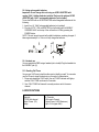
1
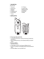
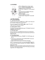
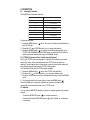
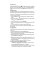
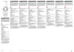
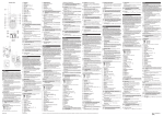
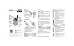
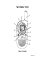
User Guide
U8003010/3
1. DESCRIPTION
(see front cover)
1.
2.
3.
4.
5.
6.
7.
Microphone
Monitor button
Talk button
Call button
Transmission LED
Ear/mic/charger
Antenna
8. LCD display
9. Up/Down button
10.Menu/Lock button
11. On/Off button
12.Scan button
13.Speaker
2. INSTALLATION
1
2
3
4
2.1. Removing/Installing the Belt Clip
1. To remove the clip from the unit, push up on the belt clip (2) while pulling
the clip tab (1).
2. When re-installing the belt clip, a click indicates the BeltClip is locked into
position.
2.2. Battery Installation
1. Remove the belt clip (2).
2. Pull the Battery Cover Tab (4) and remove the Battery Cover (3).
3. Install four ‘AAA’ alkaline or rechargeable batteries following the polarity as
shown.
4. Re-install the Battery Cover (3) and Belt Clip (2).
3. LCD SCREEN
A
B
C
D
I
VX SC
H
G F
E
a. RX icon. Displayed when receiving a signal.
b. TX icon. Displayed when transmitting a signal.
c. Displays the current VOLUME LEVEL.
d. CTCSS code. Changes from 1 to 38 as selected
by user.
e. Displayed during the CHANNEL SCAN mode.
f. Displays during the VOX mode.
g. Button lock symbol
h. The current battery level charge.
i. Channel number. Changes from 1-8 as selected
by user.
4. GETTING STARTED
4.1. Turning the Unit ON/OFF
To activate; press and hold the POWER button ( ) . The unit will “beep” and
the LCD Screen will display the current channel.
To switch off; press and hold the POWER ( ) button again. The unit will
“beep” and the LCD Screen will turn blank.
4.2. Adjusting Speaker Volume.
The Speaker Volume can be adjusted using
/ . The Speaker Volume level
is displayed on the LCD(see §3)
4.3. Receiving a Signal
The unit is continuously in the RECEIVE mode when the unit is ON and not
transmitting. When you receive a signal on the current channel, the RX icon is
displayed (see §3)
4.4. Transmitting a Signal
1. Press and hold the TALK button to TRANSMIT. The TX LED indicator will
light up
2. Hold the unit in a vertical position with the MICROPHONE 5 cm from the
mouth and speak into the microphone.
3. Release the TALK button when you have finished transmitting.
NOTE: To check the channel activity; press and hold the MONITOR
button.
You’ll hear static if the channel is unoccupied. Don’t TRANSMIT if someone is
talking on the channel.
IMPORTANT: In order for other people to receive your transmission, they must
also be on the same channel and have set the CTCSS code you are currently
using. Refer to the ‘Changing Channels’
5. OPERATION
5.1. Changing Channels
The PMRS has 8 available channels.
CHAN. No.
FREQ. (MHz)
446.00625
446.01875
446.03125
446.04375
446.05625
446.06875
446.08125
446.09375
1
2
3
4
5
6
7
8
To change channels:
1. Press the MENU button ( ) once, the current channel number flashes on
the LCD Screen.
2. Press the UP ( ) or DOWN button ( ) to change the channel.
3. Press the MENU button ( ) to confirm the channel selection and go to
CTCSS SUB-CHANNEL SELECTION mode, or press the TALK button to
select the desired channel and return to NORMAL mode.
5.2. CTCSS (Continuous Tone Coded Squelch System)
The 2 digit CTCSS code corresponds to a specific tone frequency the radio
emits. Two users, with the same channel and CTCSS set can hear one
another.They will not be able to hear anyone else on the channel unless the
other radios have the same exact CTCSS code enabled.
The Twintalker 3000 has 38 CTCSS codes available.
1. Press the MENU button ( ) twice, the CTCSS code will flash
2. Press the UP ( ) or DOWN button ( ) to move to another code.
3. Press the TALK button to confirm your selection and return to the NORMAL
mode.
4. To confirm and shift to the next option, press the MENU button
.
Note: Any PMR set on the same channel can receive and listen to the
conversation, also when the other use a CTCSS code.
5.3. Monitor
You can use the MONITOR feature to check for weaker signals in the current
channel.
• Press the MONITOR button (
) for normal monitoring.
• Press and hold the MONITOR button (
monitoring.
) until it “beeps” for continuous
5.4. Button Lock
Press and hold the MENU button ( ) for 5 seconds to activate or deactivate
the BUTTON LOCK mode. The BUTTON LOCK icon is displayed on the LCD
Screen.Press and hold the MENU button ( ) again to deactivate BUTTON
LOCK
5.5. VOX Selection
The PMRS is capable of voice activated (VOX) transmission. In VOX mode,
the radio will transmit a signal when it is activated by your voice or other sound
around you. VOX operation is not recommended If you plan to use your radio
in a noisy or windy environment.
1. Press the MENU button ( ) 3 times, the VX icon will blink on the LCD
Screen.
2. Press the UP button ( ) to turn the VOX feature ON, or press the DOWN
button ( ) to turn the VOX feature OFF.
3. In the VOX mode, the VX icon will be displayed.
4. To confirm your selection and return to the NORMAL mode, press the TALK
button.
5. To confirm and shift to the next option, press the MENU button.
NOTE: To save power, the unit will not turn ON the LCD Screen light when in
the VOX mode.
5.6. Channel Scan
CHANNEL SCAN performs searches for active signals in an endless loop from
channel 1 to 8.
1. Press the SCAN S button to activate CHANNEL SCAN.
2. When an active signal (one of 8 channels) is detected, CHANNEL SCAN
pauses and you will hear the active signal.
3. Press the TALK button to communicate through the active signal channel
and CHANNEL SCAN is deactivated.
4. When an active signal (one of 8 channels) is detected, press the UP ( ) or
DOWN button ( ) to bypass the current channel and continue to search for
another active channel
5. Press the SCAN button to deactivate CHANNEL SCAN mode.
5.7. Battery Charge Level/Low Battery Indication
• The BATTERY CHARGE LEVEL is indicated by the number of squares
present inside the BATTERY icon on the LCD Screen.
• When the BATTERY CHARGE LEVEL is low, the BATTERY icon will flash
to indicate that the batteries need to be replaced or recharged.
5.8. Using rechargeable batteries.
Important: Do not charge this unit using an AC/DC ADAPTER with
regular “AAA” alkaline batteries installed. Only use the optional AC/DC
ADAPTER with “AAA” rechargeable batteries (not included).
To use the PMR with an AC/DC ADAPTER and rechargeable batteries do the
following:
1. Insert four (4) “AAA” rechargeable batteries (not included).
2. Plug the 6 V DC / 300 mA ADAPTER (not included) into the EAR/MIC/
CHARGER JACK on the top of the unit and turn it ON by pressing the
POWER button.
NOTE: The unit cannot transmit calls while the batteries are being charged. It
takes approximately 8 to 10 hours to fully charge the batteries.
Sp
Mic
5.9. .Headset use
You can operate the PMR using a headset (not included).Plug the headset into
the EAR/MIC jack (6).
5.10. Sending Call Tones
You can use Call Tones to alert the other user to identify yourself. You can also
use Call Tones to signal the beginning or the end of a transmission.
1. Press and release the CALL button, the red TX LED indicator will lightup
and the CALL TONE continues for 3 seconds.
2. Your CALL TONES will transmit to nearby receivers set to the same
channel.
6. SPECIFICATIONS
Channels
CTCSS Sub-channel
Output Power (TX)
Range
8 Channels
38 for each Channel
Output Power :0.5W (Maximum)
Up to 3 Km (open field)
7. SAFETY INSTRUCTIONS
7.1. Damage antenna.
Do not use any communicator that has a damaged Antenna. If a damaged
antenna comes in contact with the skin, a minor burn may result.
7.2. Batteries.
As batteries can cause property damage and/or bodily injury such as burns if
conductive material such as jewelry, keys or beaded chains touches exposed
terminals. The material may complete an electrical circuit (short circuit) and
become quite hot. Exercise care in handling any charged battery, particularly
when placing it inside a pocket, purse or other container with metal objects.Do
not replace or charge batteries in a potentially explosive atmosphere. Contact
sparking may occur while installing or removing batteries and cause an
explosion.
7.3. For vehicles with air bag.
Do not place your Communicator in the area over an air bag or in the air bad
deployment area. Air bags inflate with great force. If a communicator is placed
in the bag deployment area and the air bag inflates, the communicator may be
propelled with great force and cause serious injury to the occupants of vehicle.
7.4. Potentially Explosive Atmospheres.
Turn your communicator off when in any area with a potentially explosive
atmosphere, unless it is a type specifically qualified for such use. Sparks in
such areas could cause an explosion or fire resulting in bodily injury or even
death.
7.5. Blasting caps and areas
To avoid possible interference with blasting operation, turn your communicator
off near electrical blasting caps or in a ‘blasting area’ or in areas posted : ‘Turn
off two way radio’. Obey all signs and instructions.
Note : Areas with potentially explosive atmospheres are often, but not always,
clearly marked. They include fueling areas such as below deck on boats, fuel
or chemical transfer or storage facilities; areas where the air contains
chemicals or particles, such as grain, dust or metal powders; and any other
area where you would normally be advised to turn off your vehicle engine.
7.6. Electromagnetic Interference/Compatibility:
Nearly every electronic device is susceptible to electromagnetic interference
(EMI) if inadequately shielded, designed or otherwise configured for
electromagnetic compatibility.
Turn your unit OFF in any facilities where posted notices instruct you to do so.
Hospitals or health care facilities may be using equipment that is sensitive to
external RF energy.
Turn your unit OFF when on board an aircraft when instructed to do so. Any
use of the unit must be accordance with airline regulations or crew
instructions.
8. CARE AND MAINTENANCE
To clean the unit, wipe with a soft cloth dampened with water. Don’t use a
cleaner or solvents on the unit; they can harm the case and leak inside,
causing permanent damage. Battery contacts may be wiped with a dry lint-free
cloth. If the unit gets wet, turn it off and remove the batteries immediately. Dry
the BATTERY COMPARTMENT with a solf cloth to minimize potential water
damage. Leave the cover off the BATTERY COMPARTMENT overnight or
until completely dry. Do not use the unit until completely dry.
9. WARRANTY
This equipment comes with a 24-month warranty. The warranty will be
honoured on presentation of the original or a copy bill or receipt, provided the
date of purchase and the unit type are indicated.
During the time of the warranty Topcom will repair free of charge any defects
caused by material or manufacturing faults. Topcom will at its own discretion
fulfil its warranty obligations by either repairing or exchanging the faulty
equipment.
Any warranty claims will be invalidated as a result of intervention by the buyer
or unqualified third parties.
Damage caused by inexpert treatment or operation, and damage resulting
from the use of non-original parts or accessories not recommended by
Topcom is not covered by the warranty.
The warranty does not cover damage caused by outside factors, such as
lightning, water and fire, nor does it apply if the unit numbers on the equipment
have been changed, removed or rendered illegible.
Note: Please do not forget to enclose your receipt if you return the equipment.